Embed Size (px)
Citation preview

Redundáns multi-manipulátor rendszerek irányítása
Control of Redundant Multi-Manipulator Systems
Diplomaterv - Diploma Thesis
Budapesti Műszaki és Gazdaságtudományi Egyetem – Irányítástechnika és Informatika Tanszék
Budapest University of Technology and Economics –
Department of Control Engineering and Information Technology
Haidegger Tamás
Villamosmérnöki szak - Faculty of Electrical Engineering [email protected]
Konzulensek - Supervisors:
Kemény Zsolt PhD MTA SZTAKI Intelligens Gyártás Munkacsoport Harmati István PhD BME Irányítástechnika és Informatika Tanszék
Budapest, 17. 05. 2006

Control of Redundant Multi-manipulator Systems
- 2 -
Diplomaterv feladat
Haidegger Tamás Szigorló villamosmérnök hallgató részére
Redundáns multi-manipulátor rendszerek irányítása
A korszerű ipari alkalmazásokban a komplex robotikai feladatok elvégzése egyre gyakrabban
multi-manipulátor rendszerek irányításával történik. Ilyen esetekben a robotkarok kooperatív
munkavégzése és a redundáns szabadságfokokkal rendelkező robotok alkalmazása lehetővé teszi
bonyolult tárgymanipulációs feladatok végrehajtását. A redundáns robotok irányítása (pl. orvosi
robotikában, űrkutatásban) azonban az extra szabadságfokok miatt a robotirányítás egy nagy
kihívást jelentő feladata, amelyet több, az utóbbi időben megjelent tudományos munka is
alátámaszt.
Elvégzendő feladatok:
1. Tervezzen multi-manipulátor rendszert elrendezést, amely képes akadályt tartalmazó térben
egyszerűbb tárgymanipulációs feladatok sikeres végrehajtására. Vizsgáljon meg több
redundáns robotok kinematikai irányítására szolgáló algoritmust (pszeudo-inverse, Full
Space Parameterization - FSP, Parameterization Through Null Space – PNS, stb.).
Hasonlítsa össze az FSP és PNS módszert egy tipikus robotmanipulációs példán keresztül.
2. Tervezzen és implementáljon MATLAB környezetben redundáns robotok inverz
kinematikáján alapuló differenciális mozgástervezést magtéren keresztül végrehajtott
parametrizációval (PNS). A rendszer legyen képes a szimulációs eredmények
megjelenítésére a RobMotion vizualizációs környezetben.
3. A már implementált algoritmus továbbfejlesztésével adjon meg multi-manipulátor
mozgástervezésére alkalmas módszert. A szimulációs eredményeket jelenítse meg a
RobMotion környezetben.
Külső konzulens: Kemény Zsolt PhD, tudományos főmunkatárs
MTA-SZTAKI Intelligens Gyártás Munkacsoport
Tanszéki konzulens: Harmati István PhD, adjunktus
BME Irányítástechnika és Informatika Tanszék
Beadási határidő: 2006. május 19.
Záróvizsga tárgyak: 1. Robotok irányítása BMEVIFO 4213
2. A robotirányítás rendszertechnikája BMEVIAU 4010
3. Háromdimenzios látórendszer BMEVIFO 5261
Budapest, 2006. április 13.
Dr. Arató Péter
egyetemi tanár
tanszékvezető
P.H.

Control of Redundant Multi-manipulator Systems
- 3 -
Description of Diploma Project
Tamás Haidegger Candidate for M.Sc. in Electrical Engineering
Control of Redundant Multi-Manipulator Systems
In present days’ industrial applications multi-manipulator systems are used more often to
solve complex tasks. Cooperative robotic arms are controlled together, and because of the
redundancy regarding the kinematic degrees of freedom, these systems are capable of performing
complicated object manipulation tasks. Due to the high costs, these systems have been
implemented in special fields of application with extreme requirements. One can meet them in
space and in computer integrated surgery. The first generation of surgical robots was developed
from industrial manipulators. In case of human operations only teleoperated robots are used for
safety reasons. Autonomous and precise robots will form the next generation of multi-
manipulators. The control of these systems holds great challenge due to the extra degrees of
freedom; numerous recent publications dealt with the problem.
Tasks to be solved:
4. Create the plans of a multi-manipulator system that can overcome the difficulties caused by
obstacles within its workspace. Examine several motion planning algorithm for redundant
manipulator (pseudo-inverse, Full Space Parameterization - FSP, Parameterization Through
Null Space – PNS, etc.) Measure and test the FSP and PNS methods against each other
through the example of a typical manipulation task.
5. Design and implement an inverse kinematics based differential motion planning algorithm in
MATLAB environment, using the Parameterizations Through Null Space - PNS method.
The results gained from the control system should be presented in the RobMotion visual
environment.
6. Based on the previously implemented control method, develop and implement a complex
algorithm for multi-manipulator motion planning. The results should be visualized with the
help of the RobMotion.
Supervisors: Zsolt KEMENY PhD, Senior research associate
(MTA - SZTAKI Intelligent Manufacturing Research Group)
Istvan HARMATI PhD, Assistant Professor,
(BME Dept. of Control Engineering and Information Technology)
Deadline: May 19, 2006
Final exams: 1. Robotok irányítása BMEVIFO 4213
2. A robotirányítás rendszertechnikája BMEVIAU 4010
3. Háromdimenzios látórendszerek BMEVIFO 5261
Budapest, April 14, 2006
Dr. Sc. Péter Arató
Head of Department
P.H.

Control of Redundant Multi-manipulator Systems
- 4 -
Nyilatkozat
Alulírott Haidegger Tamás, a Budapesti Műszaki és Gazdaságtudományi Egyetem
hallgatója kijelentem, hogy ezt a diplomatervet meg nem engedett segítség nélkül, saját
magam készítettem, és a diplomatervben csak a megadott forrásokat használtam fel.
Minden olyan részt, melyet szó szerint, vagy azonos értelemben, de átfogalmazva más
forrásból átvettem, egyértelműen a forrás megadásával megjelöltem.
Declaration
I, undersigned, Tamás Haidegger, student at the Budapest University of Technology
and Economics hereby state that this Diploma is my own work wherein I have only used
the sources listed in the Bibliography. All parts taken from other works, either in citation
or rewritten keeping the original contents, have been unambiguously marked by a
reference to the source.
…..……….……………
Haidegger Tamás
Budapest, 17.05.2006.

Control of Redundant Multi-manipulator Systems
- 5 -
Kivonat
A redundáns többkarú manipulátor rendszerek a robotika rendkívül
dinamikusan fejlődő ágát képezik. Bonyolult irányíthatóságuk és magas költségük
miatt elsősorban különleges elvárásokat támasztó alkalmazások esetében
találkozhatunk velük. Egy egyszerű, megbízható és a redundanciát univerzálisan
kezelő irányítási algoritmus megalkotásával az ügyesebb és hatékonyabb flexibilis
manipulátorok leválthatnák a mai hat szabadságfokú robotokat.
A kinematikai redundancia kiválóan használható mozgáskorlátozások
leküzdésére, akadálykerülésre, illetve a robot gyorsabbá tételére. Új irányítási
paradigmák segítségével a felmerülő hátrányok leküzdhetők, így ezek a rendszerek
is kikerülhetnek a kísérleti laboratóriumokból, és alkalmazásba állhatnak.
A diplomatervben bemutatásra kerül két olyan speciális felhasználási terület,
ahol a redundáns multi-manipulátorok már bizonyítottak, és használatuk számos
kézzelfogható előnnyel jár. Ezek az űrkutatás és az orvostechnika.
Munkám célja egy új, flexibilis orvosi robot struktúrájának megalkotása mellett
a többkarú redundáns robot rendszer-irányítási algoritmusainak megvalósítása volt.
Számos korábbi kinematika alapú irányítási algoritmus bemutatása és
összehasonlítása révén értékelni tudtam az egyes megoldásokat, és a
legmegfelelőbbnek talált Parameterization Through Null Space (PNS) módszer
implementálásán keresztül konkrét szimulációs eredményekhez jutottam. Korábbi
robotokat mintául véve, elméleti megfontolásokra alapozva dolgoztam ki a
robotstruktúrát, amelynek alacsony szintű irányítását PNS módszerrel valósítottam
meg, magas szinten pedig összetett vezérlést implementáltam. Az így kapott
irányítási rendszer gyors és megbízható megoldáshoz vezetett, amely a tesztek
során alkalmasnak bizonyult a kitűzött vezérlési feladatok elvégzésére, továbbá
kiindulási alapként szolgálhat újabb kutatásokhoz.

Control of Redundant Multi-manipulator Systems
- 6 -
Abstract
Redundant multi-manipulator systems represent an emerging field of robotics.
Nowadays we can primary find them in special applications, because of
complications in their control and high specific costs. Given a universal, reliable and
robust solution for the kinematic control problems, redundant robotic arms could
replace present day’s six degree of freedom manipulators in several installations.
Redundancy can be used to overcome special movement constraints, to avoid
obstacles or to make the robot move much faster. The occurring difficulties can be
overcome by introducing new control paradigms, therefore these robots may leave
the research laboratories and be used in real-life applications.
In this Diploma thesis two special fields of applications are presented, where
redundant multi-manipulators are used; space robotics and surgical robotics. The
advantages of redundancy are highly exploited in these systems.
The aim of my work was to develop and design a new surgical robotic system,
create plans of the physical system and design adequate motion control for the
multi-armed manipulator. By examining and testing several previous solutions for the
control of kinematic redundancy, I have identified the Parameterization Through Null
Space (PNS) method as the most appropriate for low level motion planning. For high
level motion planning a complex algorithm has been implemented. The resulted
robotic architecture and controller—driven by PNS—have been tested in a special
simulation environment, and have been verified for the desired tasks. The new
system can serve as a basis for further researches.

Control of Redundant Multi-manipulator Systems
- 7 -
Acknowledgements
I am grateful to Zsolt Kemény for his cooperation and help. I could greatly
build on his work realizing my Diploma Project. István Harmati has also helped me
with great ideas and advices. Special thanks go to Gergely Petrik for developing
RobMotion and upgrading it according to my wishes.

Control of Redundant Multi-manipulator Systems
- 8 -
Contents
Introduction................................................................................................................. 9 Problem statement................................................................................................ 11 Scope and interest of the work.............................................................................. 11 Methodology ......................................................................................................... 12 Structure of the thesis ........................................................................................... 12 Notations and symbols.......................................................................................... 13
1. History and background........................................................................................ 14 1.1 Ontology.......................................................................................................... 14 1.2 Overview of literature ...................................................................................... 15 1.3 Redundant industrial robots ............................................................................ 16
2. Extreme robotics................................................................................................... 18 2.1 Robotic arms in space..................................................................................... 18 2.2 Medical robotics .............................................................................................. 22
2.2.1 Robotic equipment.................................................................................... 22 2.2.2 Mayor surgical robot systems................................................................... 25 2.2.4 Advantages of surgical robots .................................................................. 28 2.2.5 Trends in research.................................................................................... 31
3. Control of redundant manipulators ....................................................................... 36 3.1 Robot control................................................................................................... 36 3.2 Differential motion planning............................................................................. 43 3.3 Full Space Parameterization ........................................................................... 46 3.4 Parameterization Through Null Space ............................................................ 48 3.5 Comparison of FSP and PNS ......................................................................... 52 3.6 Inverse kinematics .......................................................................................... 54 3.7 Control of multi-manipulators .......................................................................... 55
4. Roboflex system ................................................................................................... 58 4.1 New robotic system......................................................................................... 58 4.2 System parameters ......................................................................................... 59 4.3 Control of Roboflex ......................................................................................... 63 4.4 Simulation environment................................................................................... 66 4.5 Functions of the system .................................................................................. 72 4.6 Numeric results ............................................................................................... 74 4.7 Future work ..................................................................................................... 81
Conclusion................................................................................................................ 83 Appendix................................................................................................................... 86 References ............................................................................................................... 87

Control of Redundant Multi-manipulator Systems
- 9 -
Introduction
Robotics was born as an interdisciplinary field of science, combining
mechanics, electronics and control theory, while artificial intelligence has also joined
recently. This fascinating subject has widened and broadened, and now contains
several subfields, from automatic hoovers to electric knives, harmonized multiple
wheel-drives and control algorithms.
Considering robots, we should differentiate them based on several criteria,
e.g. mobility, structure, functionality. Autonomous robot vehicles are able to move on
two-dimensional surfaces by using wheels, with very limited capabilities in the third
dimension. Walking robots are designed to move through rough terrains using
artificial legs. On the other hand, manipulators–or robotic arms–have a fix base, and
can operate on a limited workspace. Structurally, these are massively distributed,
physically embedded, autonomous systems with a large array of fixed location
sensors and actuators.
One of the earliest branches of robotics is the field of robotic arms, also called
manipulators. These structures consist of links and joints which are traditionally
anchored to a certain place, and cannot relocate themselves. The joints are the
cornerstones of the manipulators, allowing them to take several configurations. Being
either revolute or prismatic, the joints are used to position the robot’s end effector into
a given location and orientation, provided it is within their range of workspace.
Classical robotic arm’s joints are named shoulder, elbow and wrist, each containing a

Control of Redundant Multi-manipulator Systems
- 10 -
servomotor, allowing the structure to move like the human arm, only in larger range.
The motors are equipped with their own brakes, sensors and joint-motor speed
controls.
End effectors are the means of the robots through which they can manipulate
their physical surrounding. There exists a great variety of effectors from grippers to
screwdrivers. In case of most applications, it is an expectation toward end effectors to
be multi-functional, e.g. equipped with changeable tool pallets. The end effectors
may have to function as interfaces to other, more complex tools or smaller robots.
The soul of the whole system is the controller. It is the robot's brain running the
control-algorithms of the movements. It is a kind of computer, used to store
information about the robot, the environment and executing programs operating the
robot. The control system contains not only data algorithms, but also logic analysis
and various other processing activities, enabling the robot to operate the needed
functions. Besides, the hardware should provide enough computational power to the
system, and keep it running. Security and reliability is even more important than
performance. Likely, for another period of time, automatic and manual control will go
hand in hand; computers do all the routine work, but allow humans to intervene. The
higher level of integrated adaptivity will shift the balance toward autonomous systems
in the near future.
Teleoperation is still a commonly used form of human control, meaning that
the operator can gain unlimited access to the mechanism through a remote control
panel or other interface. Advanced systems are under development to enhance the
human-machine interface, to make the communication even more effective. Speech-
recognition based, biological signal processing and virtual reality integrated systems
are already in use.
Although the industry has successfully integrated the robotic arms since the
1970’s, the development has never stopped, and there are still many challenges and
tasks to solve. New materials, new constructions and new controllers are being
invented to help the evolution of robotics. Even today, all the robotic arms used in
factories or research institutes could be made more accurate, more intelligent and
more flexible. Robots have the potential to change our way of thinking through
effecting economy, human health, widening our knowledge on the universe and

Control of Redundant Multi-manipulator Systems
- 11 -
integrating into our life. As the technology develops, new ways are found to use
robots every day. While the emerging ideas bring new hope and possibilities, they
include potential danger and risk too. We have to take the challenge.
Problem statement
The idea behind this Diploma thesis and the prior project’s primary goal was to
build a strong theoretical basis for the field of special robotics. By focusing on
redundant robotic arms in the mirror of their extreme applications, the chance was
given to start new projects and give current knowledge and understanding of the
special requirements and problems of the topic.
The universal optimal control of redundant manipulators is not solved so far.
Several different methods have already been developed, but there is a great need for
better and more sophisticated solutions. By testing and examining numerous
algorithms, the aim was to prove the advantages of one on another.
Combining the application and the control, a physical system concept has to
be constructed to verify the control theory and assumptions. It is important to keep in
focus the future application of a test robot, depending on the fields of use, the entire
structure of a system should be different. Therefore a carefully designed mechatronic
device should be developed.
Scope and interest of the work
The Diploma Project has been focusing on a new redundant multi-manipulator
setup and an appropriate control algorithm that suits the special needs of surgical
robotics.
A wide range of theoretical and practical solutions have already been
developed to overcome the difficulties of the control of redundancy. The aim of this
work was to present the most important multi-manipulator systems, future trends and
a pack of control methods developed.
Firstly, the already existing similar robotic systems have been examined and
analyzed. Collecting ideas and features of present robots makes the project life-like.

Control of Redundant Multi-manipulator Systems
- 12 -
Secondly, several control algorithms have been closely studied to select the most
effective one that could be used well for a future surgical robotic system. Thirdly, I
have designed a new multi-manipulator system–and named it Roboflex, based on
theoretic considerations. Further on, I have implemented a simulation of the robot,
controlled by the method called Parameterization Through Null Space. Effective
visualization has been used along with the simulation to provide visual feedback as
well.
Methodology
Throughout the whole project, the main goal was to find an appropriate control
method that could solve all the problems of the kinematically redundant new robotic
system. Having tested several different approaches, the most suitable—PNS—has
been selected for realization, simulation and verification.
The theoretical calculations to validate the different control algorithms were
followed by simulation tests. The programs that realize the differential kinematics
based control have been developed under MATLAB 6.5. For visualization purposes,
the RobMotion environment was used, developed at the Department of Control
Engineering an Information Technology at BME.
Structure of the thesis
The Diploma thesis consists of four main parts. Following the Introduction, a
historical overview is given in Chapter 1. Closer examination of two special fields of
multi-armed robotic application can be found in Chapter 2, namely the space
manipulators and medical robots. In Chapter 3, the different control algorithms are
introduced, and three methods are compared more deeply; Pseudo-inverse, Full
Space Parameterization and Parameterization Through Null Space. Finally,
Chapter 4 contains the data on the actual work done, the parameters of the new
robot architecture derived, the realization of the control algorithm and the simulation,
ending with the possible future works outlined before drawing the conclusion.

Control of Redundant Multi-manipulator Systems
- 13 -
Notations and symbols
Common abbreviations DOF Degree(s) of Freedom FSP Full Space Parameterization PNS Parameterization Through Null Space SVD Singular Value Decomposition R Revolute joint in robot equation T Prismatic joint in robot equation D-H Denavit-Hartenberg parameters TR “Tower rotate” joint of a Roboflex arm SH “Shoulder” joint of a Roboflex arm UA “Upper arm” joint of a Roboflex arm EL “Elbow” joint of a Roboflex arm LA “Lower arm” joint of a Roboflex arm WT “Wrist tilt” joint of a Roboflex arm WP “Wrist pan” joint of a Roboflex arm Common symbols m Kinematic DOF of a robot n Workspace dimensionality p m - n redundancy dimensionality x n x 1 generalized workspace posture q m x 1 joint variable vector J(q) n x m Jacobian matrix Ti,j Homogenous transformation between i and j frame Sυ, Cυ Sine and Cosine of υ J+ Moore-Penrose pseudo-inverse of J U, Σ, VT Matrices of SVD; A = U Σ VT
σi singular value i, element Σ(i,i) matrix N Null space base matrix
�p
q , �hq Particular and homogenous solutions of PNS
B, zr Weighting matrix and reference vector β Coefficient matrix for constraints in FSP or PNS ep p x 1 vector with only ones gi a solution of a set of linear equations in FSP t Weighting vector in FSP or PNS tunc Weighting vector for unconstrained solution in FSP or PNS tcorr Weighting vector for correction term in FSP or PNS �
i,dq Prescribed velocity for the ith joint

Control of Redundant Multi-manipulator Systems
- 14 -
Chapter 1
1. History and background
1.1 Ontology
The essence of the kinematical redundancy is that the robotic arm has more
than 6 degrees of freedom (DOF) that is required to reach any given point within the
workspace in a desired orientation. Due to the redundant joints, the robot becomes
more dexterous and able to perform complex tasks. Sometimes these structures are
called flexible arms, though it mainly refers to the low rigidity of the links and joints.
In special cases not only one, but two, three, or even more arms are
integrated into one system—forming a multi-manipulator—to make it able to easily
perform certain compound tasks. Each arm can hold different end effectors or
sensors. Surgical and space robotics outstands from the fields of applications, as in
both cases, the aim is to meet or surpass the dexterity of the human hands.
Figure 1.1 Zeus surgical robot in operation
Figure 1.2 Special Purpose Dexterous Manipulator built for on orbit servicing

Control of Redundant Multi-manipulator Systems
- 15 -
The special safety standards applied to these two fields—concerning both
software and hardware—are unique. Further difficulties arise in space, where the
flexibility of the robot’s segments can be modelled primarily with numerous redundant
joints. Engineers have to develop and build highly reliable systems that are trustful
and remain controllable despite their complexity under all circumstances. Both fields
of application are developing quickly, and the results of related researches will soon
lead to a breakthrough in these technologies.
1.2 Overview of literature
Several international publications have already dealt with the control of robotic
arms. Classical mathematical methods are presented by Lantos in [7], and some
other aspects are rendered by Somló et al. [8]. Murray, Li and Sastry approach a bit
differently the topic, following different conventions in [9]. From the wide range of
books the ZODIAC emerges [10] that sequentially goes through the entire topic of the
robot manipulator control. Firstly, Japanese scientists began to deal with redundant
manipulators in the 1980’s; a general overview can be found in Sezgin’s doctoral
thesis [2]. Further possible control schemes are presented in Tian and Collins’
publication [38]. Presently developed and actively studied modern control paradigms
and algorithms are listed in the thesis of Kemény [1]. Moreover, the Parameterization
Through Null Space method, developed for the MobMan robot has also been
published in this thesis.
Concerning space robotics, Ellery’s book [14] has been closely examined, and
the details of the Special Purpose Dexterous Manipulators’ control were taken from
Xie’s thesis [12], where the three-level impedance control system was described. We
can find several papers and materials concerning space research on the National
Aeronautics and Space Administration’s (NASA) and European Space Agency’s
homepages, though these are more illustrative documents.
One of the most complete and detailed surveys on medical robotics is given by
Taylor and Stoianovici [21]. The mainstream achievements of surgical robotics are
summarized by E. Dombre [20]. Rogers and Cao’s paper [24] and Howe and
Matsuoka’s survey [25] collect and introduce the most important on-going
researches. More specific on surgical robotics and procedures is Gaspadi and
Control of Redundant Multi-manipulator Systems
- 16 -
Di Lorenzo’s paper [28]. Kang dealt with the problem of automation in surgical tasks
in his thesis [23]. Throughout Europe several research laboratories are conducting
experiments with medical robots, probably the most important examples are the
Scuola Superiore Sant'Anna in Pisa, Italy, the LRIMM in Montpellier, the CNES in
Strasbourg, France and the Universitat Karlsruhe in Germany.
Conference and professional symposium documentations supported by IEEE
and other professional organizations provide a great pool of materials relevant to
control engineering. One of the most important events is the annual ICRA
(International Conference on Robotics and Automation) on robotics; regarding space
technology, the IAC (International Astronautical Congress) has to be mentioned and
finally the World Congress on Medical Physics and Biomedical Engineering. Beside
these, all subfields have their own annual international conference.
1.3 Redundant industrial robots
In the past decades, robotics conquered the industry, and in case of several
applications they took the leading roll. The primary concern of the manufacturers
since the early 1970's was to find ways to increase productivity and reduce the cost
of manufacturing. The very first commercial manipulator was the Unimate (Universal
Automation), developed by Joseph Engelberger and George Devol. The first piece
was sold to General Motors in 1960 to produce TV picture tubes. Eleven years later
Nissan Corp was among the firsts to solve the automation of an entire assembly line.
Unimation was followed by NOKIA’s PUMA (Programmable Universal Machine for
Assembly) in 1978, developed primarily for GM. Its universality and accessibility
helped the PUMA to conquer Europe very quickly. In the past two decades, swarms
of general purpose or specialized manipulators have been developed and sold by
thousands around the globe.
In the 1980’s, through the means of computer aided design (CAD), computer
aided manufacturing (CAM), computer numerical control (CNC) and computer
integrated manufacturing (CIM), the wide robotization of factories have started.
Computer integrated manufacturing utilizes CAD, CAM, CNC and robots to create
work cells that perform a series of operations from design to assembly. Robots are
well suited for doing heavy, dangerous and repetitive tasks.
Control of Redundant Multi-manipulator Systems
- 17 -
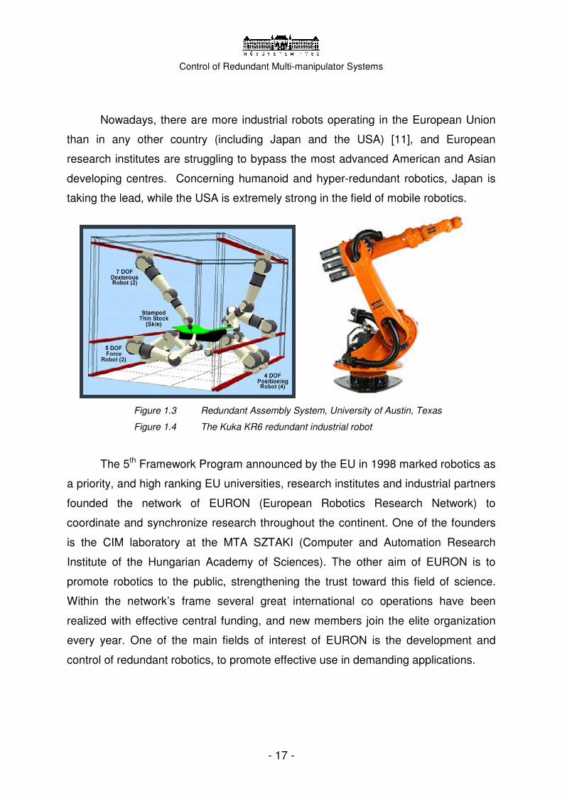
Nowadays, there are more industrial robots operating in the European Union
than in any other country (including Japan and the USA) [11], and European
research institutes are struggling to bypass the most advanced American and Asian
developing centres. Concerning humanoid and hyper-redundant robotics, Japan is
taking the lead, while the USA is extremely strong in the field of mobile robotics.
Figure 1.3 Redundant Assembly System, University of Austin, Texas
Figure 1.4 The Kuka KR6 redundant industrial robot
The 5th Framework Program announced by the EU in 1998 marked robotics as
a priority, and high ranking EU universities, research institutes and industrial partners
founded the network of EURON (European Robotics Research Network) to
coordinate and synchronize research throughout the continent. One of the founders
is the CIM laboratory at the MTA SZTAKI (Computer and Automation Research
Institute of the Hungarian Academy of Sciences). The other aim of EURON is to
promote robotics to the public, strengthening the trust toward this field of science.
Within the network’s frame several great international co operations have been
realized with effective central funding, and new members join the elite organization
every year. One of the main fields of interest of EURON is the development and
control of redundant robotics, to promote effective use in demanding applications.

Control of Redundant Multi-manipulator Systems
- 18 -
Chapter 2
2. Extreme robotics There are two special fields of robotics, where redundant multi-manipulator
systems have already been developed, tested and used; one is space robotics.
Servicing manipulators have been installed on the International Space Station since
2000. The other field of application is medical robotics, and surgical robots in specific,
where complete four-armed systems have been developed and distributed in the past
10 years.
2.1 Robotic arms in space
For quite a long time the vision of space exploration has been keeping the
people exited. However a long debate divides the experts; whether it should be
continued with manned projects or robotic spacecrafts should take the lead. At the
dawn of the space age, robotics was considered the ultimate solution in space
technology: a couple of decades ago scientists expected robots to finally emerge as
individuals replacing humans, opening a safe, automatic and economic era in space
history. Nowadays most scientists would imagine a combined human and robot joint
activation in the future, fully exploiting advantages from both. Soon after military
purpose spending, space technology is one of the most donated fields, where
experimental ideas are realized and tested. Space robotics is a real success story
that had a great effect on the development of robotics back on Earth.
New mobile robots are presently exploring the surface of Mars, special probes
have been sent to the Saturn and the Venus, and the robotic re-exploration of the
Moon is also under discussion. Apart form these special mobile robots, there are
much older systems that has been serving the exploration of deep space for
decades.
The most famous robotic arm used in space is the Canadarm, officially called
Shuttle Remote Manipulator System (SRMS). It was created as a joint venture

Control of Redundant Multi-manipulator Systems
- 19 -
between the governments of the United States of America and of Canada to supply
the Space Shuttle program with a robotic arm. The program began in 1975 and in
April 1981 the first SRMS was delivered to NASA for deployment and retrieval of
space hardware from the payload bay of the orbiter. Realizing the effectiveness and
flexibility of the manipulator, NASA ordered four additional units. The 15-meter-long
arm has performed flawlessly for over 25 years although originally it was designed for
“only” a life of ten years or 100 missions. It helped placing satellites into their proper
orbit and capturing malfunctioning ones for repair. The SRMS itself consists of a
shoulder, elbow and wrist joint separated by an upper and lower arm boom giving it a
total of 6DOF.
Figure 2.1 CANADARM on orbit. The robot has already served several missions
Figure 2.2 CANADARM2 mounted on the International Space Station
The success of the Canadarm inspired specialist to develop a new redundant
arm to serve the International Space Station (ISS). In 2000, the ISS Mobile Servicing
System (MSS) was initiated, to become the primary robotic arm of the station. This
robotic system plays a key role in the space station’s assembly and maintenance:
moving equipment and supplies, supporting astronauts working in space, and
servicing instruments and other payloads attached to the space station. It consists of
three major parts: the central element is Canadarm2, Canadarm’s big brother. It is

Control of Redundant Multi-manipulator Systems
- 20 -
attached to the station via the Mobile Remote Servicer Base System (MSB). Finally,
the MSS’s end effector is a special double-arm itself—Dextre, the Special Purpose
Dexterous Manipulator.
Canadarm2 (Space Station Remote Manipulator System) was launched on
Space Shuttle Endeavour STS-100 in April 2001. It is a bigger, better, smarter
version of the SRMS. Having seven motorized joints (7DOF), it can fully extend to
17.6 metres. In June 2002, the second part of the system was installed. The Mobile
Remote Servicer Base System (MSB) is a work platform that moves along rails
covering the length of the space station, providing lateral mobility for the Canadarm2.
Figure 2.3 Structure of the ISS’ Mobile Servicing System
Figure 2.4 Dextre, a redundant multi-armed robot in space
The final element of the system will be the Special Purpose Dexterous
Manipulator (Dextre). The Canada Hand is scheduled to launch in 2007. With the
help of its two small arms, it will be capable of handling precision tasks previously
only performed by astronauts during space walks; including usage of tools, assembly
missions, installation of equipments and transportation. Dextre will also be equipped
with tactile sensors, lights, video cameras, tool platform and four tool holders. It can
either serve as an end effector of the Canadarm2 (in a micro-macro manipulator
arrangement) or can work parallel with it, attached to the MSB.
Four cameras will allow the ISS crew to observe and control Dextre remotely,
either supporting a space walk team, or working independently. It both increases the
crew’s safety and freeing more time for astronauts for scientific experiments. Just like

Control of Redundant Multi-manipulator Systems
- 21 -
in case of the Canadarm, Dextre was designed similarly to the human body, having a
breast and shoulders that can turn, supporting the arms. The 3.5-meter-long arms
have 7DOF and able to handle masses of up to 600 kg in weightlessness. They can
grip objects with their retractable jaws, and use the Tool Change Mechanism as end
effector. Only one arm can move at a time, partly to avoid bumping into each other—
simplifying the control algorithms—, and giving more stability to the system, by being
fastened onto the station by the unused arm. (The further discussion of its control
algorithm can be found in Chapter 3.)
Development of other robotic arms is also in progress. The European Robotic
Arm (ERA) will be an 11.3-meter-long, relocatable, symmetrical robotic arm with
7DOF. Built by the European Space Agency, ERA is planned to be attached to the
Russian Science and Power Platform in 2007. It will help the installation, deployment
and replacement of the Russian segment of the ISS, support EVAs, transfer ORUs
and perform other assembly tasks, with a maximum payload capacity of 8000 kg in
weightlessness. The arm consists of two end effectors, two booms, seven joints,
together with electronics and cameras. Both ends can act as either an end effector
for the robot or the base from which it can operate.
Figure 2.5 The European Robotic Arm system schematic overview [17]
Figure 2.6 The ERA set up for thermal tests in ESTEC

Control of Redundant Multi-manipulator Systems
- 22 -
The physical requirements towards space manipulators are analogous with the
ones on the Earth, but much stricter. On the other hand, space manipulators have
several features uncommon to ground-based robots; they are highly flexible, often
mobile and usually have a degree of redundancy. In space exploration additional
mobility and redundancy turned to be highly advantageous, allowing to accomplish
complex movements. Special test environments had to be built in order to verify
these systems on Earth before shipping. Even though these flexible robots can
manipulate thousands of tons in weightlessness, they cannot even support their own
weight under regular gravity conditions.
Reliability and long life are crucial characteristics in the hostile environment of
space. Each kilogram of mass transported to orbit at the cost of approximately
22,000USD, the arms once lifted have to be operational for a long time. Built-in
redundancy can help to increase reliability.
2.2 Medical robotics
2.2.1 Robotic equipment
Robotic systems are involved in several fields of medicine. A great variety of
mechatronic instruments have been developed from hand-held electric knives to
room-size robotic equipment. Prominently interesting is the subfield of surgical
robotics. Multi-purpose robot manipulators are used all around the world to perform
different surgical tasks. The continuous development of these systems and the
present days’ research results foretell a breakthrough in surgery robotics. The aim of
this chapter is to shortly introduce the various medical robotic modells, and to present
the advantages and drawbacks of the new technologies.
The field of robotic equipment in healthcare can be divided to five main
categories. Firstly, there are servicing robots to support elderly or disabled people, to
improve their quality of life. Secondly, rehabilitation robots are to improve
neuro-motor functions by direct physical rehabilitation. Diagnostic robots are used to
take measures for data acquisition, while robotic prostheses are primarily getting
more common in case of upper limb replacements. Finally, the category of surgical

Control of Redundant Multi-manipulator Systems
- 23 -
robots consists of complete manipulator systems that are able to assist and perform
complex surgical tasks.
Surgical robots are distinguished based on their functionality. We can talk
about semi-automated robots, directly controlled systems and teleoperated ones. A
great number of different robots have been built in all three categories to perform
desired tasks in neurology, orthopaedic, prostate brachy therapy, urology, breast
biopsy, spine and brain surgery and cardio-vascular operations. Laparoscopic
intervenes are the most widespread field of application, when the surgeon controls
the device through the information provided by an image of endoscope. This
technique is called Minimally Invasive Surgery (MIS), and has several advantages.
MIS means, the surgeon can penetrate into the inner spaces of the human body by
only taking 2-3 incisions, each a few centimetres long, and perform operations
through these, while having endoscopic vision system to give feedback. To improve
versatility, robotic systems with two or three arms have been built. Multi-manipulators
consisting of at least two robots are much more capable of solving complex tasks.
Different end effectors can be used on the tip of each arm, depending on the actual
application; scissors, knives, graspers, needles or sensors or even a mixture of them.
The semi-automated robots’ control scheme is similar to the industrial robots’.
The machine is guided based on an offline path planning algorithm planned on CT,
MRI and other pictures of the patient. When the trajectory planning is ready, the
doctors have to match the robot’s coordinates with the patient’s anatomical points, to
connect the physical space and the robot’s working frame. This process is called
registration. Once appropriately registered, the robot can autonomously perform the
desired task, by following exactly the programmed trajectory.
In other cases, the surgeon can control the robot directly, as a special tool. In
this case, the robot is the extension of the doctor’s hand equipped with special
features and effectors. This technique is often used in case of micromanipulation
operations, such as micro-vascular or urology operations and surgery affecting the
eyes or the brain.

Control of Redundant Multi-manipulator Systems
- 24 -
Figure 2.7 Ultrasound Robot developed at the University of British Columbia
Figure 2.8 Aesop laparoscopic hand-held robot in action
The third category is for the teleoperated devices. These complex systems
consist of three parts; one or more slave manipulators, a master controller and a
vision system providing visual feedback to the controller person. Based on the
gathered visual information, the surgeon controls the slave arm by moving the master
controller (sometimes a small arm itself), and closely watches its effect. The control
signs go through an integrated controller, optional tremor filtering and adjustable
scaling—as it can be seen on Figure 2.9. Sometimes, force-sensors are built in to
provide the surgeon with the feeling of touch, as information about the interaction
between the tissue and the robot’s tip.
Figure 2.9 Block scheme of a typical teleoperated surgical robot [22]

Control of Redundant Multi-manipulator Systems
- 25 -
2.2.2 Mayor surgical robot systems
The first generation of surgical robots was based on modified industrial
manipulators. In the late 1980’s a NOKIA Puma 560 was first transformed to be able
to take tissue samples with the help of a clip. The early-bird systems had several
imperfections; the rigid structures reduced the manoeuvrability of the robots, and
limited the axis of the movements. Only classical 2D visual systems were integrated
with no option to control camera movement or focus.
The Zeus surgical system, initiated by Computer Motion in 1991 was a real
breakthrough. This robot made Minimal Invasive Surgery reality, as the two effector
manipulator and the third camera holder arm could be controlled in master-slave
setup. The Zeus had advanced vision system and precision movement control, to be
able to follow even the tiniest movements of the surgeon. Other features, such as
motion scaling and tremor filtering have also been introduced later.
Figure 2.10-2.11 Zeus, the first 3-armed complete teleoperated surgical robot system
The movements of the doctor’s hands and fingers are tracked with the help of
special sensors, closely attached to the human joints and skin. The two 6DOF slave
manipulators perform exactly the same motion that the doctor’s hand. The result can
be followed via visual system, which consists of a CCD camera mounted on a
separate arm and a TV screen in front of the surgeon. The appearance of Zeus made
several complicated intervenes easier from cardio-vascular surgery to neurosurgery.

Control of Redundant Multi-manipulator Systems
- 26 -
In 2001, its manufacturing was stopped due to economics reasons, to give place to
modern, more dextrous systems. Till nowadays, hundreds of Zeus robots are in
service all around the Earth both in hospitals and research laboratories.
Soon after Zeus–in 1992–Intuitive Surgical’s debuting da Vinci surgical robot
became the most advanced device on the market. Da Vinci overtook Zeus both in
features and ergonomic options. The new advanced vision system’s camera became
fully controlled by the surgeon’s, with the help of simple voice command words. The
control panel evolved into a real command centre, equipped with magnified 3D
monitors and ergonomic movement sensors. The movements of three fingers on the
surgeon’s hand are traced in 3D with special Velcro ring sensors. The master device
itself is imitating a scissor or a lance, letting the doctor to perform the well-practiced
movements.
Da Vinci also consists of two 6DOF slave manipulators, but later, an additional
7th decoupled joint–EndoWrist–has been added to imitate the human wrist’s motion
and to enhance the robot’s dexterity. The CCD camera—equipped with dual
endoscope to enable stereo vision—is mounted on a separate 4DOF robot arm. The
built-in tremor filtering system is able to smooth the signals in real time, and scaling
can be adjusted up to 1/5th of the real size. Da Vinci was the first medical robot to
receive the United States’ FDA’s (Food and Drug Administration) approval in 1997,
and since then it has been verified for 7 different procedures. In the past 5 years
40.000 operations have been performed with approximately 600 da Vincis, only in the
US.
Figure 2.12 The da Vinci complete teleoperated surgical robot

Control of Redundant Multi-manipulator Systems
- 27 -
Besides Zeus and da Vinci, several other robotic systems have been
developed, although no other installation has become so widely used and accepted
than these two. The Canadian McDonald Detwiller company presented its surgical
robotic system in 2001, built on the SPDM space manipulator. With the same
technology that was put into Dextre, they could develop a medical robot called
neuroArm, primarily for brain surgery. The robot contains a 3D visualization system
and several monitoring tools. Two 6DOF haptic interfaces have been integrated for
the smooth control of the two arms, similar to the space robot’s control equipment.
Figure 2.13-2.14 Canadian neuroArm robot, developed based on space technology
Another robot, developed for brain surgery is the NeuroMate from the Detroit
State University. The NeuroMate uses image guided autonomous computer control,
and performs the desired motions planned and validated by the surgeon alone,
based on the several medical imaging systems’ data. The system is capable of
adapting to changing circumstances occurring during the operation, and cooperates
actively with the doctors. The possibility to compensate the fine motions of the
unconscious patient makes the previously used robust anchoring frames
unnecessary.
Further researches have been underway throughout the world to develop and
construct more and more effective medical robots. Some are based on entirely

Control of Redundant Multi-manipulator Systems
- 28 -
different schemes, such as the SurgiScope parallel robot (ABB and Humboldt
Universitat), which is based on Clavel idea, and moves rigid segments very quickly to
reach the desired position. This ceiling-mounted robot is equipped with a 20kg
microscope to support the medical procedures.
Figure 2.15 NeuroMate robot, guided by MRI pictures
Figure 2.16 Ceiling-mounted SurgiScope, with medical microscope at the end
2.2.4 Advantages of surgical robots
The integration of surgical robots into regular procedures reduces the average
invasiveness of the operation, evokes less tissue damage and leads to shorter
recovery time, therefore shorter stay in hospital. These advantages greatly help the
spreading of the manipulators; however, the huge initial costs of installation may
prevent less wealthy hospitals and other institutes from buying it. Most of the robots
are in work in North America and Western Europe. Unfortunately, at present moment,
there is no surgical robot in Hungary; although other medical robots have already
appeared. The Hungarian RehaRob project should be noted; an internationally
recognized physiotherapeutic robot, developed by the Budapest University of
Technology and Economics and four other institutes for upper limb motion therapy for
the disabled.

Control of Redundant Multi-manipulator Systems
- 29 -
Figure 2.17 Schematic picture of the RehaRob rehabilitation robot [31]
Figure 2.18 Personalized, three-dimensional motion therapy by RehaRob
The use of surgical robots leads to new operation techniques. Due to the fine
manipulation, microsurgical processes can be performed in sensitive areas, such as
the prostate or the brain, coronary bypass surgery and so on. The robot can easily
follow a path by less then 0.1 millimetre accuracy that only a few master-surgeon
could repeat. The tremor-filtered, smoothened and scaled motion of the robot
enables its usage even in critical procedures. The comparison of the most important
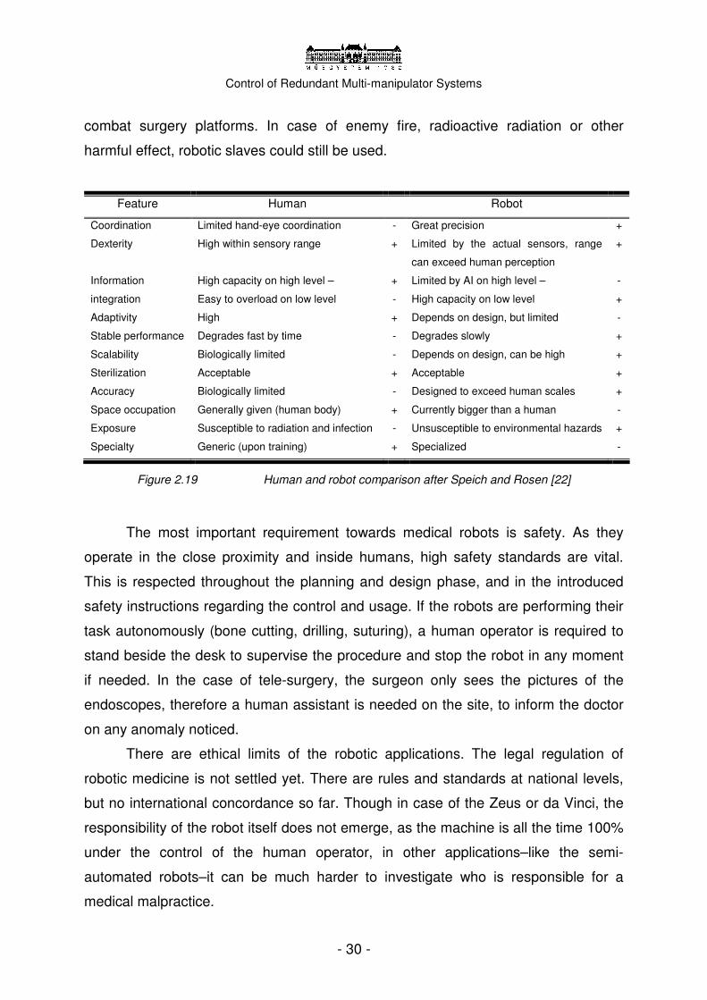
features of human and robotic surgeons can be seen in Figure 2.19.
The other great advantage of surgical robots besides precision is
teleoperation. The human controller does not have to be in physical or visual
proximity of the patient, the master device can be placed within a neighbouring room,
or on another continent. In 2001 successful operation was performed through the
Atlantic; the surgeons in New York guided the robot inside the patient in Strasbourg.
The two sites were connected via high capacity fibre optic wire. Later, within the
frames of a simulation, doctors performed a virtual operation on the International
Space Station, guided from the Earth. The teleoperation technique could be
extremely valuable in situations, where technology is easier to provide than human
professionals. The US Army is seriously interested in the technology for mobile
Control of Redundant Multi-manipulator Systems
- 30 -
combat surgery platforms. In case of enemy fire, radioactive radiation or other
harmful effect, robotic slaves could still be used.
Feature Human Robot
Coordination Limited hand-eye coordination - Great precision +
Dexterity High within sensory range + Limited by the actual sensors, range
can exceed human perception
+
Information
integration
High capacity on high level –
Easy to overload on low level
+
-
Limited by AI on high level –
High capacity on low level
-
+
Adaptivity High + Depends on design, but limited -
Stable performance Degrades fast by time - Degrades slowly +
Scalability Biologically limited - Depends on design, can be high +
Sterilization Acceptable + Acceptable +
Accuracy Biologically limited - Designed to exceed human scales +
Space occupation Generally given (human body) + Currently bigger than a human -
Exposure Susceptible to radiation and infection - Unsusceptible to environmental hazards +
Specialty Generic (upon training) + Specialized -
Figure 2.19 Human and robot comparison after Speich and Rosen [22]
The most important requirement towards medical robots is safety. As they
operate in the close proximity and inside humans, high safety standards are vital.
This is respected throughout the planning and design phase, and in the introduced
safety instructions regarding the control and usage. If the robots are performing their
task autonomously (bone cutting, drilling, suturing), a human operator is required to
stand beside the desk to supervise the procedure and stop the robot in any moment
if needed. In the case of tele-surgery, the surgeon only sees the pictures of the
endoscopes, therefore a human assistant is needed on the site, to inform the doctor
on any anomaly noticed.
There are ethical limits of the robotic applications. The legal regulation of
robotic medicine is not settled yet. There are rules and standards at national levels,
but no international concordance so far. Though in case of the Zeus or da Vinci, the
responsibility of the robot itself does not emerge, as the machine is all the time 100%
under the control of the human operator, in other applications–like the semi-
automated robots–it can be much harder to investigate who is responsible for a
medical malpractice.

Control of Redundant Multi-manipulator Systems
- 31 -
New technologies have to be integrated to education. As soon as during
college studies, medical students should meet and learn about robotic systems to get
more familiar with them. Public should be convinced of the advantages of these
devices, as they do not mean more risk or danger to the patient; on the contrary, they
make operations more accurate and less painful.
Figure 2.20-2.21 The da Vinci is the most commonly used surgical robot in the world
2.2.5 Trends in research
The global spread of MIS will cause drastic improvement in the quality of
patient treatment. The reduced damage, the precise macro-operations and shorter
recovery time make procedures more liveable and less expensive. Research projects
are focusing on developing dexterous, more complex and versatile systems, that are
safer and easier to control at the same time. Great improvement would be the
introduction of redundant and hyper-redundant manipulators. With the help of these
structures, some operations could be performed through natural body apertures,
avoiding the ripping of the skin around the affected organ. New redundant
architectures mean new challenges in the field of control. Even in case of
teleoperation, while it is relatively simple to map the transformations, projecting the
6DOF movements to the 7DOF arms may require optimization to avoid singularities.
The effective use of redundancy for obstacle avoidance and movement constraints
can only be done with the help of great capacity computers. The ultimate goal is to

Control of Redundant Multi-manipulator Systems
- 32 -
realize all these subtasks autonomously and hide the low level motion control from
the surgeon, so it can solely focus on the flawless execution of the procedure.
Doctors often need a third robotic arm, to assist the operations, to cock
tissues, fix organs and support the success of the operation in other ways. The new
generation of da Vinci consists of three manipulators plus the additional arm for the
endoscope. The complexity of a four manipulator system raises new questions
regarding the control algorithms, and an ergonomic human-machine interface has to
be developed as well. As operations can run for several hours, the control of the
robot must be practical and easy to use.
Several researches are aiming to build tiny autonomous robots that can enter
the human body and travel in the lead or in the vessels, being able to replace the
invasive operation by local medication or physical treatment. The prototypes are
already servicing as remote controlled surveillance systems, equipped with small
cameras and other sensors.
Automation will take its role eventually in medical applications as well.
Suturing is one of the most common and most challenging tasks of surgery; it
requires a lot of practice, professionalism and time to perform. It is a repetitive task
that could well be automated in most of the cases. In MIS, it is hard to perform the
suturing with the two robotic arms. New researches are focusing on the problem of
knot forming, knot placement and tension that could all be done with the help of
adequate computer control.
Figure 2.22 Automated knot tying technique [23]

Control of Redundant Multi-manipulator Systems
- 33 -
Beyond adequate low level motion planning, in some special cases, the
appropriate design is the key to the success. A good example is the Scalpp Skin
Harvester robot from the LIRMM laboratory, Montpellier that is able to take high
quality skin samples automatically—after a teaching phase—by repeating the
surgeon’s motion.
Figure 2.23 Scalpp special purpose “skin harvester” robot from Montpellier
Figure 2.24 Very high quality skin sample created by Scalpp
The manual control and visual systems will also develop a lot. The new–
affordable–3D monitors and displays will be integrated within a few years, combined
with complete virtual reality systems (head mounted displays, gloves, body sensors,
etc). High definition binocular visual systems with custom zoom function will give a
crystal-clear view of the patient’s inner body, greatly improving the performance of
the surgeons. Sensory fusion–combining data gained from different sensory systems
(e.g. MRI and CCD camera)–will provide more information to the surgeons, while
accurately matched anatomic atlases will help their navigation around the organs.
With the use of augmented reality systems, real and virtual images can be merged in
real time to make the operation even smoother. (These technologies could also be
used well in case of classical open surgery.) General purpose head-mounted
displays and Augmented Reality vision software solutions are already being offered
in a large variety.

Control of Redundant Multi-manipulator Systems
- 34 -
Beside vision, the sense of touch can also be used to receive information via
haptic interfaces. Haptic devices enable effective communication between human
and machine with the help of vibration and shaking in one direction, and position
sensing on the other. We are able to control the motion of our hand very smoothly,
and register different frequencies of shaking. It is often critical for the surgeon to
“touch” the organ working with. The sense of touch is the most accurate way to give
information about stiffness, hardness and other surface characteristics. Haptic
feedback means, the operator can actually feel the forces awakening at the tip of the
robot’s arm (registered by a force-torque sensor.) Several researches are conducted
to create the ultimate haptic human-machine interface.
By transmitting forces to the surgeon, the master system becomes an active
device, which raises ethical and legal questions. Moreover, it seems to be inevitable
to integrate several other active autonomous subsystems into the future surgical
manipulators. As the mechatronic devices are getting more and more complex, so
does their control, therefore the need for the automation of routine-like procedures is
rising. While the actual high-level motion control of the robot will stay under the direct
control of the doctor, breathing tracking and heart-beat following will also be
integrated as built-in function, beside tremor filtering. Nowadays, the continuous
movement of the body means a high risk factor, and serious strangulation is used in
special cases, otherwise the doctor would not been able to use a teleoperated
manipulator in procedures affecting the heart.
Other supplementary devices may also have a bright future. The consoles,
interfaces, video imaging systems could be sold as separate products, with several
possible fields of use. Simulators could be built for educational purposes, and
medical students would be able to experience and train almost under real life
conditions, without any hazard. Virtual surgery (virtual reality systems with haptic
interfaces) offers an inexpensive and risk-free alternative to present days’ training
exercises. Basic data for simulation could be easily gathered from real robotic
systems.
With these great new options, surgical robotics will eventually conquer several
fields of classical surgery, allowing doctors to perform operation unimaginable before.

Control of Redundant Multi-manipulator Systems
- 35 -
It is beyond dispute that the field of medical robotics–emerged as an
interdisciplinary science connecting mechatronics and medicine–opens new
perspectives. After Japan and the United States, Europe has also recognized the
potential of robotics in therapy and healing, therefore several research laboratories
began to develop their own systems. With the help of these innovative surgical
robots, hundreds of thousands people’s life could be made easier.
Control of Redundant Multi-manipulator Systems
- 36 -
Chapter 3
3. Control of redundant manipulators 3.1 Robot control Several different algorithms have already been invented to control redundant
manipulators. If a robotic arm has more than 6DOF–which is the minimum to reach
any point in any orientation within its workspace–infinite number of configurations can
belong to a certain prescribed position. This may be a serious problem during the
inverse kinematic calculations, as the classical methods for 6DOF robots may not
give an unambiguous solution. In general we can say that in the case of kinematically
redundant manipulators the final solution is chosen from the many using a secondary
optimization criterion.
Kinematically redundant robots can reach a specific point within their
workspace in infinite numerous configurations in general. That means, instead of a
point, we get a solution sub-space in the configuration space, of which every point
represent a different solution. To choose the appropriate one(s) out of these,
subsidiary criteria are taken into consideration, such as power efficiency, average
speed, distance from previous solution, etc. We can look for a solution iteratively–
using e.g. the Lagrange multiplier rule–optimizing based on the robot’s kinematic
equations, though this method requires more computational power.
Vast literature for various robot controls has been evaluated throughout the
last decades. Only the redundant robot control aspects are investigated here.
(Further references can be found within the thesis of Kemény [1]).
From the 1980’s several different mathematical methods have been developed
to solve the emerging problems. One of the first ideas was to use pseudo-inverse
methods to invert the non-quadratic matrices; however, pseudo-inverting alone does
not make use of any advantages of the kinematic redundancy. In 1995 Sezgin
planned a simple position based algorithm based on the kinematic model, which
used the Lagrange multiplier rule to indulge secondary criteria. Achuatzin and Gupt
Control of Redundant Multi-manipulator Systems
- 37 -
proposed the use of manipulation maps, which contained the best configuration
solution for specific points of the workspace, and used iteration in between two
known points. Dahm et al. developed their method for a 7DOF manipulator, which
instead of solving the problem, eliminates it by mathematically merging together two
joints with appropriate attributes, reducing the robot to 6DOF from computational
point of view.
Configuration control can be an effective way to control the motions of a
redundant robot. In this case, the joint variables of the robot are represented
mathematically by a set of configuration variables that is a generalized coordinate
vector correlating to the desired end effector movement. The generalized coordinate
vector consists of the coordinates of the end effector in task space, plus a number of
kinematic functions that involve the additional DOFs. The kinematic functions can be
selected to define an additional task, the avoidance of obstacles or kinematic
optimization to enhance manipulability. The configuration variables can also be used
in an adaptive controller that does not require knowledge of the complex
mathematical model of the dynamics of the robot or the parameters of the object to
be manipulated. In contrast to pseudo-inverse based methods, the configuration
control scheme ensures cyclic motion of the manipulator, however some difficulties
arises upon calculating the transfer function from task space to joint space.
Beyond position based methods, other solutions have also been invented
based on differential kinematics. The essence of the calculations is to originate the
end effector’s velocity to the joint velocities. In such cases the Jacobian matrix is
used. The Jacobian matrix represents the mapping between the end effector’s and
linear and angular velocities of the subsequent joints, described in the differential
kinematic model
��v
x = = J(q)qω
(1.1)
where J stands for the Jacobian matrix of the robot, q refers to the joint-variables’
vector and x contains the coordinates of the desired position and orientation. The
mathematical definition of the Jacobian matrix is partial derivates of the—joint

Control of Redundant Multi-manipulator Systems
- 38 -
variable dependent—transformation matrices connecting the joint space and the
workspace’s coordinates. Written within the m frame
0 1 m-1
m
0 1 m-1
d d ... dJ =
t t ... t (1.2)
The rows of the Jacobian matrix are corresponding to the workspace coordinates,
and the 3x1 d vectors are referring to the linear velocities, while t refers to the angular
velocities.
There are two widely used methods to calculate the Jacobian matrix. On one
hand, it is possible to determine the partial derivates in the Jacobian matrix once the
kinematic model of the robot is known. This is called the analytical Jacobian matrix.
The geometrical Jacobian matrix on the other hand uses a special set of
homogenous transformations. Let us assume an m-DOF manipulator according to
the Denavit-Hartenberg [7] notations, having the transformation matrices between
each segment respectively
0,m 1,m 2,m m_1,mT , T , T , ... T (1.3)
Each transformation can be decomposed to vectors referring to orientation and position
=
i m
l m n pT , 0 0 0 1
(1.4)
mJm (the Jacobian matrix written for the m segment, expressed in the m frame)’s mdi
and mti vectors can be calculated in case of a revolute joint as follows
m m
i,x i x y y x i,x i z
m m
i,y i x y y x i,y i z
m m
i,z i x y y x i,z i z
d = l ×(k × p)= -l p + l p t = l × k = l
d = m×(k × p)= -m p + m p t = m× k = m
d = n×(k × p)= -n p + n p t = n× k = n
(1.5)
And for prismatic joints
m m
i,x i z i,x
m m
i,y i z i,y
m m
i,x i z i,z
d = l × k = l t = 0
d = m× k = m t = 0
d = n× k = n t = 0
(1.6)
From the calculated mdi and mti vectors the Jacobian matrix can be assembled:
m m mm 0 1 m-1
m m m m
0 1 m-1
d d ... dJ :=
t t ... t (1.7)

Control of Redundant Multi-manipulator Systems
- 39 -
In the classical 6DOF case, the inverse of the Jacobian matrix gives the
unambiguous solution, but because of the redundancy, the Jacobian matrix loses its
quadratic characteristics, therefore becomes non-invertible. Though the
non-quadratic J cannot be inverted classically, with the use of pseudo-inverse
methods, the problem is solvable
� �+q = J x (1.8)
where J+ refers to the pseudo-inverse of the Jacobian. The most frequently used
pseudo-inverse is the Moore-Penrose that minimizes the joint velocity vector’s
Euclidean norm. Other solutions using different norms have also been defined,
leading to similar results.
A commonly used technique is the workspace augmentation, adding new
dimensions to the workspace to fit with the number of joints in the robot. This method
was first proposed by Sciaviccio in the end of the 1980’s and its basic idea is to
enlarge, augment the robot’s n dimensional workspace with appropriate linear
combinations, so that the equations of the redundant robot would have to match with
a same m dimensional task space. The augmented workspace dimensions serve as
realizations of constraints.
Liegeois introduced the method of gradient projection, which add a
homogenous term to the particular minimal Euclidean norm that is securing the end
effector’s desired movement, and therefore able to integrate motion preferences into
the algorithm
� � � �+
p h projq = q + q = J x +αN h (1.9)
The homogenous term is gained from certain gradient based subsidiary movement
condition’s projection with an Nproj matrix to the Jacobian matrix’s null space. In (1.9)
h is the projected vector that can be a joint velocity preference, for example.
Dynamic models are less frequently used to control redundant manipulators.
More commonly used is the arsenal of the soft computing techniques. Several
methods have been developed to control manipulators with fuzzy systems and neural
networks. The fuzzy rules or the weight functions of the neural networks can learn an
approximation of the highly nonlinear mapping function between the movement of the

Control of Redundant Multi-manipulator Systems
- 40 -
joints and the robot’s end effector. One prominent idea is to find solutions close to
optimal with soft computing methods, and cope with local extremes, that simple
gradient base methods cannot handle. Ritter and Chen successfully combined
genetic algorithms and Kohonen maps for path planning. One serious drawback of
soft computing is the insufficient accuracy and the high computational power
required. These methods are not yet suitable for real-time applications alone,
however wisely combining them with classical methods could lead to a superior
control algorithm.
Successful layered impedance control scheme was developed by Xie et al. in
1999, to control the redundant space multi-manipulator, Dextre (see Chapter 2.1).
The basis of the method is to model the interactions between the robot and the
environment by impedances, and once modelled appropriately, the complete
dynamic control can be built on it.
The dynamic equation of the a manipulator’s motion is given by
T R T w
R wMq + h = τ - J F = τ - J F�� (1.10) where the inertia matrix, the joint acceleration vector, the centrifugal, the Coriolis and
the gravity terms and the joint torque vector are respectively
1 7 1 1 1
7 2 2 2 2
M O q hM = , q = , h = , =
O M q h
τ τ
τ
����
�� (1.11)
the Jacobian matrices being
1 1
2 2
wR 6x7 R 6
R W Rw6x7 R 6 R
J O R OJ = , J = J
O J O R
(1.12)
where
1
w
RR refers to the orientation of the R1 robotic arm.
Figure 3.1 shows the model of the system. The controller consists of two levels
of impedance control; one at the object level and another between the end effector’s
tracking error and the internal force error.

Control of Redundant Multi-manipulator Systems
- 41 -
Figure 3.1 Two-level impedance controller [12]
An augmented hybrid impedance controller has been created to achieve
robust control. The desired impedance between the object and the environment is
defined through parameters d d d
o o oM ,B ,K
p p
w t w d
o ow t d -1 w w d d w t w d d w d
o o e e o o o o o
o
x - xx = (M ) F - (I - S) F - B ( x - S x ) - K S + S x
-e
�� � � �� (1.13)
where w t
ox�� is the object target acceleration trajectory, w d w d w d
o o ox , x , x� �� refers to the desired
object trajectory. Furthermore, the eo orientation error is
(3,2) (2,3)
( ) (1,3) (3,1) where ( )
(2,1) (1,2)
err err
err err err err
err err
o o
w d w d T
o o o o o o o
o o
R R
e R R R R R R
R R
−
= Λ = − =
−
(1.14)
and w w d
e eF F are the estimated and desired external forces exerted on the environment by the object, w w w w t w
e o o oF G F M x + h= − �� (1.15)
The desired velocity and acceleration derived as
and w d T w t w d T w t T w t
R o R o ox G x x G x G x= = + �� � �� �� � (1.16) Figure 3.2 presents the control scheme of the algorithm; the required joint
torque is calculated as
c p fτ = τ + τ (1.17)
andd T w
p e w Mq = J Fτ = τ�� (1.18)

Control of Redundant Multi-manipulator Systems
- 42 -
Figure 3.2 Scheme of a simplified Hybrid Impedance Controller [12]
The two arms of the robotic system can work both separately or in closed
chain—hand in hand—supporting the workpiece from two sides. The algorithm
handles rigid and non-rigid payloads differently. The augmented hybrid dual-layer
impedance control is the improved version of Raibert and Draig’s hybrid
position-force control. To resolve redundancy, they use a weighted pseudo inverse
method as the following
�� �i i i
w + w w
i R R R iq = J ( x - J q ) (1.19)
where q stands for the joint velocities’ vector, J means the Jacobian matrix and wxR
the Rth robot’s end effector’s desired position and orientation in frame w. Throughout
the differential kinematic calculations, this pseudo-inverse is used, and the parameter
optimization is performed based on the criterion
{ }� � �i i i i
w d w w dR R R i R imin x - R J q - J q (1.20)
Two distinct methods of operation were developed. In case one, the two arms
are operated separately, though sharing the same workspace. The task for each one
is individually described without reference to the other manipulator. In case of the
second method, the arms are cooperating, e.g. jointly holding a payload. The
dual-layer impedance control proved to be a useful method to minimize the error
between the desired and the actual trajectory, based on the forces applied on the
end effector of the robot. The algorithm ensures that the robotic arm cannot collide

Control of Redundant Multi-manipulator Systems
- 43 -
with itself, nor with the other arm, and will not overrun the prescribed joint velocities.
The algorithm managed to switch smoothly between the two operating mode.
General collision detection was implemented in the higher level motion control. The
only drawback of the method is its complexity, requiring a great amount of
computational capacity.
Figure 3.3 Part of the SPDM robot’s controller [12]
Beyond the inverse kinematic calculations, global scale motion planning
should also be realized. The classical potential field or graph based solutions can be
well used for redundant robots, if combined with adequate collision avoidance
routines (see Chapter 3.7).
3.2 Differential motion planning
Given the differential motion, the relation between the end point angular and
linear velocity and the joint velocity can be calculated using the previous notation
��x = J(q)q (1.21)

Control of Redundant Multi-manipulator Systems
- 44 -
If the Jacobian matrix and the end point’s velocity are given, (1.21) can be
solved easily for a 6DOF robot, giving only one unique solution. This is called the
differential kinematic or resolved motion method, and is widely used.
Figure 3.4 presents the control scheme of the method. The desired end
effector coordinates originating from the high level motion planner are transformed
into desired joint variables to reach that position with the help of the differential
method. By applying the new joint variables, the robot will move as prescribed. The
forward kinematics performs the mapping from the joint space to the world space by
multiplying the adequate Ti,m homogenous transformation matrices.
Figure 3.4 Block diagram of the closed-loop resolved motion control [1]
In case of redundant manipulators (1.21) may have several solutions given in
an m’ dimensional space, where m’ means the number of additional DOFs. In such
cases, a pseudo-inverse can be used, to create the inverse of the non-quadratic J
� �+q = J x (1.22)
The pseudo-inverse can be derived from the singular value decomposition—
SVD—of J. The singular value decomposition was originally developed by differential
geometers, who wished to determine whether a real bilinear form could be made
equal to another by independent orthogonal transformations of the two spaces it acts
on. Any m x n matrix J (m >= n) can be written as the product of an m x n column-
orthogonal matrix U, an n x n diagonal matrix with positive or zero elements Σ, and
the transpose of an n x n orthogonal matrix V
TJ = UΣV (1.23)
U and V will become orthogonal, and UTU = VTV = I. SVD generated the
singular values of the J matrix with appropriate resolution. The singular values (the
positive squareroots of the eigenvalues of JTJ matrix) are in the main diagonal of Σ. If
any of the diagonal elements in Σ is zero, J is singular.

Control of Redundant Multi-manipulator Systems
- 45 -
With the help of the SVD it is easy to create the inverse of the J matrix.
Deriving from above, U-1 = UT and V-1 = VT
-1 T -1 T -1 -1 -1 -1 TJ = (UΣV ) = (V ) Σ U =VΣ U (1.24) The inverse of Σ means that all its elements are separately inverted, as it is a
diagonal matrix. If the elements of Σ are very small, the matrix is ill-conditioned, and
that makes the inverse hard to create. Inversion can be interpreted with the same
technique even for non quadratic J matrices as well. In that case, the result is called
a pseudo-inverse of J
+ -1 TJ =VΣ U (1.25)
J+ stands for the Moore-Penrose (or generalized) pseudo-inverse of the
Jacobian matrix. If J is quadratic (as in the case of a general 6DOF robot), the
pseudo-inverse is equivalent with the inverse of J. Using the pseudo-inverse for
differential motion planning is possible even for redundant manipulators, however the
method will only give one existing mathematical solution from the solution space, and
there is no possibility to optimize along different criteria. It is not suitable for handling
singularities—configuration manifolds—where the motion (velocity) reserve of the
manipulator reduces to zero (or near zero) in any direction. That may cause
difficulties in the resolved motion algorithm and in the actual motion of the
manipulator.
The manipulability or motion reserve of a given configuration can be an
important factor providing information on each joint’s distant to its limit. Moreover, it
describes the maximum possible velocity in the given configuration. Yoshikawa
introduced the concept of manipulability ellipsoids, which is a graphical
representation of the quantitative measure. The manipulability (hyper)ellipsoids give
information about the robot’s velocity reserve to each direction, and can be obtained
as
{ }T
velε = x : x = Jq; q q 1≤� � �� � (1.26)
A scalar measure of the manipulability can be defined based on the Jacobian matrix
TmanipM = det(JJ ) (1.27)

Control of Redundant Multi-manipulator Systems
- 46 -
Singularities occur when Mmanip becomes zero or the manipulability ellipsoid
flattens totally to any direction, as at least one singular value of the Jacobian matrix
decreases to zero. Figure 3.5 shows a 2DOF planar manipulator with drawn
manipulability ellipsoid. It can be noticed, that the ellipsoid flattens as the arm
stretches to its limit. The σ1 and σ2 singular values can be tracked on the upper
diagram; even though σ1 remains high at 0.5, σ2 decreases to zero causing the
Jacobian matrix a rank loss.
Figure 3.5 Manipulability and singular values of a 2DOF planar manipulator [1]
Singular configuration should be avoided during robot control, as they mean a
hindrance on the robot’s motion. Maximizing the manipulability measure can be a
good method to keep the arm on a safe path.
The other problem is the low condition number if the matrices. If a matrix is
ill-conditioned, meaning there are several orders in difference between the main axes
elements, creating the inverse can be troublesome because of the numeric problems
arising, therefore special mathematical methods should be used.
3.3 Full Space Parameterization
The Full Space Parameterization (FSP) is a complex solution worked out by
Pin et al. The FSP gains the solution from the closed form optimization of the criterion
function defined on the entire solution space, considering equality type constraints.

Control of Redundant Multi-manipulator Systems
- 47 -
The FSP tries to take advantage of both the gradient projection and workspace
augmentation, using motion preferences and constraints as well.
Figure 3.6 Scheme of the complete configuration control [1]
The algorithm consists of two parts. Firstly it sets a solution space from base
vectors to solve the (1.21) equation, and secondly, it solves an optimization problem
on that constructed space. The solution space is set from (m-n+1) linearly
independent solutions {gi} of the differential kinematic equation
∈ℜ
∑ ∑� �
�
m-n+1 m-n+1m
i i ki=1 k=1
i
ε = q : q(t)= t g ; t =1
Jg = x; i =1...m - n+1
(1.28)
where weighting vector t gives �q as a weighted sum of all gi solutions. The FSP
looks for possible sources of errors and failures in the equations based on their
numeric properties, and then finds (m-n+1) subsystems (referring to certain parts of
the robot) that deliver a complete set of linearly independent gi solutions. The
analysis of (1.21) leads to the reduction of the Jacobian matrix (J*), firstly by
eliminating zero columns, then dependent rows, restricted rows (containing only one
non-zero element) and two special cases. If J* in invertible, the
�* * -1g = J x (1.29)
equation will give a unique solution.
The selection of the solution space vectors {gi} is performed that in recursion
cycles different subspaces are checked accordingly. Having created the base

Control of Redundant Multi-manipulator Systems
- 48 -
vectors, the optimization is reduced to a simple series of algebraic operations, once
the constraints and the criteria are transformed into proper form. The quadratic
criterion is defined as following
�2
r
1Q = Bq - z
2 (1.30)
where B is a full-rank m*m matrix and zr is a reference vector. The constraints can be
formed into one equation
T
pβ t - e = 0 (1.31)
where β is a (m - n +1)* p matrix with the constraints’ coefficients, and t is the
weighting vector from (1.11) and ep column vector contains ones. The solution vector
is formed with weighting matrix B
T TG := g B Bg (1.32) Vector t is obtained through further equations, and once it is calculated, the weighted
sum of the solution space base vectors {gi} can be determined
�q := gt (1.33) Given a close formula solution for optimization, the computational time is reduced so
that the algorithm can even be used for real time applications.
3.4 Parameterization Through Null Space
The Parameterization Through Null Space (PNS) method described in [1] is
similar to FSP, though it fixes some of the defections of the previous method; PNS is
able to handle configuration states very close to singularities in a more robust
manner and much faster. The difference is that PNS takes alternative optimization
space, which means it searches for solutions in a wider space. The problem is
decomposed into a particular ( �pq ) and a homogenous ( �hq ) term, as in case of
gradient projection. The particular term derives from the pseudo-inverse of the
Jacobian matrix, while the homogenous term derives from the linear combination of
the null space elements of the Jacobian matrix. The homogenous term is calculated
through optimization

Control of Redundant Multi-manipulator Systems
- 49 -
� � � �+
p hq = q + q = J x + Nt (1.34)
Vector t is a weighting vector, and N is the vector formed from base vectors of
the Jacobian matrix’s null space—gained through SVD. The inputs of the algorithm
are the Jacobian and the desired end point velocities. Figure 3.7 shows the
mechanism of the PNS.
Figure 3.7 Block diagram of the PNS method [1]
The first step of the PNS algorithm is the construction of the solution space’s
base vectors. These are derived from the SVD decomposition of the Jacobian. SVD
creates the base vectors in orthogonal normal form. The singular values that do not
belong to the null space create the particular term
TJ = UΣV (1.35)
NN := V (1.36)
+ -1 T
P PJ :=V Σ U (1.37)
U and V derived from the SVD are in orthogonal normal form, and Σ contains
the singular values. Vn contains the null space elements of V. The discrepancy to
FSP is that the pseudo-inverse is calculated only from the non null space elements of
V and Σ. The final solution is composed from the particular term and the linear
combination of the null space elements
� ��+
pq = J x + Nt = q + Nt (1.38)
Throughout the optimization process PNS uses similar criteria and constraint
model as FSP. Though, optimization is only performed with the null space elements.
The idea to separate the homogenous and particular term derives back to the
gradient projection method. Zero velocity commands do not cause any mathematical
problem to the PNS method, as in case of FSP. After having the particular term

Control of Redundant Multi-manipulator Systems
- 50 -
calculated, the PNS method deals with the homogenous one. The criterion Q refers
to the entire solution, with linear equality type constraints
� �2 2
r P r
1 1Q = Bq - z = B(q + Nt) - z
2 2 (1.39)
It is possible to calculate the optimum in closed form. The weighting term t can be
further decomposed, as it represents the optimization criteria. It is composed of an
unconstrained part and a correction term
� �p unc corrq = q + N(t + t ) (1.40)
The unconstrained solution is derived from the null space elements of the V vector
gained from SVD, and a weighting matrix B, considering the motion preferences
(criteria) represented by zr
T TG := N B BN (1.41) �T T T T
p rH := N B Bq - N B z (1.42)
-1
unct := -G H (1.43)
The motion constraints are expressed as follows T -1 T
p p uncd := e + β G H = e + β t (1.44)
T -1A := β G H (1.45)
ν-1:= -A d (1.46)
-1
corrt := -G βν (1.47)
Therefore the final solution can be calculated according to (1.40).
If the robot moves through or near singularities, the calculation of the inverse
can be uneasy, therefore the method has a built-in protection. The Σ matrix’s–derived
from the Jacobian-null space elements are zero, therefore there is no need to invert
those, but more attention should be paid on the non null space elements. In case one
non null space element σi of the matrix Σ goes under a certain threshold, 2*σlim and
closes to zero, the algorithm increases its value and rescale according to a square
function
≥
i
i i lim
2i i
lim i lim
lim
σ if σ 2σ
s (σ ) := σ+σ if σ < 2σ
4σ
(1.48)
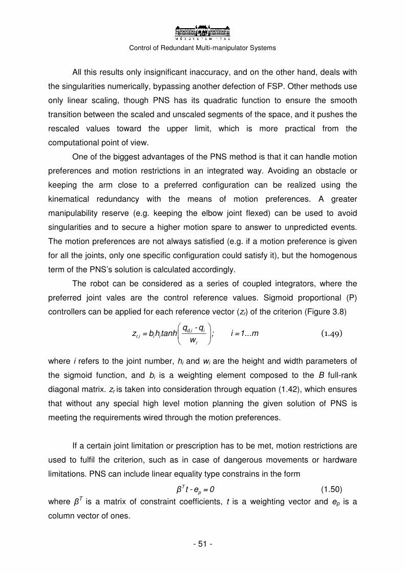
Control of Redundant Multi-manipulator Systems
- 51 -
All this results only insignificant inaccuracy, and on the other hand, deals with
the singularities numerically, bypassing another defection of FSP. Other methods use
only linear scaling, though PNS has its quadratic function to ensure the smooth
transition between the scaled and unscaled segments of the space, and it pushes the
rescaled values toward the upper limit, which is more practical from the
computational point of view.
One of the biggest advantages of the PNS method is that it can handle motion
preferences and motion restrictions in an integrated way. Avoiding an obstacle or
keeping the arm close to a preferred configuration can be realized using the
kinematical redundancy with the means of motion preferences. A greater
manipulability reserve (e.g. keeping the elbow joint flexed) can be used to avoid
singularities and to secure a higher motion spare to answer to unpredicted events.
The motion preferences are not always satisfied (e.g. if a motion preference is given
for all the joints, only one specific configuration could satisfy it), but the homogenous
term of the PNS’s solution is calculated accordingly.
The robot can be considered as a series of coupled integrators, where the
preferred joint vales are the control reference values. Sigmoid proportional (P)
controllers can be applied for each reference vector (zr) of the criterion (Figure 3.8)
d,i i
r,i i i
i
q - qz = b h tanh ; i =1...m
w (1.49)
where i refers to the joint number, hi and wi are the height and width parameters of
the sigmoid function, and bi is a weighting element composed to the B full-rank
diagonal matrix. zr is taken into consideration through equation (1.42), which ensures
that without any special high level motion planning the given solution of PNS is
meeting the requirements wired through the motion preferences.
If a certain joint limitation or prescription has to be met, motion restrictions are
used to fulfil the criterion, such as in case of dangerous movements or hardware
limitations. PNS can include linear equality type constrains in the form
T
pβ t - e = 0 (1.50)
where βT is a matrix of constraint coefficients, t is a weighting vector and ep is a
column vector of ones.
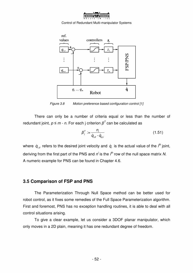
Control of Redundant Multi-manipulator Systems
- 52 -
Figure 3.8 Motion preference based configuration control [1]
There can only be a number of criteria equal or less than the number of
redundant joint, p ≤ m - n. For each j criterion βT can be calculated as
� �
T ij
i,d p,i
nβ :=
q - q (1.51)
where �i dq , refers to the desired joint velocity and �iq is the actual value of the ith joint,
deriving from the first part of the PNS and ni is the ith row of the null space matrix N.
A numeric example for PNS can be found in Chapter 4.6.
3.5 Comparison of FSP and PNS
The Parameterization Through Null Space method can be better used for
robot control, as it fixes some remedies of the Full Space Parameterization algorithm.
First and foremost, PNS has no exception handling routines, it is able to deal with all
control situations arising.
To give a clear example, let us consider a 3DOF planar manipulator, which
only moves in a 2D plain, meaning it has one redundant degree of freedom.
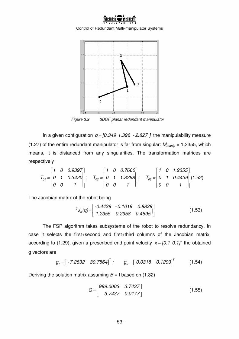
Control of Redundant Multi-manipulator Systems
- 53 -
Figure 3.9 3DOF planar redundant manipulator
In a given configuration q = [0.349 1.396 - 2.827 ] the manipulability measure
(1.27) of the entire redundant manipulator is far from singular: Mmanip = 1.3355, which
means, it is distanced from any singularities. The transformation matrices are
respectively
01 02 03
1 0 0.9397 1 0 0.7660 1 0 1.2355
T = 0 1 0.3420 ; T = 0 1 1.3268 ; T = 0 1 0.4439
0 0 1 0 0 1 0 0 1
(1.52)
The Jacobian matrix of the robot being
3
3
-0.4439 - 0.1019 0.8829J (q)=
1.2355 0.2958 0.4695 (1.53)
The FSP algorithm takes subsystems of the robot to resolve redundancy. In
case it selects the first+second and first+third columns of the Jacobian matrix,
according to (1.29), given a prescribed end-point velocity x = [0.1 0.1]' the obtained
g vectors are
[ ] [ ]T T
1 2g = -7.2832 30.7564 ; g = 0.0318 0.1293 (1.54)
Deriving the solution matrix assuming B = I based on (1.32)
999.0003 3.7437G =
3.7437 0.0177 (1.55)

Control of Redundant Multi-manipulator Systems
- 54 -
The resulted solution matrix is badly scaled, because of the first chosen
subsystem, and can easily cause numeric failures upon inversion. Similar problems
may occur in case of a 3D 6+DOF manipulator, therefore special routines have to be
integrated to the algorithm to monitor and avoid near singular cases.
The other defect of FSP is the handling of zero velocity commands.
Redundant manipulators are able to keep their end effector at the same point in the
same orientation while moving some of the joints. In the case of zero end velocity
command, the selected base vectors are zero vectors, making the optimization
impossible. The problem can be overcome by using the null space of the Jacobian
matrix with fictitious non-zero velocity commands and constraints (instead of the
solution space), however this patch causes the discontinuity of the joint velocity
commands, i.e. it should be avoided in real applications.
Because of the two actual drawbacks of the FSP algorithm and the
complicated structure (with branches and special case handlings), PNS—that is able
to overcome mathematically these difficulties—is preferred for application. The PNS
gives better overview of the intermediate results—the possibility to analyze them, and
is easier to enhance.
3.6 Inverse kinematics
The inverse kinematical problem means, that the appropriate joint vector has
to be determined for a given end point position and orientation. The inverse
transformation between the joint space and the workspace coordinates (T0,m -> q) is
an unambiguous mapping in case of a 6DOF manipulator. If the last three joints are
revolute and their axes are having a common intersection point, the problem can
even be decomposed to a 3DOF position and a 3DOF orientation calculation. Other
mathematical techniques have also been developed to give general solution forms
for typical 6DOF manipulators.
However, in the case of redundant robots, the mapping will no longer remain
unambiguous, therefore further assumptions have to be made to derive the actual
joint vectors for each given position.

Control of Redundant Multi-manipulator Systems
- 55 -
Figure 3.10 Substituting two subsequent joints with a 2DOF spherical joint [1].
Dahm and Joublin developed a method for the inverse kinematic calculation of
redundant manipulators in 1997. In case of appropriate mechanical structure, a
closed format solution can be used. Two subsequent rotational joints can be
modelled with one 2DOF spherical joint, if their axes fall into one line. This is called
azimuth-elevation representation (Figure 3.10). By merging enough joints, the
calculations of a redundant robot can be derived back to a 6DOF case, therefore the
inverse kinematic calculations can be performed easily. (But only if the structure of
the robot allows it.) Knowing the given position of the 6DOF reduced arm, the merged
spherical joints can be dissolved, and their position can be determined separately.
3.7 Control of multi-manipulators
If a system contains more robotic arms within the same workspace, primarily
task decomposition is used to dismantle the problems to smaller cases until it is more
strait-forward to solve. With this technique, decoupling of manipulators can easily be
solved, and the arms can be controlled separately. However the high level motion
planning algorithms has to deal with the entire installation, and ensure that the arms
are both performing the desired action in cooperation and without collision. In the
case of a joint action, e.g. lifting a box by holding on the two sides, it is essential that
the two arms stay attached in the same control architecture. Figure 3.11 shows a
three level control algorithm based on decoupling. Although the motion planning and
the configuration control is solved separately for each hand, the additional force

Control of Redundant Multi-manipulator Systems
- 56 -
sensor loop at the low level helps each robot to compensate and assimilate to the
other manipulator, based on the tactile information.
One of the most important issues in case of redundant multi-armed systems is
the collision avoidance. Although a 6DOF robot can already collide with itself—
depending on the design of the robot—it is easy to handle it with joint limitations. As
we increase the degree of redundancy, this will not work, and an integrated collision
detection system has to be built in the controller. Collision avoidance should be
implemented either in the low or high level motion planning, or in both. The same
stands for the collision of the separate arms, as they work within each other’s
workspace.
The following three points has to be considered; the end effector should not
collide with any other object of the environment, including other arms. On the
segment level it has to be ensured that none of the links of the robot will bump into
other objects of the environment. Thirdly, self-collision has to be avoided. The most
practical is to realize these assumptions on the configuration control level.
Figure 3.11 A dual-arm manipulator’s control scheme based on decoupling [12]

Control of Redundant Multi-manipulator Systems
- 57 -
Kemény and Lantos [3] have proposed the Configuration Control Points
method, which represents each object and robot segment with significant points, and
upon motion planning, the algorithm uses the maximum distance criterion, adding the
equality type conditions deriving from the kinematics of the redundant manipulator.
The points are fitted to simple surfaces (ellipsoid, polyhedrons), and Lagrange
multiplier rule and Moore-Penrose pseudo-inverse methods are used to perform the
optimization.
Three-layered collision avoidance control architecture was designed to ensure
the robot’s safety without overloading the control system. It starts with low cost, low
precision tests, and continues with more precise ones. The objects are hierarchically
ordered, and only the ones in the robot’s proximity are tested to fasten the algorithm.
On the first level, bounding boxes are created around each segment, with edges
parallel to the axes of the workspace coordinates, and comparison type operations
are performed to detect collision. In the next layer, arbitrary bounding boxes are
created around the segments, and tested. The most accurate test is performed on
arbitrary set triangles around the objects. Each triangle has to be tested against all
the others to determine collision.
In most applications a higher level, visual feedback based collision avoidance
system is also implemented. One (ore more) CCD cameras mounted above the
workspace may well predict any danger of collision with accurate image processing
algorithms. With the use of active markers, the method can be made robust enough
to directly entrust. In robotics, safe operation comes first.

Control of Redundant Multi-manipulator Systems
- 58 -
Chapter 4
4. Roboflex system
Chapter 4 summarizes the work I have completed within the frame of the
Diploma project. First and foremost I have designed a new redundant multi-
manipulator system—named Roboflex—for surgical applications. Apart from deriving
its parameters, I have implemented a differential kinematics based low level motion
planning algorithm using the Parameterization Through Null Space method.
Furthermore, I have also created a high level motion planning algorithm in MATLAB
for all the robotic arms of the system, and finally attached it to a powerful visualization
program—RobMotion—for test and verification. The source code, numeric results
and generated video files can be found on the supplementary CD-ROM (see
Appendix).
4.1 New robotic system Based on the world-widely used and acknowledged da Vinci, a new surgical
robot system architecture was designed. I have observed the main requirements a
medical robot has to meet, and tried to focus on the variety of tasks it might perform.
The robotic system was given the name Roboflex, referring to its redundancy.
Roboflex is a universal multiple purpose manipulator for surgical procedures.
Although the design does not include the detailed description of the attached human-
machine interface and vision system, this may be a basis for further work considering
its architecture and control.

Control of Redundant Multi-manipulator Systems
- 59 -
To enhance present day’s application-capabilities, the new Roboflex system
should consist of three complete arms. Two arms are enough to mimic the
movements of the human operator, while the third arm can assist, and help around
the site. In case of laparoscopic surgery, trocars (medical equipment that includes the
canulla) are passed through the body to allow easy exchange of endoscopic
instruments. Because of the limitations in the workspace, additional degrees of
freedoms are required to maintain the manoeuvrability of the robot within the body.
Therefore the manipulators should consist of at least 7DOF, systematically arranged
to provide the desired dexterity. Additional to the three working manipulators, a fourth
arm belongs to the system as well, with 6DOF, holding the binocular camera and
vision system. From the point of view of the control algorithms, increased number of
DOFs could also be thought of; however, new computational difficulties arise with
their introduction. Researchers around the world are performing experiments with
hyper-redundant robots, but experiments show that by adding only the 7th DOF,
several complicated tasks can already be managed.
Figure 4.1 Three 7DOF and one 6DOF arms of the Roboflex system in MATLAB
Figure 4.2 Roboflex in 3D, visualized by RobMotion
4.2 System parameters Fitting the design requirements, the Roboflex system only consists of revolute
joints, its equation is RRRRRRR. Prismatic joints may be useful in the outer part of
the robot, but not at the tip that works within the close proximity of the patient. The

Control of Redundant Multi-manipulator Systems
- 60 -
Roboflex system could perform several surgical tasks, and with the help of adequate
control algorithms, it could also be able to work autonomously; effectively supporting
the surgeon. Specific operating procedures would be performed by remote control,
but certain motion tasks could be automated, e.g. suturing and drilling. The end
effectors of the system would be easy to change, and vary based on the specific
needs. For keeping the automatic motion phases safe, 3D force and torque sensors
should be integrated to the end of the robot, detecting any kind of collision or friction.
The data provided by these sensors could also be used to design torque/force based
control algorithms, and give tactile feedback to the haptic human-machine interface.
Figure 4.3 Basic installation of the Roboflex system
Figure 4.4 Modelled end effector of the second manipulator
The appropriate vision system is a must-have element of the system. It is a
common practice that the cameras are mounted on the last segment of the slave
manipulator, if not attached on separate arms. 3D visual feedback is required to help
the surgeon to navigate within the body and have exact sense of the organs working
with. Several different vision systems have been developed, and the technology is
ready to use. In Roboflex, the binocular cameras would have their on 6DOF arm,
however, to improve the vision feedback on the site, additional CCD cameras would
be placed on the end of the third segment of the manipulators. Attached through one
revolute joint, these cameras could give an overview of the robot and the patient,
preventing the operator to harm the patient because of the lack of information.

Control of Redundant Multi-manipulator Systems
- 61 -
These additional cameras could be controlled by verbal commands or by detecting
certain head movements of the surgeon.
Each operation has certain routine phases that is periodically repeated, and
therefore could well be automated. Such as the suing procedure, when the
parameters of the motion divers only a bit. Under the close supervision of the human
staff, similar tasks could be done by built-in algorithms. The final goal of the project is
to simulate a specific surgical task under real life conditions.
The first part of the work is to implement an appropriate motion planning
algorithm for the manipulators that can resolve the redundancy and secure the
appropriate motion of the end effector. The simulation is primarily done with two
cooperating robotic arms, as the third arm has typically different job, such as folding
away tissues and holding blood vessels.
Figure 4.5 The MobMan robot in the laboratory [1] Figure 4.6 The MobMan’s schematic image in MATLAB with the segments’ frames [1]
I have derived the physical parameters of the Roboflex manipulators from
previous experiments, particularly the MobMan robot—developed at the Universitat
Bochum, Germany, in cooperation with SIEMENS Co. The MobMan robot having
8DOF and a mobile platform is more like a general purpose research robot. Its
parameters can be found in [1]. A special control algorithm has been developed for
the MobMan, after having examined several previous solutions.

Control of Redundant Multi-manipulator Systems
- 62 -
The MobMan was the originating base for the initiation of my general purpose
surgical manipulator, as its physical parameters and structure make it able to perform
various tasks within its workspace. Consisting of seven revolute and one prismatic
joints (RTRRRRRR), it had to be redesigned. Roboflex is a ground mounted system,
which make it available for doctors to move it from one location to another. It is easier
to maintain ground built robots than the ceiling mounted ones. In its initial
configuration ( 0q = [0; 0; 0; 0; 0; 0; 0; ] ), the robots’ hands are just hanging down from
the shoulder segment, similarly to the human arm. A two-arm subsystem of the
Roboflex’s architecture is similar to the International Space Station’s Special Purpose
Dexterous Manipulator’s, therefore effective comparison tests could be performed
later between the two robots’ control algorithms. I defined the Denavit-Hartenberg
parameters [7] of the Roboflex system as follows.
For each 7DOF arm:
Denavit-Hartenberg parameters I Type Name
di (m) ai ϑ i α i (rad)
1 R TR, Tower rotate 0 0 q1 0
2 R SH, Shoulder 0,365 1,25 q2 π/2
3 R UA, Upper Arm -0,27 0 q3 -π/2
4 R EL, Elbow 0 0 q4 π/2
5 R LA, Lower Arm -0,32 0 q5 -π/2
6 R WT, Wrist Tilt 0 0 q6 π/2
7 R WP, Wrist Pan -0,33 0 q7 0
Figure 4.7 Three slave arms of the Roboflex system
And for the 6 DOF arm holding the camera:
Denavit-Hartenberg parameters I Type Name
di (m) ai ϑ i α i (rad)
1 R CTR, Camera Tower 0 0 q1 0
2 R CSH, Camera Shoulder 0,36 0,8 q2 π/2
3 R CEL, Camera U-Arm 0.27 0 q3 π/2
4 R CLA, Camera L-Arm 0,2 0.2 q4 π/2
5 R CWT, Camera Wrist Tilt 0 0 q5 π/4
6 R CWP, Camera Wrist Pan -0.2 0.2 q6 0
Figure 4.8 Fourth arm of the Roboflex system
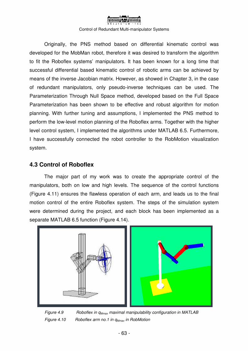
Control of Redundant Multi-manipulator Systems
- 63 -
Originally, the PNS method based on differential kinematic control was
developed for the MobMan robot, therefore it was desired to transform the algorithm
to fit the Roboflex systems’ manipulators. It has been known for a long time that
successful differential based kinematic control of robotic arms can be achieved by
means of the inverse Jacobian matrix. However, as showed in Chapter 3, in the case
of redundant manipulators, only pseudo-inverse techniques can be used. The
Parameterization Through Null Space method, developed based on the Full Space
Parameterization has been shown to be effective and robust algorithm for motion
planning. With further tuning and assumptions, I implemented the PNS method to
perform the low-level motion planning of the Roboflex arms. Together with the higher
level control system, I implemented the algorithms under MATLAB 6.5. Furthermore,
I have successfully connected the robot controller to the RobMotion visualization
system.
4.3 Control of Roboflex
The major part of my work was to create the appropriate control of the
manipulators, both on low and high levels. The sequence of the control functions
(Figure 4.11) ensures the flawless operation of each arm, and leads us to the final
motion control of the entire Roboflex system. The steps of the simulation system
were determined during the project, and each block has been implemented as a
separate MATLAB 6.5 function (Figure 4.14).
Figure 4.9 Roboflex in qMmax maximal manipulability configuration in MATLAB
Figure 4.10 Roboflex arm no.1 in qMmax in RobMotion
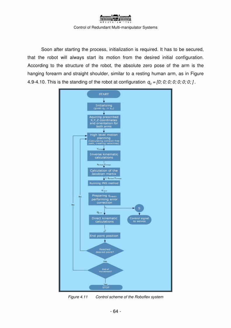
Control of Redundant Multi-manipulator Systems
- 64 -
Soon after starting the process, initialization is required. It has to be secured,
that the robot will always start its motion from the desired initial configuration.
According to the structure of the robot, the absolute zero pose of the arm is the
hanging forearm and straight shoulder, similar to a resting human arm, as in Figure
4.9-4.10. This is the standing of the robot at configuration 0q = [0; 0; 0; 0; 0; 0; 0; ] .
Figure 4.11 Control scheme of the Roboflex system

Control of Redundant Multi-manipulator Systems
- 65 -
Each arm has a configuration that holds the maximum of manipulability
according to (1.27), and can reach out to any direction. From the initial
π π π πMmaxq = [- /2; /4; 0; /2; 0; - /4; 0] configuration, it can easily move toward any point
of its workspace. The three arms are positioned within the space that considering a
0.2x0.2x0.2 metres long triangle shaped object, held by all three manipulators, their
manipulability remains the highest. Through the initialization process all three slave
arms of the system are taking the qMmax configuration from the dual-singular q0,
driven safely by joint-space commands. The centre of the workpiece is considered to
be the centre of the combined workspace, being 0.85 metres away from each arm.
Considering the actual setup of a surgery room, the robots should be higher
than the laying patient (app. 1 metre), to be able to penetrate the body through the
trocars in an optimal direction allowing the highest degree of dexterity. During
operation, the robot should be keeping its manipulability as high as possible, to keep
its path safe from singularities.
The high level motion planning layer is responsible for organising the whole
control process, creating the desired end point velocities for each movement section
according to the input desires. Once the general motion preferences are defined, the
motion planner decomposes the task to make it easier to interpolate each segment of
the path. With a given time constraint, the desired velocity can be calculated and the
number of running cycles derived. The high level motion planner is in charge of
collision detection and avoidance, meaning that it should create paths that safely
avoid collision, ensure the required motion reserve and on the other hand optimize
for speed and power efficiency. Using the inverse kinematics and direct geometric
calculations, the controller can always have an exact mapping between the 3D space
and the joint space, calculating end point coordinates to joint vectors and vice versa.
Each path segment is cut to smaller peaces depending on the desired speed,
respectively to the 10 ms cycle time. The joint velocity commands are scaled not to
overcome the 1 rad/sec limitation, to accommodate the hardware. Considering the
D-H parameters of the robot, that limit is 0.27 m/s in linear velocity. Angular velocity
is also considered during scaling.

Control of Redundant Multi-manipulator Systems
- 66 -
In every control cycle, the high level motion planner passes on to PNS the
adequate motion command in forms of end point velocities along with the Jacobian
matrix calculated from the actual joint vector derived by the inverse kinematics. The
PNS method uses these inputs to create the particular and homogenous solutions. It
optimizes the parameters according to the built-in controller to avoid singularities or
to minimize the transients. This is integrated via the means of motion preferences,
while the more strict joint limitations and restrictions are also taken into consideration
within PNS—see Chapter 3.4. The result of the PNS is a new joint velocity vector that
is needed to achieve the desired point of the path by the next cycle. Multiplying the
resulted vector by the formal ∆t parameter, the new joint parameters can be
calculated to continue the loop with. Given the required speed of the joint, the servos
can be given their control. Under real life conditions, some inaccuracy may happen
during the motion, resulting the end effector to miss a bit the prescribed position and
orientation. To compensate this–and minor errors of the differential kinematics
algorithms–an error correction term is integrated into the motion planner. It calculates
the difference between the ideal (calculated) and actual (measured) position of the
robot, and adds a correcting term to the next cycle’s motion reference vector. The
control loop operates around until the originally prescribed position and orientation is
not reached.
By the means of the closed looped control with the integrated PNS method, a
robust differential motion planning based control method has been realized. The core
of the algorithm—the PNS and the optimization within—does not run for longer than
2-3 ms, which is considered to be quick and therefore suitable to be used in case of
real time applications.
4.4 Simulation environment
The 3D visualization features of basic MATLAB 6.5 are inappropriate,
therefore a new, more characteristic and spectacular program was needed. My
choice has fallen on the RobMotion V1.2 program [5], developed by Madarász and
Petrik at the Department of Control Engineering an Information Technology - BME.
RobMotion is based on OpenGL, and able to show, move and rotate basic 3D
objects in a virtual environment. An arbitrary robot can be built from pieces of
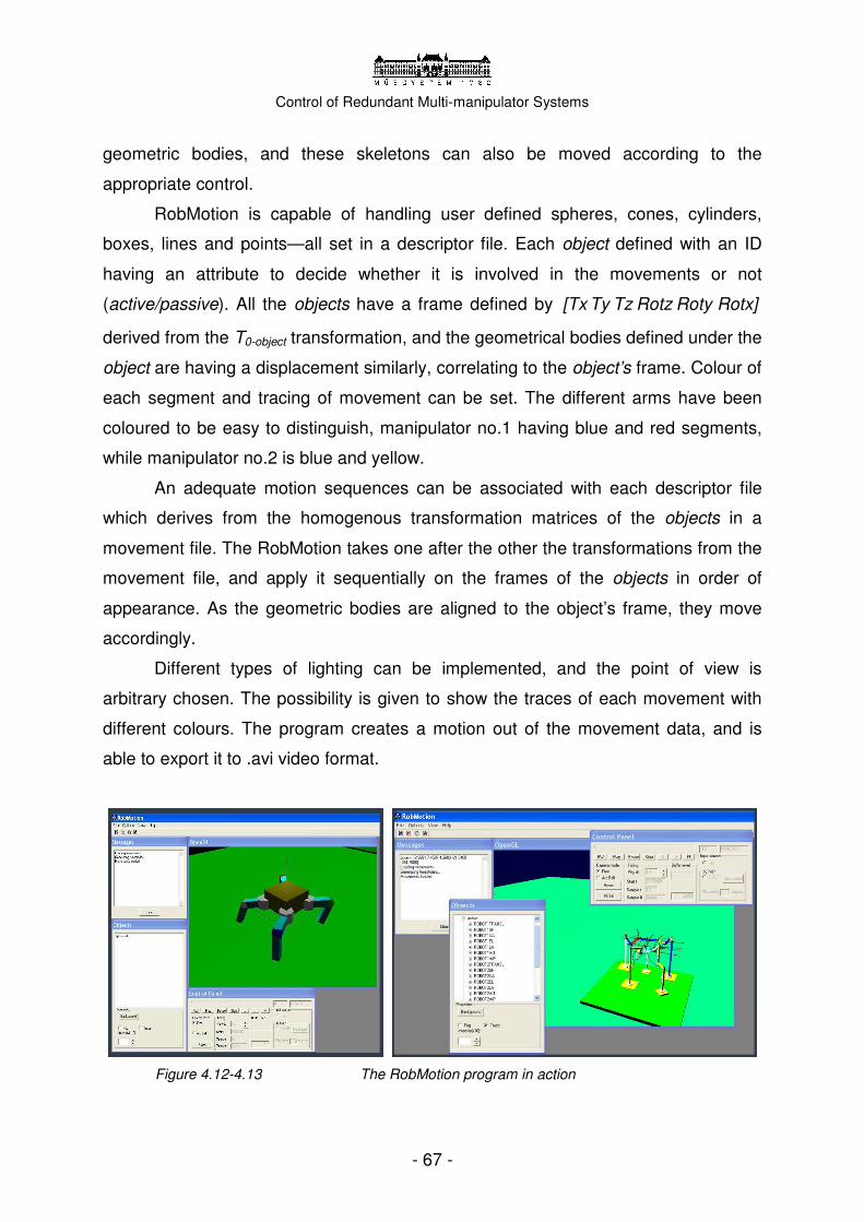
Control of Redundant Multi-manipulator Systems
- 67 -
geometric bodies, and these skeletons can also be moved according to the
appropriate control.
RobMotion is capable of handling user defined spheres, cones, cylinders,
boxes, lines and points—all set in a descriptor file. Each object defined with an ID
having an attribute to decide whether it is involved in the movements or not
(active/passive). All the objects have a frame defined by [Tx Ty Tz Rotz Roty Rotx]
derived from the T0-object transformation, and the geometrical bodies defined under the
object are having a displacement similarly, correlating to the object’s frame. Colour of
each segment and tracing of movement can be set. The different arms have been
coloured to be easy to distinguish, manipulator no.1 having blue and red segments,
while manipulator no.2 is blue and yellow.
An adequate motion sequences can be associated with each descriptor file
which derives from the homogenous transformation matrices of the objects in a
movement file. The RobMotion takes one after the other the transformations from the
movement file, and apply it sequentially on the frames of the objects in order of
appearance. As the geometric bodies are aligned to the object’s frame, they move
accordingly.
Different types of lighting can be implemented, and the point of view is
arbitrary chosen. The possibility is given to show the traces of each movement with
different colours. The program creates a motion out of the movement data, and is
able to export it to .avi video format.
Figure 4.12-4.13 The RobMotion program in action

Control of Redundant Multi-manipulator Systems
- 68 -
First and foremost, the Roboflex system’s manipulators had to be constructed
based on the Denavit-Hartenberg parameters. To avoid any further difficulties, the
robot was not scaled, all the parameters are set in metric units. The program takes
the data from the Roboflex.txt descriptor file, which contains all the active and
passive objects of the 3D environment. Upon implementing, it was critical to follow
the D-H convention of the robots, which means each segment having its frame so
that the revolute joint’s rotational axis should be around z.
The descriptor file consists of six main parts. Firstly, the initialization of the
parameters and the set of general variables can be found. The time scale
accommodates to the control algorithm’s, being 10 milliseconds, and the number of
samples determines the length of the simulation. This section also contains passive
objects, such as the grass and the background. The second, third and fourth parts
are identical 7DOF manipulators of the Roboflex system, meanwhile the fifth section
defines arm no.4–holding the camera. In the final part, the parameters of the lighting
and the position of the camera are set.
RobMotion does not include the modelling of the joints; therefore symbolic
joints have been added to the end of each segment. At the tip of the arm, a small
cylinder represents the end effector. An additional white box represents the
spring-like universal end effector. To help the visual orientation and understanding of
the motion sequences, the frames of each joint has been drawn during the test
phase. The movement specifications are taken from the movement descriptor file,
which contains step by step the pre-calculated homogenous transformation matrices
for each active object, in row format. A set of special characters closes every row in
the file. The motion data is computed by the MATLAB files, based on the PNS
method. The differential motion control calculations are performed in every 10
milliseconds (just as in the case of real life robots), and written into the actual motion
data file. The RobMotion takes one matrix for every active object in every
computational cycle, and translate and rotate its frame according to the parameters.
My programs create an effective interface between the user and the visualization,
through a set of MATLAB functions.
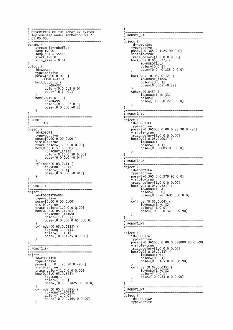
; ===================================== ; DESCRIPTOR OF THE Roboflex system ; Implemented under RobMotion V1.2 ; 09.05.06. ; ===================================== params { stream_id=roboflex samp_t=0.01 samp_num = 55555 start_t=0.0 axis_size = 0.01 } object { id=GRASS type=passive pose=[5.00 0.00 0] visible=true box(3,3,0.1) { id=GRASS1 color=[0.0 0.3 0.0] pose=[-6 1 -0.1] } box(30,40,0.1) { id=GRASS1 color=[0.0 0.7 0.1] pose=[0.0 0.0 -0.2] } } ;================================= ; ROBOT1 ; BASE ;================================= object { id=ROBOT1 type=passive pose=[0.00 0.00 0.00 ] visible=true trace_color=[1.0 0.0 0.00] box(0.5, 0.5, 0.020) { id=ROBOT_BASE1 color=[0.50 0.50 0.00] pose=[0.0 0.0 -0.04] } cylinder(0.03,0.1) { id=ROBOT1_ROT1 color=[1 1 1] pose=[0.0 0.0 -0.015] } } ;================================= ; ROBOT1_TR ;================================= object { id=ROBOT1TRANSL type=active pose=[0.00 0.00 0.00] visible=true trace_color=[1.0 0.0 0.00] box(0.05,0.05 ,1.30) { id=ROBOT1_TRANSL color=[1 1 0.5] pose=[0.0 0.0 0.65 0.0 0] } cylinder(0.05,0.0385) { id=ROBOT1_ROT331 color=[ 1 1 1] pose=[ 0 0 1.25 0 90 0] } } ;================================= ; ROBOT1_SH ;================================= object { id=ROBOT1SH type=active pose=[ 0 0 1.25 90 0 -90 ] visible=true trace_color=[1.0 0.0 0.00] box(0.05,0.05,0.365) { id=ROBOT1_SH color=[1 0 0] pose=[ 0 0 0.1825 0.0 0 0] } cylinder(0.05,0.0385) { id=ROBOT1_ROT331 color=[ 1 0 0] pose=[ 0 0 0.365 0 0 90] }
} ;========================================= ; ROBOT1_UA ;========================================= object { id=ROBOT1UA type=active pose=[-0.365 0 1.25 90 0 0] visible=true trace_color=[1.0 0.0 0.00] box(0.05,0.05,0.27) { id=ROBOT1_UA color=[0 0 1] pose=[0 0 -0.135 0 0 0] } box(0.05, 0.05, 0.12) { id=ROBOT_elbow color=[0 0 1] pose=[0 0.05 -0.29] } sphere(0.045) { id=ROBOT1_ROT331 color=[ 0 0 1] pose=[ 0 0 -0.27 0 0 0] } } ;========================================= ; ROBOT1_EL ;========================================= object { id=ROBOT1EL type=active pose=[-0.365000 0.00 0.98 90 0 -90] visible=true trace_color=[1.0 0.0 0.00] box(0.05,0.05,0.001) { id=ROBOT1_EL color=[1 1 1] pose=[0 0.0005 0 0 0 0] } } ;========================================= ; ROBOT1_LA ;========================================= object { id=ROBOT1LA type=active pose=[-0.365 0 0.979 90 0 0] visible=true trace_color=[1.0 0.0 0.00] box(0.05,0.05,0.321) { id=ROBOT1_LA color=[1 0 0] pose=[0 0 -0.1605 0.0 0 0] } cylinder(0.05,0.04) { id=ROBOT1_ROT32 color=[ 1 0 0] pose=[ 0 0 -0.321 0 0 90] } } ;========================================= ; ROBOT1_WT ;========================================= object { id=ROBOT1WT type=active pose=[-0.365000 0.00 0.658000 90 0 -90] visible=true trace_color=[1.0 0.0 0.00] box(0.05,0.05,0.33) { id=ROBOT1_WT color=[0 0 1] pose=[0 0.165 0 0.0 0 90] } cylinder(0.02,0.035) { id=ROBOT1_ROT32 color=[ 0 0 1] pose=[ 0 0.33 0 0 0 90] } } ;========================================= ; ROBOT1_WP ;========================================= object { id=ROBOT1WP type=active

Control of Redundant Multi-manipulator Systems
- 70 -
pose=[-0.365000 0.00 0.328000 90 0 0] visible=true trace_color=[1.0 0.0 0.00] box(0.04,0.04,0.03) { id=ROBOT1_END color=[0.8 0.8 0.8] pose=[0 0 -0.015 0 0 0] } line(0.1) { id=xaxis1 color=[0 1 0] pose=[0.05 0 0 0 0 0] } line(0.1) { id=yaxis1 color=[0 0 1] pose=[0 0.05 0 90 0 0] } line(0.1) { id=zaxis1 color=[1 0 0] pose=[0 0 0.05 0 -90 0] } } ;========================================= ;========================================= ;ROBOT2 ; … ; identic to Robot 1 ;========================================== ;========================================= ;========================================= ;========================================= ;ROBOT3 ; … ; identic to Robot 1 ;========================================= ;========================================== ;========================================== ;CAMERA ROBOT ;========================================== ;========================================= ; ROBOTC ; BASE ;========================================= object { id=ROBOTC type=passive pose=[-1.70 1.05 0.00 135 0 0] visible=true trace_color=[1.0 0.0 0.00] box(0.3, 0.3, 0.080) { id=ROBOTC_BASE2 color=[0.50 0.50 0.00] pose=[0.0 0.0 -0.04] } cylinder(0.02,0.1) { id=ROBOTC_ROT1 color=[1 1 1] pose=[0.0 0.0 0.045] } } ;========================================= ; ROBOTC_TR ;========================================= object { id=ROBOTCTRANSL type=passive pose=[-1.70 1.05 0 135 0 0] visible=true trace_color=[1.0 0.0 0.00] box(0.05,0.05 ,0.85) { id=ROBOTC_TRANSL color=[0.7 0.1 0.1] pose=[0.0 0.0 0.425 0.0 0] } cylinder(0.05,0.0385) { id=ROBOTC_ROT331 color=[ 1 1 1] pose=[ 0 0 0.8 0 90 0] }
} ;========================================= ; ROBOTC_SH ;========================================= object { id=ROBOTCSH type=passive pose=[ -1.7 1.05 0.8 -135 0 -90 ] visible=true trace_color=[1.0 0.0 0.00] box(0.05,0.05,0.365) { id=ROBOTC_SH color=[1 1 0] pose=[ 0 0 0.1825 0.0 0 0] } cylinder(0.05,0.0385) { id=ROBOTC_ROT331 color=[ 1 1 0] pose=[ 0 0 0.365 90 0 90] } } ;========================================= ; ROBOTC_UA ;========================================= object { id=ROBOTCUA type=passive pose=[-1.442 0.792 0.8 -135 0 0] visible=true trace_color=[1.0 0.0 0.00] box(0.05,0.05,0.27) { id=ROBOTC_UA color=[1 1 1] pose=[0 0 0.135 0 0 0] } sphere(0.045) { id=ROBOTC_ROT331 color=[1 1 1] pose=[ 0 0 0.27 0 0 0] } } ;========================================= ; ROBOTC_LA ;========================================= object { id=ROBOT2LA type=passive pose=[-1.442 0.792 1.07 -135 0 0] visible=true trace_color=[1.0 0.0 0.00] box(0.05,0.05,0.321) { id=ROBOTC_LA color=[1 1 0] pose=[0 0 0.1605 0.0 0 0] } cylinder(0.05,0.04) { id=ROBOTC_ROT32 color=[ 1 1 0] pose=[ 0 0 0.321 90 0 90] } } ;======================================== ; ROBOTC_WT ;========================================= object { id=ROBOTCWT type=passive pose=[-1.442 0.792 1.4 -135 0 -45] visible=true trace_color=[1.0 0.0 0.00] box(0.05,0.05,0.33) { id=ROBOTC_WT color=[1 1 1] pose=[0 0.165 0 0.0 0 90] } cylinder(0.02,0.035) { id=ROBOTC_ROT32 color=[1 1 1] pose=[ 0 0.33 0 0 0 90] } cone(0.07,0.07,0.02) { id=ROBOTC_END

Control of Redundant Multi-manipulator Systems
- 71 -
color=[0.8 0.8 0.8] pose=[0 0.37 0 0 0 90] } } ;========================================== ;WORKSPACE ;========================================== ;========================================= ; DESK ;========================================= object { id=DESK type=passive pose=[-0.8500 0 0.0 0 0] visible=true trace_color=[1.0 0.0 0.00] box(0.3, 0.3, 0.020) { id=DESK_BASE1 color=[0.50 0.50 0.00] pose=[0.0 0.0 -0.04] } cylinder(0.015,0.1) { id=DESK_1 color=[1 1 1] pose=[0.0 0.0 -0.015] } box(0.03,0.03 ,0.8) { id=ROBOT3_TRANSL color=[1 1 0.8] pose=[0.0 0.0 0.4 0.0 0] } box(0.25, 0.25, 0.020) { id=DESK_TOP color=[0.8 0.8 0.8] pose=[0.0 0.0 0.8] } }
;========================================= ; Workpiece ;========================================= object { id=DESK type=active pose=[-0.75 0. 0.85 90 0 90] visible=true trace_color=[1.0 0.0 0.00] box(0.18, 0.1, 0.1) { id=DESK_TOP color=[0 0.9 0.4] pose=[0 -0 -0.1 0 -90 0] } } light { id = LIGHT1 type = spot intensity = [1.0 1.0 1.0] pose = [6 6 6 -135 -135 40] } light { id = LIGHT2 type = spot intensity = [1.0 1.0 1.0] pose = [3 3 3 -135 -135 40] } light { id = LIGHT3 type = dir intensity = [.8 .8 .8] pose = [0 0 20 -180 -130 40 ] } camera { pose = [-1.7142 -2.7754 2.1910 -27.4200 -77.3234] }
; ============================================================================= ; SAMPLE OF A MOVEMENT FILE FOR THE Roboflex system ; Implemented under RobMotion V1.2 ; 09.05.06. ; ============================================================================= roboflex -1.000000 -0.000000 0.000000 -1.700000 0.000000 -1.000000 0.000000 0.000000 0.000000 0.000000 1.000000 0.000000 1 2 2 2 -0.000000 0.000000 1.000000 -1.700000 -1.000000 -0.000000 -0.000000 0.000000 0.000000 -1.000000 0.000000 1.250000 1 2 2 2 -0.000000 1.000000 0.000000 -1.335000 -1.000000 -0.000000 0.000000 -0.000000 0.000000 0.000000 1.000000 1.250000 1 2 2 2 -0.000000 0.000000 1.000000 -1.335000 -1.000000 -0.000000 -0.000000 -0.000000 0.000000 -1.000000 0.000000 0.980000 1 2 2 2 -0.000000 1.000000 0.000000 -1.335000 -1.000000 -0.000000 0.000000 -0.000000 0.000000 0.000000 1.000000 0.979000 1 2 2 2 -0.000000 0.000000 1.000000 -1.335000 -1.000000 -0.000000 -0.000000 -0.000000 0.000000 -1.000000 0.000000 0.658000 1 2 2 2 -0.000000 1.000000 0.000000 -1.335000 -1.000000 -0.000000 0.000000 -0.000000 0.000000 0.000000 1.000000 0.328000 1 2 2 2 -1.000000 -0.000000 0.000000 -1.700000 0.000000 -1.000000 0.000000 0.000000 0.000000 0.000000 1.000000 0.000000 1 2 2 2 -0.000000 0.000000 1.000000 -1.700000 -1.000000 -0.000000 -0.000000 0.000000 0.000000 -1.000000 0.000000 1.250000 1 2 2 2 -0.000000 1.000000 0.000000 -1.335000 -1.000000 -0.000000 0.000000 -0.000000 0.000000 0.000000 1.000000 1.250000 1 2 2 2 -0.000000 0.000000 1.000000 -1.335000 -1.000000 -0.000000 -0.000000 -0.000000 0.000000 -1.000000 0.000000 0.980000 1 2 2 2 -0.000000 1.000000 0.000000 -1.335000 -1.000000 -0.000000 0.000000 -0.000000 0.000000 0.000000 1.000000 0.979000 1 2 2 2 -0.000000 0.000000 1.000000 -1.335000 -1.000000 -0.000000 -0.000000 -0.000000 0.000000 -1.000000 0.000000 0.658000 1 2 2 2 -0.000000 1.000000 0.000000 -1.335000 -1.000000 -0.000000 0.000000 -0.000000 0.000000 0.000000 1.000000 0.328000 1 2 2 2 -0.999969 -0.007854 0.000000 -1.700000 0.007854 -0.999969 0.000000 0.000000 0.000000 0.000000 1.000000 0.000000 1 2 2 2 -0.007854 0.000031 0.999969 -1.700000 -0.999961 0.003927 -0.007854 0.000000 -0.003927 -0.999992 0.000000 1.250000 1 2 2 2 -0.007854 0.999969 -0.000031 -1.335011 -0.999961 -0.007854 -0.003927 -0.002867 -0.003927 0.000000 0.999992 1.250000 1 2 2 2 -0.007853 0.000093 0.999969 -1.335003 -0.999900 0.011780 -0.007854 -0.001806 -0.011781 -0.999931 0.000000 0.980002 1 2 2 2 -0.007853 0.999969 -0.000093 -1.335003 -0.999900 -0.007854 -0.011780 -0.001795 -0.011781 0.000000 0.999931 0.979002 1 2 2 2 -0.007854 0.000062 0.999969 -1.334973 -0.999938 0.007854 -0.007854 0.001987 -0.007854 -0.999969 0.000000 0.658024 1 2 2 2 0.023560 0.999722 -0.000062 -1.334953 -0.999692 0.023559 -0.007854 0.004579 -0.007850 0.000247 0.999969 0.328035 1 2 2 2 -0.999877 -0.015707 0.000000 -1.700000 0.015707 -0.999877 0.000000 0.000000 0.000000 0.000000 1.000000 0.000000 1 2 2 2 -0.015707 0.000123 0.999877 -1.700000 -0.999846 0.007853 -0.015707 0.000000 -0.007854 -0.999969 0.000000 1.250000 1 2 2 2 -0.015707 0.999877 -0.000123 -1.335045 -0.999846 -0.015707 -0.007853 -0.005733 -0.007854 0.000000 0.999969 1.250000 1 2 2 2 -0.015703 0.000370 0.999877 -1.335012 -0.999599 0.023557 -0.015707 -0.003613 -0.023560 -0.999722 0.000000 0.980008 1 2 2 2 -0.015703 0.999877 -0.000370 -1.335011 -0.999599 -0.015707 -0.023557 -0.003589 -0.023560 0.000000 0.999722 0.979009 1 2 2 2 -0.015705 0.000247 0.999877 -1.334893 -0.999753 0.015705 -0.015707 0.003972 -0.015707 -0.999877 0.000000 0.658098 1 2 2 2 0.047108 0.998890 -0.000247 -1.334811 -0.998767 0.047099 -0.015705 0.009155 -0.015676 0.000986 0.999877 0.328138 1 2 2 2 -0.999722 -0.023560 0.000000 -1.700000 0.023560 -0.999722 0.000000 0.000000 0.000000 0.000000 1.000000 0.000000 1 2 2 2 -0.023558 0.000278 0.999722 -1.700000 -0.999653 0.011777 -0.023560 0.000000 -0.011781 -0.999931 0.000000 1.250000 1 2 2 2 -0.023558 0.999722 -0.000278 -1.335101 -0.999653 -0.023560 -0.011777 -0.008599 -0.011781 0.000000 0.999931 1.250000 1 2 2 2 -0.023545 0.000832 0.999722 -1.335026 -0.999098 0.035326 -0.023560 -0.005419 -0.035336 -0.999376 0.000000 0.980019 1 2 2 2 -0.023545 0.999722 -0.000832 -1.335026 -0.999098 -0.023560 -0.035326 -0.005384 -0.035336 0.000000 0.999376 0.979019 1 2 2 2 -0.023553 0.000555 0.999722 -1.334758 -0.999445 0.023553 -0.023560 0.005955 -0.023560 -0.999722 0.000000 0.658220 1 2 2 2 0.070633 0.997502 -0.000555 -1.334575 -0.997227 0.070601 -0.023553 0.013728 -0.023455 0.002217 0.999722 0.328311 1 2 2 2 -0.999507 -0.031411 0.000000 -1.700000 0.031411 -0.999507 0.000000 0.000000 0.000000 0.000000 1.000000 0.000000 1 2 2 2 -0.031407 0.000493 0.999507 -1.700000 -0.999383 0.015700 -0.031411 0.000000 -0.015707 -0.999877 0.000000 1.250000 1 2 2 2 -0.031407 0.999507 -0.000493 -1.335180 -0.999383 -0.031411 -0.015700 -0.011465 -0.015707 0.000000 0.999877 1.250000 1 2 2 2 -0.031376 0.001480 0.999507 -1.335047 -0.998397 0.047083 -0.031411 -0.007226 -0.047106 -0.998890 0.000000 0.980033 1 2 2 2 -0.031376 0.999507 -0.001480 -1.335045 -0.998397 -0.031411 -0.047083 -0.007179 -0.047106 0.000000 0.998890 0.979034 1 2 2 2 -0.031395 0.000987 0.999507 -1.334570 -0.999013 0.031395 -0.031411 0.007935 -0.031411 -0.999507 0.000000 0.658391 1 2 2 2 0.094124 0.995560 -0.000987 -1.334245 -0.995073 0.094046 -0.031395 0.018295 -0.031163 0.003937 0.999507 0.328554 1 2 2 2
; =================================================== ; END OF MOVEMENT ; ===================================================
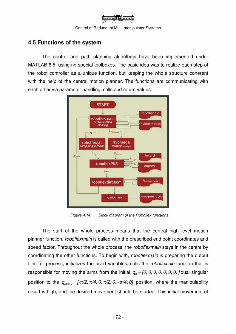
Control of Redundant Multi-manipulator Systems
- 72 -
4.5 Functions of the system
The control and path planning algorithms have been implemented under
MATLAB 6.5, using no special toolboxes. The basic idea was to realize each step of
the robot controller as a unique function, but keeping the whole structure coherent
with the help of the central motion planner. The functions are communicating with
each other via parameter handling, calls and return values.
Figure 4.14 Block diagram of the Roboflex functions
The start of the whole process means that the central high level motion
planner function, roboflexmain is called with the prescribed end point coordinates and
speed factor. Throughout the whole process, the roboflexmain stays in the centre by
coordinating the other functions. To begin with, roboflexmain is preparing the output
files for process, initializes the used variables, calls the roboflexinic function that is
responsible for moving the arms from the initial 0q = [0; 0; 0; 0; 0; 0; 0; ] dual singular
position to the π π π πMmaxq = [- /2; /4; 0; /2; 0; - /4; 0] position, where the manipulability
resort is high, and the desired movement should be started. This initial movement of

Control of Redundant Multi-manipulator Systems
- 73 -
the three arms is driven by joint space defined motion to keep the robot safe from
singularities.
The roboflexmain’s most important job is to create the adequate path
segments through which the robot will be guided to reach the prescribed end point. If
needed, there is a possibility to break up the path to smaller parts, and to interpolate
with different curves, always having in mind the desire to avoid any kind of collision. It
performs calculations and gives commands to all three robot arms, but excluding the
fourth manipulator, holding the endoscopic camera. The preparation of the control
signals is parallel. Cooperative manipulation tasks can be brought to fruition in a
centralized way.
Using the invkinematics function, the coherent joint vector can be calculated
for a given end point position and orientation, to help the motion planner to create the
paths. The spherical joint transformation method, developed by Dahm et al.
introduced in (3.6) is used to resolve the redundancy of the Roboflex arms. The
Upper Arm and the Elbow joints are suitable to be substituted by a 2DOF
azimuth-elevation represented joint, as their axes are perpendicular and have no
offset in between. The representation, the calculations can be derived back to a
6DOF case using a closed-formula solution. The roboflexmain calls on one hand the
roboflexjac that calculates the Jacobian matrix of the robot for each joint vector, and
rfvomega on the other hand to determine the desired end point velocities from the
given path segment’s end point. The resulting Jq and Vomega are the input
parameters–along with the qactual–for the PNS method, which is realized in the
roboflexPNS function.
RoboflexPNS executes the previously introduced steps (1.35)-(1.47), and
creates firstly the particular solution for the desired motion. To deal with
ill-conditioned matrices, an SVD based inversion method has been implemented in
the function invertt that considers the condition number of the given matrix as well,
and performs minor correction according to (1.48), if the matrix is ill-conditioned and
could cause troubles upon transformations. The calculation of the homogenous term
is performed by the qoptim function that has a built-in controller to choose from the
different solutions of the solution sub-space. Considering motion preferences, it
performs the closed-form optimization according to (1.49), minimizing transients and
securing the motion of the manipulator near singularities. The preferred configuration

Control of Redundant Multi-manipulator Systems
- 74 -
is calculated with the Bochum method (see Chapter 3.5), and the prescribed values
are �i,dq = [-0.1; -1.26268; -1.44146; - 0.878143; - 0.396075; 1.14495; -1.144856] .
Each parameter of the P term saturation controllers are set based on
experiments. The width parameters are [ ]w = 0.1 0.1 0.1 0.1 0.1 0.1 0.1
meaning that all joint preferences are handled equally in time, and height parameters
are set to [ ]h = 1 1 1 1 0 0 0 meaning that the motion preferences are applied
on the first four joints, leaving alone the last three. This solution is preferred, as the
shoulder, elbow and upper arm joints are mostly able to keep motion reserve thanks
to the kinematic redundancy. I have also realized the interface for motion restrictions
(1.50-1.51) that have to be met during the task execution, however, it is not used in
the given example.
The roboflexPNS function results a new q vector that will ensure the desired
movement. The roboflexdirgeom performs direct geometric calculations, to determine
the end point’s new position and orientation, using the separately realized
homogenous transformation functions, transl, rotx, roty and roty. It is roboflexdirgeom
that calls for the outsource function to fill the movement.txt file with the appropriate
forms of the transformation matrices for visualization in RobMotion. This file could be
considered as an output for real effectors, servos and motors.
The next position is looped back to the roboflexmain function to let the
algorithm running along with the desired values in the next cycle. After each cycle,
the central motion planner calculates the resulting position error of the PNS method
and the hardware, meanwhile by adding a correction term to the next prescribed
velocity vector, it compensates the error and does not let it to accumulate. Having
finished the movement-reached the desired pose-the roboflexmain ends the process
and quits. The resulted motion is documented in the movement file, and other
optional parameters (for analyzing purposes) can also be registered and regained
from .txt files after running.
4.6 Numeric results
The original idea of the project was to perform and simulate a complete surgical
task–such as suturing–with the new robotic system, Roboflex; however it soon turned

Control of Redundant Multi-manipulator Systems
- 75 -
out that the preparation of a life-like example would exceed the scale of the Diploma
and would require a medical doctor’s assistance. Lacking any surgical consultant, a
more general cooperative work piece manipulation task was picked to show the
capabilities of the system.
The chosen task was the manipulation of a box, which requires the close
cooperation of the two arms. The initial position of the target box is at 0.9 metres
altitude, which can be considered to be the level of a surgery desk. Starting the
simulation, the robot arms first take their π π π πMmaxq = [- /2; /4; 0; /2; 0; - /4; 0]
positions, and perform the following movement: approach of the target along a safe
path, optimizing for a maximum of manipulability. Secondly, they virtually grab the
object. (The white cones at each robot’s end (Figure 4.4) should be considered as
springs or other end effectors to grab an item.) Afterward the two manipulators
perform a circular movement, showing the possibilities in redundancy as the robots
can still perform different joint movements with a fixed end point. Finally, the
manipulators replace the object and after a slow detach, they return to their original
positions. Altogether the motion is realized in 4300 motion cycles, and lasts for 43
seconds. Screenshots can be seen from the movements on Figures 15-29.
The used functions with the matching parameter settings can be found on the
supplementary CD-ROM, in the /source folder. The visualization of the simulation has
resulted the rf_pns1.avi video in /results/complex/. (The example task has been
recorded from several points of view.)
Figure 4.15-4.20 Motion sequence of the test case I.

Control of Redundant Multi-manipulator Systems
- 76 -
Figure 4.21-4.29 Motion sequence of the test case II.
The example motion was simulated by using the PNS method for low level
motion planning and the simple pseudo-inverse algorithm as well. It can be seen on
the rf_pszeudo.avi video (/results/complex/), that the resulting motion is less smooth,
and by measuring the manipulability reserve through each motion cycle it can be
determined, that the PNS method optimizes for greater manipulability. The second
arm’s average manipulability for the whole motion derived to be 0.049968 using PNS
and 0.044693 using the pseudo-inverse method. The manipulability reserve of the
entire system was 4% bigger using PNS (/results/manipulability/manipulability.xls).
Figure 4.30 plots the manipulability measure against time throughout the entire
example motion. The blue curve belongs to the arm no.1 and the yellow to arm no.2.
Significant configurations are displayed. It can be seen that high manipulability
belongs to configurations where the robot’s elbow is flexed and the joint variables are
close to the values qMmax, while the manipulability decreases dramatically, if a robot
stretches to one direction.

Control of Redundant Multi-manipulator Systems
- 77 -
Let us go through a motion cycle in more details to present the actual
mechanism of the algorithm. To make a clear case, we can choose the first motion
step of an arbitrary task execution, when the manipulators start to retract from the
π π π πMmaxq = [- /2; /4; 0; /2; 0; - /4; 0] pose. Calculations will only be shown for the no.1
arm (blue and red, on the right hand side).
Figure 4.30 Manipulability measure for both arms throughout the example motion
The robot’s end point is in the startX = [-0.7486; 0.3650; 1.2868] position, with the
initial orientation. Firstly, the desired end point is given to the algorithm
desX = [0.12; 0.66; 1.8] , with the orientation o = [-0.4; 0; 0] and a speed scale being
500. The central motion planner is given the desired end point velocities after having
cut the path to 500 segments p_desX = [-0.02; - 0.11; 0.3; - 0.4; 0; 0] . The Jacobian
matrix for the robot in the given configuration being respectively
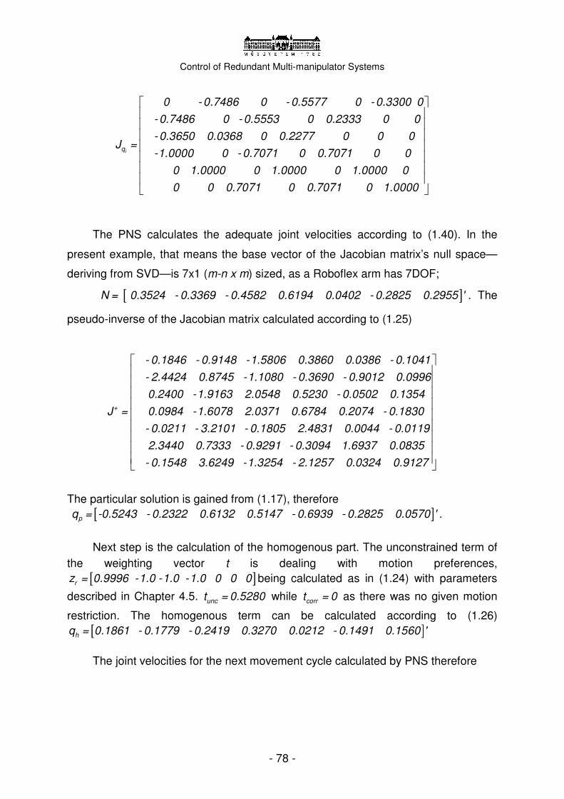
Control of Redundant Multi-manipulator Systems
- 78 -
iq
0 - 0.7486 0 - 0.5577 0 - 0.3300 0
- 0.7486 0 - 0.5553 0 0.2333 0 0
- 0.3650 0.0368 0 0.2277 0 0 J =
0
-1.0000 0 - 0.7071 0 0.7071 0 0
0 1.0000 0 1.0000 0 1.0000 0
0 0 0.7071 0 0.7071 0 1.0000
The PNS calculates the adequate joint velocities according to (1.40). In the
present example, that means the base vector of the Jacobian matrix’s null space—
deriving from SVD—is 7x1 (m-n x m) sized, as a Roboflex arm has 7DOF;
[ ]N = 0.3524 - 0.3369 - 0.4582 0.6194 0.0402 - 0.2825 0.2955 ' . The
pseudo-inverse of the Jacobian matrix calculated according to (1.25)
+
- 0.1846 - 0.9148 -1.5806 0.3860 0.0386 - 0.1041
- 2.4424 0.8745 -1.1080 - 0.3690 - 0.9012 0.0996
0.2400 -1.9163 2.0548 0.5230 - 0.0502 0.1354
J = 0.0984 -1.6078 2.0371 0.6784 0.2074 - 0.1830
- 0.0211 - 3.2101 - 0.1805 2.4831 0.0044 - 0.0119
2.3440 0.7333 - 0.9291 - 0.3094 1.6937 0.0835
- 0.1548 3.6249 -1.3254 - 2.1257 0.0324 0.9127
The particular solution is gained from (1.17), therefore [ ]pq = -0.5243 - 0.2322 0.6132 0.5147 - 0.6939 - 0.2825 0.0570 ' .
Next step is the calculation of the homogenous part. The unconstrained term of the weighting vector t is dealing with motion preferences,
[ ]rz = 0.9996 -1.0 -1.0 -1.0 0 0 0 being calculated as in (1.24) with parameters
described in Chapter 4.5. unct = 0.5280 while corrt = 0 as there was no given motion
restriction. The homogenous term can be calculated according to (1.26) [ ]hq = 0.1861 - 0.1779 - 0.2419 0.3270 0.0212 - 0.1491 0.1560 '
The joint velocities for the next movement cycle calculated by PNS therefore

Control of Redundant Multi-manipulator Systems
- 79 -
� � �next part homg
- 0.5243 0.1861
- 0.2322 - 0.1779
0.6132 - 0.2419
q = q + q = 0.5147 + 0.3270
- 0.6939 0.0212
- 0.2825 - 0.1491
0.0570 0.1560
- 0.3382
- 0.4100
0.3713
= 0.8417
- 0.6726
- 0.4317
0.2131
;
Meanwhile, the results with the pseudo-inverse end up with the joint derivate
vector �p-iq = [-0.5243 - 0.2322 0.6132 0.5147 - 0.6939 - 0.2825 0.0570]' .
Multiplying the joint velocities nominally by the cycle time ∆t and adding to the
previous joint coordinates, the next joint coordinates are gained
�PNS_nextq = [-1.5948 0.8156 - 0.0406 1.5055 0.1473 - 0.7789 0.1147]' .
Solving the direct geometric task, the new end point position can be easily calculated
07
PNS
0.0552 0.1459 0.9878 - 0.7487
0.1855 0.9705 - 0.1537 0.4390T =
- 0.9811 0.1917 0.0265 1.2756
0 0 0 1.0000
[ ]PNS_newX = -0.7487 0.4390 1.2756
With the use of pseudo-inverse method new_p-iX = [-0.7456 0.3639 1.2870]
would have been the result. It can be seen that using the pseudo-inverse method
results larger error rate derived from the Xerr = Xi,des - Xnew; being
i,desX = [-0.7488 0.4361 1.2960] . The PNS proved to be more adequate for motion
control thanks to its criteria and preference optimization.
To present the functioning of motion preferences, identical end point positions
and orientations were given to the robots, but with different motion preferences. In
case 1, �i,dq = [-0.1; -1.26268; -1.44146; - 0.878143; - 0.396075; 1.14495; -1.144856]
was set, meaning that the robot aspires to maximize its manipulability reserve. The
resulting movement can be found in video file rf_motionpref1.avi
(/results/motion_pref/). However, if we change the reference motion, even only for the

Control of Redundant Multi-manipulator Systems
- 80 -
elbow joint, �4,dq = [0.878143] the resulting configuration will be entirely different after
5 seconds (500 motion cycles); rf_motionpref2.avi. The third case shows another
reference given for only the Tower Rotation joint; �1,dq = [-1.1] resulting that the robot
rotates to the preferred direction, meanwhile the other joint are trying to stretch, and
the end effector does not move a bit. It can be seen in rf_motionpref3.avi. The robots
are using their spare manipulability originating from redundancy to satisfy the motion
preferences.
Figure 4.30-4.32 Motion preferences with identical end point prescriptions
The mechanism of the Roboflex control has been shown through one complex
manipulation task example. The algorithm could derive in each cycle the desired joint
velocities from the Jacobian matrix and the prescribed end point velocities in null
space. The high and the low level motion planning algorithms have been successfully
integrated into one control project.
The virtual 3D model of the Roboflex system was implemented and constructed
under RobMotion, and an interface was developed to transform the computed
matrices to a more spectacular motion visualization. The control system is able to
handle straight-forward simple motion preferences, and can be used for motion
planning of the complete Roboflex system.

Control of Redundant Multi-manipulator Systems
- 81 -
4.7 Future work
There are some aspects of my Diploma work that could be laboured more
detailed, fine tuned or made more sophisticated. The original goals have been met,
and along the given paths, it is possible to continue the work by defining new aims.
Further development could exceed the Diploma’s scale, and serve as a basis for
sophisticated scientific research. The realized PNS based differential kinematical
motion planning core of the algorithm can be considered to be complete; in the future
it could be better integrated into the high level motion planner. By making some
architectural changes, a middle level motion planner could be added to take over
some tasks from the higher level, and make it more effective. General path planning,
curve fitting and slicing is an ever widening field of control engineering, newer and
more advanced solutions could be implemented in the middle layer and tested. In the
mean time, the third arm should also be involved in the task execution processes.
There could be advantageous motion patterns using all three manipulators actively.
It would be appropriate to implement the three layered collision detection
algorithm proposed by Kemény and Lantos and presented in Chapter 3.7. Upon
realization, some processing optimization should be made to fit into the 5-6 ms
timeframe given for control computation in real life applications.
The low level motion planning can be considered complete, however there is
the possibility to fine tune the controller and criterion function be used in the
calculation of the homogenous term. By adding some complex constraint functions,
probably smoother motion can be attained.
The actual object manipulation problem presented does not reveal all the
capabilities of the PNS method. A more thorough example should be set to give a
worthy demonstration of the developed Roboflex system. With the cooperation of
trained surgeons, a general surgical procedure could be modelled, focusing on the
presumably automatable sections of the operation, such as suturing. The problem
statement, motion equations and a unique solution can be found in Kang’s
thesis [23]. Roboflex system could be tested with a series of suing and knot tying
procedures.

Control of Redundant Multi-manipulator Systems
- 82 -
In the future ahead of us—by investing into a greater project—a physical
manifestation of the Roboflex system could be built, presenting either already
realized manipulators, or manifesting the structures developed within the frame of
this Diploma work. Obviously, a real life robotic system has to meet much stricter
requirements, let alone performing in medical applications. The possibility is given to
ameliorate Roboflex into an effective and practical tool that makes the life of
professionals easier and gives place to conduct further researches.

Control of Redundant Multi-manipulator Systems
- 83 -
Conclusion
The tremendous effort invested in the world-wide development of advanced
robotic arms seems to return. Manipulator systems are already capable of solving
several complex tasks, and the directions of further researches are clear. The aim is
to invent more flexible, fully autonomous, multi-functional robotic arms to provide a
reliable partner for industrial applications, medical procedures and space exploration.
In this Diploma thesis I have given a thorough introduction of two special fields
of application of redundant systems, space robotics and surgical robotics. In both
applications, the extreme physical and safety requirements pose a great challenge to
the designers, and the cruxes of the control have not been solved universally. The
bright concept of using multiple arms have been implemented quite early, and the
existing systems are profiting from the architecture’s dexterity and flexibility.
The most important space and surgical robots have been presented, and an
attempt was made to summarize their achievements. I have ventured to outline the
directions of present day’s researches and to spot the imperfections of the presented
systems–along with their advantages. Assumptions were made how to ameliorate
further the quality, avail and universality of these extreme robots.
The middle part of the thesis dealt with the different control algorithms
developed for low level motion control of redundant manipulators. Several algorithms
have been presented, and three were examined in more details. Pseudo-inverse
method can resolve the built-in redundancy, but does not make use of the additional
flexibility of the robot, therefore not preferred in real applications. Full Space
Parameterization and Parameterization Through Null Space algorithms are both
combining multiple techniques to handle motion preferences and constraints as well.
A thorough numerical comparison test showed that the PNS has several advantages

Control of Redundant Multi-manipulator Systems
- 84 -
over FSP; not only in complexity and computational efficiency, but in the terms of
actual solutions as well.
Considering high level motion planning, decoupling methods have been
presented, and the topic of collision detection has been discussed, focusing on a
three-layer architecture.
Within the frames of the Diploma work I have successfully planned and
realized the Roboflex general purpose medical robotic system. Roboflex was
designed based on real robotic systems, and several theoretical cogitations were
made to create the Denavit-Hartenberg parameters.
Effective controller of the manipulators was designed, using the
Parameterization Through Null Space method for low level motion planning under
MATLAB 6.5. The differential kinematics based PNS algorithm’s main feature is that
it uses Moore-Penrose pseudo-inverse and subsidiary optimization criteria to resolve
redundancy. The advantages of the PNS have been widely exploited.
The low level motion planning has been successfully attached to the higher
level control, and all the MATLAB functions could fit in a common control scheme.
During path planning, collision avoidance and manipulability optimization were
considered to determine the desired path. A concrete manipulation task was
introduced, involving multiple arms, and effectively attaching the low and high level
motion controllers.
To visualize the results, the MATLAB generated data was transferred to the
OpenGL based RobMotion simulation environment. The complete 3D model of the
Roboflex system was constructed in RobMotion, and through a developed interface,
the motions of the system could be spectacularly visualized.
In summary, it can be stated that the further improvement of the control of
redundant manipulators pushes the conquest of new frontiers. These robotic
structures acquiring several advantages on classical 6DOF arms can also be used
under extreme requirements. The general aim is to create a universal control scheme
that suits all the different mechanics. As a result of the Diploma work, I have
designed a new concept for a surgical robot–named Roboflex. Hardware scheme and
control software were designed alike. The advantages of the PNS method over the

Control of Redundant Multi-manipulator Systems
- 85 -
FSP and other techniques have been shown. The algorithms have been tested and
verified, providing a new complex controller for redundant manipulators. In the not too
distant future, these dexterous robotic complexes will take the lead and help us
proceed to a new era.

Control of Redundant Multi-manipulator Systems
- 86 -
Appendix
Supplementary CD-ROM
A supplementary CD-ROM is attached to the Diploma thesis providing all the
necessary source files, simulation results, motion videos and additional materials.
With the help of these codes, it is possible to reproduce the results presented.
References have been put along the text to make the navigation easier, and
the following short description intends to give further guidance.
\diploma_haidegger ..\additional_materials ..\pictures ..\references ..\further_references ..\support ..\RobMotion ..\VLC media player ..\Adobe ..\documentation ..\results ..\complex ..\manipulability ..\motion_pref ..\source ..\complex ..\manipulability ..\motion_pref
Probably the most important materials are the source codes located in \source
folder. One can find there all the MATLAB 6.5 functions and RobMotion files of the
general Roboflex system. The modified functions related to the special cases referred
to in Chapter 4 are organized into subfolders, named accordingly. Each folder
contains all the functions plus a Readme.txt file containing further instructions.
The actual numeric results, motion files and rendered videos are located in
\results, with similar structure to \source.
Folder \documantation contains the Diploma thesis in .pdf format.
Under \additional_materials the electronically available references can be
found along with further publications related to the thesis. A selection of additional
pictures is also available under \pictures. The \support folder contains the necessary
programs to run the simulations, view the videos and read the documentation.

Control of Redundant Multi-manipulator Systems
- 87 -
References
[1] Zsolt Kemény: Kinematic Modeling and Low-Level Motion Planning for Redundant
and Mobile Robots, PhD Thesis, 2003
[2] U. Sezgin: Utilization of Manipulator Redundancies for Collision Avoidance
Strategies, PhD Thesis, 1995
[3] Zs. Kemeny, B. Lantos: Design and Evaluation Environment for Collision-Free Motion
Planning of Cooperation Robots; Proceeding of the International Conference on
Intelligent Engineering Systems, 1999
[4] G. A. Fries, C. J. Hacker, F. G. Pin: FSP (Full Space Parameterization) Version 2.0;
Oak Ridge National Laboratory, Technical Report, 1995
[5] T. Haidegger: Flexibilis Multi-Manipulátor Rendszerek Irányítása; TDK paper;
BME-VIK, 2005
[6] A. Madarász, G. Petrik: RobMotion mozgásvizuáló program, Dokumentáció; BME,
2004
References on robot control
[7] B. Lantos, Robotok irányítása, Akadémia Kiadó, 2001.
[8] J. Somló, B. Lantos, Cat: Advanced Robot Control, Akadémia Kiadó, 1997
[9] Murray, Li, Sastry: A Mathematical Introduction to Robotic Manipulation, CRC Press,
1994
[10] Canudas de Wit, B. Siciliano, D. Bastin; The ZODIAC: Theory of Robot Control,
Springer, 1996
[11] S. Russel, P. Norwig. Artificial Intelligence: A Modern Approach, Prentice Hall, 1995
References on space robotics
[12] H. Xie: Real-time cooperative control of a dual-arm redundant manipulator system;
PhD Thesis, 2001
[13] H. Xie, I. J. Bryson, F Shadpey, R.V. Patel: A Robust Control Scheme for Dual-Arm
Redundant Manipulators: Experimental Results, Proceedings of the IEEE Intl.
Conference of Robotics and Automation; Detroit, Michigan, 1999
[14] A. Ellery: Introduction to Space Robotics, Springer, 2000

Control of Redundant Multi-manipulator Systems
- 88 -
[15] T. Haidegger: Advanced Robotic Arms in Space; Proceedings of the 55th International
Astronautical Congress - Vancouver, Canada, 2004.
[16] Couwenberg, Lieuw, Schulten: The ERA Simulation Facility for the European Robotic
Arm Programme; 1999
[17] U.G. Termote, D.J. Schulten, R.M. Lieuw, M.J.H. Couwenberg: Eurosim and its
Applications on the European Robotic Arm Programme; Dedicated Systems
Magazine, 2000
[18] Humans and Robots; NASA Educational Brief, 2001
[19] D. W. Meer, S. M. Rock: Experiments in Object Impedance Control for Flexible Object
References on surgical robotics
[20] E. Dombre: Introduction to Surgical Robotics, Montpellier, 2005
[21] Taylor, Stoianovici: Medical Robotics in Computer-Integrated Surgery; IEEE
Transaction on Robotics and Automation, Vol. 19, 2003
[22] Speich, Rosen: Medical Robotics; In Encyclopedia of Biomaterials and Biomedical
Engineering, Marcel Dekker, 2004
[23] H. Kang: Robotic Assisted Suturing in Minimally Invasive Surgery, Thesis at
Rensellear Polytechnic Institute, 2002
[24] G. S. Rogers, C. G. L. Cao: Computer-Enhanced Instruments: The next Generation of
Surgical Robots; Ballantyne, 2004
[25] R. Howe, Y. Matsuoka: Robotics for Surgery, Annual Review of Biomedical
Engineering, 1999
[26] B. Davies: A review of robotics on surgery, Proceedings of Instn Mech Engrs, Vol.
214, 1999
[27] G.Duchemin, E. Dombre, F. Pierrot, E. Dégoulange: SCALPP:. A 6-DOF robot with a
non-spherical wrist for surgical applications; Advances in Kinematics: Robotics and
Control, 2000
[28] L. Gaspadi, N. Di Lorenzo: State of the Art of Robotics in General Surgery, Business
Briefing: Global Surgery, 2003
[29] H. Mayer, I. Nagy, A. Knoll, EU Schirmbeck & R. Bauernschmitt: Upgrading
Instruments for Robotic Surgery, Proceedings of ACRA, 2004
[30] W. T. Ang: Active Tremor Compensation in Handheld Instrument for Microsurgery,
Thesis at Nanyang Technological University, 2004
[31] D. Bratanov, T. Dobrev, M. Mladenov, P. Vitliemov: Technical documentation of the
non-commercial part of the 3D motion therapy monitoring system – RehaRob; 2001
Control of Redundant Multi-manipulator Systems
- 89 -
Further references
[32] Kapor, Tesar: Intelligent Robotic System and Control Software, 2005
[33] Ahuactzin, Gupta: A motion planning based approach for inverse kinematics of
redundant robots: the kinematic roadmap
[34] H. Seraji, M. Long, T. Lee: Motion control of 7 DOF arms: The configuration control
approach, IEEE Transactions on Robotics and Automation, 1993
[35] Nguyen, Walker: Dinamic control of flexible kinematically redundant robot
[36] Jankowski, El Maraghy: Robust position/force control of redundant robots
[37] Chang and Daniel, On the Adaptive Control of Flexible Joint Robots; Automatica, Vol.
28, 1992
[38] L. Tian, C.L. Collins: Motion Planning for Redundant Manipulators Using a Floating
Point Genetic Algorithm, Journal of Intelligent & Robotic Systems, 2002
[39] Liu, Eker and Lee, Heterogenous Modeling and Design of Control Systems;
Wiley-IEEE Press, 2003
[40] Increasing the Dexterity of Redundant Robots; NPO17801, Vol. 14, 1990
[41] T. Le, Using Neural Network Model for a Robot Arm to Design and Implement
Conventional and Radial-Basis Function Neural Controllers; Bradley, 2002
[42] M. Williamson, Robot Arm Control Exploiting Natural Dynamics; Thesis at MIT, 1999
[43] M. A. Arbib et al., The handbook of brain theory and neural networks; The MIT Press,
1995
Notification: The pictures and illustrations were generated due to the Diploma Project, or
copied from the Thesis of Zsolt Kemény with his permission. Photos were taken from the
sources listed under References and from the webpages of NASA, ESA, Websurge.org and
Intuitive Surgical.
Haidegger, Tamás
2006