Embed Size (px)
Citation preview

NASA Contractor Report 185302/
Reduction of Thermal Stresses inContinuous Fiber Reinforced
Metal Matrix CompositesWith Interface Layers
S. Jansson and F.A. Leckie
University of California
Santa Barbara, California
October 1990
Prepared forLewis Research Center
Under Grant NAG3-894
National Aeronautics and
Space Administration
(NASA-CP.-155302) REDUCTIHN OF THERMAL
STRESSES TN CnNT[NUnUS FI_ER REINFGRCED
METAL MATRIX CdMPOSITFS WITH INTERFACE
LAYERS Plnd] R_;port (C_|JfoFnja Univ.)
24 D CSCL llD _B/24
NOl-lOl13
https://ntrs.nasa.gov/search.jsp?R=19910000820 2018-05-07T04:43:59+00:00Z


INTRODUCTION
Metal matrix composites reinforced with ceramic fibers have high strength and
stiffness to density ratios and are attractive for many applications where weight is a
concern. They are also expected to have good high temperature strength. Advantage can be
taken of the dissimilar properties of fiber and matrix to create composites with superior
properties: for example ceramic fibers provide high temperature strength and a ductile metal
matrix provides energy dissipation. However, ceramics have a low coefficient of thermal
expansion (CTE) and metals have a high CTE. The mismatch in CTE induces thermal
stresses in the composite when subjected to temperature change. Time variations of
temperature can reduce the fatigue life of metal matrix composite significantly [1]. Brittle
intermetallic matrix materials, that are attractive because of low density, could crack during
the fabrication of the composite at cool down after consolidation [2]. Such cracks could
impair the performance of the composite dramatically.
Such problems have focused interest on the feasibility of using coatings on the fibers
that would shield the matrix from the loading caused by the stiff fibers when the composite
is subjected to a temperature change. Numerical parametric studies have been performed for
continuous fiber reinforced composites by using concentric cylinder models [3] and by
assuming the fibers are arranged in a square arrays [4]. The studies suggest that the layer
should have a very low modulus and a CTE that is the average of the CTE's of the matrix
and fiber in order to reduce the residual stresses in the matrix. However, the conclusions are
based on limited numerical results and do not provide an understanding of the fundamental
problem. It appears that the formulation of a simple model which includes all the essential
features of the problem and can yield insight into the physics of the problem has been
overlooked. The results of such a model are not expected to be exact but provide guidelines
on where to focus the subsequent numerical studies.

A simple model is formulated for a continuous fiber reinforced metal matrix
compositewith an interface layer when subjectedto temperaturechange.The essential
propertiesof an interface layer that could reduce the residual stressesin the matrix are
identified. The possibility of improving thelow cycle fatigue propertiesof the compositeis
also addressed.
MODEL
The compositeconsistsof long aligned fibers with a thin interface layer in a metal
matrix. The thermal loading of the composite is axi-symmetric with respect to the fibers
and does not stimulate interaction between fibers in the transverse plane. The mechanical
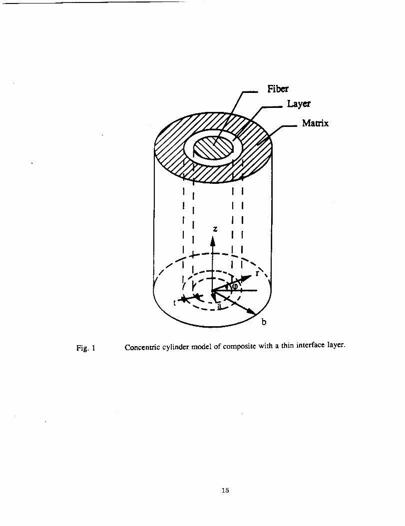
behavior of the composite may then be assumed to be given by a concentric cylinder model,
Fig. 1. The composite is not subjected to transverse loading and the outer surface of the
compound cylinder is traction free. The fibers are long and the stress and strain distributions
are constant in the z-direction except at the end regions which are not studied here.
Ceramic fibers are usually four to five times stiffer than metal matrix materials. Hence it is
assumed, in order to simplify the calculations, that
Ef
E---- >> 1m
(1)
and
Ef
_//>> 1(2)
where the subscript f denotes fiber, m matrix, and I interface layer. The fiber volume
fraction, cf, is assumed to be of the same order as the matrix volume fraction so that

(3)
The radii defining the cylinder model (Fig.l) are related to the fiber volume fraction by the
relation
[a/b] 2 = cf (4)
The cylinder is assumed to be stress free at a given temperature T 1
subjected to a homogeneous temperature change to a lower temperature
temperature change is defined as
and is then
T 2 . The
AT = T 1 - T 2 (5)
For the given assumptions the stiff fiber controls the thermal expansion in the axial
direction of the cylinder model. Hence, the stress distribution in the matrix and interface
layer is governed by a plane strain problem with a fixed inner radius at the fiber interface.
The problem is formulated in terms of the differential CI'E's of matrix and fiber
A0cm = 0_m - o_f (6a)
and of interface layer and fiber
ACtI = ct I -- czf (6b)
The stress distribution in the matrix is given by the plane strain solution for a thick
walled cylinder subjected to an unknown internal pressttre p, a traction free outer surface,

and a temperaturechange AT. Superimposing the solutions given in [5] for an internal
pressure and a temperature change gives the stress distributions in the matrix
o =-P [b/r] 2- 1 (7a)
rm [b/a] 2- 1
[b/r]2+ 1
°q)m = P [b/a]2- 1(7b)
UZITI
=p
2 vm
[b/a] 2_+ EmAamAT
1(7c)
The hoop strain is
1 -v 2 v
m [[b/r]2+ 1 + m {[b/r]2_ 1 }]etPm= re[b/a]2- 1 1 - v m
- [1 + Vm]ACtmAT (8)
The interface layer is assumed to be sufficiently thin for the variation of stress in the
radial direction to be neglected. Because of the rigidity of the fiber the deformation of the
layer is suppressed in the hoop and axial direction by the fiber so that
egl = 8zl = 0 (9a,b)
The layer is subjected to a pressure in the radial direction resulting from the contact with
the matrix
4

Orl = -p (lOa)
The temperature change AT introduces stresses in the hoop and longitudinal directions due
to the constraint from the fibers (9). The stresses in the hoop and longitudinal direction are
equal and are the sum of the stresses caused by the pressure and the thermal expansion
Vl 1
%,= -r- l p+ Eta' t (10b,c)
The stresses in the layer give rise to the radial strain
er/=_[l_ 2[ v 2] 1 + v I (11)
Compatibility in the radial displacement at the boundary between the inner surface
of the matrix and the interface layer at r = a, requires
ecpm a = er lt (12)
The pressure in the radial direction at the layer is now derived by substituting (4)
and (8) in (12) and using (11) to give
t A0t l i +Vl
[1 + Vm] - _ 1 - v l
P = 1 + cf v m t E Vl EmA0tmAT (13)
2[ ] + m[1 - v ] T--cf + 1 -- v m a-E-T-/ -[ -v l

STRESSES IN MATRIX
The highest stresses in the matrix occur at the inner surface of the cylinder, r = a.
The principal stresses are given by (7a-c) by letting r = a and using (4). The v. Mises
effective stress
2 + o_z _ OrOq_ _ OrOz _ otpoz (14)
can be calculated from the principal stresses given in (7) as
ge =[/p cf 12 2 cfm _l---2--_fj [3/cf + 1 --4Vm(1 - Vm) ] - p EmA0cmaT -I--=--cf2tl - 2Vml+
[EmAamAT]2 ] 1/2 (15)
The stresses in the matrix are readily found by first calculating the interface layer
pressure for a given temperature change AT using (13) and using this value in (7a-c) and
(15) to determine the stresses. The term EmACtmAT enters in all the expressions for stress
and all results can be normalized with respect to this term. The stresses at the inner radius
of the matrix are shown in Fig. 2 as a function of normalized pressure for a fiber volume
fraction cf = 0.4 in a Ti3A1 matrix for which v m = 0.25. It can be seen that pressure at
the interface causes increased tensile stresses in the hoop and axial direction which could
result in matrix cracking, which is initiated from defects at the fiber matrix interface. The
effective stress is a minimum when the interface pressure that is close to zero. Consequently
the pressure should be low in order to have good low cycle fatigue properties of the
composite.
6
For anygiven compositea plot similar to Fig. 2 can beproduced.The value of the
critical stressfor matrix cracking, acre, setsan upperlimit for the principal stressesa_pm
' gzm ' and t_rm and defines bounds on the pressure p if matrix failure is to be avoided.
The allowable effective stress, _ym ' in the matrix defines other bounds on the pressure.
These bounds define a window for the interface pressure (Fig 2.) if the failure criteria are
not to be violated. If the calculated pressure does not fall within the allowable window it
must be adjusted to avoid matrix cracking or failure due to high effective stress.
Inspection of (13) reveals that the pressure may be reduced in two ways by the
introduction of interface layers. A compliant layer with low modulus would increase the
denominator in (13) while a comt_nsating layer with a high coefficient of thermal
expansion would decrease the numerator in (13). An appreciation for the potential of the
two effects can be obtained by evaluating the requirements to reduce the pressure by a
factor two. To achieve this condition using a compliant layer means that the two terms in
the denominator of (13) are equal and gives the result,
El t
=_(I - vl)(1
vl(l - cf)+ Vm)[(1- Vm)(1 + cf) + Vm(1 -cf)] (16)
For the present composite, using vI = 0.3, this requires that
El tE-- = 0.17 _-
m
In general the layer has to be thin in order to keep the density down of the composite, and a
realistic value of t/a is 0.1 . This requires that the modulus of the layer must be
unrealistically low for the pressure to be reduced by a factor two. Hence it is deduced that a
compliant layer is not an efficient way to reduce thermal stresses in the matrix.

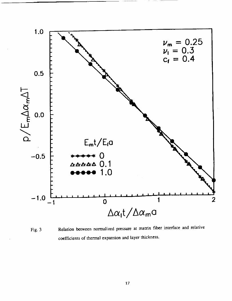
Furthermore,the secondterm in the denominator of (13) is usually sufficiently small to be
neglected in the calculations and the pressure is then linearly dependent on the normalized
thermal expansion of the layer, Aa/t/Aama. This is demonstrated in Fig. 3 where it can be
seen that the influence of Emt/E/a is small.
A reduction of the pressure by a factor two with a compensating layer requires that the
second term in the numerator of (13) is equal to half of the first term, to give,
Aal a 1 - v l 1 + v mw
t'I +Vl 2(17)
For the present composite this gives the condition
Aa l= 0.34 at
m
Hence when t/a = 0.1 the differential CTE for the layer is Aa l = 3.4 Aa m . For the case of
SiC fibers (af -- 5 10 ---6 l/C) in a Ti3AI matrix (a m --- 10 10 -'6) requires that a I _- 20 10 --6
if the pressure is to be reduced by a factor two. Handbook values [6] of metals with a
reasonably high melting point and high CTE are: silver 25 10 --6, copper 17 10 --6, and
manganese 22 10 --6 . It is evident therefore that an interface layer of readily available
materials with high CTE has the potential to substantially reduce thermal stresses in the
matrix.
The results given in Fig. 2 and Fig. 3 have been combined in Fig. 4 where the
highest principal stress and effective stress at the inner radius of the matrix cylinder are
plotted against the normalized thermal expansion of the layer. No interface layer
corresponds to Aalt/AOtma = 0. It can be deduced that a layer with a lower CTE than the

matrix will increasethestressesin thematrix and a layer with a higher CTE than the matrix
reduces the stresses in the matrix. The effective and principal stress have minima for
different layer characteristics and the required thermal expansion of the layer, ACXlt, has to
be a compromise as discussed earlier. The highest effective stress in the matrix, (15),
governs the low cycle fatigue performance of the composite when it is subjected to thermal
cycling. Shake down to linear elastic stress strain response is expected when the cyclic
effective stress, based on a linear elastic calculation, is less than twice the yield stress. The
shake down condition is plotted in Fig. 5 as a function of the normalized thermal expansion
of the layer. It can be seen that an interface layer can double the allowable temperature
range for elastic shake down in the matrix.
STRESSES IN INTERFACE LAYER
The tradeoff for the improved stress state in the matrix is that the thermal mismatch
has to be taken up by the interface layer. The deformation of the layer is constrained in the
hoop and longitudinal direction so that tensile stresses develop in these directions. The
highest principal stress in the interface layer which is given by substituting (13) in (10b), is
shown in Fig. 6 as a function of the dimensionless parameters defining the problem. The
stress is strongly dependent on the layer modulus, E//E m , and CTE , Aa//Aa m , but
weakly dependent on the layer thickness t/a. This indicates that the stress is dominated by
the constrained thermal expansion [ given by the second term in (10b)] and is weakly
dependent on the interface pressure [ given by the first term in (10b)]. The product Aalt
governs the reduction of stress in the matrix (Fig. 4) and must have a required value to
reduce the stresses in the matrix to an acceptable level. It can be deduced from Fig. 4 and
Fig. 6 that it is more favorable to have a thick layer and a moderate high layer CTE than a
thin layer and a high layer CTE, to meet the requirements of stress reduction in the matrix
and avoidance of high tensile stresses in the layer.

The effectivestressin the layer is given by inserting (10a-c) in (14) to give
¢_le= -Y_/1 I EIAtX/AT + (1 - 2v/) pl (18)
Shake down to elastic response in the layer is expected when the cyclic part of the
effective stress is less than twice the yield stress of the layer. The shake down limit has
been plotted in a normalized form in Fig. 7 for different layer modulus and thickness. The
stress in the layer is strongly dependent on the layer modulus and to ensure shake down it is
desirable to have a layer with a high yield stress and a low modulus.
THE EFFECT OF YIELDING OF THE INTERFACE LAYER
The previous calculations indicate that the layer can be subjected to high stresses
and may yield. An estimation of how yielding in the layer affects reduction of the stresses
in the matrix can be obtained by examining the behavior of an elastic-perfectly plastic
layer. In the analyses the layer is assumed to be in an initial elastic stress state which
satisfies the yield condition (14). The cylinder is subsequently subjected to a further
temperature change dT so that the radial pressure changes by dp . The loading is such
that the layer remains yielded during the subsequent deformation requiring the effective
stress to be constant. Differentiation of (14) and using the condition at yield, (10b,c), gives
an incremental stress change in the layer which is hydrostatic. Thus, the stress increments
are
dt_zl = datp I = dCrl =-dp (19a,b,c)
10

Sincethe total strainsof the layer in the q_ and z directions are constrained to be zero,
(9a,b), it follows that the plastic strains in these directions are the sum of the elastic and
thermal part
1 - 2v 1
d_l = d_P l = - Aot/dT + E1 dp(20a,b)
The plastic deformation is incompressible requiring
(21)
and the total strain increment in the radial direction is the sum of the elastic, thermal, and
plastic component and becomes
deP1 1 -2Vl 1 -2vlrl = E l dp + Ao_/dT + dePzl = 3Ao_/dT- 3 El dp (22)
The radial strain in the layer governs stress reduction in the matrix and an appreciation for
the effect of the yielded layer can be determined by comparing the radial strain for an
elastic layer, Eq. (11), with the radial strain for an elasto-plastic layer, Eq. (22). The
contribution from the pressure p in both these equations is small and can be neglected.
The strains are then only linearly dependent on the temperature change. By letting AT =
-dT in Eq. (1 I) the ratio of the two strains is found to be
Pl 3(1dSrl
de req/ 1
- Vl)
+ v l(22)
11
To estimatethe effect of the elasto-plastic deformation, the second term in the numerator
of (13) must be multiplied by the right hand side of (22) when calculating the pressure. For
the present data , with v l = 0.3 , this implies that the thermal expansion of the layer
becomes 1.5 times more effective in reducing the pressure. Hence the results of the elastic
solutions given in Fig. 3-5 can be readily modified to include plastic deformation in the
layer.
CONCLUSIONS
A compliant layer must to be unrealistically flexible to reduce thermal stresses in the
matrix.
A compensating layer with a high coefficient of thermal expansion (not
unrealistically high) has the potential of reducing the thermal stresses in the matrix
significantly.
The hoop stress in the matrix close to the fiber can be reduced substantially but the
axial stress in the matrix is less affected by a layer. This implies that compensating layers
can be expected to be successful in preventing cracking in composites where predominantly
radial cracking is observed in the matrix.
The shake down range to linear elastic response in the matrix can be extended
significantly with the addition of a compensating layer.
The thermal mismatch between fiber and matrix is taken up by the layer which can
cause high stresses in the layer. The required stress reduction in the matrix sets a
requirement on the value of the thermal expansion of the layer, ACtlt. However, the stress
12
in the layer is proportional to Aa I so that a high layer CTE can cause high stress in the
layer. In order to have low stress in the layer it is more favorable to have a moderately high
layer CTE and thick layer than a thin layer with very high layer CTE. A low elastic
modulus of the layer reduces the stresses in the layer. The effect of plastic deformation of
the layer on the stress reduction in the matrix is equivalent to increasing the CTE of the
layer by 1.5.
Thermal stresses build up in the layer because the required thermal expansion in the
radial direction is different from the thermal expansions in the hoop and longitudinal
directions that are governed by the fiber. The stresses in the layer could be minimized if a
layer could be developed with an anisotropie thermal expansion such that the thermal
expansion is close to the fiber CTE in the longitudinal and hoop directions and high in the
radial direction.
Residual stresses can be reduced by Compensating layers for other reinforcements
shapes than fibers. Thermal expansion of reinforcements with lower aspect ratios is less
anisotropic and can be better compensated for by a layer with an isotropic CTE. The thermal
mismatch for a spherical inclusion can be compensated for fully and no residual stresses would
develop in the matrix.
ACKNOWLEDGEMENT
The work was supported by a grant from the NASA Lewis Research Center. The
authors wish to express their gratitude to Dr. Steve Arnold for the encouragement and
support.
13

REFERENCES
[1] Castelli, M. G. et. al., "Development of Thermomechanical Testing Techniques for
Advanced Composites," 2nd HITEMP Review, NASA CP-10039, paper 43, 1989.
[2] Brindley, P. K., Bartolotta, P. A. and MacKay, R. A., "Thermal and Mechanical
Fatigue of SiC/Ti3AI+Nb," 2nd HITEMP Review, NASA CP-10039, paper 52,
1989.
[3] Ohosn, L. J. and Bradley, A. L. "Optimum Interface Properties for Metal Matrix
Composites," NASA TM-102295. 1989
[4] Caruso, J. J., Chamis, C. C. and Brown, H. C., "Parametric Studies to Determine the
Effects of Compliant Layers on Metal Matrix Composite Systems," NASA
TM-102465, 1990.
[5] Timoshenko, S. P. and Goodier, J. N., "Theory of Elasticity," McGraw-Hill,
Auckland, 1970.
[6] Boyer, h. E. and Gall, T. L., "Metals Handbook, Desk Edition,", ASM, Metals Park,
1985.
14
Fiber
Matrix
I II z
i i II
.,-_, LAP-.,
Fig. 1 Concentric cylinder model of composite with a thin interface layer.
15

4
[ Vm = 0.25I e cf 0.4
3
2
<3E
Lt3o
b
AIIowoblePressure
-0.5 0.0 0.5 1.0
plE A AT
Fig. 2 Stresses at the inner surface of the matrix cylinder as a function of
normalized pressure at the matrix fiber interface.
16
1.0
0.5
<3 0.0E
!,1
Q_
-1
Emt/Eio
Fig. 3 Relation between normalized pressure at matrix fiber interface and relative
coefficients of thermal expansion and layer thickness.
17

<3E
Lt_l
b
2.5
2.0
1.5
1.0
0.5
m
m
\
\
\
\ 0 "e
\
\
\
\
\
\
\
\
\
\
I
I
I
I
/
I
/
I
/
/
I
I
I
I
I
/
i i I l m l I I i i I m i i i i I I l l i i m i i I i i i
-0 I
Ac ,t/Ac ,.o
2
Fig. 4 Maximum principal stress and effective stress at the inner surface of the
matrix cylinder as a function of the relative thermal expansion of the layer.
18

,i
2.5
Optimol Loyer
b
k-<3
<3E
I,I
2.0
1.5
1.0
0.5
No Loyer
Shoke DownRegion for Motrix
A ,t/Acx o
Fig. 5 Condition for elastic shake down in the matrix.
19

10
8
I--<3
6<3
4i
N
2
01
b
2
1.0
.,,,..,
I. El/Era = 0.5
3 4 5 6 7 8
AO_I/AO_m
t/o
9 10
Fig. 6 Longitudinal and hoop tensile stress in interface layer.
20
i
N.,,oo.,Ao,oo.o,,c..o0 Report Documentation PageSpace Adm_nfstrallon
1. Report No. 2. Government Accession No. 3. Recipient's Catalog No,
NASA CR- 185302
4, Title and Subtitle
Reduction of Thermal Stresses in Continuous Fiber Reinforced
Metal Matrix Composites With Interface Layers
7. Author(s)
S. Jansson and F.A. Leckie
9. Performing Organization Name and Address
University of California
Santa Barbara, California 93106
12. Sponsoring Agency Name and Address
National Aeronautics and Space AdministrationLewis Research Center
Cleveland, Ohio 44135-3191
5. Report Date
October 1990
6. Performing Organization Code
8. Performing Organization Report No.
None
10. Work Unit No.
510-01-01
11. Contract or Grant No.
NAG3-894
13. Type of Report and Period Covered
Contractor ReportFinal
14. Sponsoring Agency Code
15. Supplementary Notes
Project Manager, Stevcn M. Arnold, Structures Division, NASA Lewis Research Center.
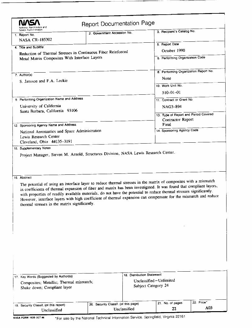
16. Abstract
The potential of using an interface layer to reduce thermal stresses in the matrix of composites with a mismatch
in coefficients of thermal expansion of fiber and matrix has been investigated. It was found that compliant layers,
with properties of readily available materials, do not have the potential to reduce thermal stresses significantly.
However, interface layers with high coefficient of thermal expansion can compensate for the mismatch and reduce
thermal stresses in the matrix significantly.
17. Key Words (Suggested by Author(s))
Composites; Metallic; Thermal mismatch;
Shake down; Compliant layer I19 Security Classif. (of this report) [ 20. Security Classif. (of this page) 1 21. No. of pages
Unclassified Unclassified 22/ |
Distribution Statement
Unclassified- Unlimited
Subject Category 24
22. Price*
A03
NASAFORM1626OCT86 *For sale by the National Technical Information Service, Springfield, Virginia 22161

2.5
[. v_ = 0.25v, = 0.3
II, = 0.4Cf2.0
I 2 3 4 5
t//o
0.010.1
0.2
6 7 8 9 10
AO(I/A(Xm
Fig. 7 Condition for elastic shake down in the interface layer. Shake down occurs
for temperature changes corresponding states under the curve defined by the
composite parameters.
21


National Aeronautics and
Space Administration
Lewis Research CenterCleveland. Ohio 44135
olJeml _
FOURTH CLASS MAIL
ADDRESS CORRECTION REQUESTED
IIIIII
Postage _ Fees PaidNational Aeronautics and
Space Administration
NASA-451


![Repair of bridges using Fiber Reinforcement Polymers (FRP) ria.pdf · PDF fileTable 7: Rebar Stresses from Static Tests (MPa) [46] ... Fiber reinforced polymer composites (FRP), developed](https://img.pdfslide.us/doc/110x75/5ab34df47f8b9ac66c8e30d4/repair-of-bridges-using-fiber-reinforcement-polymers-frp-7-rebar-stresses-from.jpg)