Embed Size (px)
Citation preview
UNCLASSIFIED
Executive summary
UNCLASSIFIED
Nationaal Lucht- en Ruimtevaartlaboratorium
National Aerospace Laboratory NLR
This report is based on a presentation held at the 16th AIAA/CEAS Aeroacoustics Conference, Stockholm, 7-9 June 2010.
Report no. NLR-TP-2010-405 Author(s) S. Oerlemans C. Sandu N. Molin J.F. Piet Report classification UNCLASSIFIED Date December 2010 Knowledge area(s) Aëro-akoestisch en experimenteel aërodynamisch onderzoek Descriptor(s) landing gear airframe noise
Reduction of Landing Gear Noise using Meshes
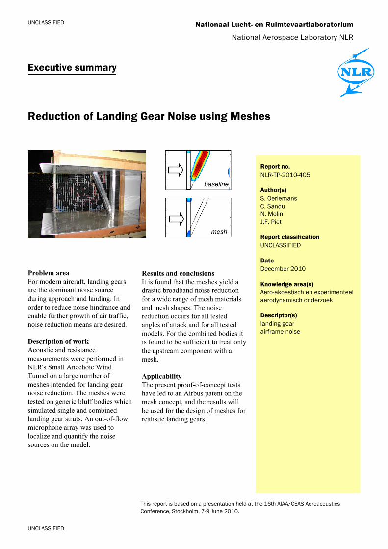
Problem area For modern aircraft, landing gears are the dominant noise source during approach and landing. In order to reduce noise hindrance and enable further growth of air traffic, noise reduction means are desired. Description of work Acoustic and resistance measurements were performed in NLR's Small Anechoic Wind Tunnel on a large number of meshes intended for landing gear noise reduction. The meshes were tested on generic bluff bodies which simulated single and combined landing gear struts. An out-of-flow microphone array was used to localize and quantify the noise sources on the model.
Results and conclusions It is found that the meshes yield a drastic broadband noise reduction for a wide range of mesh materials and mesh shapes. The noise reduction occurs for all tested angles of attack and for all tested models. For the combined bodies it is found to be sufficient to treat only the upstream component with a mesh. Applicability The present proof-of-concept tests have led to an Airbus patent on the mesh concept, and the results will be used for the design of meshes for realistic landing gears.
baseline
mesh

UNCLASSIFIED
UNCLASSIFIED
Reduction of Landing Gear Noise using Meshes
Nationaal Lucht- en Ruimtevaartlaboratorium, National Aerospace Laboratory NLR Anthony Fokkerweg 2, 1059 CM Amsterdam, P.O. Box 90502, 1006 BM Amsterdam, The Netherlands Telephone +31 20 511 31 13, Fax +31 20 511 32 10, Web site: www.nlr.nl
Nationaal Lucht- en Ruimtevaartlaboratorium
National Aerospace Laboratory NLR
NLR-TP-2010-405
Reduction of Landing Gear Noise using Meshes
S. Oerlemans, C. Sandu1, N. Molin2 and J.F. Piet2
1 SMCPFA-Turbomecanica SA 2 Airbus Operations SAS
This report is based on a presentation held at the 16th AIAA/CEAS Aeroacoustics Conference, Stockholm,
7-9 June 2010.
The contents of this report may be cited on condition that full credit is given to NLR and the authors.
This publication has been refereed by the Advisory Committee AEROSPACE VEHICLES.
Customer European Commission
Contract number ----
Owner NLR
Division NLR Aerospace Vehicles
Distribution Unlimited
Classification of title Unclassified
December 2010 Approved by:
Author
Reviewer Managing department
NLR-TP-2010-405
2
Contents
I. Introduction 3
II. Test Set-up 3
III. Results and discussions 6
IV. Conclusion 16
Acknowledgement 16
References 16
NLR-TP-2010-405
3
American Institute of Aeronautics and Astronautics
1
Reduction of Landing Gear Noise using Meshes
Stefan Oerlemans1 National Aerospace Laboratory NLR, Emmeloord, The Netherlands
Constantin Sandu2 SMCPFA-Turbomecanica SA, Bucharest, Romania
and
Nicolas Molin3 and Jean-François Piet4 Airbus Operations SAS, Toulouse, France
Acoustic and resistance measurements were performed in NLR's Small Anechoic Wind Tunnel on a large number of meshes intended for landing gear noise reduction. The meshes were tested on generic bluff bodies which simulated single and combined landing gear struts. An out-of-flow microphone array was used to localize and quantify the noise sources on the model. It is found that the meshes yield a drastic broadband noise reduction for a wide range of mesh materials and mesh shapes. The noise reduction occurs for all tested angles of attack and for all tested models. For the combined bodies it is found to be sufficient to treat only the upstream component with a mesh.
I. Introduction OR modern aircraft, landing gears are important noise sources during approach and landing. In order to reduce noise hindrance and enable further growth of air traffic, noise reduction means are desired. In the framework of
the European project TIMPAN (Technologies to IMProve Airframe Noise), acoustic and resistance measurements were performed in NLR's Small Anechoic Wind Tunnel (KAT) on several meshes which are intended for landing gear noise reduction. The meshes are similar to perforated fairings1-4, which aim to reduce the speed of the flow impinging on a strut, while avoiding the flow displacement of a closed fairing, since this may induce high flow speeds on downstream components, leading to increased noise. In addition to the noise reduction due to reduced flow speed, meshes may also reduce the noise by the creation of small-scale vortices, which affect the noise generation mechanisms. The goal of the present test campaign was to find the optimum mesh material and geometry (in terms of noise reduction), and to determine the flow resistance of the different (installed and isolated) meshes. The meshes were tested on generic bluff bodies which simulated single and combined landing gear struts. This paper describes the experimental method and discusses the acoustic and aerodynamic test results. 1,2,3,4
II. Test Set-up
A. Wind tunnel The measurements were performed in NLR's Small Anechoic Wind Tunnel KAT (Figure 1). The KAT is an
open circuit, open jet wind tunnel. The test section is surrounded by a 5 m x 5 m x 3 m room which is completely covered with 0.5-m foam wedges, yielding more than 99% absorption above 500 Hz. Two horizontal endplates (0.90 m x 0.70 m) were mounted to the upper and lower sides of the rectangular 0.38 m x 0.51 m nozzle, providing a semi-open test section for airfoil self-noise measurements. To suppress reflections, the endplates were acoustically lined with a 5.5-cm layer of sound absorbing foam covered by a 5% open perforated plate.
1 Research engineer, Aeroacoustics Group, P.O. Box 153, 8300 AD Emmeloord, The Netherlands. 2 Senior Aerospace Engineer, SMCPFA-Turbomecanica SA, Bucharest, Romania - www.SMCPFA.com. 3 Research Engineer, Acoustics and Environment Department, 316 route de Bayonne, 31060 Toulouse, France. 4 Research Engineer, Acoustics and Environment Department, 316 route de Bayonne, 31060 Toulouse, France.
F
NLR-TP-2010-405
4
American Institute of Aeronautics and Astronautics
2
model 0.4 0.3
α
nozzle
array
endplates
0.7
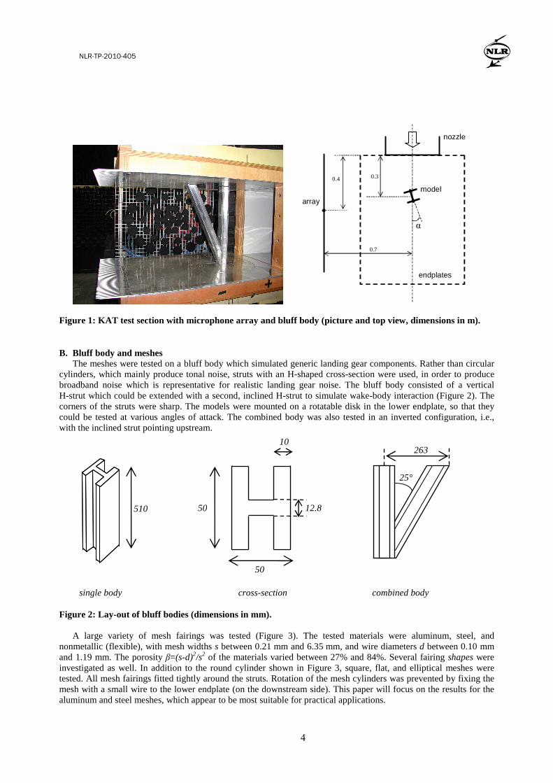
Figure 1: KAT test section with microphone array and bluff body (picture and top view, dimensions in m).
B. Bluff body and meshes The meshes were tested on a bluff body which simulated generic landing gear components. Rather than circular
cylinders, which mainly produce tonal noise, struts with an H-shaped cross-section were used, in order to produce broadband noise which is representative for realistic landing gear noise. The bluff body consisted of a vertical H-strut which could be extended with a second, inclined H-strut to simulate wake-body interaction (Figure 2). The corners of the struts were sharp. The models were mounted on a rotatable disk in the lower endplate, so that they could be tested at various angles of attack. The combined body was also tested in an inverted configuration, i.e., with the inclined strut pointing upstream.
Figure 2: Lay-out of bluff bodies (dimensions in mm).
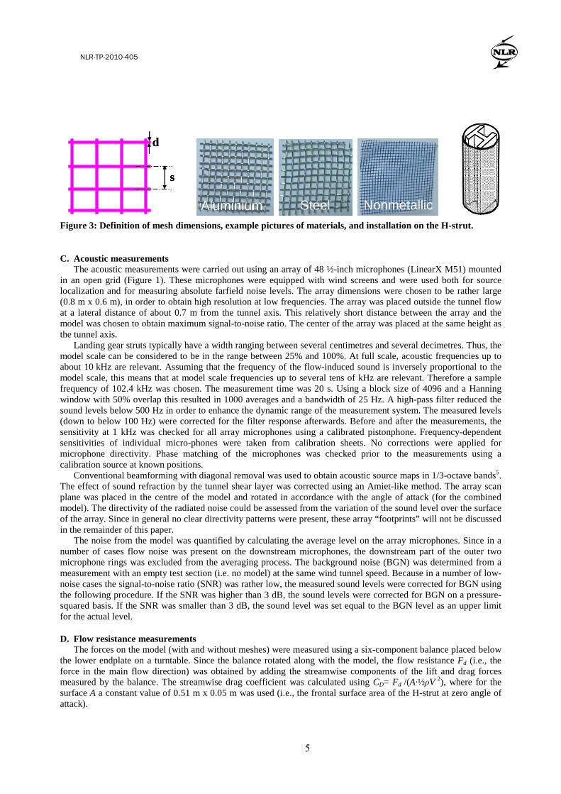
A large variety of mesh fairings was tested (Figure 3). The tested materials were aluminum, steel, and
nonmetallic (flexible), with mesh widths s between 0.21 mm and 6.35 mm, and wire diameters d between 0.10 mm and 1.19 mm. The porosity β=(s-d)2/s2 of the materials varied between 27% and 84%. Several fairing shapes were investigated as well. In addition to the round cylinder shown in Figure 3, square, flat, and elliptical meshes were tested. All mesh fairings fitted tightly around the struts. Rotation of the mesh cylinders was prevented by fixing the mesh with a small wire to the lower endplate (on the downstream side). This paper will focus on the results for the aluminum and steel meshes, which appear to be most suitable for practical applications.
50
50
10
12.8 510
25°
263
combined body cross-section single body
NLR-TP-2010-405
5
American Institute of Aeronautics and Astronautics
3
d
s
d
s
Aluminium
Steel
Nonmetallic
Figure 3: Definition of mesh dimensions, example pictures of materials, and installation on the H-strut.
C. Acoustic measurements The acoustic measurements were carried out using an array of 48 ½-inch microphones (LinearX M51) mounted
in an open grid (Figure 1). These microphones were equipped with wind screens and were used both for source localization and for measuring absolute farfield noise levels. The array dimensions were chosen to be rather large (0.8 m x 0.6 m), in order to obtain high resolution at low frequencies. The array was placed outside the tunnel flow at a lateral distance of about 0.7 m from the tunnel axis. This relatively short distance between the array and the model was chosen to obtain maximum signal-to-noise ratio. The center of the array was placed at the same height as the tunnel axis.
Landing gear struts typically have a width ranging between several centimetres and several decimetres. Thus, the model scale can be considered to be in the range between 25% and 100%. At full scale, acoustic frequencies up to about 10 kHz are relevant. Assuming that the frequency of the flow-induced sound is inversely proportional to the model scale, this means that at model scale frequencies up to several tens of kHz are relevant. Therefore a sample frequency of 102.4 kHz was chosen. The measurement time was 20 s. Using a block size of 4096 and a Hanning window with 50% overlap this resulted in 1000 averages and a bandwidth of 25 Hz. A high-pass filter reduced the sound levels below 500 Hz in order to enhance the dynamic range of the measurement system. The measured levels (down to below 100 Hz) were corrected for the filter response afterwards. Before and after the measurements, the sensitivity at 1 kHz was checked for all array microphones using a calibrated pistonphone. Frequency-dependent sensitivities of individual micro-phones were taken from calibration sheets. No corrections were applied for microphone directivity. Phase matching of the microphones was checked prior to the measurements using a calibration source at known positions.
Conventional beamforming with diagonal removal was used to obtain acoustic source maps in 1/3-octave bands5. The effect of sound refraction by the tunnel shear layer was corrected using an Amiet-like method. The array scan plane was placed in the centre of the model and rotated in accordance with the angle of attack (for the combined model). The directivity of the radiated noise could be assessed from the variation of the sound level over the surface of the array. Since in general no clear directivity patterns were present, these array “footprints” will not be discussed in the remainder of this paper.
The noise from the model was quantified by calculating the average level on the array microphones. Since in a number of cases flow noise was present on the downstream microphones, the downstream part of the outer two microphone rings was excluded from the averaging process. The background noise (BGN) was determined from a measurement with an empty test section (i.e. no model) at the same wind tunnel speed. Because in a number of low-noise cases the signal-to-noise ratio (SNR) was rather low, the measured sound levels were corrected for BGN using the following procedure. If the SNR was higher than 3 dB, the sound levels were corrected for BGN on a pressure-squared basis. If the SNR was smaller than 3 dB, the sound level was set equal to the BGN level as an upper limit for the actual level.
D. Flow resistance measurements The forces on the model (with and without meshes) were measured using a six-component balance placed below
the lower endplate on a turntable. Since the balance rotated along with the model, the flow resistance Fd (i.e., the force in the main flow direction) was obtained by adding the streamwise components of the lift and drag forces measured by the balance. The streamwise drag coefficient was calculated using CD= Fd /(A·½ρV 2), where for the surface A a constant value of 0.51 m x 0.05 m was used (i.e., the frontal surface area of the H-strut at zero angle of attack).
NLR-TP-2010-405
6
American Institute of Aeronautics and Astronautics
4
The flow resistance of the isolated mesh samples was determined in a special small wind tunnel (“TSI wind tunnel”), with a nozzle diameter of 1 cm. A small sample of mesh material was placed in the nozzle, and the pressure drop over the mesh was measured for different wind speeds.
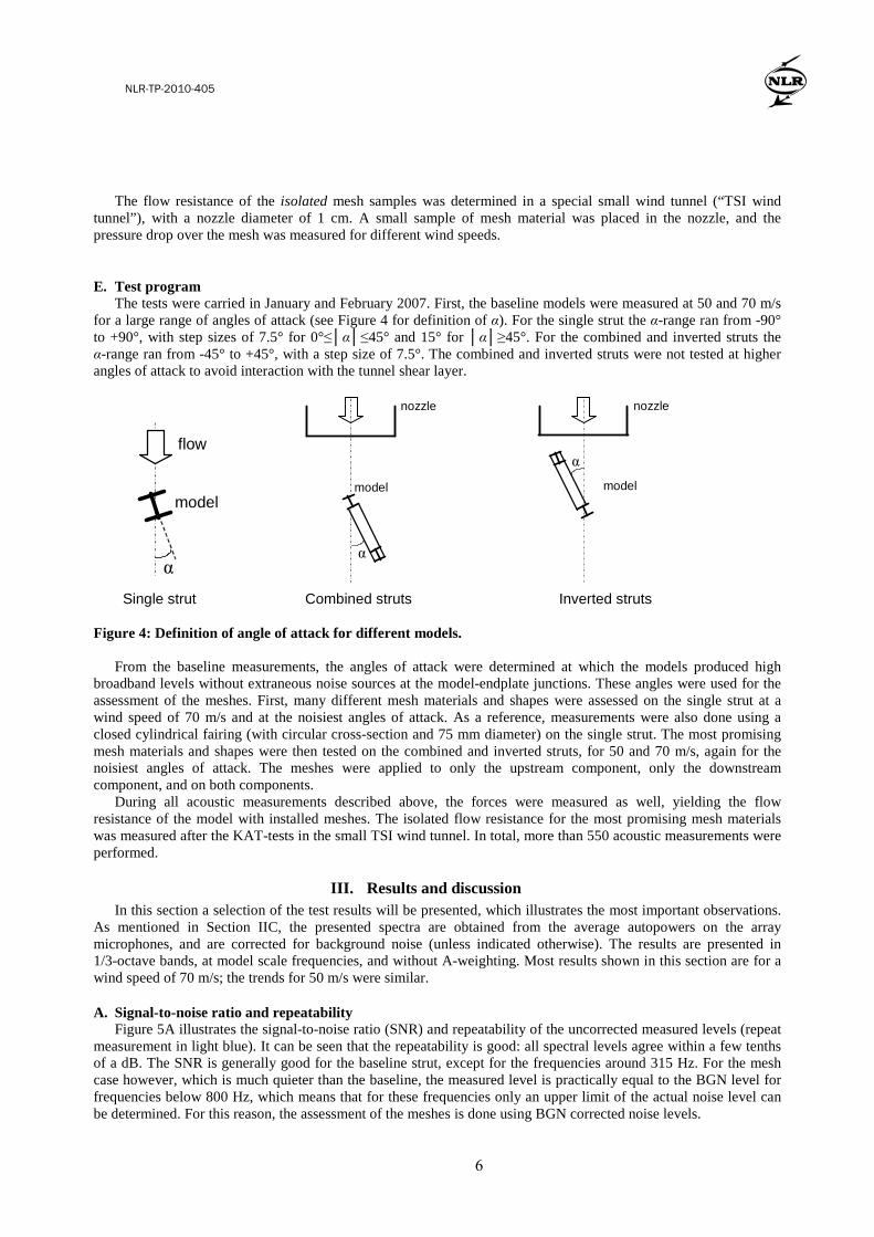
E. Test program The tests were carried in January and February 2007. First, the baseline models were measured at 50 and 70 m/s
for a large range of angles of attack (see Figure 4 for definition of α). For the single strut the α-range ran from -90° to +90°, with step sizes of 7.5° for 0°≤│α│≤45° and 15° for │α│≥45°. For the combined and inverted struts the α-range ran from -45° to +45°, with a step size of 7.5°. The combined and inverted struts were not tested at higher angles of attack to avoid interaction with the tunnel shear layer.
model
α
flow
model
nozzle
α
model
nozzle
α
Single strut Combined struts Inverted struts
Figure 4: Definition of angle of attack for different models. From the baseline measurements, the angles of attack were determined at which the models produced high
broadband levels without extraneous noise sources at the model-endplate junctions. These angles were used for the assessment of the meshes. First, many different mesh materials and shapes were assessed on the single strut at a wind speed of 70 m/s and at the noisiest angles of attack. As a reference, measurements were also done using a closed cylindrical fairing (with circular cross-section and 75 mm diameter) on the single strut. The most promising mesh materials and shapes were then tested on the combined and inverted struts, for 50 and 70 m/s, again for the noisiest angles of attack. The meshes were applied to only the upstream component, only the downstream component, and on both components.
During all acoustic measurements described above, the forces were measured as well, yielding the flow resistance of the model with installed meshes. The isolated flow resistance for the most promising mesh materials was measured after the KAT-tests in the small TSI wind tunnel. In total, more than 550 acoustic measurements were performed.
III. Results and discussion In this section a selection of the test results will be presented, which illustrates the most important observations.
As mentioned in Section IIC, the presented spectra are obtained from the average autopowers on the array microphones, and are corrected for background noise (unless indicated otherwise). The results are presented in 1/3-octave bands, at model scale frequencies, and without A-weighting. Most results shown in this section are for a wind speed of 70 m/s; the trends for 50 m/s were similar.
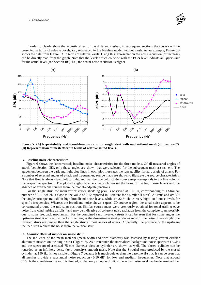
A. Signal-to-noise ratio and repeatability Figure 5A illustrates the signal-to-noise ratio (SNR) and repeatability of the uncorrected measured levels (repeat
measurement in light blue). It can be seen that the repeatability is good: all spectral levels agree within a few tenths of a dB. The SNR is generally good for the baseline strut, except for the frequencies around 315 Hz. For the mesh case however, which is much quieter than the baseline, the measured level is practically equal to the BGN level for frequencies below 800 Hz, which means that for these frequencies only an upper limit of the actual noise level can be determined. For this reason, the assessment of the meshes is done using BGN corrected noise levels.
NLR-TP-2010-405
7
American Institute of Aeronautics and Astronautics
5
In order to clearly show the acoustic effect of the different meshes, in subsequent sections the spectra will be presented in terms of relative levels, i.e., referenced to the baseline model without mesh. As an example, Figure 5B shows the data from Figure 5A in terms of relative levels. Using this representation the noise reduction (or increase) can be directly read from the graph. Note that the levels which coincide with the BGN level indicate an upper limit for the actual level (see Section IIC), i.e., the actual noise reduction is higher.
(A) (B)
Figure 5: (A) Repeatability and signal-to-noise ratio for single strut with and without mesh (70 m/s; α=0°). (B) Representation of mesh effect in terms of relative sound levels.
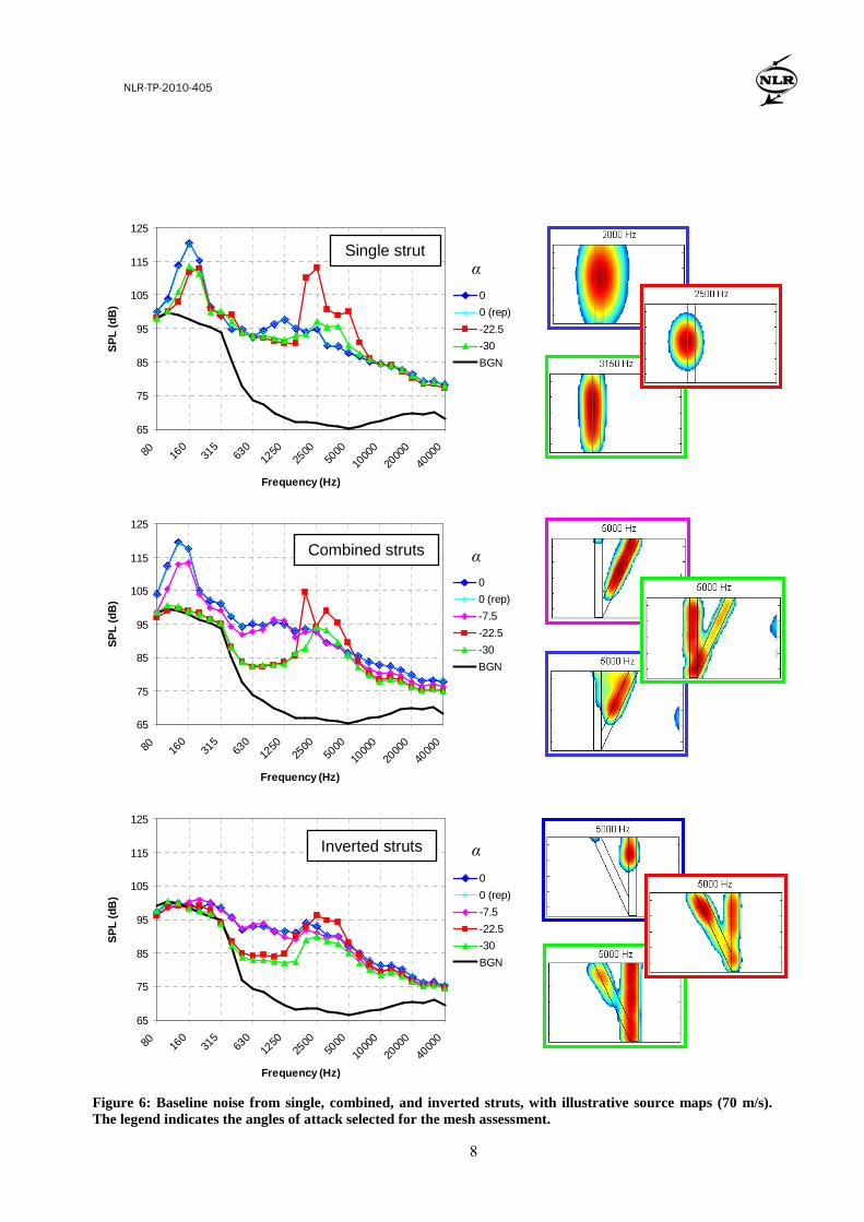
B. Baseline noise characteristics Figure 6 shows the (uncorrected) baseline noise characteristics for the three models. Of all measured angles of
attack (see Section IIE), only those angles are shown that were selected for the subsequent mesh assessment. The agreement between the dark and light blue lines in each plot illustrates the repeatability for zero angle of attack. For a number of selected angles of attack and frequencies, source maps are shown to illustrate the source characteristics. Note that flow is always from left to right, and that the line color of the source map corresponds to the line color of the respective spectrum. The plotted angles of attack were chosen on the basis of the high noise levels and the absence of extraneous sources from the model-endplate junctions.
For the single strut, the main vortex vortex shedding peak is observed at 160 Hz, corresponding to a Strouhal number of 0.11, which is close to the value of 0.12 reported in literature for a similar H-strut6. At α=0° and α=-30° the single strut spectra exhibit high broadband noise levels, while α=-22.5° shows very high tonal noise levels for specific frequencies. Whereas the broadband noise shows a quasi 2D source region, the tonal noise appears to be concentrated around the mid-span position. Similar source maps were previously obtained for tonal trailing edge noise from wind turbine airfoils,7 and may be indicative of coherent noise radiation from the complete span, possibly due to some feedback mechanism. For the combined (and inverted) struts it can be seen that for some angles the upstream strut is noisiest, while for other angles the downstream strut produces most of the noise. Interestingly, the inverted struts are quieter than the single strut at most angles of attack. Apparently, the presence of the upstream inclined strut reduces the noise from the vertical strut.
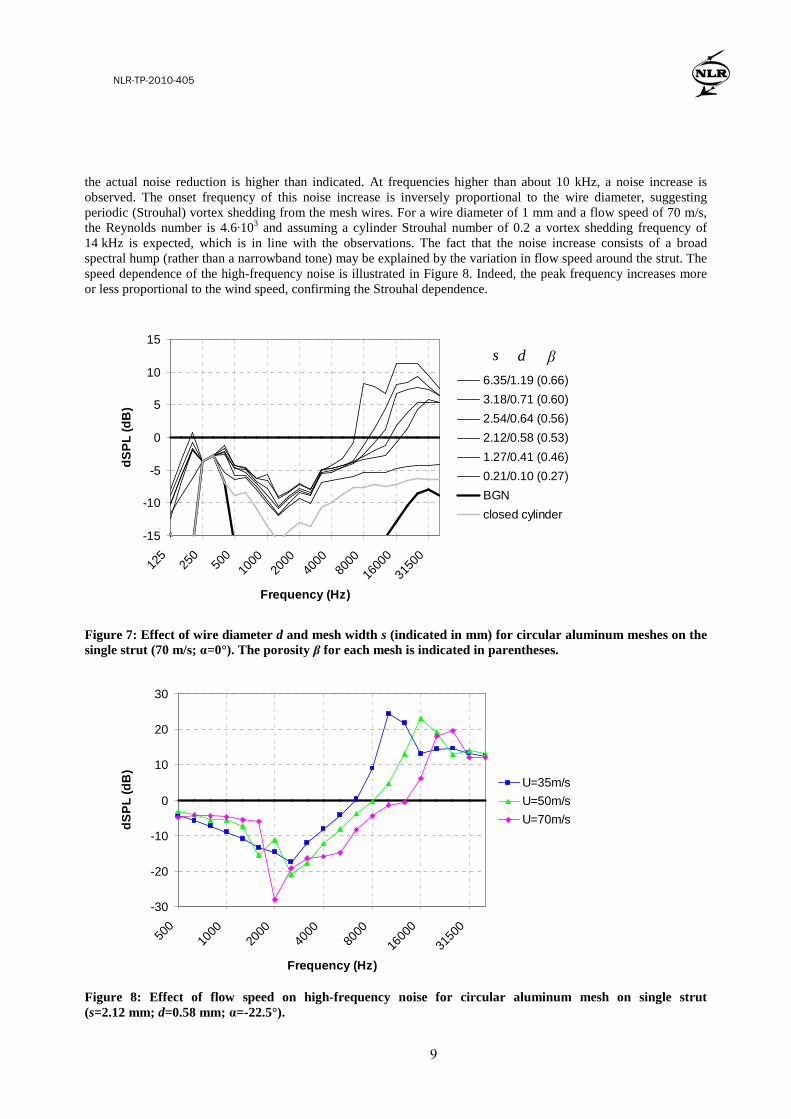
C. Acoustic effect of meshes on single strut The influence of the mesh material (mesh width and wire diameter) was assessed by testing several circular
aluminum meshes on the single strut (Figure 7). As a reference the normalized background noise spectrum (BGN) and the spectrum of a closed 75-mm diameter circular cylinder are shown as well. The closed cylinder can be regarded as an infinitely dense (zero porosity), smooth mesh. Note that the Strouhal tone produced by the closed cylinder, at 150 Hz, is not visible in Figure 7 because it is much quieter than the baseline H-strut. It can be seen that all meshes provide a substantial noise reduction (5-10 dB) for low and medium frequencies. Note that around 315 Hz the signal-to-noise ratio is limited, so that only an upper limit of the actual noise level can be determined, i.e.
65
75
85
95
105
115
125
80 160
315
630
1250
2500
5000
1000
0
2000
0
4000
0
Frequency (Hz)
SP
L (d
B)
-30
-25
-20
-15
-10
-5
0
5
10
80 160
315
630
1250
2500
5000
1000
0
2000
0
4000
0
Frequency (Hz)
dSP
L (d
B) strut
repeat
strut+mesh
BGN
NLR-TP-2010-405
8
American Institute of Aeronautics and Astronautics
6
65
75
85
95
105
115
125
80 160
315
630
1250
2500
5000
1000
0
2000
0
4000
0
Frequency (Hz)
SP
L (d
B)
0
0 (rep)
-22.5
-30
BGN
65
75
85
95
105
115
125
80 160
315
630
1250
2500
5000
1000
0
2000
0
4000
0
Frequency (Hz)
SP
L (d
B)
0
0 (rep)
-7.5
-22.5
-30
BGN
65
75
85
95
105
115
125
80 160
315
630
1250
2500
5000
1000
0
2000
0
4000
0
Frequency (Hz)
SP
L (d
B)
0
0 (rep)
-7.5
-22.5
-30
BGN
Figure 6: Baseline noise from single, combined, and inverted struts, with illustrative source maps (70 m/s). The legend indicates the angles of attack selected for the mesh assessment.
Single strut
Combined struts
Inverted struts
α
α
α
NLR-TP-2010-405
9
American Institute of Aeronautics and Astronautics
7
the actual noise reduction is higher than indicated. At frequencies higher than about 10 kHz, a noise increase is observed. The onset frequency of this noise increase is inversely proportional to the wire diameter, suggesting periodic (Strouhal) vortex shedding from the mesh wires. For a wire diameter of 1 mm and a flow speed of 70 m/s, the Reynolds number is 4.6·103 and assuming a cylinder Strouhal number of 0.2 a vortex shedding frequency of 14 kHz is expected, which is in line with the observations. The fact that the noise increase consists of a broad spectral hump (rather than a narrowband tone) may be explained by the variation in flow speed around the strut. The speed dependence of the high-frequency noise is illustrated in Figure 8. Indeed, the peak frequency increases more or less proportional to the wind speed, confirming the Strouhal dependence.
-15
-10
-5
0
5
10
15
125
250
500
1000
2000
4000
8000
1600
0
3150
0
Frequency (Hz)
dSP
L (d
B)
6.35/1.19 (0.66)
3.18/0.71 (0.60)
2.54/0.64 (0.56)
2.12/0.58 (0.53)
1.27/0.41 (0.46)
0.21/0.10 (0.27)
BGN
closed cylinder
Figure 7: Effect of wire diameter d and mesh width s (indicated in mm) for circular aluminum meshes on the single strut (70 m/s; α=0°). The porosity β for each mesh is indicated in parentheses.
-30
-20
-10
0
10
20
30
500
1000
2000
4000
8000
1600
0
3150
0
Frequency (Hz)
dSP
L (d
B)
U=35m/s
U=50m/s
U=70m/s
Figure 8: Effect of flow speed on high-frequency noise for circular aluminum mesh on single strut (s=2.12 mm; d=0.58 mm; α=-22.5°).
s d β
NLR-TP-2010-405
10
American Institute of Aeronautics and Astronautics
8
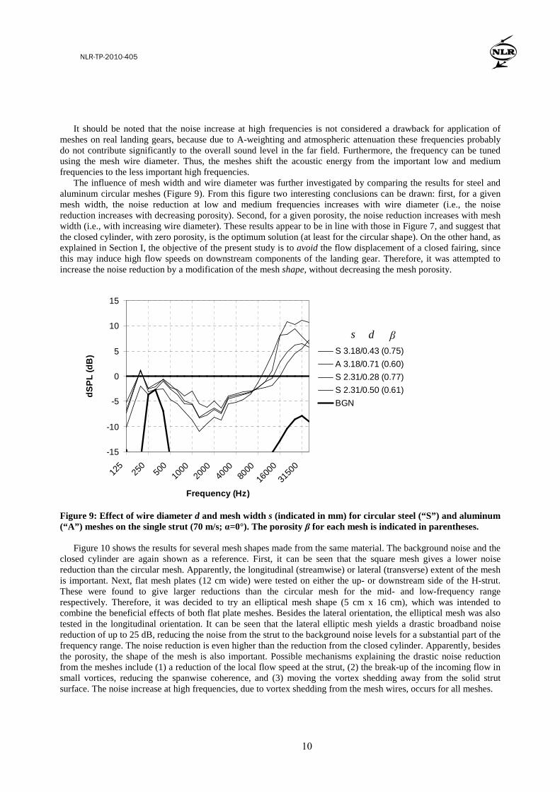
It should be noted that the noise increase at high frequencies is not considered a drawback for application of meshes on real landing gears, because due to A-weighting and atmospheric attenuation these frequencies probably do not contribute significantly to the overall sound level in the far field. Furthermore, the frequency can be tuned using the mesh wire diameter. Thus, the meshes shift the acoustic energy from the important low and medium frequencies to the less important high frequencies.
The influence of mesh width and wire diameter was further investigated by comparing the results for steel and aluminum circular meshes (Figure 9). From this figure two interesting conclusions can be drawn: first, for a given mesh width, the noise reduction at low and medium frequencies increases with wire diameter (i.e., the noise reduction increases with decreasing porosity). Second, for a given porosity, the noise reduction increases with mesh width (i.e., with increasing wire diameter). These results appear to be in line with those in Figure 7, and suggest that the closed cylinder, with zero porosity, is the optimum solution (at least for the circular shape). On the other hand, as explained in Section I, the objective of the present study is to avoid the flow displacement of a closed fairing, since this may induce high flow speeds on downstream components of the landing gear. Therefore, it was attempted to increase the noise reduction by a modification of the mesh shape, without decreasing the mesh porosity.
-15
-10
-5
0
5
10
15
125
250
500
1000
2000
4000
8000
1600
0
3150
0
Frequency (Hz)
dSP
L (d
B)
S 3.18/0.43 (0.75)
A 3.18/0.71 (0.60)
S 2.31/0.28 (0.77)
S 2.31/0.50 (0.61)
BGN
Figure 9: Effect of wire diameter d and mesh width s (indicated in mm) for circular steel (“S”) and aluminum (“A”) meshes on the single strut (70 m/s; α=0°). The porosity β for each mesh is indicated in parentheses.
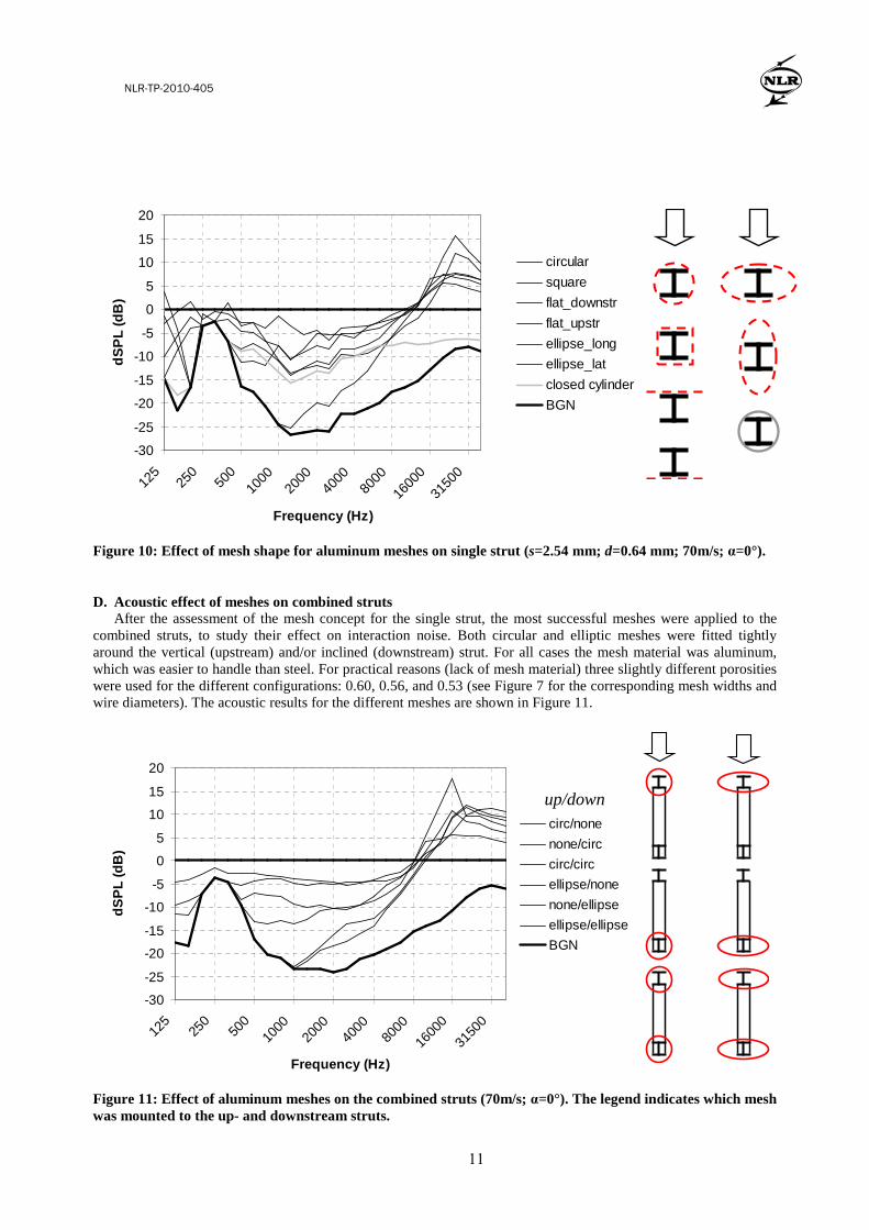
Figure 10 shows the results for several mesh shapes made from the same material. The background noise and the
closed cylinder are again shown as a reference. First, it can be seen that the square mesh gives a lower noise reduction than the circular mesh. Apparently, the longitudinal (streamwise) or lateral (transverse) extent of the mesh is important. Next, flat mesh plates (12 cm wide) were tested on either the up- or downstream side of the H-strut. These were found to give larger reductions than the circular mesh for the mid- and low-frequency range respectively. Therefore, it was decided to try an elliptical mesh shape (5 cm x 16 cm), which was intended to combine the beneficial effects of both flat plate meshes. Besides the lateral orientation, the elliptical mesh was also tested in the longitudinal orientation. It can be seen that the lateral elliptic mesh yields a drastic broadband noise reduction of up to 25 dB, reducing the noise from the strut to the background noise levels for a substantial part of the frequency range. The noise reduction is even higher than the reduction from the closed cylinder. Apparently, besides the porosity, the shape of the mesh is also important. Possible mechanisms explaining the drastic noise reduction from the meshes include (1) a reduction of the local flow speed at the strut, (2) the break-up of the incoming flow in small vortices, reducing the spanwise coherence, and (3) moving the vortex shedding away from the solid strut surface. The noise increase at high frequencies, due to vortex shedding from the mesh wires, occurs for all meshes.
s d β
NLR-TP-2010-405
11
American Institute of Aeronautics and Astronautics
9
-30
-25
-20
-15
-10
-5
0
5
10
15
20
125
250
500
1000
2000
4000
8000
1600
0
3150
0
Frequency (Hz)
dSP
L (d
B)
circular
square
flat_downstr
flat_upstr
ellipse_long
ellipse_lat
closed cylinder
BGN
Figure 10: Effect of mesh shape for aluminum meshes on single strut (s=2.54 mm; d=0.64 mm; 70m/s; α=0°).
D. Acoustic effect of meshes on combined struts After the assessment of the mesh concept for the single strut, the most successful meshes were applied to the
combined struts, to study their effect on interaction noise. Both circular and elliptic meshes were fitted tightly around the vertical (upstream) and/or inclined (downstream) strut. For all cases the mesh material was aluminum, which was easier to handle than steel. For practical reasons (lack of mesh material) three slightly different porosities were used for the different configurations: 0.60, 0.56, and 0.53 (see Figure 7 for the corresponding mesh widths and wire diameters). The acoustic results for the different meshes are shown in Figure 11.
-30
-25
-20
-15
-10
-5
0
5
10
15
20
125
250
500
1000
2000
4000
8000
1600
0
3150
0
Frequency (Hz)
dSP
L (d
B)
circ/none
none/circ
circ/circ
ellipse/none
none/ellipse
ellipse/ellipse
BGN
Figure 11: Effect of aluminum meshes on the combined struts (70m/s; α=0°). The legend indicates which mesh was mounted to the up- and downstream struts.
up/down
NLR-TP-2010-405
12
American Institute of Aeronautics and Astronautics
10
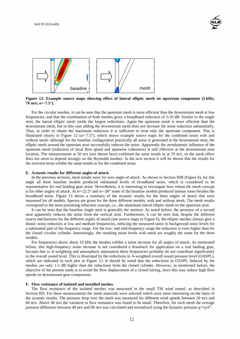
Figure 12: Example source maps showing effect of lateral elliptic mesh on upstream component (5 kHz; 70 m/s; α=-7.5°).
For the circular meshes, it can be seen that the upstream mesh is more efficient than the downstream mesh at low
frequencies, and that the combination of both meshes gives a broadband reduction of 5-10 dB. Similar to the single strut, the lateral elliptic mesh yields the largest reductions. Again the upstream mesh is more efficient than the downstream mesh, but in this case adding the downstream mesh does not increase the noise reduction substantially. Thus, in order to obtain the maximum reduction it is sufficient to treat only the upstream component. This is illustrated clearly in Figure 12 (α=-7.5°), which shows example source maps for the combined struts with and without mesh: although for the baseline configuration practically all noise is generated at the downstream strut, the elliptic mesh around the upstream strut successfully reduces the noise. Apparently the aerodynamic influence of the upstream mesh (reduction of local flow speed and spanwise coherence) is still effective at the downstream strut location. The measurements at 50 m/s (not shown here) exhibited the same trends as at 70 m/s, so the mesh effect does not seem to depend strongly on the Reynolds number. In the next section it will be shown that the results for the inverted struts exhibit the same trends as for the combined struts.
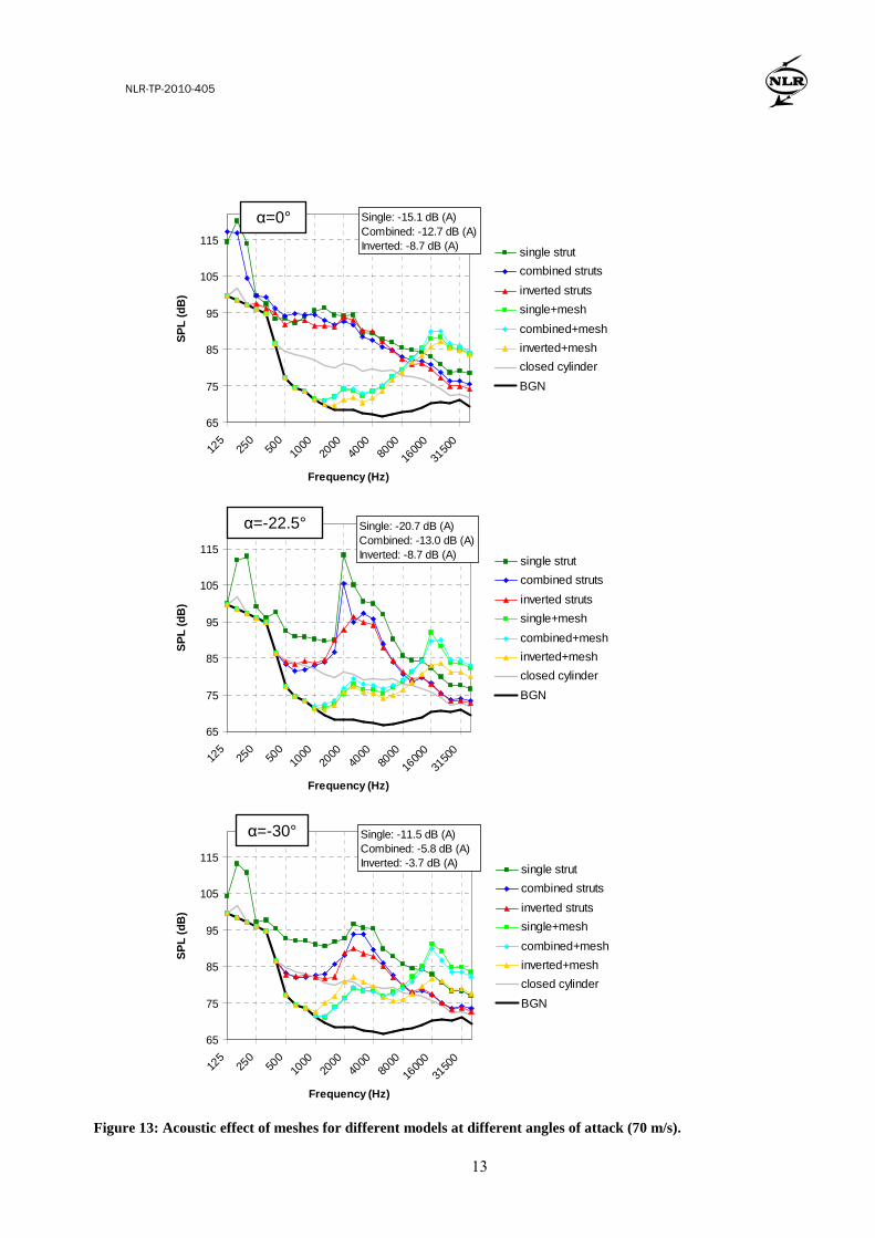
E. Acoustic results for different angles of attack In the previous sections, most results were for zero angle-of-attack. As shown in Section IIIB (Figure 6), for this
angle all three baseline models produced substantial levels of broadband noise, which is considered to be representative for real landing gear noise. Nevertheless, it is interesting to investigate how robust the mesh concept is for other angles of attack. At α=-22.5° and α=-30° some of the baseline models produced intense tones besides the broadband noise. Figure 13 shows a summary of the acoustic results for the three angles of attack that were measured for all models. Spectra are given for the three different models, with and without mesh. The mesh results correspond to the most promising reduction concept, i.e., the aluminum lateral elliptic mesh on the upstream strut.
It can be seen that the baseline single strut is generally the noisiest. As noted before, the presence of a second strut apparently reduces the noise from the vertical strut. Furthermore, it can be seen that, despite the different source mechanisms for the different angles of attack (see source maps in Figure 6), the elliptic meshes always give a drastic noise reduction at low and medium frequencies, reducing the measured noise to background noise levels for a substantial part of the frequency range. For the low- and mid-frequency range the reduction is even higher than for the closed circular cylinder. Interestingly, the resulting noise levels with mesh are roughly the same for the three models.
For frequencies above about 10 kHz the meshes exhibit a noise increase for all angles of attack. As mentioned before, this high-frequency noise increase is not considered a drawback for application on a real landing gear, because due to A-weighting and atmospheric attenuation these frequencies probably do not contribute significantly to the overall sound level. This is illustrated by the reductions in A-weighted overall sound pressure level (OASPL), which are indicated in each plot in Figure 13. It should be noted that the reductions in OASPL induced by the meshes are only 1-2 dB higher than the reductions from the closed cylinder. However, as mentioned before, the objective of the present study is to avoid the flow displacement of a closed fairing, since this may induce high flow speeds on downstream gear components.
F. Flow resistance of isolated and installed meshes The flow resistance of the isolated meshes was measured in the small TSI wind tunnel, as described in
Section IID. For these measurements the mesh materials were selected which were most interesting on the basis of the acoustic results. The pressure drop over the mesh was measured for different wind speeds between 20 m/s and 60 m/s. Above 40 m/s the variation in flow resistance was found to be small. Therefore, for each mesh the average pressure difference between 40 m/s and 60 m/s was calculated and normalized using the dynamic pressure q=½ρV2.
baseline mesh
NLR-TP-2010-405
13
American Institute of Aeronautics and Astronautics
11
65
75
85
95
105
115
125
250
500
1000
2000
4000
8000
1600
0
3150
0
Frequency (Hz)
SP
L (d
B)
single strut
combined struts
inverted struts
single+mesh
combined+mesh
inverted+mesh
closed cylinder
BGN
Single: -15.1 dB (A)Combined: -12.7 dB (A)Inverted: -8.7 dB (A)
65
75
85
95
105
115
125
250
500
1000
2000
4000
8000
1600
0
3150
0
Frequency (Hz)
SP
L (d
B)
single strut
combined struts
inverted struts
single+mesh
combined+mesh
inverted+mesh
closed cylinder
BGN
Single: -20.7 dB (A)Combined: -13.0 dB (A)Inverted: -8.7 dB (A)
65
75
85
95
105
115
125
250
500
1000
2000
4000
8000
1600
0
3150
0
Frequency (Hz)
SP
L (d
B)
single strut
combined struts
inverted struts
single+mesh
combined+mesh
inverted+mesh
closed cylinder
BGN
Single: -11.5 dB (A)Combined: -5.8 dB (A)Inverted: -3.7 dB (A)
Figure 13: Acoustic effect of meshes for different models at different angles of attack (70 m/s).
α=0°
α=-22.5°
α=-30°
NLR-TP-2010-405
14
American Institute of Aeronautics and Astronautics
12
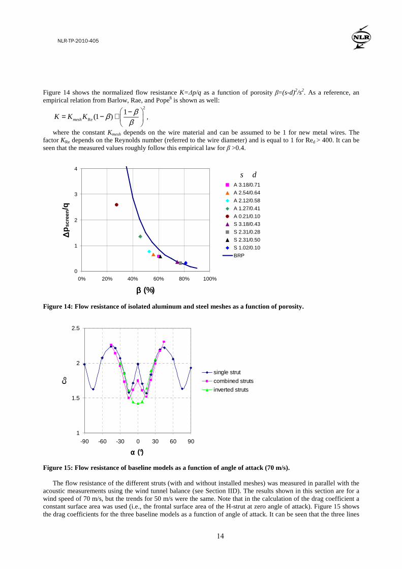
Figure 14 shows the normalized flow resistance K=∆p/q as a function of porosity β=(s-d)2/s2. As a reference, an empirical relation from Barlow, Rae, and Pope8 is shown as well:
2
Re
1(1 )meshK K K
βββ
−= − +
,
where the constant Kmesh depends on the wire material and can be assumed to be 1 for new metal wires. The factor KRe depends on the Reynolds number (referred to the wire diameter) and is equal to 1 for Red > 400. It can be seen that the measured values roughly follow this empirical law for β >0.4.
0
1
2
3
4
0% 20% 40% 60% 80% 100%
ββββ (%)
∆∆ ∆∆p
scre
en/q
A 3.18/0.71
A 2.54/0.64
A 2.12/0.58
A 1.27/0.41
A 0.21/0.10
S 3.18/0.43
S 2.31/0.28
S 2.31/0.50
S 1.02/0.10
BRP
Figure 14: Flow resistance of isolated aluminum and steel meshes as a function of porosity.
1
1.5
2
2.5
-90 -60 -30 0 30 60 90
αααα (°)
CD
single strut
combined struts
inverted struts
Figure 15: Flow resistance of baseline models as a function of angle of attack (70 m/s).
The flow resistance of the different struts (with and without installed meshes) was measured in parallel with the acoustic measurements using the wind tunnel balance (see Section IID). The results shown in this section are for a wind speed of 70 m/s, but the trends for 50 m/s were the same. Note that in the calculation of the drag coefficient a constant surface area was used (i.e., the frontal surface area of the H-strut at zero angle of attack). Figure 15 shows the drag coefficients for the three baseline models as a function of angle of attack. It can be seen that the three lines
s d
NLR-TP-2010-405
15
American Institute of Aeronautics and Astronautics
13
are quite close to each other, except around zero angle of attack. The results for the single H-strut are in good agreement with Ref. 9 (for the other models no reference data were available).
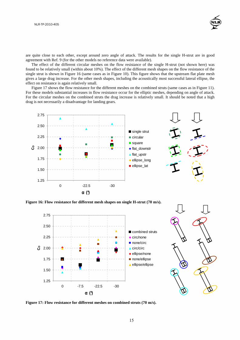
The effect of the different circular meshes on the flow resistance of the single H-strut (not shown here) was found to be relatively small (within about 10%). The effect of the different mesh shapes on the flow resistance of the single strut is shown in Figure 16 (same cases as in Figure 10). This figure shows that the upstream flat plate mesh gives a large drag increase. For the other mesh shapes, including the acoustically most successful lateral ellipse, the effect on resistance is again relatively small.
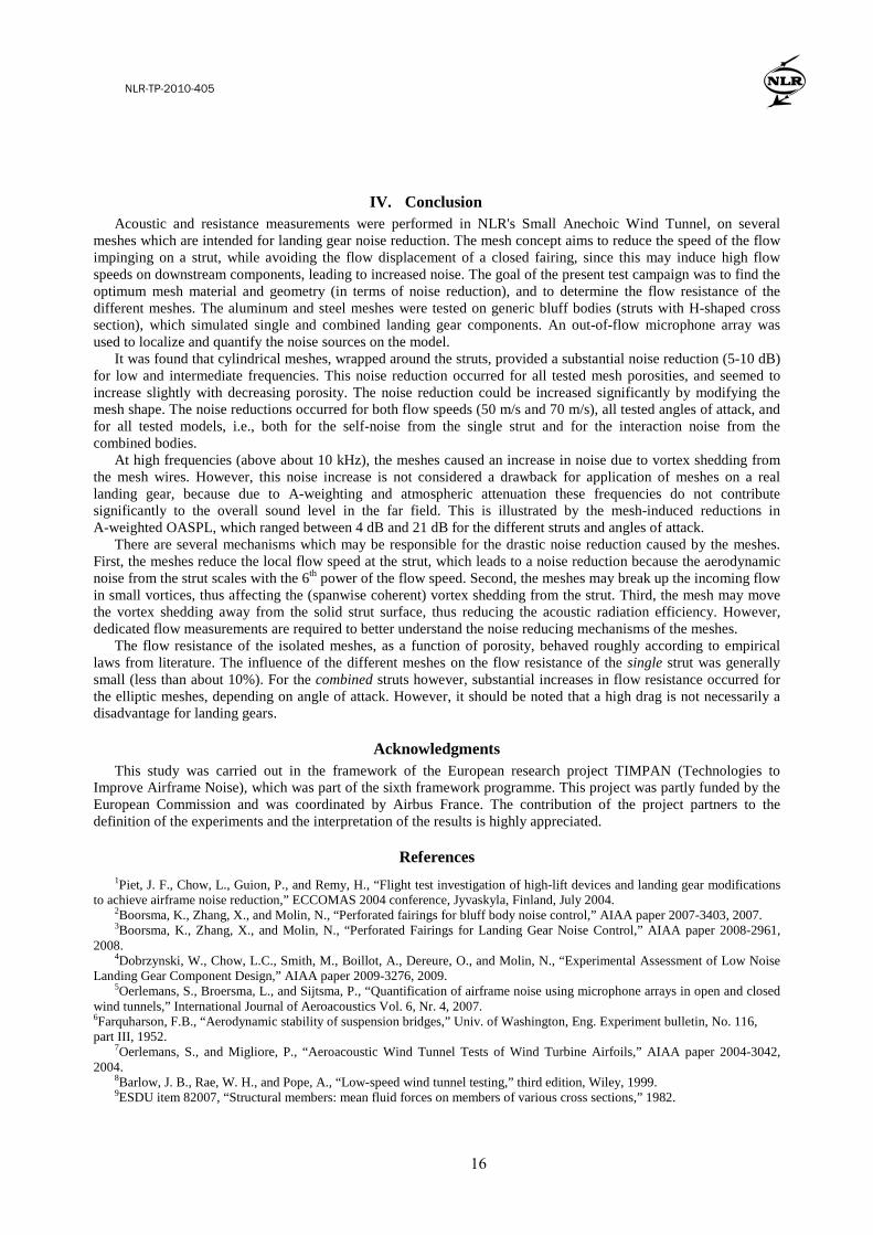
Figure 17 shows the flow resistance for the different meshes on the combined struts (same cases as in Figure 11). For these models substantial increases in flow resistance occur for the elliptic meshes, depending on angle of attack. For the circular meshes on the combined struts the drag increase is relatively small. It should be noted that a high drag is not necessarily a disadvantage for landing gears.
1.25
1.50
1.75
2.00
2.25
2.50
2.75
0 -22.5 -30
αααα (°)
CD
single strut
circular
square
flat_downstr
flat_upstr
ellipse_long
ellipse_lat
Figure 16: Flow resistance for different mesh shapes on single H-strut (70 m/s).
1.25
1.50
1.75
2.00
2.25
2.50
2.75
0 -7.5 -22.5 -30
αααα (°)
CD
combined struts
circ/none
none/circ
circ/circ
ellipse/none
none/ellipse
ellipse/ellipse
Figure 17: Flow resistance for different meshes on combined struts (70 m/s).
NLR-TP-2010-405
16
American Institute of Aeronautics and Astronautics
14
IV. Conclusion Acoustic and resistance measurements were performed in NLR's Small Anechoic Wind Tunnel, on several
meshes which are intended for landing gear noise reduction. The mesh concept aims to reduce the speed of the flow impinging on a strut, while avoiding the flow displacement of a closed fairing, since this may induce high flow speeds on downstream components, leading to increased noise. The goal of the present test campaign was to find the optimum mesh material and geometry (in terms of noise reduction), and to determine the flow resistance of the different meshes. The aluminum and steel meshes were tested on generic bluff bodies (struts with H-shaped cross section), which simulated single and combined landing gear components. An out-of-flow microphone array was used to localize and quantify the noise sources on the model.
It was found that cylindrical meshes, wrapped around the struts, provided a substantial noise reduction (5-10 dB) for low and intermediate frequencies. This noise reduction occurred for all tested mesh porosities, and seemed to increase slightly with decreasing porosity. The noise reduction could be increased significantly by modifying the mesh shape. The noise reductions occurred for both flow speeds (50 m/s and 70 m/s), all tested angles of attack, and for all tested models, i.e., both for the self-noise from the single strut and for the interaction noise from the combined bodies.
At high frequencies (above about 10 kHz), the meshes caused an increase in noise due to vortex shedding from the mesh wires. However, this noise increase is not considered a drawback for application of meshes on a real landing gear, because due to A-weighting and atmospheric attenuation these frequencies do not contribute significantly to the overall sound level in the far field. This is illustrated by the mesh-induced reductions in A-weighted OASPL, which ranged between 4 dB and 21 dB for the different struts and angles of attack.
There are several mechanisms which may be responsible for the drastic noise reduction caused by the meshes. First, the meshes reduce the local flow speed at the strut, which leads to a noise reduction because the aerodynamic noise from the strut scales with the 6th power of the flow speed. Second, the meshes may break up the incoming flow in small vortices, thus affecting the (spanwise coherent) vortex shedding from the strut. Third, the mesh may move the vortex shedding away from the solid strut surface, thus reducing the acoustic radiation efficiency. However, dedicated flow measurements are required to better understand the noise reducing mechanisms of the meshes.
The flow resistance of the isolated meshes, as a function of porosity, behaved roughly according to empirical laws from literature. The influence of the different meshes on the flow resistance of the single strut was generally small (less than about 10%). For the combined struts however, substantial increases in flow resistance occurred for the elliptic meshes, depending on angle of attack. However, it should be noted that a high drag is not necessarily a disadvantage for landing gears.
Acknowledgments This study was carried out in the framework of the European research project TIMPAN (Technologies to
Improve Airframe Noise), which was part of the sixth framework programme. This project was partly funded by the European Commission and was coordinated by Airbus France. The contribution of the project partners to the definition of the experiments and the interpretation of the results is highly appreciated.
References
1Piet, J. F., Chow, L., Guion, P., and Remy, H., “Flight test investigation of high-lift devices and landing gear modifications to achieve airframe noise reduction,” ECCOMAS 2004 conference, Jyvaskyla, Finland, July 2004.
2Boorsma, K., Zhang, X., and Molin, N., “Perforated fairings for bluff body noise control,” AIAA paper 2007-3403, 2007. 3Boorsma, K., Zhang, X., and Molin, N., “Perforated Fairings for Landing Gear Noise Control,” AIAA paper 2008-2961,
2008. 4Dobrzynski, W., Chow, L.C., Smith, M., Boillot, A., Dereure, O., and Molin, N., “Experimental Assessment of Low Noise
Landing Gear Component Design,” AIAA paper 2009-3276, 2009. 5Oerlemans, S., Broersma, L., and Sijtsma, P., “Quantification of airframe noise using microphone arrays in open and closed
wind tunnels,” International Journal of Aeroacoustics Vol. 6, Nr. 4, 2007. 6Farquharson, F.B., “Aerodynamic stability of suspension bridges,” Univ. of Washington, Eng. Experiment bulletin, No. 116, part III, 1952.
7Oerlemans, S., and Migliore, P., “Aeroacoustic Wind Tunnel Tests of Wind Turbine Airfoils,” AIAA paper 2004-3042, 2004.
8Barlow, J. B., Rae, W. H., and Pope, A., “Low-speed wind tunnel testing,” third edition, Wiley, 1999. 9ESDU item 82007, “Structural members: mean fluid forces on members of various cross sections,” 1982.