Embed Size (px)
Citation preview

ISSN 2348 – 9928 IJAICT Volume 2, Issue 5, September 2015 Doi:01.0401/ijaict.2015.05.07 Published on 05 (10) 2015
© 2015 IJAICT (www.ijaict.com)
Corresponding Author: Ms. C. Kalpa Latha, G. Pulla Reddy Engineering College, Kumool, India. 1033
REDUCTION OF COMMON-MODE VOLTAGE IN OPEN END WINDING INDUCTION MOTOR DRIVE USING CARRIER
PHASE-SHIFT STRATEGY
Ms. C. Kalpa Latha, Electrical and Electronics Engineering,
G. Pulla Reddy Engineering College, Kurnool, Andhra Pradesh, India
Abstract - Connection of two 2-level inverters at the two ends of an open end winding induction motor with equal DC-link voltages is equivalent to a conventional 3- level inverter. Better fault tolerance and flexibility in controlling is obtained in open-end winding machine configuration when compared with a conventional three-phase neutral connected electric motor. An alternating common mode voltage (CMV) is generated at the motor terminals because an output from the inverters is given to the motor is not a pure sinusoidal. This CMV result in the production of common mode current (CMC) which causes many problems in the inverter driven motor system. So in order to reduce this CMV a new technique called carrier phase shift (CPS) technique is proposed. By using this CPS strategy the CMV is reduced 50% by just shifting the carrier waves and without using any additional equipment. The proposed topology is verified in MATLAB Simulink. Keywords- Common mode voltage (CMV), Open end winding induction motor (OEWIM) drive, sinusoidal PWM, carrier phase-shift (CPS), THD, MATLAB SIMULINK.
I. INTRODUCTION
Redundant structure and high fault tolerant capability are the main objectives of recent research works in power electronics. And on other side conventional two-level three-phase voltage source inverters (VSI) are widely replaced by multilevel inverters. Therefore by combining high performance motors with multilevel inverters will have better results in industrial application. As the number of levels in the multilevel inverter increases the circuit complexity and the cost also increases. Flying capacitor inverters [1], series-connected H-bridge inverters [2], Neutral-point clamped inverters [3] and dual-inverter fed open-end winding induction motor drives [4] are the four basic topologies of multilevel inverters [5] used for large induction motor drive applications. In a series connected H-bridge topology separate DC supplies are required for each phase. Because of this, complexity of the circuit increases. The issues of a capacitor voltage unbalance
are present in 3-level NPC inverter due to the fluctuations in the neutral point voltage [6-7].Due to this unbalance in capacitor voltages, voltage stress on the switching devices increases and also lower order harmonics are produced resulting pulsation in torque. Clamping diodes or any additional capacitor banks are required in flying capacitormultilevel inverter topology [4-8]. All this drawbacks can be overcome by using dual-inverter fed open-end winding induction motor drives. Efficient operation of induction motor drive is obtained when pulse width modulated inverters are used [9].But usage of PWM inverters result in the production of high frequency and high level CMV. This CMV creates bearing currents in the motor by electrostatic coupling through parasitic capacitances [9–10].Motor leakage currents are also produced due to CMV which acts as a source for electromagnetic interference in the system [11].This undesirable current results in the failure of the motor and also speed up the aging of the motor. So, it is very important to reduce the CMV in the motor system. Anew technique called carrier phase shift (CPS) techniques is proposed in this paper to reduce the common mode voltage(CMV).
II. DUAL INVERTER FED OPEN END WINDING
INDUCTION MOTOR DRIVE The open-end winding configuration of the induction motor drive is obtained by opening the neutral point of the stator winding in a three phase induction motor. The Individual windings of each phase will be kept open and the each winding terminals a, b, c and a’, b’, c’ are fed with individual inverter. It is best suited for high-power applications. Thisopen-end winding induction motor (OEWIM) configuration has a better operation compared to all other multilevel inverter configurations [4].

ISSN 2348 – 9928 IJAICT Volume 2, Issue 5, September 2015 Doi:01.0401/ijaict.2015.05.07 Published on 05 (10) 2015
© 2015 IJAICT (www.ijaict.com)
Corresponding Author: Ms. C. Kalpa Latha, G. Pulla Reddy Engineering College, Kumool, India. 1034
Advantages of OEWIM configuration are: By using the conventional two-level inverter as its
basic block multilevel inversion is achieved. Absence of neutral point fluctuations.
Fig 1 : Dual inverter fed open end winding induction motor drive .
Reduced THD value and low dv/dt (leakage currents) at output voltages.
Fault tolerance capability Additional zero-sequence compensator circuits are
not required as zero-sequence components are not circulated, when DC links are isolated.
It has freedom to have two different single inverter’s combination.
The issues of capacitor voltage unbalance are absent
Clamping diodes or any additional capacitor banks are not required in OEWIM configuration as in flying capacitor multilevel inverter topology.
The OEWIM drive which is fed by two 2-level inverters with equal DC link voltage is shown in the Fig-1.Vao, Vboand Vco are the pole voltages of inverter-1 and Va'o, Vb'o and Vc'o are the pole voltages of inverter-2.Each two level inverter is capable of producing two pole voltages Vdc/2 and 0 independently. The effective pole voltage of the combined inverter system is obtained by the difference of the pole voltages of the two inverters which produces three voltage values resulting in the three level induction motor drive configuration which is shown in the table.1.The effective pole voltage of motor is given by
Vao ao’=Vao-Va’o’
Vao=pole voltage of inverter-1 Va’o’=pole voltage of inverter-2
Table.1.Three level operation of OEWIM drive
Pole voltage(Vao)
Pole voltage(Va’o)
Motor phase voltage
Vao ao’= Vao-Va’o
0 0 0 0 Vdc/2 -Vdc/2Vdc/2 0 Vdc/2Vdc/2 Vdc/2 0
III. COMMON MODE VOLTAGE AND CONVENTIONAL SPWM TECHNIQUE
3.1 Common mode voltage: The potential difference between ground and the neutral in an inverter is known as common mode voltage (CMV) in a two-level inverter. CMV is absent when a balanced pure sinusoidal supply is given to the system. As the output from the inverter is not pure sinusoidal CMV is generated in the OEWIM drive. In the OEWIM drive the CMV is defined as the difference of the CMV’s of the two inverters. The mathematical expression of the common mode voltage by considering the pole voltages of an inverter for a two-level inverter is given as
Vcmv = 1/3 (V ao +V bo +V co) Where Vao, Vbo, Vco are the pole voltages of Leg a, Leg b, Leg c respectively.
c’
a b Vdc/2
S1a S1b S1c
S’1a S’1b S’1c
V dc/2
S2a S2b S2c
S’2a S’2b S’2c
IM c
a’ b’
o
o’
ISSN 2348 – 9928 IJAICT Volume 2, Issue 5, September 2015 Doi:01.0401/ijaict.2015.05.07 Published on 05 (10) 2015
© 2015 IJAICT (www.ijaict.com)
The effective CMV generated for the combined inverter system is given by,
Vcmv = Vcmv –Vcmv’ Where Vcmv = (Vao+Vbo+Vco)/3, and Vcmv’ = (Va’o+Vb’o+Vc’o)/3
This CMV results in the production of leakage current called common mode current (CMC), which leads to electro-magnetic interference (EMI). Shaft voltage and bearing currents are produced when CMC is flowing through the shaft of the motor [12]–[13] which speeds up the aging of the motor bearings and also shorten the service life of motor. This CMV can be reduced by using filters but it is not economical as circuit cost increases and also circuit complexity increases. So a new technique called carrier phase shift (CPS) technique was proposed in [14]-[15] to reduce the CMV in a two level inverter. This CPS technique is used in this paper to reduce CMV in OEWIM drive circuit.
3.2 Conventional SPWM technique:
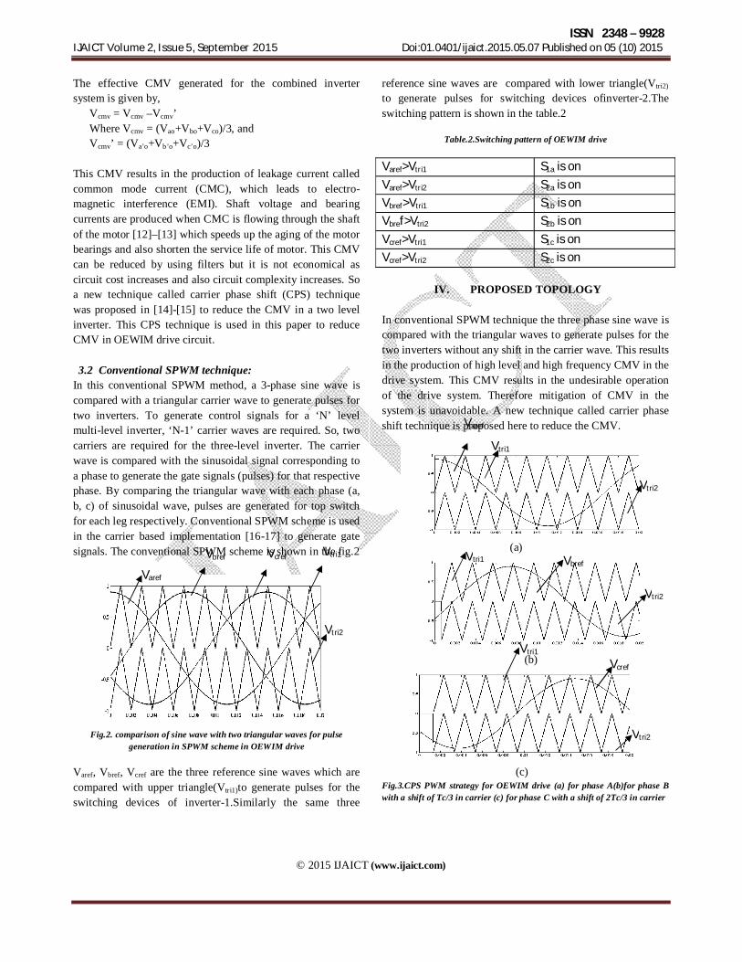
In this conventional SPWM method, a 3-phase sine wave is compared with a triangular carrier wave to generate pulses for two inverters. To generate control signals for a ‘N’ level multi-level inverter, ‘N-1’ carrier waves are required. So, two carriers are required for the three-level inverter. The carrier wave is compared with the sinusoidal signal corresponding to a phase to generate the gate signals (pulses) for that respective phase. By comparing the triangular wave with each phase (a, b, c) of sinusoidal wave, pulses are generated for top switch for each leg respectively. Conventional SPWM scheme is used in the carrier based implementation [16-17] to generate gate signals. The conventional SPWM scheme is shown in the fig.2
Fig.2. comparison of sine wave with two triangular waves for pulse
generation in SPWM scheme in OEWIM drive Varef, Vbref, Vcref are the three reference sine waves which are compared with upper triangle(Vtri1)to generate pulses for the switching devices of inverter-1.Similarly the same three
reference sine waves are compared with lower triangle(Vtri2)
to generate pulses for switching devices ofinverter-2.The switching pattern is shown in the table.2
Table.2.Switching pattern of OEWIM drive
Varef>Vtri1 S1a is on
Varef>Vtri2 S2a is on
Vbref>Vtri1 S1b is on
Vbref>Vtri2 S2b is on
Vcref>Vtri1 S1c is on
Vcref>Vtri2 S2c is on
IV. PROPOSED TOPOLOGY
In conventional SPWM technique the three phase sine wave is compared with the triangular waves to generate pulses for the two inverters without any shift in the carrier wave. This results in the production of high level and high frequency CMV in the drive system. This CMV results in the undesirable operation of the drive system. Therefore mitigation of CMV in the system is unavoidable. A new technique called carrier phase shift technique is proposed here to reduce the CMV.
(a)
(b)
(c)
Fig.3.CPS PWM strategy for OEWIM drive (a) for phase A(b)for phase B with a shift of Tc/3 in carrier (c) for phase C with a shift of 2Tc/3 in carrier
Varef
Vbref Vcref
Vtri2
Varef
Vtri1
Vtri1
Vtri2
Vbref Vtri1
Vtri2
Vtri2
Vtri1 Vcref
ISSN 2348 – 9928 IJAICT Volume 2, Issue 5, September 2015 Doi:01.0401/ijaict.2015.05.07 Published on 05 (10) 2015
© 2015 IJAICT (www.ijaict.com)
In the proposed topology the carrier triangular wave with frequency fc is compared with phase ’a’ reference wave without any shift in the carrier wave. For phase’b’ and ‘c’ the respective phases are compared with carrier wave with same frequency but with a phase shift of Tc/3 and 2Tc/3 respectively where Tc=1/ fc.By shifting the carrier wave the performance has been improved .Implementation of the proposed topology is easy and simple as it does not require any additional equipment. The CPS scheme in OEWIM drive configuration is shown in the fig.3.
The advantages of the proposed method are: Peak values of CMV are eliminated. The magnitude of CMV is reduced by 50% without
using any additional equipment
V. SIMULATION RESULTS
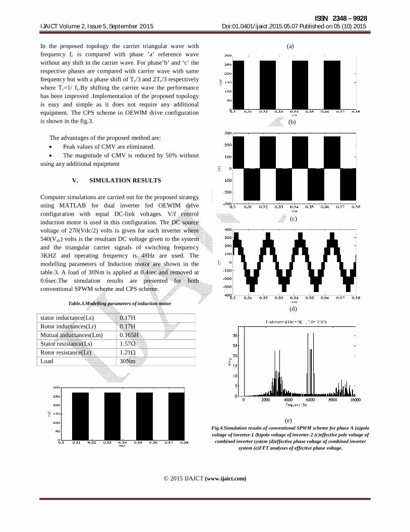
Computer simulations are carried out for the proposed strategy using MATLAB for dual inverter fed OEWIM drive configuration with equal DC-link voltages. V/f control induction motor is used in this configuration. The DC source voltage of 270(Vdc/2) volts is given for each inverter where 540(Vdc) volts is the resultant DC voltage given to the system and the triangular carrier signals of switching frequency 3KHZ and operating frequency is 48Hz are used. The modelling parameters of Induction motor are shown in the table.3. A load of 30Nm is applied at 0.4sec and removed at 0.6sec.The simulation results are presented for both conventional SPWM scheme and CPS scheme.
Table.3.Modelling parameters of induction motor stator inductance(Ls) 0.17H Rotor inductances(Lr) 0.17H Mutual inductances(Lm) 0.165H Stator resistance(Ls) 1.57 Rotor resistance(Lr) 1.21 Load 30Nm
(a)
(b)
(c)
(d)
(e)
Fig.4.Simulation results of conventional SPWM scheme for phase A (a)pole voltage of inverter-1 (b)pole voltage of inverter-2 (c)effective pole voltage of
combined inverter system (d)effective phase voltage of combined inverter system (e)FFT analyses of effective phase voltage.

ISSN 2348 – 9928 IJAICT Volume 2, Issue 5, September 2015 Doi:01.0401/ijaict.2015.05.07 Published on 05 (10) 2015
© 2015 IJAICT (www.ijaict.com)
(a)
(b)
(c)
(d)
(e)
Fig.5.Simulation results of CPS scheme for phase A (a)pole voltage of inverter-1 (b)pole voltage of inverter-2 (c)effective pole voltage of combined
inverter system (d)effective phase voltage of combined inverter system (e)FFT analyses of effective phase voltage.
The pole voltages of individual inverters, effective pole voltage, effective phase voltages and FFT analysis of the phase voltage corresponding to phase ‘A’ are shown in the figures 4 and 5 for SPWM scheme and CPS strategy respectively. Current variations are caused due to the variations in the voltages in the inverter system. This results in different THD values in proposed and conventional method. From the results it can be observed that the THD value for conventional method is 37.03% and for CPS strategy is 49.11%.The only drawback of this strategy is the THD value increases. Steady state motor currents and its FFT analyses for SPWM and CPS scheme are shown in the fig.6 and fig.7.The motor THD value are 2.33% for SPWM and for CPS scheme 4.19% .
(a)
(b)
Fig.6.(a)3-phase motor current in steady state (b) FFT analyses of motor current for SPWM strategy
(a)

ISSN 2348 – 9928 IJAICT Volume 2, Issue 5, September 2015 Doi:01.0401/ijaict.2015.05.07 Published on 05 (10) 2015
© 2015 IJAICT (www.ijaict.com)
(b)
Fig.7.(a)3-phase motor current in steady state (b) FFT analyses of motor current for CPS strategy
(a)
(b)
Fig.8.CMV for OEWIM drive (a) SPWM scheme (b) CPS scheme. The simulation results of CMV for SPWM scheme and CPS scheme are presented in the fig.8.From the simulation results the CMV magnitude of conventional SPWM is -180 to +180 volts(–Vdc /3 to Vdc /3) and with CPS scheme its magnitude is -90 to +90 volts(–Vdc /6 to Vdc /6).From this it can be observed that the magnitude of CMV is reduced by 50% by using CPS strategy. The simulation results of variation of motor current, motor torque and motor speed for different load conditions with CPS strategy are shown in fig.9.The load of 30Nm is applied at time 0.4sec and is removed at time 0.7sec.From the results it can be observed that when load is applied motor current and torque increases. This is because
when load is applied, load torque increases. According to this load torque electromagnetic torque increases by drawing more current in order to supply the required electromagnetic torque.
(a)
(b)
(c)
Fig.9 Simulation results of motor by applying the load at 0.3 and removing the load at 0.7 with CPS scheme (a)current (b)torque(c)speed
VI. CONCLUSION
In this paper advantages of dual inverter fed OEWIM drive configuration are presented. An alternating CMV is generated at the motor terminals because of the non-sinusoidal output generated at the inverter terminals. Undesirable currents are

ISSN 2348 – 9928 IJAICT Volume 2, Issue 5, September 2015 Doi:01.0401/ijaict.2015.05.07 Published on 05 (10) 2015
© 2015 IJAICT (www.ijaict.com)
Corresponding Author: Ms. C. Kalpa Latha, G. Pulla Reddy Engineering College, Kumool, India. 1039
produced in the system because of this CMV which results in the failure of motor operation and speed up the ageing of the motor. So necessity for mitigation of CMV has been increased. A new technique called CPS strategy is proposed in this paper to reduce the CMV which is produced in the system. The value of CMV is reduced by 50% and this is shown by using MATLAB simulation results. This CPS strategy is easy and simple to implement as it does not require additional equipments. The simulation results of OEWIM drive with different load conditions are also presented. Reference [1] J. S. Lai and F. Z. Peng, “Multilevel converters–A new breed of power
converters,” IEEE Trans. Ind. Applicat., vol. 32, pp. 509–517, May/June 1996.
[2] M. D. Manjrekar, P. K. Steimer, and T. A. Lipo, “Hybrid multilevel power conversion system: a competitive solution for high-power applications,”IEEE Trans. Ind. Applicat., vol. 36, pp. 834–841, May/June 2000.
[3] Jose Rodriguez, Steffen Bernet, Peter K. Steimer, Ignacio E. Lizama, “A Survey on Neutral-Point-Clamped Inverters,” IEEE Trans. Ind. Electronics, vol. 57, no. 7,pp. 2219–2230, July 2010.
[4] H.Stemmler and P.Guggenbach, “Configurations of high-power voltage source inverter drives,”. Proc. EPE Conf., vol. 5, 1993, pp.7–14.
[5] J. Rodriguez, J. S. Lai, and F. Z. Peng, “Multilevel inverters: A survey of topologies, controls, and applications,” IEEE Trans. Ind. Electron., vol. 49, no. 4, pp. 724–738, Aug. 2002.
[6] S. Ogasawara, and H. Akagi, “Analysis of variation of neutral point potential in neutral point clamped voltage source PWM inverters”, Proc. IEEE Industry Appl. Society Annual Meeting IAS, Toronto, Ontario, Canada, 1993, pp. 965-970. [
[7] N. Celanovic, and D. Boroyevich, “A comprehensive study of neutral point voltage balancing problem in three-level neutral point clamped voltage source PWM inverters”, IEEE Trans. on Power Electronics, vol. 15, no. 2, 2000, pp. 242-249.
[8] E. G. Shivakumar, K. Gopakumar, S. K. Sinha, A. Pittet, and V. T. Ranganathan, “Space vector control of dual inverter fed open end winding induction motor drive,’’ EPE J., vol. 12, no. 1, pp. 9---18, Feb. 2002.
[9] J.M.Erdman,R.J.Kerkman,D.W.Schlelgel,andG.L.Skibinski,“Effect of PWM inverters on AC motor bearing currents and shaft voltages,” IEEE Trans. Ind. Applicat., vol. 32, pp. 250–259, Mar./Apr. 1996
. [10] F. Wang, “Motor shaft voltages and bearing currents and their reduction inmultilevelmedium-voltagePWMvoltage-source-inverterdriveapplications,” IEEE Trans. Ind. Applicat., vol. 36, pp. 1336–1341, Sept./Oct. 2000.
[11] S. Chen, T. A. Lipo, and D. Fitzgerald, “Modelling of motor bearing currents in PWM inverter drives,” IEEE Trans. Ind. Applicat., vol. 32, pp. 1365–1370, Nov./Dec. 1996
[12] A.Muetze and A. Binder, “Calculation of circulating bearing currents in machines of inverter-based drive systems,” IEEE Trans. Ind.Electron. vol. 54, no. 2, pp. 932–938, Apr. 2007.
[13] F. J. T. E. Ferreira, M. V. Cistelecan, and A. T. De Almeida, “Evaluation of slot-embedded partial electrostatic shield for high-frequency bearing current mitigation in inverter-fed induction motors,” IEEE Trans. Energy Conver., vol. 27, no. 2, pp. 382–390, Jun. 2012.
[14] Jin Huang, Member, IEEE, and Haixia Shi, “Reducing the Common-Mode Voltage through Carrier Peak Position Modulation in an SPWM Three-Phase Inverter,” IEEE Trans. Power electronics, vol. 29, no. 9, sep 2014.
[15] R. Naderi and A. Rahmati, “Phase-shifted carrier PWM technique for general cascaded inverters,” IEEE Trans. Power Electron., vol. 23, no.3, pp. 1257–1269, May 2008. [16] K.-M. Tsang and W.-L. Chan, “Single DC source three-phase multilevel
inverter using reduced number of switches,” IET Power Electron., Vol. 7, No. 4, pp. 775-783, Apr. 2014
[17] Tuyen D. Nguyen, Dzung Quoc Phan, Dat Ngoc Dao, and Hong-Hee Lee” Carrier Phase-Shift PWM to Reduce Common-Mode Voltage for Three-Level T-type NPC Inverters,” Journal of Power Electronics, Vol. 14,No.6,PP.1197-1207,November2014


![Home Page [aref-dt.men.gov.ma]](https://img.pdfslide.us/doc/110x75/61745aa4e162c2299b5eeb5b/home-page-aref-dtmengovma.jpg)


![Home Page [aref-bk.men.gov.ma]](https://img.pdfslide.us/doc/110x75/61745aa4e162c2299b5eeb5e/home-page-aref-bkmengovma.jpg)