Embed Size (px)
Citation preview

Reducing noise and air impacts from road, rail and mixed land useA guide for builders, designers and the community


Reducing noise and air impacts from road, rail and mixed land use — A guide for builders, designers and the community 1
Reducing noise and air impacts from road, rail and mixed land use
A guide for builders, designers and the community
Disclaimer:
While every reasonable effort has been made to ensure that this document is correct at the time of publication, the State of South Australia, its agencies and employees, disclaim any and all liability to any person in respect to anything or the consequence of anything done or omitted to be done in reliance upon the whole or any part of this document.
The information in these guidelines is neither absolute nor exhaustive and does not take into account every possible building design or situation. Readers are advised to refer to the Noise and Air Emissions Overlay and Minister’s Specification SA 78B – Construction Requirements for the Control of External Sound (the Specification) for further information.
For further information contact
Department of Planning, Transport and Infrastructure
136 North Terrace Adelaide, South Australia 5000
GPO Box 1815 Adelaide SA 5001
Phone: (08) 8303 0602 (Building Policy) Phone: (08) 8303 0673 (Statutory Planning) Email: [email protected] (Building Policy) Email: [email protected] (Statutory Planning)
For a copy of this guide visit: www.sa.gov.au/planning/planningpolicies
Acknowledgments:
These guidelines have drawn on examples and knowledge from similar guideline documents produced in New South Wales and Queensland, as well as several other South Australian government agency produced reports. In particular, we acknowledge and thank the following organisations for their input and/or review of the Specification, Noise and Air Emissions Overlay and these guidelines:
• Environment Protection Authority (SA)
• Renewal SA
• Department for Health and Ageing (SA)
• NSW Department of Planning
• Queensland Department of Infrastructure and Planning
• AECOM
• JPE
• Adelaide City Council
ISSN 1837-8617
© Government of South Australia. Published 2012. All rights reserved.


Reducing noise and air impacts from road, rail and mixed land use — A guide for builders, designers and the community 3
Contents
1. About these guidelines .............4
1.1 Introduction ............................................................4
1.2 Noise and Air Emissions Overlay ............................4
1.3 The Specification ...................................................4
1.4 How to use these guidelines ...................................4
1.5 Strategic planning context ......................................6
1.6 Understanding Noise ..............................................6
2. Planning stage – mitigating external noise and air emissions ............................8
2.1 Determine if the Overlay applies to your development ...................................8
2.2 Undertake a site assessment ..................................8
2.3 Subdivision, master planning and new land release ..............................................9
2.4 Design techniques for external noise control ..........9
2.5 Design techniques for external air quality control ..18
2.6 Case studies .........................................................21
3. Building rules to control the impact of external sound ....23
3.1 What is the Specification? ....................................23
3.2 What types of buildings does it apply to? .............23
3.3 What does it consist of? .......................................23
3.4 What are the different types of sound sources? ....24
3.5 What are the benefits? ..........................................24
4. Applying the Specification ..26
4.1 Steps on how to apply the Specification ...............26
5. Designing and constructing a dwelling ................................................30
5.1 Acceptable construction practices .......................30
5.2 Considering the acoustic performance of materials .. 32
6. Additional information and standards ...................................35
7. References .............................................36
8. Appendices ...........................................38
Appendix 1. Classification of buildings affected by the Specification ...................................................38
Appendix 2. Summary of barrier materials ............39
Appendix 3. Case studies .....................................40
• Case Study 1: Urban Core Zone ............................. 43
• Case Study 2: Urban Corridor, Boulevard Zone ..... 53
• Case Study 3: Urban Corridor, High Street Zone ... 59
• Case Study 4: Suburban Neighbourhood Zone ..... 69

Reducing noise and air impacts from road, rail and mixed land use — A guide for builders, designers and the community4
1About these guidelines
1.1 IntroductionNew complementary development plan policies (Noise and Air Emissions Overlay) and building rules (Minister’s Specification SA 78B – Construction Requirements for the Control of External Sound (the Specification) are now in place.
These guidelines aim to help council officers, planners, acoustic engineers, building certifiers, architects, designers, developers and applicants understand and meet these new planning policies and building rules.
1.2 Noise and Air Emissions OverlayThe Noise and Air Emissions Overlay (the Overlay) contains planning policies to protect new noise and air quality sensitive development1 from noise and air emissions generated from major transport corridors and mixed land use. The Overlay links noise and air quality as a number of design techniques have dual noise and air emission mitigation benefits. Refer to Part 2 for further information.
1.3 The SpecificationThe Overlay also indicates where the mandatory noise mitigation building requirements of the Specification for new Class 1, 2, 3, 4 and 9c dwellings apply.2
The Specification designates construction solutions for reducing external noise entering the building and giving occupants quieter and more comfortable internal living and sleeping areas. Refer to Part 3 for further information.
The Noise and Air Emissions Overlay maps apply in much the same way as bushfire maps, in that they designate general areas to be included. Once a site is included, it will then be subject to building rules assessment taking into account the individual site’s circumstances.
1 Refer to Figure 1.1 for definition.
2 Refer to Appendix 1 for definitions.
1.4 How to use these guidelinesThere are many different ways to protect noise and air quality sensitive development.
Factors, such as type/proximity of the emission source, topography and allotment size, will impact on the applicability/relevance of different types of design techniques. It is also important to balance noise and air quality objectives with other essential planning considerations such as desired character, crime prevention, active street frontages, energy efficiency and built form.
Design techniques undertaken at the planning stage may reduce your obligations under the Specification. However, this may not be appropriate for all developments. For example, an applicant with a new development overlooking the Adelaide Parklands may choose to have their living area and bedroom directly adjacent the main road and mitigate the noise source solely through meeting the Specification.
Liaising with your local Council will help you determine the best noise and air mitigation response for your new development. These guidelines aim to support designers and applicants to identify suitable design techniques for noise mitigation at both the planning and building consent stages. Undertaking a site analysis, as a first step, will help you determine whether noise mitigation is best met through:
a) concept/master planning
b) building design/orientation
c) construction methods (building consent stage) or
d) a combination of all three above.
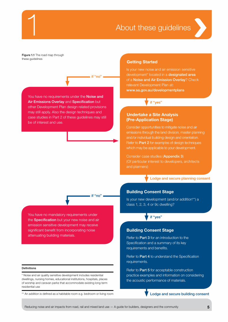
Refer to Figure 1.1 for a road map through these guidelines.
Reducing noise and air impacts from road, rail and mixed land use — A guide for builders, designers and the community 5
1
You have no mandatory requirements under the Specification but your new noise and air emission sensitive development may receive significant benefit from incorporating noise attenuating building materials.
Building Consent Stage
Is your new development (and/or addition**) a class 1, 2, 3, 4 or 9c dwelling?
Building Consent Stage
Refer to Part 3 for an introduction to the Specification and a summary of its key requirements and benefits.
Refer to Part 4 to understand the Specification requirements.
Refer to Part 5 for acceptable construction practice examples and information on considering the acoustic performance of materials.
You have no requirements under the Noise and Air Emissions Overlay and Specification but other Development Plan design related provisions may still apply. Also the design techniques and case studies in Part 2 of these guidelines may still be of interest and use.
Getting Started
Is your new noise and air emission sensitive development* located in a designated area of a Noise and Air Emission Overlay? Check relevant Development Plan at: www.sa.gov.au/developmentplans
Undertake a Site Analysis (Pre-Application Stage)
Consider opportunities to mitigate noise and air emissions through the land division, master planning and/or individual building design and orientation. Refer to Part 2 for examples of design techniques which may be applicable to your development.
Consider case studies (Appendix 3) (Of particular interest to developers, architects and planners)
About these guidelines
Definitions
* Noise and air quality sensitive development includes residential dwellings, nursing homes, educational institutions, hospitals, places of worship and caravan parks that accommodate existing long-term residential use
** An addition is defined as a habitable room e.g. bedroom or living room
if “no”
if “no”
if “yes”
if “yes”
Lodge and secure planning consent
Lodge and secure building consent
Figure 1.1 The road map through these guidelines

Reducing noise and air impacts from road, rail and mixed land use — A guide for builders, designers and the community6
1About these guidelines
1.5 Strategic planning contextIn South Australia, and especially the Greater Adelaide region, significant demographic change and population increase are likely over the coming decades.
The 30-Year Plan for Greater Adelaide envisions a new urban form to accommodate the anticipated increase in housing demand to follow. Similarly, the urban form of regional centres and townships in some regional areas of the State could change.
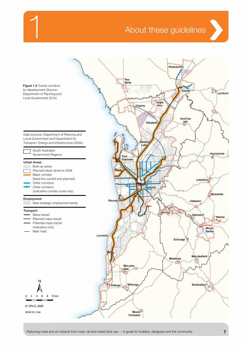
This new urban form means that a higher proportion of new housing in Greater Adelaide will be located within existing urban areas rather than in green-field areas (Figure 1.3). Mixed-use development will combine residential, commercial, retail and recreational facilities located around public transport nodes, corridors and activity centres. Higher density, mixed-use development will help create liveable, vibrant and accessible communities while reducing urban sprawl and encroachment on productive land.
The South Australian Government has introduced the Overlay and the Specification to ensure that the new urban form supports the health and wellbeing of residents.
1.6 Understanding NoiseDecibels (dB(A)) are used to measure how loud a sound is or the level of sound pressure. A zero decibel level corresponds to the threshold of human hearing (Vic Roads 2003). The list below gives you an idea of how noticeable a change in decibel level will be to you:
• 1dB - Not noticeable
• 3dB - Barely noticeable
• 5dB - Clearly noticeable change
• 10dB - About twice as loud
• 20dB - About four times as loud
Sound level, though, is not the only important element to consider. This is because, even at low volume, a sound may be annoying due to the characteristic of the noise such as pitch, duration, impulsiveness or how frequently it occurs (Adelaide City Council).
Figure 1.2 Some typical noise sources and their sound pressures (noise level). Source: Adapted from Bies D.A and Hansen C.H, Engineering Noise Control: Theory and Practice as cited in Adelaide City Council’s Noise Technical Information Sheet 8
Intolerable 120 Rock concert
110 Accelerating motorcycle (at five metres), jet aircraft, amplified music
Very Noisy 100 Pneumatic hammer (at two metres), passing train
90 Loud factory, dog barking
Noisy 80 Kerbside of busy street, shouting
70 Busy traffic
60 Department store, Speech Level
50 Quiet restaurant
Quiet 40 Residential area at night
30 Theatre
Very Quiet 20 Rustling of leaves, whisper
10 Human breathing (at three metres)
0
dB levels
Threshold of hearing
Reducing noise and air impacts from road, rail and mixed land use — A guide for builders, designers and the community 7
1 About these guidelines
Figure 1.3 Transit corridors for development (Source: Department of Planning and Local Government 2010)
Data sources: Department of Planning and Local Government and Department for Transport, Energy and Infrastructure (2009).
South Australian Government Regions
Urban Areas Built-up areas Planned urban lands to 2038 Major corridor (fixed line current and planned) Other corridors Other corridors (indicative corridor route only)
Employment New strategic employment lands
Transport Mass transit Planned mass transit Potential mass transit (indicative only) Main road
S549
A19
A705
A2
A14
A17
A7
A2
S1627
A50
A53
S1628
A13
Q40
A4
S1641
S1601
A117
S1640
A25
PO
RT
RD
WEST THEBARTON RD
MANNDR
FIRSTST
TR
EM
BAT
HS
T
BARNARD ST
BUXTON ST
GIL
BE
RT
ST
DRAYTO
NST
MOLESWORTH ST
CHAPEL S
HO
LD
EN
ST
HAW
KERST
CA
PP
ER
DR
DRAYTO
NST
ANNEST
BALLANTYNE ST
SMITH ST
TELFORD
ST
LIGHT TCE
BROW
NST
ALB
ER
TS
T
PORTRD
ADAM ST
RICHARD ST
PO
RT
RD
FLO
REN
CE
CR
SUSAN ST
WA
RE
ST
PICKERIN
GST
TAYLO
RSTHO
CKING
ST
COG
LIN
ST
NE
VI L LE
RD
ALBERTST
THIRTEENTHST
EASTST
ROSE
ST
TENTHST
STRANGWAYS TCE
ORSMONDST
WA
LS
HS
T
MU
RR
AY
ST
WEST
ST
GIB
BO
NL
AN
E
SECONDST
WEST
ST
FIRSTST
CHIEF
ST
EIGHTHST
ETHELBERT SQ
NINTHST
GIB
SON
ST
THIRD ST
FIELD
ST
ANDERSON ST
BENNETT ST
AN
NS
T
HO
LLAN
DS
T
BR
OW
NS
T
LOW
ES
T
DOVE ST
REID ST
QUIN
ST
NILE
ST
PHILLIPS ST
AN
NN
ELS
ON
DR
GU
TH
RIE
S
RO
NA
LDS
T
MARY
ST
MIL
NER
STCRAW
FOR
DLA
NE
GEO
RG
EST
ELEVENTHST
RIDLEYST
SCAMMELLLANE
ROSS ST FIL
SE
LLS
T
THIRDST
FOURTHST
SIXTHST
FIFTHST
SEVENTHST
WA
RM
EM
OR
IAL
DR
BA
CO
NS
T
J AM
ES
ST
DA
LGL
EIS
HS
T
CA
WT
HO
RN
ES
T
LIVINGSTONE ST
WALTER ST
OS
MA
N
PL
QU
EE
NS
T
RANDOLPH ST
RIVER ST
DE
WS
TS
TIR
LIN
GS
T
GA
OL
RD
MILLS
TC
E
PA
RK
TC
E
A D A M
S T
SO
UT
HR
D
MA
NT
ON
ST
WestTorrensCouncil
AdelaideCouncil
DEVELOPMENT CONSTRAINTSCHARLES STURT COUNCIL
Overlay Map ChSt
±0 500 m
Development Plan Boundary
Designated Area
Train Line
Tram Line
Designated Road: type A road
Reducing noise and air impacts from road, rail and mixed land use — A guide for builders, designers and the community8
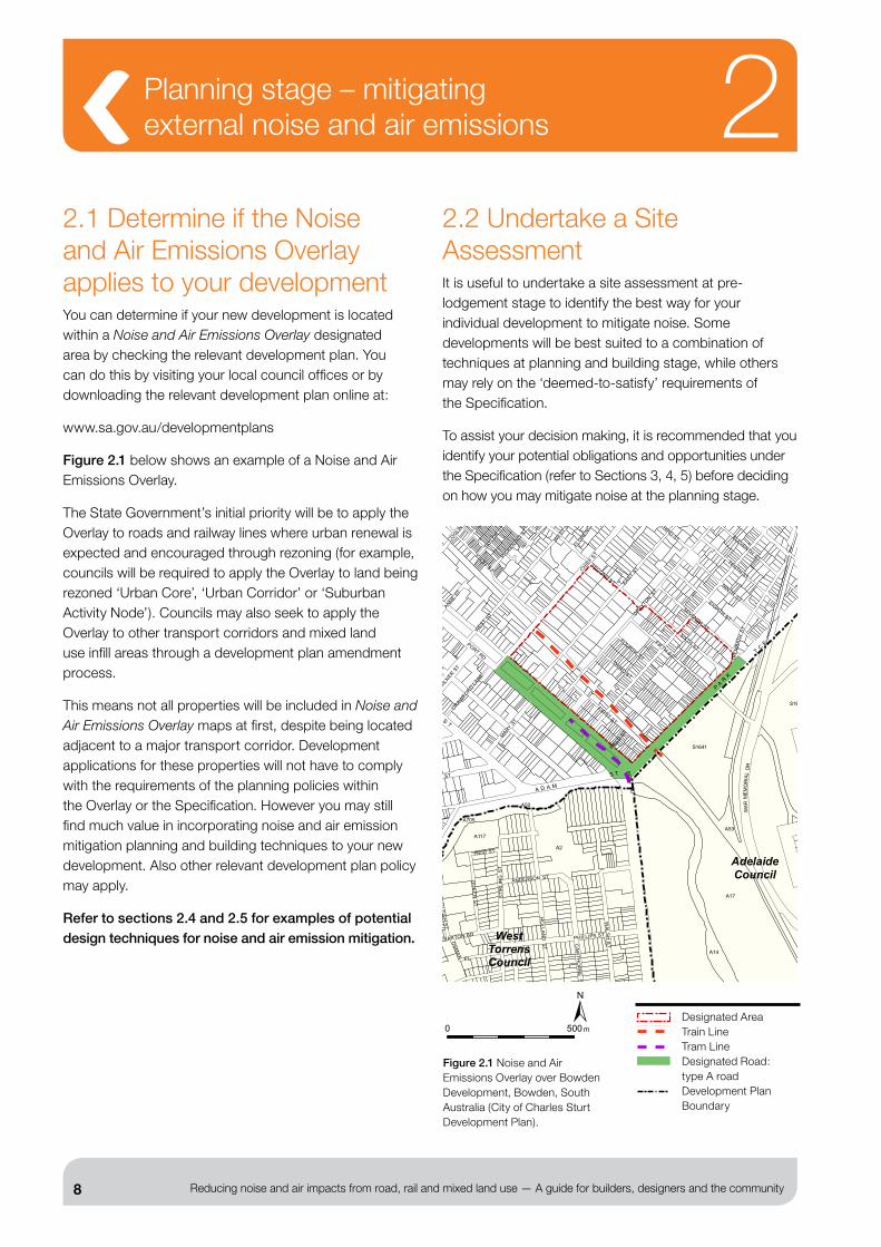
2.1 Determine if the Noise and Air Emissions Overlay applies to your developmentYou can determine if your new development is located within a Noise and Air Emissions Overlay designated area by checking the relevant development plan. You can do this by visiting your local council offices or by downloading the relevant development plan online at:
www.sa.gov.au/developmentplans
Figure 2.1 below shows an example of a Noise and Air Emissions Overlay.
The State Government’s initial priority will be to apply the Overlay to roads and railway lines where urban renewal is expected and encouraged through rezoning (for example, councils will be required to apply the Overlay to land being rezoned ‘Urban Core’, ‘Urban Corridor’ or ‘Suburban Activity Node’). Councils may also seek to apply the Overlay to other transport corridors and mixed land use infill areas through a development plan amendment process.
This means not all properties will be included in Noise and Air Emissions Overlay maps at first, despite being located adjacent to a major transport corridor. Development applications for these properties will not have to comply with the requirements of the planning policies within the Overlay or the Specification. However you may still find much value in incorporating noise and air emission mitigation planning and building techniques to your new development. Also other relevant development plan policy may apply.
Refer to sections 2.4 and 2.5 for examples of potential design techniques for noise and air emission mitigation.
Figure 2.1 Noise and Air Emissions Overlay over Bowden Development, Bowden, South Australia (City of Charles Sturt Development Plan).
Designated Area Train Line Tram Line Designated Road: type A road Development Plan Boundary
S549
A19
A705
A2
A14
A17
A7
A2
S1627
A50
A53
S1628
A13
Q40
A4
S1641
S1601
A117
S1640
A25
PO
RT
RD
WEST THEBARTON RD
MANNDR
FIRSTST
TR
EM
BAT
HS
T
BARNARD ST
BUXTON ST
GIL
BE
RT
ST
DRAYTO
NST
MOLESWORTH ST
CHAPEL S
HO
LD
EN
ST
HAW
KERST
CA
PP
ER
DR
DRAYTO
NST
ANNEST
BALLANTYNE ST
SMITH ST
TELFORD
ST
LIGHT TCE
BROW
NST
ALB
ER
TS
T
PORTRD
ADAM ST
RICHARD ST
PO
RT
RD
FLO
REN
CE
CR
SUSAN ST
WA
RE
ST
PICKERIN
GST
TAYLO
RSTHO
CKING
ST
COG
LIN
ST
NE
VI L LE
RD
ALBERTST
THIRTEENTHST
EASTST
ROSE
ST
TENTHST
STRANGWAYS TCE
ORSMONDST
WA
LS
HS
T
MU
RR
AY
ST
WEST
ST
GIB
BO
NL
AN
E
SECONDST
WEST
ST
FIRSTST
CHIEF
ST
EIGHTHST
ETHELBERT SQ
NINTHST
GIB
SON
ST
THIRD ST
FIELD
ST
ANDERSON ST
BENNETT ST
AN
NS
T
HO
LLAN
DS
T
BR
OW
NS
T
LOW
ES
T
DOVE ST
REID ST
QUIN
ST
NILE
ST
PHILLIPS ST
AN
NN
ELS
ON
DR
GU
TH
RIE
S
RO
NA
LDS
T
MARY
ST
MIL
NER
STCRAW
FOR
DLA
NE
GEO
RG
EST
ELEVENTHST
RIDLEYST
SCAMMELLLANE
ROSS ST FIL
SE
LLS
T
THIRDST
FOURTHST
SIXTHST
FIFTHST
SEVENTHST
WA
RM
EM
OR
IAL
DR
BA
CO
NS
T
J AM
ES
ST
DA
LGL
EIS
HS
T
CA
WT
HO
RN
ES
T
LIVINGSTONE ST
WALTER ST
OS
MA
N
PL
QU
EE
NS
T
RANDOLPH ST
RIVER ST
DE
WS
TS
TIR
LIN
GS
T
GA
OL
RD
MILLS
TC
E
PA
RK
TC
E
A D A M
S TS
OU
TH
RD
MA
NT
ON
ST
WestTorrensCouncil
AdelaideCouncil
DEVELOPMENT CONSTRAINTSCHARLES STURT COUNCIL
Overlay Map ChSt
±0 500 m
Development Plan Boundary
Designated Area
Train Line
Tram Line
Designated Road: type A road
S549
A19
A705
A2
A14
A17
A7
A2
S1627
A50
A53
S1628
A13
Q40
A4
S1641
S1601
A117
S1640
A25
PO
RT
RD
WEST THEBARTON RD
MANNDR
FIRSTST
TR
EM
BAT
HS
T
BARNARD ST
BUXTON ST
GIL
BE
RT
ST
DRAYTO
NST
MOLESWORTH ST
CHAPEL S
HO
LD
EN
ST
HAW
KERST
CA
PP
ER
DR
DRAYTO
NST
ANNEST
BALLANTYNE ST
SMITH ST
TELFORD
ST
LIGHT TCE
BROW
NST
ALB
ER
TS
T
PORTRD
ADAM ST
RICHARD ST
PO
RT
RD
FLO
REN
CE
CR
SUSAN ST
WA
RE
ST
PICKERIN
GST
TAYLO
RSTHO
CKING
ST
COG
LIN
ST
NE
VI L LE
RD
ALBERTST
THIRTEENTHST
EASTST
ROSE
ST
TENTHST
STRANGWAYS TCE
ORSMONDST
WA
LS
HS
T
MU
RR
AY
ST
WEST
ST
GIB
BO
NL
AN
E
SECONDST
WEST
ST
FIRSTST
CHIEF
ST
EIGHTHST
ETHELBERT SQ
NINTHST
GIB
SON
ST
THIRD ST
FIELD
ST
ANDERSON ST
BENNETT ST
AN
NS
T
HO
LLAN
DS
T
BR
OW
NS
T
LOW
ES
T
DOVE ST
REID ST
QUIN
ST
NILE
ST
PHILLIPS ST
AN
NN
ELS
ON
DR
GU
TH
RIE
S
RO
NA
LDS
T
MARY
ST
MIL
NER
STCRAW
FOR
DLA
NE
GEO
RG
EST
ELEVENTHST
RIDLEYST
SCAMMELLLANE
ROSS ST FIL
SE
LLS
T
THIRDST
FOURTHST
SIXTHST
FIFTHST
SEVENTHST
WA
RM
EM
OR
IAL
DR
BA
CO
NS
T
J AM
ES
ST
DA
LGL
EIS
HS
T
CA
WT
HO
RN
ES
T
LIVINGSTONE ST
WALTER ST
OS
MA
N
PL
QU
EE
NS
T
RANDOLPH ST
RIVER ST
DE
WS
TS
TIR
LIN
GS
T
GA
OL
RD
MILLS
TC
E
PA
RK
TC
E
A D A M
S T
SO
UT
HR
D
MA
NT
ON
ST
WestTorrensCouncil
AdelaideCouncil
DEVELOPMENT CONSTRAINTSCHARLES STURT COUNCIL
Overlay Map ChSt
±0 500 m
Development Plan Boundary
Designated Area
Train Line
Tram Line
Designated Road: type A road
2.2 Undertake a Site AssessmentIt is useful to undertake a site assessment at pre-lodgement stage to identify the best way for your individual development to mitigate noise. Some developments will be best suited to a combination of techniques at planning and building stage, while others may rely on the ‘deemed-to-satisfy’ requirements of the Specification.
To assist your decision making, it is recommended that you identify your potential obligations and opportunities under the Specification (refer to Sections 3, 4, 5) before deciding on how you may mitigate noise at the planning stage.
2Planning stage – mitigating external noise and air emissions

Reducing noise and air impacts from road, rail and mixed land use — A guide for builders, designers and the community 9
2.3 Subdivision, master planning and new land releaseWhen planning major renewal of areas or the subdivision of land located near busy roads or rail corridors, potential noise and air pollution sources should be considered at the master planning/concept planning stage. At this stage there is more opportunity to address these issues through setbacks, building orientation, layout or noise barriers. In some cases, it might be appropriate to design open spaces adjacent residential uses to reduce noise and air emission exposure. These public open space areas could also include appropriate bunding3 to buffer adverse noise impacts and to provide cycle and pedestrian paths along the road/ railway line to improve accessibility. However it is also important to include areas of public space which are protected from noise and air emissions. Refer to Figure 2.2 and the Urban Core case study in Appendix 3 for more information. At this stage, it is also important to identify if there are any existing entertainment venues and refer to page Part 4 of these Guidelines for additional information.
2.4 Design techniques for external noise control This section discusses the following potential noise design techniques:
• separation distance and land buffers
• location of private and communal open space
• building layout and orientation
• podiums and balconies
• trees and landscaping
• external noise walls, mounds and screens.
It is important to also balance the local environment, site constraints and other essential planning policy considerations of the particular zone (e.g. desired character, crime prevention, active street frontages and built form).
The characteristics of an individual development (such as distance from a noise source, topography and development type) will mean that different types of design techniques (or combinations) may be appropriate or applicable.
Figure 2.2 Example of potential opportunities to mitigate impact of noise and air emissions at master planning stage
1) Rail corridor
2) Village green Buffer residential dwellings through location of landscaped urban plaza for public gathering and linked to pedestrian/cycle networks
3) Road corridor
4) Mixed use development Locate retail and/or commercial uses adjacent to noise source to shield residential
5) Public open space Open space located away from main air and noise emission sources
12
3
4
5
3 Bunds are constructed mounds of earth covered in vegetation (usually shrubs and trees). The bunds can be a lot more aesthetically pleasing then high fencing barriers.
2 Planning stage – mitigating external noise and air emissions

Reserve acts as a buffer, playground and linking pedestrian and cycle paths
Cycling path
Main Road
Earth mound with noise wall on top
Planting trees and shribs provides a visual barrierand absorbs particulates in air emissions from vehicles
Reserve
N
Reducing noise and air impacts from road, rail and mixed land use — A guide for builders, designers and the community10
Figure 2.3 An example of low density housing adjacent to an expressway with a noise barrier and separation distance to reduce the effects of noise and air emissions
2.4.1 Separation distance and land buffersIn the case of a new green or brown field development, setting back the edge of the subdivision from the transport corridor could allow for a greenway4 to act as a buffer between the corridor and residential area. A vegetated buffer can reduce the impact of traffic noise and confer both physical and psychological protection from vehicle emissions. These spaces can be designed to provide walking and cycling paths adjacent to the road or rail line, to improve accessibility (Figure 2.3). Refer to case study 4 (Appendix 3) for further information.
4 Greenways are dedicated walking and cycling routes following major transport corridors or linear open space to improve access to homes, shops, workplaces and public transport.
2Planning stage – mitigating external noise and air emissions

Courtyard
Courtyard
Road
Noise source
Reducing noise and air impacts from road, rail and mixed land use — A guide for builders, designers and the community 11
Figure 2.5 Apartment plan with noise sensitive rooms away from the noise source
Figure 2.4 ‘U’ or ‘L’ shaped layouts to protect outdoor space from noise and air emissions
2.4.2 Location of private and communal open spacePrivate outdoor recreation areas, such as courtyards, are not affected by the Specification but are important spaces for domestic living. The impact of transport noise and air emissions can be reduced in several ways, for example:
• increasing the distance between the road/railway and the recreation area
• locating courtyards or balconies away from the noise and emissions source
• using buildings in ‘U’ or ‘L’ shaped layouts to create sheltered outdoor recreation areas protected from noise (Figure 2.4).
2.4.3 Building layout and orientationLocating noise sensitive rooms such as living rooms and bedrooms away from the facade exposed to the noise source (e.g. on the opposite side of the dwelling) can lower the level of noise treatment needed for these rooms (Figures 2.6).
Less noise sensitive rooms, such as bathrooms, laundries, corridors and stairwells can be located on the side more affected by noise to act as noise buffers. This may not always be a practical or desired solution, particularly where there are other design reasons for locating living areas towards the more noise affected façade (e.g. to maximise views). In these situations, applicants may choose to rely solely on the construction requirements (e.g. insulation and window glazing) of the Specification (see Section 3) to mitigate noise.
2 Planning stage – mitigating external noise and air emissions

Reducing noise and air impacts from road, rail and mixed land use — A guide for builders, designers and the community12
Planning stage – mitigating external noise and air emissions 2
2.4.4 Podiums and balconies For medium to high rise5 mixed-use development, podiums can be used to shield residential levels above from noise. Non-residential uses at ground level, such as commercial or retail at the front of the site, with residential floors set back, will increase the separation distance and shield the upper floors from the noise source (Figure 2.6 and 2.7). It can also help activate the streetscape if well designed. Commercial and retail buildings do not have any obligations under the Specification.
Standard jutting balconies may act to reflect noise directly into the interior of the dwelling from the balcony above. Design features to help control noise and air quality impacts include:
• planters or vertical garden elements in the balcony design, as an aesthetically appealing visual and pollutant filter between dwelling occupants and the road
• balcony and terrace soffits6 lined with acoustic panels to absorb sound and reduce sound reflection back into the dwelling (Figure 2.8)
• solid balustrades incorporated into balconies as a shield to the noise source below (Figure 2.9)
• use of ‘winter garden’ balconies with operable glass screens (e.g. bi-folds) that can create a fully enclosed indoor/outdoor space (Figure 2.10).
Figure 2.6 An example of a residential apartment building with a podium (restaurant) at ground floor level
5 The 30-Year Plan for Greater Adelaide defines ‘low rise’ as 1-3 storeys, ‘medium rise’ as 4-9 storeys and ‘high rise’ as more than 10 storeys.
6 The term soffit refers to the underside of any construction element, such as a balcony or roof eaves.

Podium acts as a noise shield
Apartments protected from noise
by podium below
As below + higher solid balustrade
Closed solid balustrade with sound absorption
to balcony soffit
Closed solid balustrade
Standard open balustrade
Thick solid wall with fewer penetrations
Reducing noise and air impacts from road, rail and mixed land use — A guide for builders, designers and the community 13
Planning stage – mitigating external noise and air emissions2
Figure 2.7 Podiums act to shield upper floors (Source: NSW Department of Planning 2008)
Figure 2.9 Balcony design and noise mitigation treatment options (Source: NSW Department of Planning 2008)
Figure 2.8 Deep balconies with solid balustrades protect from noise coming from street level (Source: Renewal SA)
Figure 2.10 Enclosed balconies (or winter gardens) are another way of reducing noise entering the dwelling. Bi-fold glass windows allow natural ventilation when the weather permits.

Reducing noise and air impacts from road, rail and mixed land use — A guide for builders, designers and the community14
Planning stage – mitigating external noise and air emissions 2
2.4.6 Trees and landscapingWhere space permits, trees and shrubs can make effective noise barriers and at the same time be visually attractive. They can also soften the appearance of noise walls.
The results of research on the effectiveness of tree and shrub barriers vary enormously but in some cases, noise can be reduced by five decibels (dB) over a distance of 30 metres where planting is particularly dense (US Department of Transportation, 2012). However, it is usually not feasible to plant enough trees and other vegetation along a road to achieve such a reduction. Therefore while trees and other vegetation will greatly improve the amenity of the area and provide psychological relief, they often will not significantly physically lessen the impact of noise significantly.
In order for a vegetation buffer to be most effective as a noise reducer, the following principles apply (Medway Council, 2012):
• plant trees with dense foliage and branches that reach close to the ground or plant an under-storey of dense shrubs or a surrounding hedge
• plant the vegetation as close to the noise source as possible
• the wider the belt of trees, the greater the noise reduction
• at least 15-30 metres wide and 4-5 metres tall (Vic Roads, 2003)
• ensure that there are no gaps to reduce noise penetration
• use broad-leaved evergreens for year-round noise screening
• cultivating ground before planting and the addition of well-rotted organic matter to the soil surface, may also help to reduce noise while vegetation becomes established
• noise reduction tends to increase with tree height up to 10-12 metre after which it tends to decrease. This is probably a result of lower branches dying and allowing sound to travel more easily.
Figure 2.11 Example of use of trees as a sound barrier
2.4.7 External noise walls, mounds and screensIn situations such as residential development located adjacent to an expressway, construction of an earth mound, solid wall or fence between the noise source and the dwelling is necessary as building treatments on their own will not provide an acceptable level of amenity to dwelling occupants. The barrier will be acoustically effective if it breaks the line of sight between the dwelling and the noise source. In some cases, a noise barrier located close to the noise source, with the dwelling behind, will reduce the noise sufficiently on its own, without further need for compliance with the Specification.
To be acoustically effective the following key principles apply:
• barriers must block the line of sight between the dwelling and the noise source
• barriers should be located as close as possible to the noise source
• development positioned lower than the barrier will be more effective
• the taller the barrier, the greater the noise reduction
• the longer the barrier, the more effective – barriers should ideally extend far beyond the edges of the development
• barriers need to be continuous with no gaps, as gaps will significantly reduce its noise reduction ability
• materials used in the barrier must have a surface density of at least 20kg/m2.

Reducing noise and air impacts from road, rail and mixed land use — A guide for builders, designers and the community 15
2 Planning stage – mitigating external noise and air emissions
Earth mounds
Where space permits, raised mounds of earth can be effective noise barriers alone or combine well with a wall on top to reduce the overall area of the mound and the height of the wall. This combination also allows for vegetation to be planted on the mound (Figure 2.12).
Walls
In areas where groups of dwellings are located adjacent to a new or upgraded roadway, walls built as roadside barriers can be an effective form of noise mitigation.
Many materials can be suitable for noise mitigation walls but as a rule of thumb, the denser the material, the better the noise reduction. The table in Appendix 2 outlines the pros and cons of different types of walls. Figures 2.13, 2.14, 2.15 and 2.16 show examples of materials often used for noise barriers.
Figure 2.12 A combination of earth mounds and noise walls allows room for screening vegetation to be planted
Figure 2.13 Precast lightweight concrete panels used as noise barriers are effective, highly durable and not easily damaged
Figure 2.14 Timber incorporating clear panels for pedestrians and cyclists

Reducing noise and air impacts from road, rail and mixed land use — A guide for builders, designers and the community16
Fences
Light weight fences, such as colorbond steel (Figure 2.17) or timber (Figure 2.18) can be effective in reducing lower levels of noise but due to their lower density, will be less effective than a more solid wall such as brick or concrete.
Which features make a light-weight fence an effective noise barrier?
• Planks or sheeting must be tight fitting, with no gaps between materials or between the base of the fence and the ground (e.g. Figures 2.19 and 2.20).
• To avoid gaps emerging as materials age, place the posts close together (less than every 2.5m) for rigidity and with three horizontal support rails.
• Overlay horizontal or vertical planks by a minimum of 35mm.
• Use galvanised bolts and nails.
• Use seasoned and treated timber to minimise shrinkage and increase the life of the timber.
• Ensure the barrier is of adequate length to provide at least 160 degrees of protection, or extend down side boundaries (Figure 2.21).
• Consider overlapping barrier sections to provide access without compromising acoustic protection (e.g. Figure 2.22).
Planning stage – mitigating external noise and air emissions 2
Figure 2.16 Walls made from precast concrete panels provide opportunities for urban design themes such as this one on the Gallipoli Underpass.
Figure 2.15 A combination of transparent materials on top of an opaque base allows natural light to pass through the barrier
Figure 2.17 Colorbond fencing up to 2.4m in height can be an effective noise barrier. Above 2.4m, thicker sheets would have to be used to provide the required noise reduction
Figure 2.18 Example of a combination of timber and colorbond fence

Reducing noise and air impacts from road, rail and mixed land use — A guide for builders, designers and the community 17
2 Planning stage – mitigating external noise and air emissions
20mm Thickness
Solid Timber Fencing
Nail
Two layers of sheet steel fencing
Barrier
160˚
Barrier
Access
Figure 2.19 To be effective barriers to noise, timber fences must have no gaps between the boards or at the base of the fence (Source: NSW Department of Planning 2008)
Figure 2.21 To be effective, fences should be long enough to provide at least 160 degrees of protection, or extend down side boundaries
Figure 2.20 Doubling the layers of colorbond improves the fence’s acoustic properties (Source: NSW Department of Planning 2008)
Figure 2.22 Overlapping barrier sections can be used to provide access without compromising acoustic protection

Reducing noise and air impacts from road, rail and mixed land use — A guide for builders, designers and the community18
Noise & air quality affected zone Quiet zone (eg. outdoor recreational area)
Figure 2.23 Outdoor spaces located away from noise and emissions (Source: NSW Department of Planning 2008)
2.5.1 Protection of private and communal open space from air emissionsPrivate and communal outdoor spaces, such as courtyards, are important spaces for everyday domestic living. External noise and air emissions can be reduced in these areas through:
• locating ground level private and communal open space away from the emission source (Figure 2.23)
• avoiding the use of confined outdoor spaces oriented towards primary roads that can trap polluted air and restrict air circulation.
2.5 Design techniques for external air quality controlDevelopments located next to busy roads or railway lines can have challenges in providing an acceptable level of air quality for residents and visitors. Air quality can be addressed through building and streetscape design which increases the dispersal of pollutants.
Air quality should be a design consideration on high traffic volume roads and roads with significant traffic congestion in peak periods.
Consideration should be given to locating air conditioning intakes away from these roads as well as areas where vehicles idle, such as delivery areas in commercial precincts.
Planning stage – mitigating external noise and air emissions 2

Reducing noise and air impacts from road, rail and mixed land use — A guide for builders, designers and the community 19
2.5.2 Building design elements to disperse air pollutantsA streetscape with continuous flat façades, without surface changes, of two or more storeys such as terrace housing or apartments tends to cause noise to reverberate between the two frontages. Similarly, road ‘canyons’ may channel winds or prevent them from reaching road level depending on their shape, dimension and orientation. The more confined a space is by buildings, walls or embankments adjacent to or over a roadway, the less opportunity air pollutants have to disperse (Figure 2.24).
Dispersal can be encouraged by:
• having fewer confined areas to enable winds and breezes to disperse and carry away air pollutants (i.e. carefully consider the orientation and continuity of open spaces, their dimension and shape, topography and the layout of buildings surrounding the area)
• stepping back the upper storeys of roadside buildings to increase dispersion of air pollutants
• providing a variety in frontages such as setting upper floors back from the street frontage helps disperse air and noise (Figure 2.25)
• using two-sided balconies will allow more cross breezes (Figure 2.26).
Street
Street
Figure 2.24 Road canyons created by long expanses of flat facades can cause air to become trapped and concentrated (Source: NSW Department of Planning 2008)
Figure 2.25 Variation in building facades increases the dispersion of air pollutants and reduces the effects of canyoning (Source: NSW Department of Planning 2008)
Figure 2.26 Two-sided balconies for cross breezes
2 Planning stage – mitigating external noise and air emissions

Reducing noise and air impacts from road, rail and mixed land use — A guide for builders, designers and the community20
Planning stage – mitigating external noise and air emissions 2
2.5.3 The role of trees and landscapingIt is important to consider the positive role that trees can have in noise and air quality sensitive developments. As well as greatly improving amenity in higher density areas, promoting urban cooling, improving walkability and providing psychological relief from noise; trees confer a number of other benefits to the health, liveability, and marketability of a development. Trees also have the added benefit of improving aesthetics and minimising the visual intrusion from adjacent rail or road corridor. There is as yet insufficient evidence that trees have a significant impact on the removal of particulate matter (PM2.5) from vehicles or other sources.
Figure 2.27 Trees in median strips and footpaths help minimise the visual intrusion from roads and rail corridors.

Air inlets
Reducing noise and air impacts from road, rail and mixed land use — A guide for builders, designers and the community 21
2 Planning stage – mitigating external noise and air emissions
Figure 2.28 Locate air intake grills away from the source of polluted air (Source: DPTI 2012a)
2.5.4 Air inlet positionsVentilation design and openable windows should be considered in the design of development located adjacent to transport emission sources. Locate air-conditioning air inlets away from high traffic roads or areas where vehicles idle.
2.6 Case studiesFour case studies have been developed by practitioners to demonstrate design and planning options for applying noise and air quality mitigation to various urban development types. They have also been peer reviewed by acoustic engineers.
The case studies were based on specific land use zones to identify different noise and air emission mitigation solutions that could be adopted in various planning policy settings.
Three of the case studies focus on primary design elements of a building (e.g. building form, orientation and layout) rather than secondary building elements (e.g. glazing types and insulation) as required under the Minister’s Specification SA 78B. They focus on the new zones released by DPTI in 2011 to support The 30-Year Plan for Greater Adelaide’s encouragement of new higher density and mixed use development adjacent to major transport corridors (e.g. rail and road).
The fourth case study focuses on the potential for noise barriers and separation buffers to protect low density residential development adjacent to major transport corridors.
In the case studies, noise and air quality objectives have been balanced with site constraints and other essential planning policy considerations (e.g. desired character, crime prevention, active street frontages, energy efficiency, interface height provisions and built form). The design seeks to address all requirements, rather than demonstrate an ideal noise and air quality solution. Each design response is just one of many ways to deal with these issues.
Appendix 3 has the full case studies.

Mitigating noise and air emissions from major transport corridors and mixed use development 22

Reducing noise and air impacts from road, rail and mixed land use — A guide for builders, designers and the community 23
3 Building rules to mitigate external sound
3.1 What is the Minister’s Specification SA 78B? The Minister’s Specification SA 78B – Construction Requirements for the Control of External Sound (the Specification) contains the mandatory construction requirements intended to protect the occupants of certain types of dwellings from the impact of existing and future noise from major roads, rail lines and mixed land uses such as entertainment venues.
The Specification is available at:
www.sa.gov.au/planning/ministersspecifications
3.2 What type of buildings does it apply to?The Specification applies to new Class 1, 2, 3, 4 and 9c dwellings, as defined in the Building Code of Australia (BCA), which are located within the designated area of a Noise and Air Emissions Overlay in the relevant council Development Plan. It also applies to certain additions made to these classes of buildings. A description of these classes of buildings can be found in Appendix 1.
3.3 What does it consist of?The Specification has three key components:
1. Performance criteria (Part B of the Specification) specify maximum internal sound levels for buildings exposed to noise from road, rail or mixed use development, such as entertainment venues. The internal sound levels specified are intended to provide an appropriate level of protection from annoyance and sleep disturbance caused by excessive external noise, which research has shown leads to both short and long term health problems.
2. Deemed-to-satisfy requirements (Part C of the Specification) provides acceptable construction practices for the parts of the building, including the floors, walls and roof; that separate the internal rooms of the dwelling from the external noise. These practices achieve the performance criteria specified in Part B. Examples are detailed in Part 3 of this guideline.
3. Verification method (Part B5 of the Specification) provides the opportunity to develop an alternative solution to the deemed-to-satisfy requirements. The applicant may choose to design their dwelling in consultation with a professional acoustic engineer, who will prepare a report that demonstrates compliance with the performance criteria. This approach allows more flexible design and building practices to be used.

Reducing noise and air impacts from road, rail and mixed land use — A guide for builders, designers and the community24
3Building rules to mitigate external sound
3.4 What are the different types of sound sources?Certain roads, rail corridors and entertainment venues are considered to be sound sources for the purposes of the Specification.
3.4.1 RoadsNoise and Air Emissions Overlay Maps in council Development Plans will identify the roads that have high levels of traffic movement and as a result, high levels of noise. The roads have been designated as Type A, Type B or Type R. Type A and B roads are metropolitan roads exposed to the average daily traffic volumes (as noted below) and freight routes. Type R roads are rural roads used as freight routes.
generally located in mixed land use zones. They will need to be identified on a case-by-case basis. However, venues such as pubs, clubs, motels and restaurants, which hold an entertainment licence under the Liquor Licensing Act, will be included as entertainment venues. Information on whether or not a venue is an entertainment venue can also be obtained from the local council. Dwellings located within 65m of the boundary of an existing entertainment venue will have a sound exposure category of 5.
3.5 What are the benefits?The Specification provides greater certainty for the building industry, consumers and occupants about the performance of dwellings exposed to external noise sources.
3.5.1 Benefits for buildersThe benefits for the building industry include:
• reduces red tape and simplifies the development assessment process
• provides certainty that the performance criteria in the Specification will be achieved
• eliminates (in most cases) the need for a separate acoustic report (does not apply to entertainment venues)
• provides cost-effective construction techniques that are based on current industry practice
• provides flexibility for more complex projects (and alternative methods of construction) by providing the option to seek an acoustic report
• increases dwelling marketability.
3.5.2 Benefits for consumers and occupants of dwellingsThe benefits for consumers and occupants of dwellings include:
• increased health and well being resulting from a decrease in sleep disturbance and general annoyance from external sound
• possible increase in energy efficiency
• possible increase in property value.
Type A roads
• 50,000 vehicles per day (vpd) and over; or
• a primary freight route.
Type B roads
• 25,000–49,999 vpd; or
• a Department of Planning, Transport and Infrastructure major traffic route or the basis for a growth corridor.
For a copy of the maps which show which roads will be potentially designated, view the Noise and Air Emissions Overlay 3 Technical Information sheet. This is available at:
www.sa.gov.au/planning/planningpolicies
3.4.2 Rail corridorsRail corridors have been designated as either train or tram lines in council Development Plans.
3.4.3 Entertainment venuesExisting entertainment venues are considered to be sound sources for the purposes of the Specification. They are not individually identified in council Development Plans but are

Reducing noise and air impacts from road, rail and mixed land use — A guide for builders, designers and the community 25
3 Building rules to mitigate external sound
Figure 3.1 Dwellings located within 65m of existing entertainment venues will have a sound exposure category of 5.

Reducing noise and air impacts from road, rail and mixed land use — A guide for builders, designers and the community26
Separation distanceB
B B
C
A A
B C
The measurement between B & Cis the separation distance
Separation distance
Transport corridor(includes footpaths)
Sound sourcelocation
3m 3m
Apartments
House
Transport corridor boundary Transport corridor boundary
4Applying the Specification
4.1 Steps on how to apply the SpecificationIf you are lodging an application for a new Class 1, 2, 3, 4 or 9c dwelling or an addition to one of these classes of building and the dwelling (or addition) is located within the designated area of the Noise and Air Emissions Overlay, the dwelling must be designed and constructed in accordance with the Minister’s Specification SA 78B– Construction Requirements for the Control of External Sound (the Specification).
For the purpose of the Specification, additions must comply if they include a habitable room (such as a bedroom or living room).
For a copy of the Specification visit:
www.sa.gov.au/planning/ministersspecifications
Figure 4.1 Measuring the sound source location and the separation distance for a dwelling at the same level as a transport corridor.
Step 1Determine the sound exposure category/ies for the dwelling (Part C3 of the Specification)
There are five sound exposure categories. Sound exposure category 1 is the least severe and sound exposure category 5 is the most severe. The Specification provides corresponding construction materials and techniques for categories 1 to 4 but category 5 must be dealt with by a professional acoustic engineer who will prepare a noise report.
Each part of the building containing a habitable room, that is exposed to a sound source must comply with the Specification. The categories that apply to the dwelling are determined by measuring the separation distance between the relevant sound source/s (road, rail, entertainment venue) and the dwelling. The sound exposure categories for road and rail sound are listed in Tables 6, 7 and 8 of the Specification.
To measure the separation distance, the location of the sound source must be established.
Transport corridors (roads and rail lines)For a site with little or no slope:
• Determine the sound source location Measure A to B from the nearest boundary of the transport corridor in 3 metres towards the road or rail line. Point B is the sound source location.
• Measure separation distance From point B (sound source) measure back to your building facade (C). The measurement between B and C gives you the separation distance.

Reducing noise and air impacts from road, rail and mixed land use — A guide for builders, designers and the community 27
Applying the Specification4
Townhouses(category 5)
Apartments(category 5)
Boundary
Retail Shops
65m65m
65m
Entertainmentvenue
Figure 4.3 Dwellings (and additions) located within 65m of the boundary of an existing entertainment venue will be sound exposure category 5
For a steeper site:
Figure 4.2 shows how the sound source location and the separation distance is determined for a site which is above or below the level of the road or rail line, or where the building has a staggered façade.
In this case the line of sight between the building façade and the sound source may be interrupted and shielded by the edge of the road or rail corridor or by the lower storeys of the building itself.
• Determine the sound source location and separation distance Take a straight line from the head height of the openings (windows and doors) for each storey (point A), to a point which is a minimum of 3m within the transport corridor (point B). The straight line must be an uninterrupted line of sight between point A on the building and the transport corridor. The position of point B is the sound source location and the measurement between point A and B is the separation distance.
Entertainment venues
The Specification requires that a dwelling (or addition) that is located within 65m of the boundary of an existing entertainment venue has a sound exposure category of 5 (Refer to 3.4.3 and Figure 4.3).
Separation distance 1
Separation distance 2
Separation distance 3
Head of windowsor doors
B
A
A
A
Transport corridor(includes footpaths)
3m
Apartments
Transport corridor boundary
Transport corridor boundary
Figure 4.2 Measuring the sound source and separation location for steeper sites

Reducing noise and air impacts from road, rail and mixed land use — A guide for builders, designers and the community28
Figure 4.5 Where a dwelling is exposed to more than one sound source, the higher sound exposure category applies.
15m
18m
Type ‘A’ Road
Cat. 2
So category 3 applies
Separation distance is taken from3m inside the rail corridorRail line
Cat. 3Footpath
Step 2Determine the airborne sound insulation ratings for the dwelling (Part C4 of the Specification)
When the sound exposure categories for the dwelling have been identified, the airborne sound insulation ratings can be determined for each part of the building (floors, walls, windows, external doors, roof); that separate the internal habitable rooms of the dwelling from the external sound source.
Dwellings with sound exposure category 4 may require a mechanical ventilation system to achieve the airborne sound insulation rating.
Dwellings with sound exposure category 5 must have their airborne sound insulation ratings determined by a professional acoustic engineer in accordance with the performance criteria.
4Applying the Specification
Figure 4.4 Parts of a dwelling not directly exposed to the sound source can have their sound exposure category reduced by one category
15m
3m
Allotment boundaryFootpath
Type ‘A’ Road
Cat. 2Cat. 2
Cat. 3Cat. 3
Cat. 3
Shielding considerations
Parts of a dwelling not directly exposed to a sound source, such as those located on the opposite side of the dwelling, are considered to be shielded by the building itself and will have a sound exposure category one less than the adjoining exposed part (Figure 4.4).
Multiple sound exposure category considerations
The Specification requires that if a dwelling is exposed to more than one sound source, which may result in conflicting sound exposure categories, the dwelling must be designed for the highest sound exposure category (Figure 4.5). Figures 7 and 8 in Appendix 1 of the Specification illustrate exposure and façade categories.

Reducing noise and air impacts from road, rail and mixed land use — A guide for builders, designers and the community 29
Step 3 Determine deemed-to-satisfy solutions (Part C5 of the Specification)
The acceptable construction practices provided achieve the airborne sound insulation ratings required by Part C4 of the Specification.
These practices have been developed assuming that a dwelling exists in isolation and is not shielded by any external structures such as noise walls, mounds or other buildings.
Where a dwelling is shielded by external structures, an alternative solution may be appropriate.
There are no acceptable construction practices in the Specification for dwellings or parts of dwellings that are sound exposure category 5. These will have to be designed by a professional acoustic engineer.
Deemed-to-satisfy or alternative solution?
Low rise detached or semi-detached dwellings (Class 1) are more likely to be designed and constructed using the deemed-to-satisfy solutions in the Specification. Many of the acceptable construction practices use standard construction materials and techniques which offer readily available building solutions. These are less complex and therefore more cost-effective.
Larger, more complex residential projects with multiple dwellings, such as high rise apartments (Class 2 and 3 dwellings), are more likely to be designed and constructed using an alternative solution. This process allows the designer to take into account more one-off, specialised and complex circumstances.
For further advice about the best option, speak to an architect, building designer or builder during the design stage. Further information about the details that will be required with an application can be obtained from council or a private certifier, whichever will be responsible for
undertaking the building rules assessment.
Information about alternative solutions and acoustic assessments
An alternative solution may be appropriate where a dwelling is shielded by an external structure such as a fence, wall, mound or another building from a sound source and the applicant wants these factors considered during the design and assessment of the dwelling.
External structures that are to be considered should be confirmed with the relevant council as desirable and acceptable in the proposed location. Some locations where the Specification will apply also encourage active street facades and clear lines of sight between the road/rail and dwellings. Therefore, the use of external structures such as solid walls or fences may not be appropriate.
In preparing an alternative solution, a professional acoustic engineer should be engaged to aid with the design and prepare an acoustic report to demonstrate compliance with the Specification. A professional acoustic engineer is defined by the Specification as:
a person who is, or is eligible to be, a member of the Australian Acoustical Society and the Institute of Engineers Australia.
Information required for building rules assessment
The information (drawings and specification) submitted to the council or private certifier should include the acceptable construction practices that will be incorporated in the dwelling. An example of the type of information that should be included can be found in Section 5 of these guidelines.
An alternative solution will generally require an acoustic report to be lodged as part of the information.
Applying the Specification4
Reducing noise and air impacts from road, rail and mixed land use — A guide for builders, designers and the community30
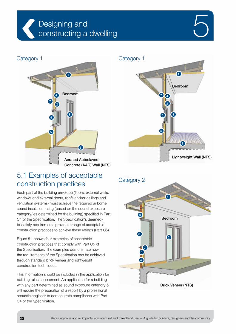
5.1 Examples of acceptable construction practicesEach part of the building envelope (floors, external walls, windows and external doors, roofs and/or ceilings and ventilation systems) must achieve the required airborne sound insulation rating (based on the sound exposure category/ies determined for the building) specified in Part C4 of the Specification. The Specification’s deemed-to-satisfy requirements provide a range of acceptable construction practices to achieve these ratings (Part C5).
Figure 5.1 shows four examples of acceptable construction practices that comply with Part C5 of the Specification. The examples demonstrate how the requirements of the Specification can be achieved through standard brick veneer and lightweight construction techniques.
This information should be included in the application for building rules assessment. An application for a building with any part determined as sound exposure category 5 will require the preparation of a report by a professional acoustic engineer to demonstrate compliance with Part C4 of the Specification.
Category 1
Bedroom
Aerated Autoclaved Concrete (AAC) Wall (NTS)
1
2
3
4
5
6
7
8
Category 1
Bedroom
Lightweight Wall (NTS)
1
2
3
4
5
6
7
8
5Designing and constructing a dwelling
Category 2
Bedroom
Brick Veneer (NTS)
1
2
3
4
5
6
7

Reducing noise and air impacts from road, rail and mixed land use — A guide for builders, designers and the community 31
Category 3
Bedroom
Brick Veneer (NTS)
1
2
3
4
5
6
7
8
Category 1 – AAC Wall1) There are no requirements for
ceilings and roofs2) Two layers of 16mm fire rated
plasterboard wall lining3) Minimum 10mm glazed
sliding door4) 90 x 45mm timber or steel
stud frame5) 75mm insulation with a
minimum density of 11kg/m3
6) Minimum 6mm glazed awning window for total glazing area between 40% and 60% of bedroom floor area
7) 75mm AAC wall panels installed to manufacturer’s detail
8) Concrete slab on ground or lightweight floor to comply with C5.2 of the Specification
Category 1 – Lightweight Wall1) There are no requirements for
ceilings and roofs2) Two layers of 16mm fire rated
plasterboard wall lining3) Minimum 10mm glazed side
hung door4) 90 x 45mm timber or steel
stud frame5) 75mm insulation with a
minimum density of 11kg/m3
6) Minimum 6mm glazed awning window for total glazing area between 40% and 60% of bedroom floor area
7) 9.5mm hardboard, 9mm fibre cement sheeting or 11mm fibre cement weatherboards fixed to resilient steel channels fixed to outside of stud frame
8) Concrete slab on ground or lightweight floor to comply with C5.2 of the Specification
Category 21) 10mm plasterboard ceilings.
with 165mm. Insulation to have a minimum density of 7kg/m3
2) 10mm plasterboard wall linings3) Minimum 10mm glazed side
hung door 4) 90mm clay brick masonry5) 75mm insulation with a
minimum density of 11 kg/m3
6) 70 x 35mm timber stud frame7) Minimum 10mm glazed awning
window for total glazing area between 40-60% of bedroom floor area
8) 25mm cavity9) Concrete slab on ground or
lightweight floor to comply with C5.2 of the Specification
Category 4
Bedroom
Brick Veneer (NTS)
1
2
3
4
5
6
7
8
Designing and constructing a dwelling5
Category 31) Two layers of 10mm
plasterboard or 1 layer of 16mm fire rated ceiling. Insulation to have a minimum density of 7kg/m3
2) 10mm plasterboard wall linings
3) Minimum 10mm glazed side hung door
4) 70 x 35mm timber stud frame5) 75mm insulation with a
minimum density of 11 kg/m3
6) 25mm cavity7) Minimum 10mm glazed awning
window for total glazing area between 20% and 40% of bedroom floor area
8) 90mm clay brick masonry9) Concrete slab on ground or
lightweight floor to comply with C5.2 of the Specification
Category 41) Two layers of 13mm fire
rated plasterboard ceilings supported on furring channels fixed to underside of joists or trusses (not on raked ceilings)
2) 10mm plasterboard wall linings3) External glass doors are not
permitted in category 4 4) 70 x 35mm timber stud frame5) 75mm insulation with a
minimum density of 11 kg/m3
6) 25mm cavity7) Area of glazing as a
percentage of the floor area limited to not more than 20% or use an alternative solution
8) 90mm clay brick masonry9) Concrete slab on ground or
lightweight floor to comply with C5.2 of the Specification
10) Ventilation system (not shown) to comply with C5.6.2 of the Specification
Figure 5.1 Examples of acceptable construction practices

Reducing noise and air impacts from road, rail and mixed land use — A guide for builders, designers and the community32
5.2 Considering the acoustic performance of materialsThe acceptable construction practices in the Specification provide several options to achieve the performance criteria for each part of the building envelope.
5.2.1 FloorsThe Specification permits the use of a concrete slab-on-ground that is in direct contact with the ground. Concrete is a high density material and provides high resistance to sound penetration. Suspended floors (concrete or lightweight systems) are also permitted.
5.2.2 External wallsThe Specification permits the use of a range of materials. Typically, walling materials with a high density, such as concrete and bricks, have better sound insulating properties. Lightweight materials, such as weatherboard or compressed fibreboard sheeting, have a lower density and perform less well. For this reason, the use of lightweight materials on walls that directly face sound sources should be limited.
Regardless of the wall material/s selected, the openings made in the external wall to accommodate windows, external doors and ventilation systems, create a point where sound has the opportunity to enter the building. For this reason, attention should be given to sealing around these openings (refer 5.2.3).
5.2.3 Windows and external doorsIn acoustic terms, glass (windows and external glass doors) is often the weakest part of the building envelope and can severely compromise an otherwise acoustically strong façade. Where glass is desirable in the building envelope (e.g. facing north for energy efficiency, or to capture a view), the Specification will require the thickness of the glass to be increased.
Where windows and external glass doors directly face the sound source, acoustic seals should be fitted to the frames to form a tight seal (Figures 5.2 and 5.3). Many commercially available glass windows and doors have acoustic seals with high sound insulating properties.
The main factors for a good acoustically performing door are the density, the thickness and the installation of airtight seals around the perimeter of the door (Figure 5.6). Good acoustic performance is also linked with ensuring there are no gaps from the outside so the use of cat flaps, letter box openings and other apertures should be avoided.
Pressure seal
Glass frame seal
Mastic
Window Sill
Sliding window frame
Sliding window edge
Glazing
Figure 5.2 Overhead section showing the operation of a vinyl fin seal for a sliding door or window. The vinyl fin must be in contact the window frame. (Source: DPTI 2012a)
Figure 5.3 Section showing the positions of window seals for good acoustic performance (Source: NSW Department of Planning 2008)
5Designing and constructing a dwelling

Reducing noise and air impacts from road, rail and mixed land use — A guide for builders, designers and the community 33
5.2.4 Roof and ceiling construction Flat roofs or roofs protected by a parapet wall may be less exposed to a sound source than pitched roofs. Pitched roofs covered with roof sheet (steel or similar) or tiles are similar in acoustic performance.
The Specification requires the addition of sound absorbent insulation material in the roof cavity, both below the roof and on top of the ceiling. This will significantly improve the roof’s acoustic performance, as will increasing the mass of the ceiling, with additional layers of, for example, plaster board. Figure 5.5 shows roof and ceiling treatments ranging from low to high performance.
5.2.5 VentilationWhere windows are required to be closed, an alternative ventilation system to provide fresh air must be installed. In many cases this requirement will only be achieved by a mechanical ventilation system that complies with Australian Standard 1668: The use of ventilation and air-conditioning in buildings.
Low performance Medium performance High performance
Steel Sheeting /Tiles on Battens
Roof sarking
Rafters
Ceiling Joist
Add insulationbelow roof
Add insulationbelow roof
Add insulationabove ceiling Add insulation
above ceiling &increase ceiling mass
(two layers of plasterboard)
Add insulationbelow roof
Plasterboard
Figure 5.5 Options for roof and ceiling treatments for acoustic performance (Source: NSW Department of Planning 2008)
Door / frameacoustic seal
Door / frameacoustic seal
Frame / surroundsealant (mastic)
Frame / surroundsealant (mastic)
Avoid keyholes
Door thresholdacoustic seals
Door thresholdacoustic seals
Threshold / floor sealant(mastic)
Threshold / floor sealant(mastic)
Head
Threshold
Figure 5.4 Solid doors made from high density material with airtight seals around the frames, give the highest acoustic performance (Source: NSW Department of Planning 2012)
Designing and constructing a dwelling5

Mitigating noise and air emissions from major transport corridors and mixed use development 34

Reducing noise and air impacts from road, rail and mixed land use — A guide for builders, designers and the community 35
6 Additional Informationand standards
Legislation, Policies and Standards
• Development Act 1993 (SA)
• Development Regulations 2008 (SA)
• Minister’s Specification SA 78B – Construction Requirements for the Control of External Sound.
• National Construction Code Series Volume One and Two (Building Code of Australia)
• AS1276.1, Part 1, 1999. Acoustics – Rating of insulation in buildings and of building elements. Airborne sound insulation.
• AS1668.2, Part 2, 1991. The use of mechanical ventilation and air conditioning in buildings. Mechanical ventilation for acceptable indoor air quality.
• ISO717.1, Part 1, 1996. Acoustics – Rating of sound insulation in buildings and of building elements. Airborne sound insulation.
• Noise and Air Emissions Overlay (South Australian Planning Policy Library) (www.sa.gov.au/planning/planningpolicies)
Additional information and contacts
• City of Adelaide Noise Technical Fact Sheets (www.adelaidecitycouncil.com/noise)
• Australian Association of Acoustic Consultants (www.aaac.org.au)
• Australian Acoustical Society (www.acoustics.asn.au)
• South Australian EPA (www.epa.sa.gov.au/noise.html)

Reducing noise and air impacts from road, rail and mixed land use — A guide for builders, designers and the community36
7References
Adelaide City Council, undated, Noise Technical Fact Sheet 8. Viewed on 20 June 2012, http://www.adelaidecitycouncil.com/assets/acc/Environment/noise/docs/noise_fact_sheet_8_-_sounds_in_the_city.pdf
Department of Housing and Urban Development. 1994. Green Street Better Housing Choices Program. Adelaide, SA.
Department of Planning and Local Government. 2010. The 30-Year Plan for Greater Adelaide. Adelaide, SA. www.dplg.sa.gov.au/plan4adelaide/index.cfm
DPTI (Department of Planning, Transport and Infrastructure). 2012a. Reducing Transport Noise Impacts – A Guide to Home Owners. Adelaide, SA. www.dpti.sa.gov.au/__data/ assets/pdf_file/0006/80079/DOCS_AND_FILES-6043816-v5-Environment_-_Noise_-_
DPTI_Noise_Mitigation_Fact_sheet_for_community_for_standard_r.pdf
DPTI (Department of Planning, Transport and Infrastructure). 2012b. Noise Mitigation Manual. [unpublished].
NSW Department of Planning. 2008. Development Near Rail Corridors and Busy Roads – Interim Guideline. www.planning.nsw.gov.au/planningsystem/pdf/guide_infra_ devtrailroadcorridors_interim.pdf
Queensland Department of Infrastructure and Planning. 2009. Guideline, Queensland Development Code Mandatory part 4.4 – Buildings in Transport Noise Corridors. www.dlgp.qld.gov.au/resources/laws/queensland-development-code/current-parts/mp-4-4- buildings-in-transport-noise-corridors.pdf
VicRoads. 2003. A Guide to the Reduction of Traffic Noise. Victoria.

Reducing noise and air impacts from road, rail and mixed land use — A guide for builders, designers and the community 37
8 Appendices
Appendix 1 - Classification of Buildings
Appendix 2 – Summary of Barrier Materials
Appendix 3 – Case Study 1 – Urban Core Zone
Case Study 2 – Urban Corridor Zone (Boulevard Policy Area)
Case Study 3 – Urban Corridor Zone (High Street Policy Area)
Case Study 4 – Suburban Neighbourhood Zone

Reducing noise and air impacts from road, rail and mixed land use — A guide for builders, designers and the community38
Appendices
Appendix 1 Classification of Buildings (affected by the Specification)
Class 1:
one or more buildings which in association constitute—
(a) Class 1a — a single dwelling being—
(i) a detached house; or
(ii) one of a group of two or more attached dwellings, each being a building, separated by a fire-resisting wall, including a row house, terrace house, town house or villa unit; or
(b) Class 1b — a boarding house, guest house, hostel or the like-
(i) with a total area of all floors not exceeding 300 m2 measured over the enclosing walls of the Class 1b; and
(ii) in which not more than 12 persons would ordinarily be resident, which is not located above or below another dwelling or another Class of building other than a private garage.
Class 2:
a building containing 2 or more sole-occupancy units each being a separate dwelling.
Class 3:
a residential building, other than a building of Class 1 or 2, which is a common place of long term or transient living for a number of unrelated persons, including—
(a) a boarding-house, guest house, hostel, lodging-house or backpackers accommodation; or
(b) a residential part of a hotel or motel; or
(c) a residential part of a school; or
(d) accommodation for the aged, children or people with disabilities; or
(e) a residential part of a health-care building which accommodates members of staff; or
(f) a residential part of a detention centre.
Class 4:
a dwelling in a building that is Class 5, 6, 7, 8 or 9 if it is the only dwelling in the building.
Class 9:
a building of a public nature—
(c) Class 9c — an aged care building.
Source: Australian Building Code Board. National Construction Code Series (Building Code of Australia), Canberra, ACT.
8

Reducing noise and air impacts from road, rail and mixed land use — A guide for builders, designers and the community 39
Appendices
Appendix 2 Summary of barrier materials
Material Benefits Drawbacks
Sheet steel • Relatively cheap
• Easy to install
• Not normally effective above 2.4 metres high
• Low visual appeal
Precast concrete • Effective at most heights
• Durable
• Able to be textured or painted
• Costly
• Difficult to install
• Heavy and difficult to replace if damaged
Lightweight concrete panels
• Effective at most heights
• Cheaper than precast concrete
• Can be visually effective with appropriate design
• Panels easy to replace
• Susceptible to damage
• Installed examples have had low visual appeal
• Colour can only be applied as a finish
Masonry • Effective at most heights
• Visually effective and can be textured and coloured
• Costly
Stone • Effective at most heights
• Visually effective in heritage areas
• High cost
Modular walls • Can appear similar to masonry walls
• Cost effective compared to masonry and concrete
• Panels easy to replace
• Not effective above certain heights depending on material selection
Composite barriers • Cost effective compared to masonry and concrete
• Panels easy to replace
• Not effective above certain heights depending on material selection
Timber • Cost effective compared to masonry and concrete
• Can soften visual impact of barriers
• Need durable, treated timber
• Care needed in barrier design
• Not suitable in bushfire zones
Transparent (glass and acrylic)
• Can maintain views across and over the road
• Soften visual impacts
• Expensive
• Transmission loss, glare and privacy impacts need to be considered
Earth mounds • Provide opportunity for landscaping and reuse of excavated soil
• Difficult to locate highest point near the road
Solar panels • Assist in achieving sustainability goals
• Improved community acceptance
• High cost
• Initial cost versus long term benefit requires investigation
Absorptive barriers • Reduce reflected noise
• May be constructed to lower height than reflective walls in some situations
• High cost
• Not cost effective in most situations
Source: DPTI 2012b
8

Reducing noise and air impacts from road, rail and mixed land use — A guide for builders, designers and the community40
Appendices
Appendix 3 Case studies
Four case studies have been developed by practitioners to demonstrate design and planning options for reducing the impacts of noise and air emissions on various urban development types. They have also been peer reviewed by acoustic engineers.
In the case studies, noise and air quality objectives have been balanced with site constraints and other essential planning policy considerations (e.g. desired character, crime prevention, active street frontages, energy efficiency, interface height provisions and built form). The design seeks to address all requirements, rather than demonstrate an ideal noise and air quality solution. Each design response is just one of many ways to deal with these issues.
Three of the case studies focus on primary design elements of a building (e.g. building form, orientation and layout) rather than secondary building elements (e.g. glazing types and insulation) as required under the Minister’s Specification SA 78B. They focus on the following new zones released by DPTI in 2011 to support The 30-Year Plan for Greater Adelaide’s encouragement of new higher density and mixed use development adjacent to major transport corridors (e.g. rail and road):
• Urban Core Zone (Case Study 1) This zone allows a combination of major land use types, such as residential, retail, office, commercial and civic. This zone is intended for application in compact and higher density growth and regeneration areas. Given the nature of these sites, the allotment pattern often has not been formally determined, which gives greater design freedom to address a range of issues. Example of zone application: Bowden Deveopment site on corner of Port Road and Park Terrace.
• Urban Corridor Zone (Boulevard Policy Area) (Case Study 2) This policy area supports an innovative mix of higher density urban development on land that abuts key transit corridors (fixed rail or road) and addresses the interface with adjoining land. This policy area is likely to include Type A Roads under the Minister’s Specification SA 78B and will therefore require the highest level of noise attenuation in residential buildings. Example of zone application: Greenhill Road.
• Urban Corridor Zone (High Street Policy Area) (Case Study 3) The High Street Policy Area supports an innovative mix of higher density urban development on land that abuts key transit corridors and addresses the interface with adjoining land. The Urban Corridor Zone, Living Street Policy Area has a stronger residential feel when compared to the High Street Policy Area; however some smaller scale shops and offices are supported in the policy area. The building height is more likely to be 3–6 stories with semi-detached, row and residential flat building housing forms. Example of zone application: Unley Road and Prospect Road.
The fourth case study focuses on the potential for noise barriers and separation buffers to protect low density residential development adjacent to major transport corridors. The following zone type has been selected to focus on:
• Suburban Neighbourhood Zone (Case Study 4) The Suburban Neighbourhood Zone is intended to be primarily of a residential character but provides scope for development to respond to changing market preferences by accommodating new neighbourhood or local activity centres which service the new and/or existing surrounding residential areas.
8

Reducing noise and air impacts from road, rail and mixed land use — A guide for builders, designers and the community 41
Appendices
Key design techniques to control external noise and air quality
Case studies 1, 2 and 3
Case studies 1, 2 and 3 focus on the following design techniques to control external noise and air emissions:
1. Building form and massing
• Incorporate external building elements such as canopies and balconies to shield bedrooms, habitable rooms and upper levels from the noise source and to encourage dispersion of air.
• For medium to high density mixed-use development, consider the role of a podium level to shield residential levels above from noise.
• Step building facades to allow air movement and breezes to move polluted air away from windows.
• Avoid the use of confined outdoor spaces oriented towards primary roads that can trap polluted air and restrict air circulation.
• Landscape treatment between the noise source and dwelling has minimal effect on noise but can greatly improve the amenity of this interface and visually obscure views to traffic to improve residents’ privacy.
2 Building layout and room orientation
• Avoid orientating external doors and operable windows directly facing the noise source.
• Increase separation distances by designing apartment layouts so that external doors and openable windows are located as far as possible from the source of noise and polluted air.
• Locate habitable rooms and outdoor entertaining areas away from the noise source, and install buffers such as vegetation to help filter polluted air.
• Consider corner balconies that allow cross ventilation.
• Allow cross ventilation along corridors to improve air quality within dwellings.
3. External design elements
• Incorporate solid acoustic screens and protruding window shrouds to visually separate from the noise source and shade.
• Include planters or vertical garden elements in the balcony design as an aesthetically appealing visual and pollutant filter between dwelling occupants and the road.
• Incorporate solid balustrades to balconies as a shield to the noise source below.
• Line balcony and terrace soffits with acoustic panels to absorb sound and reduce sound reflection back into the dwelling.
• Install high-rated acoustic external door and window seals.
• Consider the use of winter garden balconies with operable glass screens (e.g. bi-folds) that can create a fully enclosed indoor/outdoor space.
8

Reducing noise and air impacts from road, rail and mixed land use — A guide for builders, designers and the community42
Appendices
Case study 4
Case study 4 concentrates on potential noise and air emission mitigation design techniques appropriate for low density green-field development adjacent to a major road corridor such as:
• Roadside noise barriers Due to their size and length, their impact from both the road-side and residential side can be significant; the case study explores design options for reducing the visual impact of the wall.
• Earth mounds The case study explores how earth mounds or bundings can act as barriers.
• Greenways and separation distance The case study examines how a greenway, reserve or parkland area can mitigate noise at the residential lot boundary and be a valuable amenity to residents in the local community.
8

Reducing noise and air impacts from road, rail and mixed land use — A guide for builders, designers and the community 43
Appendices8Case Study 1 Urban Core Zone
CASE STUDY SITE: CORE AREA
CASE STUDY SITE: TRANSITION AREA
PRIMARY ROADEXISTING RESIDENTIAL Z
ONE

Reducing noise and air impacts from road, rail and mixed land use — A guide for builders, designers and the community44
Appendices 8Case Study 1Urban Core Zone
This Urban Core Case Study adopts an indicative consolidated urban infill site. The site diagram incorporates a mix of medium and high density dwelling types located in close proximity to high frequency public transport services, along with recreational and urban open space, commercial, retail/shopping and other mixed-use activities.
This study defines opportunities for improving air and noise quality through the design of built form in these areas.
Where relevant this case study adopts the objectives and desired development character as set out in the Urban Core Zone and specific guidelines relevant to the ‘Core’ and ‘Transition’ areas.
Urban Core Area
Transition Area
Design requirements
1) Railway corridor Assumes freight & passenger rail line
2) Village green Landscaped urban plaza for public gathering, and linked to pedestrian/cycle networks
3) Core area High Density Mixed Use
The design response for these subject sites incorporate principles and techniques to assist in the control of noise and air quality from an adjacent road and railway, as required under the Noise and Air Emissions Overlay.
Rather than rely on secondary building elements such as door seals, glazing types, insulation, and mechanical ventilation systems, this case study attempts to deal with noise and air quality in the primary design elements of the building wherever possible.
1
23
4
5 6
4) Public open space Open space located away from main noise sources, centrally accessible from core and transition areas
5) Transition area Medium Density Residential
6) Existing residential area
Noise source: Railway
Secondary road Secondary road
Noise source: Main road

Reducing noise and air impacts from road, rail and mixed land use — A guide for builders, designers and the community 45
Appendices8 Case Study 1Urban Core Zone
Core Area controls and assumptions
The case study assumes that a buffer zone of open space along the railway corridor has been incorporated into the broader site master planning, providing a site boundary setback of approximately 20m from the edge of the railway line.
The core area site is located adjacent both railway corridor and main road, with a building orientation to maximise access to northern light. While this minimises the facade exposed to the traffic noise source, it presents a further challenge to the north facade, which requires a balance between noise control and optimisation of access to natural light and air.
The form of development responds to policy guidelines regarding height and transition. As such, setbacks have been provided between the podium level and residential apartments above. In order to maximise the role of the podium as an acoustic buffer, it has been assumed that the upper levels of the podium overhang the street, further increasing the setback of the residential apartments.
Transition Area controls and assumptions
The case study design assumes that the site is separated from this roadway by a 2m wide footpath, from which ‘front door’ access is provided to the dwelling. Access to a single space car port for each dwelling is provided via a rear laneway.
Inclusive of the footpath width, setback of built form from the noise source (roadway) is assumed to be a minimum of 5m, and up to a maximum of 7.5m. Wall height to the front of the dwelling has been assumed at the maximum allowable height for the policy area, of 1.2m.
A setback of 1m from the rear boundry has been assumed for the single storey carport, with a setback of 6m assumed for the main dwelling, to reduce the building footprint and allow for a gentle ‘stepped form’ towards the laneway to increase potential for sunlight access to adjacent dwellings, while also creating a ‘pedestrian’ scale to the laneway.
While the transition area policy provides incentives for further building height, this case study does not factor in provisions that allow for these incentives to be adopted.
1) Core area
• 34m x 20m Site Area (680m2)• 8 Storey building height• Commercial/Retail: Ground- Level 2 (podium)• Residential apartments: Level 3-8• North-south site orientation
Case study: subject sites
2) Transition area
• 20m x 5m Site Area (100m2)• 3 Storey Townhouse Model (shared wall dwellings)• Rear lane access• East-west site orientation
Noise source: Railway
Noise source: Main road
Secondary road Secondary road

Reducing noise and air impacts from road, rail and mixed land use — A guide for builders, designers and the community46
Appendices 8Case Study 1Urban Core Zone
Core area: summary of design responseThe response to the core area site focuses on measures to control noise and air quality, with consideration to the dual noise sources adjacent to the site. Other broader planning principles and objectives, including natural light and ventilation, open space provision, and ‘active’ streetscape design techniques have also been considered.
The following schedule identifies the features of the design focused specifically on improving noise and air outcomes.
20m7.5m
6m
3m
1
2
3
4
8
7
9
56
Site Planning:
1) The approximately 20m setback from railway corridor is part of ‘village green’ provision in broader site master planning
2) Residential apartments set back from commercial/retail podium structure below, using the podium as a noise buffer
3) Additional set back to road source to allow for intensive roof garden treatment as a filter for air borne pollutants from the roadway and for noise.
Apartment planning:
4) Outdoor room/deck with solid balustrade positioned closest to road edge. Horizontal screening for visual protection and sun shading can provide some sound reduction if operable and sealed
5) Soffit utilising acoustic material treatment
6) Kitchen areas located closest to road edge as an acoustic buffer. Windows from kitchen limited to narrow splashback window, to reduce potential for noise impact
7) North facing living area built out to provide acoustic shield to bedroom areas using building mass/form
8) Windows facing from living area to deck set back from noise sources
9) North facing glazed areas from living room and bedrooms feature shroud elements for sun shading; the material of such shrouds should be considered from a noise perspective also, to either absorb noise, or allow sound waves to pass through the material, to reduce sound wave reflection into habitable areas.

Reducing noise and air impacts from road, rail and mixed land use — A guide for builders, designers and the community 47
Appendices8 Case Study 1Urban Core Zone
Core area: plan layout and room orientation
Noi
se s
ourc
e (m
ain
road
)
Noise source (railway corridor)
Floor plan zoning
Typical apartment plan
Outline of podium below
Horizontal screening for visual protection and sun shading can provide some sound reduction if operable and sealed
Solid balustrade can provide some level of acoustic buffer to internal areas
Shrouds applied to windows along facade exposed to noise source
Building form articulated to reduce exposure of sleeping areas to direct noise source
Solid/acoustically treated wall separating living and sleeping areas, and to external walls facing a noise source
Windows to living areas set back from noise source
Larger glazed areas located where protection from deck is provided
Corner balconies create cross ventilation and assist with dispersion of air
Kitchen located along noise edge as acoustic buffer
rooftop landscape buffer designed for air quality
deck located at most exposed edge as an acoustic buffer
kitchen areas located closest to primary noise source (roadway)
living/dining area
bedrooms located further from road noise source, but still with access to natural light/air
wet areas (bathroom/laundry) located internally within the floor plan or along noise source edge where this doesn’t compromise access to natural light/air for sleeping/living areas
internal circulation

Reducing noise and air impacts from road, rail and mixed land use — A guide for builders, designers and the community48
Appendices 8Case Study 1Urban Core Zone
1) Horizontal screening for visual protection and sun shading can provide some sound reduction if operable and sealed
2) Solid balustrade can provide some level of acoustic buffer to internal areas
3) Windows to living areas set back from noise source
4) Sun shading shrouds applied to windows along facade exposed to noise source can have some acoustic benefit if noise absorbtive material used. Otherwise, the material should be acoustically transparent to allow sound waves to pass through without reflecting into habitable areas
5) Building form articulated to reduce exposure of sleeping areas to direct noise source
6) Acoustic diffusing material used as ceiling treatment to deck area.
COMMERCIAL/RETAIL SPACE
APARTMENTS
VILLAGE GREEN20m
Core area: sectional analysisBuilding set back from edge of podium to reduce impact of traffic noise on living areas. Intensive vegetated green roof to filter air borne pollutants.
1
2
34
5
6
7

Reducing noise and air impacts from road, rail and mixed land use — A guide for builders, designers and the community 49
Appendices8 Case Study 1Urban Core Zone
This townhouse has been designed to balance features focused
on improving air/noise quality with other broader planning
principles and objectives, including natural light and ventilation,
open space provision, and ‘active’ streetscape design techniques.
The following features of the design focused specifically on
improving noise and air outcomes are also highlighted in the
sectional diagram above.
Transition area: summary of design response
20004000
3000
5500SECTIONAL ANALYSIS
1
2
3 4
5
67
8
9
10
11
12
13
14
15
16
18
1920
21
22
17
Site planning
1) Footpath minimum width of 2m, to allow for street tree planting for air filtering and amenity
2) Low solid wall as a first acoustic barrier for the dwelling
3) Built form setback of 3m, to move habitable areas further away from noise source, while also allowing for landscape treatment including tree planting to filter air pollution.
Ground floor planning
4) Front entrance positioned side on to road and protected by acoustic nib wall, to reduce direct noise impact to corridor and ground floor bedrooms
5) Acoustic ‘shield’ wall spans the full 3 storeys
6) Bedroom set back 4m from boundary to reduce noise impact, while retaining natural light and ventilation
7) Second bedroom located to rear of plan, to reduce noise impact, while retaining natural light and ventilation.
First Floor Planning
8) Kitchen located along road facing edge of dwelling as acoustic buffer to dining area and other habitable areas
9) Provide smaller windows at front to reduce noise penetration
10) Potential for window shrouds to provide visual separation and some noise absorbtion, if appropriate material used.
11) Deep deck area/outdoor room with solid balustrade to road edge which could be screened further above balustrade height to visually separate from noise sources. Any louvre treatment must be well sealed when closed to have any acoustic benefit.
12) Acoustic material treatment or green wall to deck area vertical surfaces for acoustic and air pollution absorption
13) Open canopy above deck to allow air movement/circulation and increase dispersion of pollutants and prevent noise build-up
14) Larger glazed areas from kitchen located side on to noise source to reduce opportunity for direct noise impact
15) Glazing to dining area setback 7.5m from noise source
16) Living area located to rear of allotment, away from noise source
17) Central stairwell provides internal separation between kitchen and living areas for noise purposes, while maintaining opportunity for visual connection between these areas
18) Second larger deck area over carport, located away from noise source. Also increases ‘active’ frontage of laneway.
Second Floor Planning
19) Third bedroom, setback 7.5m from noise source
20) Deck and shield wall to protect bedroom from noise source
21) Glazed stair light well located away from noise source
22) Second living area/4th bedroom located to rear of plan.
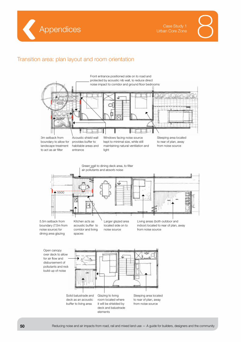
Reducing noise and air impacts from road, rail and mixed land use — A guide for builders, designers and the community50
Appendices 8Case Study 1Urban Core Zone
Transition area: plan layout and room orientation
3m setback from boundary to allow for landscape treatment to act as air filter
5.5m setback from boundary (7.5m from noise source) for dining area glazing
Open canopy over deck to allow for air flow and disbursement of pollutants and reduce build-up of noise
Acoustic shield wall provides buffer to habitable areas and entrance
Solid balustrade and deck as an acoustic buffer to living area
Windows facing noise source kept to minimal size, while still maintaining natural ventilation and light
Kitchen acts as acoustic buffer to corridor and living spaces
Glazing to living room located where it will be shielded by deck and balustrade elements
Larger glazed area located side on to noise source
Sleeping area located to rear of plan, away from noise source
Living areas (both outdoor and indoor) located to rear of plan, away from noise source
3000
4000
5500
Front entrance positioned side on to road and protected by acoustic nib wall, to reduce direct noise impact to corridor and ground floor bedrooms
Green wall to dining deck area, to filter air pollutants and absorb noise
Sleeping area located to rear of plan, away from noise source

Reducing noise and air impacts from road, rail and mixed land use — A guide for builders, designers and the community 51
Appendices8 Case Study 1Urban Core Zone
1) Tree foliage helps to capture and filter air borne pollutants and obscure views to noise source
2) Balustrade detailing to allow air flow to all areas of deck, rather than creating a ‘container’ for air pollutants
3) Solid balustrade will block direct line of sight for noise, reducing impact of noise on internal habitable spaces
4) Green wall provides textured natural material to absorb sound waves while also capturing and filtering air borne pollutants
5) Open canopy allows for clear airflow to dispel airborne pollutants from deck area and eliminates reflection of sound waves
6) Glazing to living/dining areas set back from main noise source.
1) Low height solid fencing provides acoustic buffer while still maintaining sight lines and ‘active’ facade
2) Landscape planting in front of built form and particularly beneath windows, to act as air filter
3) Acoustic shield wall integrated into design to provide a buffer to noise sources
4) Main entrance positioned oblique to noise source and sheltered by deck above
5) Larger glazed areas positioned side on to noise source
6) Smaller areas of glazing facing noise source. Where window shrouds are used for sunshading, the shroud material should either have sound absorbtive or acoustically transparent (ie; mesh or perforated material) to reduce opportunity for reflection of sound waves.
Transition area: integrated design techniques
Deck & balustrade design features
Entrance & glazing design features
1
1
2
34
5
6
2
3
4
5
6

Reducing noise and air impacts from road, rail and mixed land use — A guide for builders, designers and the community52
Appendices 8Case Study 1Urban Core Zone

Reducing noise and air impacts from road, rail and mixed land use — A guide for builders, designers and the community 53
Appendices8Case Study 2 Urban Corridor Zone (Boulevard Policy Area)

Reducing noise and air impacts from road, rail and mixed land use — A guide for builders, designers and the community54
Appendices 8Case Study 2Urban Corridor Zone (Boulevard Policy Area)
SUBJECT SITE
50m
20m
LANE
N O I S E S O U R C E
BOULEVARD
This case study focuses on a nominal infill site, with an east facing primary road frontage of 20m, and a site depth of 50m with rear lane access. The development model preferred for this site is a medium-high density mixed use building, with concealed basement and ground level carparking, showroom style ground floor retail accommodation, and a mix of 1 and 2 bedroom residential apartments above with a maximum building height adopted of 10 storeys.
The design response is based on the objectives set out in the Desired Character, Building Height, Interface Height Provisions, Design and Appearance, and Building Envelope sections of the Urban Corridor Zone, with reference to the Desired Character statement of the Boulevard Policy Area.
Controls and assumptions
Given the site constraints and new planning policy objectives, the resulting design response balances the intent of all these requirements, rather than demonstrating an ideal noise and air quality solution. The design response proposed is also one of many potential ways to deal with these issues in an integrated manner.
Rather than rely on secondary building elements such as door seals, glazing types, insulation, and mechanical ventilation systems, this case study deals with noise and air quality in the primary design elements of the building wherever possible.
In the context of this case study these are:
• building form and massing
• apartment layout and room orientation
• integrated design elements.

Reducing noise and air impacts from road, rail and mixed land use — A guide for builders, designers and the community 55
Appendices8 Case Study 2Urban Corridor Zone (Boulevard Policy Area)
Design response summary
GROUND FLOOR COMMERCIAL/RETAIL
5000 6000
1330018900
The response to the boulevard site focuses on measures to control noise and air quality, with consideration to the roadway noise source. Other broader planning principles and objectives, including natural light and ventilation, open space provision, and ‘active’ streetscape design techniques have also been considered.
1
2
3
4
56 7
8
9
Site Planning
1) The kerb and footpath combined width is approximately 5m. This width allows for planting of reasonable sized street trees, which have potential to play an important role in filtering air borne pollutants, depending on species type.
2) The building model assumes a further 6m setback, to allow for additional landscape treatment, and to increase the separation distance for habitable areas.
Apartment planning
3) Solid planters along the edge of terraces act as a barrier to noise, as well as an air filter (depending on species type).
4) Glazed balustrade treatment used selectively to capture key views from living areas, reducing balustrade area vulnerable to noise impact.
5) Corner terrace configuration increases air circulation through outdoor areas, reducing opportunity for entrapment of air borne pollutants.
6) Door ways to terrace from living area located oblique to road noise source.
7) Bedroom located further away from noise source, of sufficient distance to eliminate direct facade exposure to noise source.
8) Second bedroom located to rear of plan. Windows from both bedrooms positioned side on to noise source and at the furthest point possible from the noise source.
9) In this design, placing solid planters on the building’s front edge serves to shield living areas from direct exposure to noise from below.
The following features of the design focus specifically on improving noise and air outcomes.

Reducing noise and air impacts from road, rail and mixed land use — A guide for builders, designers and the community56
Appendices 8Case Study 2Urban Corridor Zone (Boulevard Policy Area)
Design response - typical apartment plan and balcony section diagram
Use glass balustrade in selected locations where parkland view is important
Opening doors to living area oriented side on to the traffic noise
Open plan living spaces protected by planter and terrace
Bedroom located further back from the noise source
A L
L O
W
V I E
W
P R O T E C T
5 metres
2.3 metres Bedroom located further back from the noise source. Operable side window located towards the back of the room and side on to the traffic noise
Corner terraces allow for cross ventilation and dispersion of air
Solid planter along balcony edge acts as a partial noise baffle and air filter
1) Glass balustrade used in selective location to capitalise on views
2) Solid planter along balcony edge acts as noise barrier
3) Corner terrace allows for air movement and dispersion of air borne pollutants.
4) Opening doors to living area oriented side on to the traffic noise
5) Bedroom set back further from noise source and uses to reduce or eliminate direct facade contact with noise source.
1
2
3
4
5

Reducing noise and air impacts from road, rail and mixed land use — A guide for builders, designers and the community 57
Appendices8 Case Study 2Urban Corridor Zone (Boulevard Policy Area)
Design response - alternative treatments - larger sites
1
2
3
On larger or consolidated sites it may be possible to achieve the following measures to further control air and noise quality:
1) Increased set back of residential apartment tower to increase separation distance from noise source
2) Increased setback also allows for more extensive open space provision, including tree planting for air filtering
3) Two storey podium with commercial or shared resident facilities on second floor increases separation distance for residential dwellings.

Reducing noise and air impacts from road, rail and mixed land use — A guide for builders, designers and the community58
Appendices 8Case Study 1Urban Core Zone

Reducing noise and air impacts from road, rail and mixed land use — A guide for builders, designers and the community 59
Appendices8Case Study 3 Urban Corridor Zone (High Street Policy Area)

Reducing noise and air impacts from road, rail and mixed land use — A guide for builders, designers and the community60
Appendices 8Case Study 3Urban Corridor Zone (Highstreet Policy Area)
SUBJECT SITE
44m
20m
SECONDARY ROAD
SECONDARY ROAD
HIG
H S
TREE
TN
O I
S E
S
O U
R C
E
For the High Street Policy Area Case Study, the nominal infill site has an east facing primary road frontage of 20m, and a site depth of 44m with rear lane access. The development model preferred for this site is a medium-high density mixed use building, with concealed basement and ground level carparking, shop style ground floor retail accommodation, and a mix of 1 and 2 bedroom residential apartments above with a maximum building height of 6 storeys.
The design response is based on the objectives set out in the Desired Character, Building Height, Interface Height Provisions, Design and Appearance, and Building Envelope sections of the Urban Corridor Zone, with reference to the Desired Character statement of the High Street Policy Area.
Given the site constraints and new planning policy objectives, the design response balances the intent of all these requirements, rather than demonstrates an ideal noise and air quality solution. The design response proposed is also one of many potential ways to deal with these issues in an integrated manner.
Rather than rely on secondary building elements such as door seals, glazing types, insulation, and mechanical ventilation systems, in this design exercise we have attempted to deal with noise and air quality in the primary design elements of the building wherever possible.
In the context of this case study these are:
• Building form and massing
• Apartment layout and room orientation
• Integrated design elements.
Controls and assumptions

Reducing noise and air impacts from road, rail and mixed land use — A guide for builders, designers and the community 61
Appendices8 Case Study 3Urban Corridor Zone (Highstreet Policy Area)
Side orientation
To assist in noise and air quality control, the apartments were initially turned away from the traffic and towards the north by creating a 5m wide light well that ran continuously from the street frontage, all the way to the rear of the site. By doing this, a much smaller number of apartments faced the road, and greater separation distance could be achieved.
Despite assisting with noise and ventilation, this design response did not sufficiently address the street, and created a development that relied on neighbouring buildings remaining low scale and undeveloped.
Street & side orientation
This design response oriented apartments away from the street, but also provided apartments facing the street that would rely on acoustic treatment to maintain internal amenity.
Again, this response did not fully address the street, and could create a weak streetscape if adopted by adjacent sites.
Full street orientation
The adopted site planning design response looked to maintain the street-wall approach as preferred in the planning policy modules. The full width of the site was utilised to provide aspect and view to three street facing apartments, while the remaining three apartments on each floor would face the rear of the site.
In this design response, facade articulation, protruding building elements, corner terraces, setback upper floors, apartment layout, room orientation, window location and screen and balustrade details will assist in protecting internal spaces from noise and air pollutants.
Design response - option studies
Side orientation
Street & side orientation
Full street orientation

Reducing noise and air impacts from road, rail and mixed land use — A guide for builders, designers and the community62
Appendices 8Case Study 3Urban Corridor Zone (Highstreet Policy Area)
Articulated building form creates additional noise shields
Corner terraces assist with cross ventilation until development occurs on adjacent land
Deep corner terraces create additional separation distance between the traffic and internal spaces, while providing usable outdoor space.
Design response - plan diagrams
Typical floor layout
Communal private open space can be located at the rear of the development, away from the traffic noise and air pollutants.
Apartment layout and design assists with noise and air quality control. Refer to the typical plan below.

Reducing noise and air impacts from road, rail and mixed land use — A guide for builders, designers and the community 63
Appendices8 Case Study 3Urban Corridor Zone (Highstreet Policy Area)
Design response - plan diagrams
Full street orientationSolid balustrade helps to shield and deflect noise away from habitable rooms and private open spaces
Optional 2nd bedroom window positioned behind screen. Can remain closed, while allowing natural ventilation through primary window.
Typical apartment layout
4m 1m2.8m 3m
LIVINGDININGKITCHEN BED
TERRACE
BED
BTH
ENS
Horizontal screening for visual protection and sun shading can provide some sound reduction if operable and sealed
Primary operable second bedroom window, located further back from noise source, and side-on to the traffic.
Window to master bedroom located further away from noise source.
Living room external doors located side-on to the dominant noise source, assisting to reduce noise impact and air pollutants.
Additional setback zone to protect internal apartment spaces, and can include landscaping.

Reducing noise and air impacts from road, rail and mixed land use — A guide for builders, designers and the community64
Appendices 8Case Study 3Urban Corridor Zone (Highstreet Policy Area)
Design response - plan diagrams
Breeze and ventilation of upper level open spaces creates air movement and dispersion of air pollutants.
Potential roof garden spaces setback from the street boundary and creates shield from direct traffic noise.
Distance setback to upper levels removes the line of sight to the traffic.
Roof garden plan

Reducing noise and air impacts from road, rail and mixed land use — A guide for builders, designers and the community 65
Appendices8 Case Study 3Urban Corridor Zone (Highstreet Policy Area)
Design response - overall section diagrams
These section diagrams demonstrate how simple building form, massing and integrated elements can assist in noise and air quality control, while still providing other benefits to the development.
1
1
2
5
2
3
4
55
6
1) In addition to rain and sun shelter the street canopy provides a noise shield and reduces the degree of direct traffic noise to the level 1 apartments.
2) The separation distance between the noise source and habitable spaces increases as building height increases, and protruding building elements help to protect internal rooms.
3) Solid balustrading can help to shield and deflect some noise away from habitable spaces and private open spaces, and when incorporated with plants and vegetation, can soften the impact of noise and air pollutants.
4) Horizontal screening if operable and sealed, can be incorporated for some noise control and sun shading to protect windows facing the street. By screening the view of traffic, the visual separation can also help reduce the perceived impact.
5) With additional set back distances provided at upper levels, the edge of the built form below serves as a noise shield, and can reduce or eliminate the direct line of sight between the noise source and habitable room facades.
6) Depending on the orientation, communal private open spaces can be located at the rear of the development, away from the traffic noise and air pollutants, while still receiving good access to direct sunlight.

Reducing noise and air impacts from road, rail and mixed land use — A guide for builders, designers and the community66
Appendices 8Case Study 3Urban Corridor Zone (Highstreet Policy Area)
Visual separation from noise source with operable and sealed horizontal screening.
Protruding balconies shield habitable rooms and upper levels from the noise source.
Solid balustrade helps to shield and deflect noise away from habitable rooms and private open spaces.
Solid balustrade down stand adds to the shielding effect, and can assist with building shading.
Potential solid planter along balcony edge to act as a noise baffle and air filter.
Balcony soffits lined with acoustic panels to absorb sound and reduce sound reflection.
Operable bedroom window located further back from noise source, and oriented side-on to the traffic. Awning located at low level to increase the noise shielding potential of the protruding balconies.
Living room located further back from the noise source.
Habitable room facade set back from street boundary to incorporate wrap-around balcony with additional buffer to traffic noise.
Design response - balcony section diagram
This section diagram is indicative of how the design of the balcony and apartment window locations can reduce the impact of traffic noise and associated air pollutants.
Sound can be absorbed with acoustic treatment to soffits and wall linings, to reduce the amount of reflected noise.
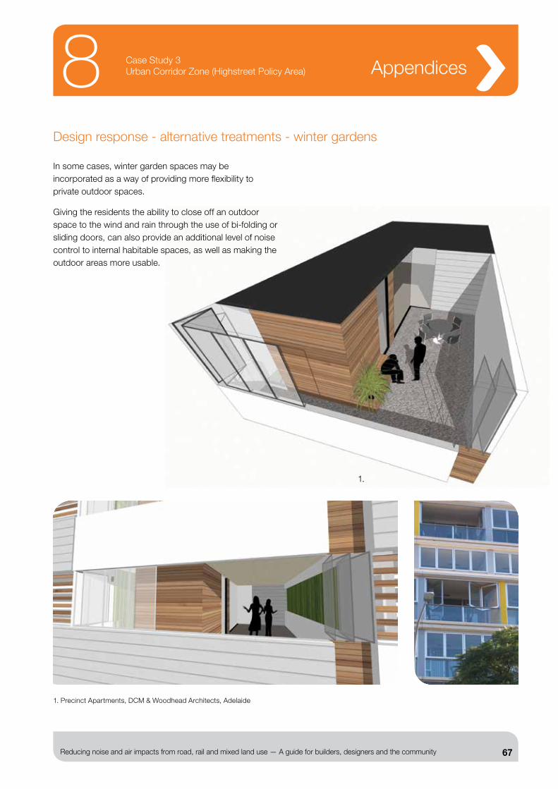
Reducing noise and air impacts from road, rail and mixed land use — A guide for builders, designers and the community 67
Appendices8 Case Study 3Urban Corridor Zone (Highstreet Policy Area)
Design response - alternative treatments - winter gardens
In some cases, winter garden spaces may be incorporated as a way of providing more flexibility to private outdoor spaces.
Giving the residents the ability to close off an outdoor space to the wind and rain through the use of bi-folding or sliding doors, can also provide an additional level of noise control to internal habitable spaces, as well as making the outdoor areas more usable.
1.
1. Precinct Apartments, DCM & Woodhead Architects, Adelaide

Reducing noise and air impacts from road, rail and mixed land use — A guide for builders, designers and the community68
Appendices 8Case Study 1Urban Core Zone
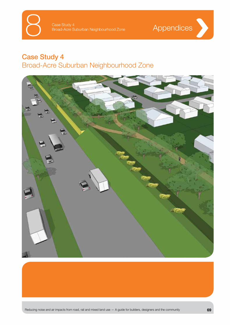
Reducing noise and air impacts from road, rail and mixed land use — A guide for builders, designers and the community 69
Appendices8 Case Study 4Broad-Acre Suburban Neighbourhood Zone
Case Study 4 Broad-Acre Suburban Neighbourhood Zone

Reducing noise and air impacts from road, rail and mixed land use — A guide for builders, designers and the community70
Appendices 8Case Study 4Broad-Acre Suburban Neighbourhood Zone
RESIDENTIAL AREA
NO
ISE
SO
UR
CE
EX
PR
ES
SW
AY
SECONDARY ROAD
SECONDARY ROADGREENWAY & SEPARATION
EARTH MOUND
NOISE WALL
130m-200m
Design RequirementsThis case study focuses on a hypothetical low density broad-acre residential site, adjacent to an expressway.
The combination of high vehicle speed and large traffic volumes produces significant noise and air emissions, and is of particular concern for dwellings located close to the roadway.
This case study illustrates techniques for acoustic treatments other than the deemed-to-satisfy construction provisions in the Minister’s Specification SA 78B.
Where relevant, the design response also adopts the objectives and desired development character of the Suburban Neighbourhood Zone.
Controls and AssumptionsIn this design exercise, the assumed existing conditions include:
• a high-speed road (as the noise and air emissions source) in close proximity to a residential zone (within 130m)
• all other noise mitigation measures, such as road surfacing, gradients, and traffic management have already been considered.
Ways of dealing with noise and air quality at, or near to the source, with a range of physical barriers:
• noise walls
• earth mounds
• greenways and increased separation distance.
As demonstrated, a combination of these treatments can be applied on any given broad-acre site.

Reducing noise and air impacts from road, rail and mixed land use — A guide for builders, designers and the community 71
Appendices8 Case Study 4Broad-Acre Suburban Neighbourhood Zone
Design opportunities to control noise and air quality
1. Roadside Noise Walls
Roadside noise barriers or walls are physical barriers between the noise source and the adjacent residential development.
Due to their size and length, their impact from both the road-side and the residential side can be significant, and should be considered in the design of the wall.
A number of design treatments can reduce the visual impact of a wall, for example:
• varying the height along the wall length to break down the scale
• articulating the barriers along their length to provide relief and visual interest
• using different materials and textures, either in the profile of the wall, or changing the material in wall sections
• integrating with other barriers, such as earth mounds, landscaping, to make use of the natural topography
• incorporating transparent sections to visually connect the viewer to the wider landscape.
2. Earth Mounds
Earth mounds, an alternative to roadside noise walls, use the landscape as a barrier, and in many cases can use the natural topography to provide complete or partial screening of road noise.
Earth mounds can:
• take additional planting to reduce the perceived bulk and height of the barrier, assist with air pollutant reductions and provide a perceived softening of road noise
• use the natural topography, eg road cuttings
• offer a more cost effective solution to mitigating road noise
• when used in conjunction with noise walls, reduce the visual impact on the viewer.
1. Gallipoli Underpass, Hassel, Adelaide 2. Eastlink, Wood/Marsh, Victoria 3. Bio Barrier, Benz Kotzen, Netherlands 4. Southern Expressway, Adelaide - artist impression
1.
2.
3.
4.
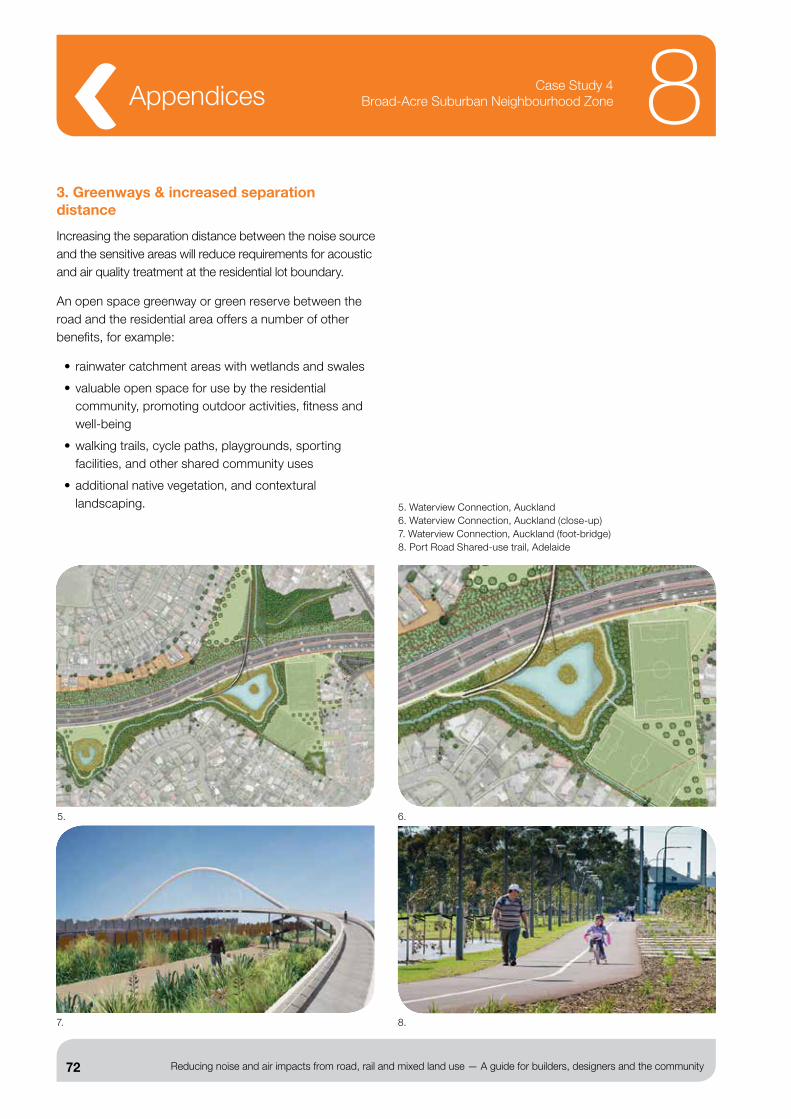
Reducing noise and air impacts from road, rail and mixed land use — A guide for builders, designers and the community72
Appendices 8Case Study 4Broad-Acre Suburban Neighbourhood Zone
3. Greenways & increased separation distance
Increasing the separation distance between the noise source and the sensitive areas will reduce requirements for acoustic and air quality treatment at the residential lot boundary.
An open space greenway or green reserve between the road and the residential area offers a number of other benefits, for example:
• rainwater catchment areas with wetlands and swales
• valuable open space for use by the residential community, promoting outdoor activities, fitness and well-being
• walking trails, cycle paths, playgrounds, sporting facilities, and other shared community uses
• additional native vegetation, and contextural landscaping. 5. Waterview Connection, Auckland
6. Waterview Connection, Auckland (close-up) 7. Waterview Connection, Auckland (foot-bridge) 8. Port Road Shared-use trail, Adelaide
5. 6.
8.7.
7.

Reducing noise and air impacts from road, rail and mixed land use — A guide for builders, designers and the community 73
Appendices8 Case Study 4Broad-Acre Suburban Neighbourhood Zone
Design response - Introduction
This case study explores three different primary methods of protecting a nominal residential subdivision from vehicle noise and air pollutants from a high-speed expressway: noise walls, earth mounds and greenways.
The site incorporates a small section all three of these methods, with overlapping zones that form hybrid methods. Along any given stretch of road or expressway, all three solutions may be possible.
Noise walls are a common way of providing measurable acoustic protection, and can also provide some degree of separation from roadside air pollutants. They can be designed to respond to specific acoustic requirements, the natural setting and the identity of the area they are protecting.
Earth mounds as a method of screening noise are also effective but are generally found in locations where the natural topography is suitable. They may also be a cost effective solution if excess fill on the site can be used. They do take up more land than the same height noise wall, and can still be expensive to create on flat sites. For these reasons, earth mounds would not generally be adopted as the only physical barrier on this type of site, but rather would form part of the base of a constructed wall structure.
The first two methods provides a physical barrier to the noise, and effectively eliminates the need for specific acoustic treatment of the sensitive areas. With the road noise taken care of in the wall or mounding, residences and private outdoor spaces are protected, and there is little or no need to develop any further design techniques or strategies for controlling sound.
In this situation, the emphasis is on the design of the wall itself, and in developing ways to successfully integrate this element within the surrounding landscape.
The third method adopts a greater separation distance between the road noise and the residences by adopting a greenway or green reserve.
While the separation distance adopted is not enough to reduce the residence to the lowest sound exposure category, it allows exploration of ways to deal with more manageable noise levels in the mid-range sound exposure categories.
The following pages highlight ideas, thoughts and concepts for each of the three identified methods for controlling sound and air quality in a Suburban Neighbourhood Zone alongside a high-speed expressway.
GREENWAY & SEPARATION EARTH MOUNDNOISE WALL

Reducing noise and air impacts from road, rail and mixed land use — A guide for builders, designers and the community74
Appendices 8Case Study 4Broad-Acre Suburban Neighbourhood Zone
Noise walls & earth mounds
Of the numerous examples of high quality design solutions for roadside noise walls, this case study provides examples of some of the key themes in the design of these walls, including:
• Scale: consideration of the perceived size and impact of the wall from both the road side and the residential side.
• Height: altering the height can break the continuous horizontality of the wall, and can accommodate changes in topography and differing building heights on the sensitive side of the wall; micro-climate issues such as overshadowing and air movement should also be taken into account.
• Articulation: applying steps, recessed and profiles in the wall to provide visual interest and relief.
• Materials: The use of different materials, and the effect of texture and finish.
• Landscape Integration: Integrating landscape treatments into the wall design, and partial use of earth mounds.
LINE OF SIGHT
DIFFRACTED SOUND
NOISE SOURCE
A simple solid wall element protects from road noise, but presents as a large physical barrier to viewers on both sides
The introduction of mounding and groundcover can soften the impact and reduce the perceived size of the wall
Taking this concept further, additional mounding and taller planting can also assist with the dispersion of air pollutants, and can provide a perceived softening of the traffic impact.
Wall height needs to take into account taller residential buildings where practical.
Scale

Reducing noise and air impacts from road, rail and mixed land use — A guide for builders, designers and the community 75
Appendices8 Case Study 4Broad-Acre Suburban Neighbourhood Zone
1. Oxidised Steel sound wall from Peninsula Link website www.peninsulalink.com.au 2. Deer Park sound wall image from Ausgroup Alliance website www. ausplastics.com.au
Varied wall height for visual interest
Step in wall height relating to changes in topography or taller residential buildings behind
Articulated wall panels with solid recessed returns
Deep profiled solid wall panels casting shadow
Step in wall height to break up long horizontal elements
2.1.
Height Articulation

Reducing noise and air impacts from road, rail and mixed land use — A guide for builders, designers and the community76
Appendices 8Case Study 4Broad-Acre Suburban Neighbourhood Zone
3. East Link sound wall image from Ausgroup Alliance website www. ausplastics.com.au 4. Wall image from Urban Design Principles document by NZ Transport Agency
Materials Landscape and earth mound integration
Example elevational treatments using a mixture of materials, textures and finishes provides opportunity for visual interest and contextural association.
The application of low height planting with utilisation of natural topography reduces the height and impact of the wall
Smaller earth mound with ground cover planting and trees conceals the wall
Partial mounding combined with complete cover of wall element with vegetation
4.3.

Reducing noise and air impacts from road, rail and mixed land use — A guide for builders, designers and the community 77
Appendices8 Case Study 4Broad-Acre Suburban Neighbourhood Zone
Greenways and implications of increased separation distances
The provision of greater separation distance between the road and the residences through the incorporation of an open space – a greenway, reserve or parkland area, offers an opportunity to protect from noise at the residential lot boundary and the built form edges of the residence itself, while also providing a valuable amenity to the residents of the local community.
The diagram below indicates how separation distance affects the sound exposure category. Refer to the Ministers Specification SA 78B for more information regarding sound exposure categories.
<15MCategory
5
15-35MCategory
4
35-60MCategory
3
60-130MCategory
2
130-200MCategory
1

Reducing noise and air impacts from road, rail and mixed land use — A guide for builders, designers and the community78
Appendices 8Case Study 4Broad-Acre Suburban Neighbourhood Zone
60m greenway area
Sound exposure Category 2
Increased separation distance = reduced acoustic performance requirements of the dwelling
Using the principle set out in the diagram below, the benefit of adopting greenway alongside the roadway is evident.
While a separation distance in the order of 200m will bring the sound exposure category down to its lowest level, this is unlikely to be easily achieved within the context of a residential subdivision - ie maximising the land available to create new housing.
The adopted mid-range distance of 60m may be more realistically achievable. Its implications for the design and construction of the residential buildings, and lot boundary fencing have been taken into account.
1. Port Road Greenway, Adelaide
1.

Reducing noise and air impacts from road, rail and mixed land use — A guide for builders, designers and the community 79
Appendices8 Case Study 4Broad-Acre Suburban Neighbourhood Zone
With an increased separation distance, noise and air quality can be further managed in a Suburban Neighbourhood Zone by for example:
• providing solid acoustic fencing to the lot boundary facing the noise source, wrapping around to the boundaries perpendicular to the noise source
• articulating the building form to create noise shields between other areas of the building allowing cross ventilation, air movement and breezes to move polluted air away from openable windows and outdoor spaces
• avoiding orientating external doors and operable windows face-on to the noise source where practical
• configuring plan layouts so that external doors and openable windows are located as far as possible from potential sources of noise and air pollution
Design opportunities to control noise and air
Quality lot boundary and residence
• locating bedrooms and other habitable rooms away from the noise source, and provide buffers such as vegetation to help filter the air
• considering corner windows that allow cross ventilation
• providing dense landscaping along the lot boundaries facing the noise source which also makes an aesthetically appealing visual filter between building occupants and the road.