Embed Size (px)
Citation preview

Reducing Helium Costs more than 10-fold with the PCT Gas Saver mode
This note describes a technique for minimizing helium carrier flow when the GC-MSsystem is not in use. Helium has become expensive and costs of operation arealways a concern. Using the G1472A Rapid & Universal GC-MS Backflushing kit inthe Pressure Controlled Tee (PCT) configuration, total helium use can be lowered to< 3 mL/min while the GC-MS is dormant. The MS analyzer is still under vacuum, atoperating temperatures and can be rapidly called into use. Total helium savings overthe course of a month or year are substantial using this mode.
Introduction
Recently the price of helium carrier for gas chromatography has dramaticallyincreased and supply has become limited. Many instrument users have becomeconcerned about saving this gas whenever possible. Saving helium carrier by cool-ing and venting GC-MS instruments (single quadrupole and triple quadrupole) is notan efficient approach because air and water enter the vacuum manifold. Althoughthe instruments can rapidly reach analyzer operating temperatures, the removal ofchemisorbed water is a slow process; therefore the time necessary to reach stableoperation is lost analytical time. In addition, the frequent venting and pumpdowncycles wear out the pump system components and tend to be time consuming. Theoptimum situation has always been to keep an MS system under vacuum and attemperature to allow the system background to continuously improve or at leastremain stable. This philosophy is also true for other GC detectors. Employing GCinstrument parameters to minimize gas use, such as standby methods using lowsplit ratios with low column flows and septum purge settings, risk air intrusion withconsequent damage to the inlet or column. These methods can produce a gasusage rate of about 7 to 10 mL/min at best. While this is lower than the typical useof greater than 24 mL/min during operations, it still represents a substantial quantity of helium expended that is not available for analysis.
This note describes a state of the GC instrument enabled by the Pressure ControlledTee (PCT) and the Agilent Rapid Universal GC/MS Backflushing Kit (G1472A) inwhich total helium carrier gas use is < 3 mL/min during the archived state of theGC-MS instrument. This state is referred to as the “PCT Gas Saver mode” and,while saving helium, the MS system remains under vacuum and at temperature andrapidly can be brought into operation. In terms of helium carrier savings, nearlyevery hour the instrument is placed in this PCT Gas Saver mode is equal to a saved
Technical Overview
Harry Prest

2
hour of analysis when compared to typical (default) operating conditions (24 mL/min). Over the course of a year this can result in considerable helium gassavings. For example, archiving a GC-MS instrument with the PCT Gas Saverthrough every weekend in a year will result in a helium savings equivalent to morethan an additional 100 days or almost half of year of analytical operating time. Thistechnical overview contains specific directions for enabling this PCT Gas Savermode for PCT with the GC-MS. The approach can be easily generalized to other PCTconfigurations to enable carrier gas savings on all GC systems.
Why the PCT for GC/MS Operation?
A simple schematic and an illustration of the PCT configuration are shown inFigures 1 and 2. The analytical capillary column is split into two sections by a tee,called the Purged Ultimate Union. Many configurations of the PCT are possiblebecause the column sections do not need to be of equal lengths. Using the PCTimproves GC-MS operation by providing rapid backflushing and rapid GC servicing.
Rapid backflushing removes late eluting matrix contaminants to:
• Avoid fouling the MS source thereby increasing instrument uptime and eliminat-ing frequent source cleaning
• Avoid carryover, baseline rise, and compound retention time shifts over thecourse of sample sequences
The PCT enables both post acquisition or Post Run backflushing and Concurrentbackflushing modes to minimize run time and cycle time. Concurrent backflushingtakes place while sample data acquisition is still underway.
Rapid servicing without venting the MS system allows:
• Quick capillary analytical column cutbacks to quickly restore chromatographicperformance
• Fast inlet maintenance including liner change and septum change
• Simple column servicing or the more efficient approach of guard or coated precolumn exchange to restore compound chromatographic performance andmaintain compound retention times
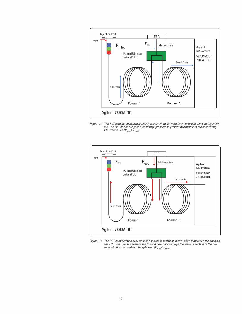
PCT operation is simple to understand (Figure 1). During GC analysis, the pressureapplied at the Purged Ultimate Union (Pepc) is just a little higher than that needed toprevent backflow into the electronic pneumatic control (EPC) module. After the GC-MS analysis is completed, the pressure is raised at the tee (Purged Ultimate Union)and lowered in the front section of column to push matrix out the split vent. This isPost Run backflushing mode. In Concurrent backflushing mode, after the last ana-lyte of interest has passed through the front column and the tee (Purged UltimateUnion) and entered the second section of column, the head pressure at the inletcan be dropped (Pinlet) so that the later eluting components will begin to retreat incolumn 1. The last analytes then proceed to column 2 and enter the MS detector.The MS system can be any of the Agilent systems including diffusion pumped sys-tems.
Details and evidence of PCT performance are given in several application notes [1-4] and instructions for the installation and operation are given in the AgilentG1472A Rapid Universal GC/MS Backflushing Kit Pressure Controlled Tee manual(G1472-90001).
For simplicity, this note describes work performed with the midpoint PCT configura-tion in which the Purged Ultimate Union is inserted between two 15-m columns(0.25-mm id). The concept is easily generalized to other column arrangements.
3
Vent
EPC
Column 1 Column 2
Purged Ultimate Union (PUU)
Agilent MS System
5975C MSD7000A QQQ
Agilent 7890A GC
Injection Port
Z mL/min
Z+ mL/min
Pepc Makeup linePinlet
Figure 1A. The PCT configuration schematically shown in the forward flow mode operating during analy-sis. The EPC device supplies just enough pressure to prevent backflow into the connectingEPC device line (Pinlet> Pepc).
Vent
EPC
Column 1 Column 2
Purged Ultimate Union (PUU)
Agilent MS System
5975C MSD7000A QQQ
Agilent 7890A GC
Injection Port
-x mL/min
X mL/min
Makeup linePepcPinlet
Figure 1B. The PCT configuration schematically shown in backflush mode. After completing the analysisthe EPC pressure has been raised to send flow back through the forward section of the col-umn into the inlet and out the split vent (Pinlet< Pepc).

4
Procedure for PCT Gas Saver Mode
To put the system in PCT Gas Saver mode:
1. Set the injection port temperature to OFF and allow it to cool to room temperature. The port will cool faster with the GC oven set to 20 °C. After the oven has reached room temperature it can be turned OFF to savepower.
2. Set the Column 2 flow to 1.5 mL/min (constant flow) (Figure 3). (Note: for columns narrower than the 0.25 mm id used in this example,set the pressure at Column 2 to 3 psi. For example, a 10 m × 0.18 mm idColumn 2 would only require a flow of ~0.6 mL/min which results in evenhigher gas savings.)
Figure 2. Picture of an installed PCT: Column 1 connects (dash-dot-dash) the injection port to thePurged Ultimate Union (at right) and Column 2 connects (dash) the MS system to the PurgedUltimate Union.
Figure 3. Column 2 (AUX →MSD) conditions: column flow setpoint 1.5 mL/min.

5
4. In this 15 m × 15 m column configuration, the calculated flow displayed on theGC panel for Column 1 near the inlet should be negative and approximately −0.53 mL/min (Figure 5). This shows column flow is back from the PurgedUltimate Union into the inlet.
3. When the injection port and oven have cooled, set the inlet pressure to OFF. Theport must then be opened by either removing the septum and septum nut orrotating the twist-top to release the liner connection (Figure 4). This releasesthe pressure inside the port and the inlet. The Column 1 display should read zeroor close to it. (Alternatively, if the user does not want to open the injection port, then:set the 7890 Gas Saver to OFF, the inlet pressure to 0, total flow to 0 and septumpurge to 0. The 7890 system will beep as it can not achieve the setpoints.)
Figure 4. When the injection port is cold, loosen the injection twist-top by counter-clockwise rotationof the yellow handle. Make sure to lift the top slightly to insure the seal is broken.
Figure 5. Column 1 (Inlet → Aux) conditions: pressure OFF, the flow calculation result is shown andthe negative sign indicates flow is back into the injection port.
6
To return the system back to use:
1. Set the Column 2 flow to 3 mL/min, for diffusion pump systems, or 8 mL/min forturbo systems. See the PCT User’s Manual
2. Reseal the injection port and set the inlet pressure to 2 psi.
3. Set the septum purge to ON at ≥3 mL/min and gas saver on with a split flow of≥20 mL/min.
4. Turn on the injection port temperature.
The Column 1 flow will be negative (−1.7 mL/min in 15 m × 0.25 mm id configura-tion) and as the port warms up to operating temperature, contaminants accumulat-ed during the idle period will be backflushed out the split vent and not transferredinto the analytical column.
Results
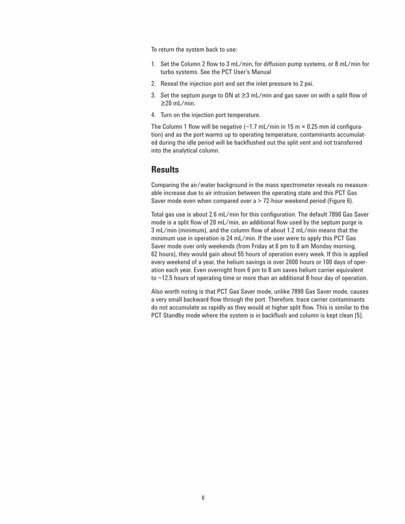
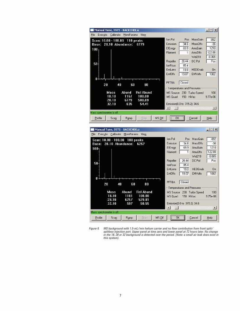
Comparing the air/water background in the mass spectrometer reveals no measure-able increase due to air intrusion between the operating state and this PCT GasSaver mode even when compared over a > 72-hour weekend period (Figure 6).
Total gas use is about 2.6 mL/min for this configuration. The default 7890 Gas Savermode is a split flow of 20 mL/min, an additional flow used by the septum purge is 3 mL/min (minimum), and the column flow of about 1.2 mL/min means that theminimum use in operation is 24 mL/min. If the user were to apply this PCT GasSaver mode over only weekends (from Friday at 6 pm to 8 am Monday morning, 62 hours), they would gain about 55 hours of operation every week. If this is appliedevery weekend of a year, the helium savings is over 2600 hours or 100 days of oper-ation each year. Even overnight from 6 pm to 8 am saves helium carrier equivalentto ~12.5 hours of operating time or more than an additional 8-hour day of operation.
Also worth noting is that PCT Gas Saver mode, unlike 7890 Gas Saver mode, causesa very small backward flow through the port. Therefore, trace carrier contaminantsdo not accumulate as rapidly as they would at higher split flow. This is similar to thePCT Standby mode where the system is in backflush and column is kept clean [5].
7
Figure 6. MS background with 1.5-mL/min helium carrier and no flow contribution from front split/splitless injection port. Upper panel at time zero and lower panel at 72 hours later. No changein the 18, 28 or 32 background is detected over the period. (Note: a small air leak does exist inthis system).

8
Conclusions
The PCT configuration provides a number of features that improve GC-MS operation.These include rapid backflushing to protect the column and MS source and increaseproductivity, and quick, ventless servicing of the column and inlet to maintain dataquality. The PCT Gas Saver mode is an additional capability which “archives” theGC-MS system with extremely low helium carrier gas use. This allows the MS ana-lyzer to remain at temperatures where the background and stability of the systemimproves, or maintains its integrity. The GC system can be quickly called into use sothere is less time required than in venting the system and returning it to service.
PCT Gas Saving Mode uses carrier at < 3 mL/min. When compared to typical GC-MS use, every hour the system is in PCT Gas Saver Mode is an additional hour ofanalytical time and carrier saved. Routinely archiving the system in this mode forevery weekend of a year equates to more than 100 days of analytical time recovered.Since the PCT can be enabled on any GC-MS (or GC) system, an entire laboratorycan employ these savings to dramatically reduce one of the major costs of opera-tion. Table 1 shows a summary of the additional analytical time that can be providedby PCT Gas Saver mode over various durations.
Table 1. Additional Operating Analytical Time (Days) Supplied by the PCT Gas Saver Mode as aFunction of the Duration Applied and Period of Consistent Use.
PCT Gas Saver Mode Use
Period Every night Only weekends Evening and weekends
1 Week 3.6 days 2.3 days 4.4 days1 Month 14.6 days 9.2 days 17.5 days1 Year 174.6 days 110.5 days 210.3 days
Note: For example, using PCT Gas Saver Mode only on the weekends will add an additional 110 days/year of operationcompared to the default Gas Savers Settings of 20 mL/min (plus column and septum flows of 1.2 mL/min and 3 mL/min, respectively).

9
References
1. “Capillary Flow Technology for GC/MS: A Simple Tee Configuration for Analysisat Trace Concentrations with Rapid Backflushing for Matrix Elimination,” Agilent Technologies publication (5989-8664EN)
2. “Capillary Flow Technology for GC/MS: Efficacy of the Simple Tee Configurationfor Robust Analysis Using Rapid Backflushing for Matrix Elimination,” AgilentTechnologies publication (5989-9359EN)
3. “Maintaining Compound Retention Times with the Backflush enabled PressureControlled Tee Configuration for Agilent 7890A GCs with Agilent 5975 SeriesMSD and Agilent 7000 Series Triple Quadrupole MS Systems,” AgilentTechnologies publication (5990-4643EN)
4. “Implementation of the Pressure Controlled Tee for Backflushing for the 7000Series Triple Quadrupole Mass Spectrometer: Implications for Sensitivity,”Agilent Technologies publication (5990-4504EN)
5. “User Quick Guide to Pressure Controlled Tee (PCT) Operation - Post RunBackflushing,” Agilent Technologies publication (5990-5484EN)
Acknowledgements
The author is grateful for many helpful discussions with Bruce Quimby and Bob Henderson at Agilent Technologies, Wilmington, DE.
For More Information
For more information on our products and services, visit our Web site at www.agilent.com/chem.

www.agilent.com/chem
Agilent shall not be liable for errors contained herein or for incidental or consequential dam-ages in connection with the furnishing, performance, or use of this material.
Information, descriptions, and specifications in this publication are subject to change with-out notice.
© Agilent Technologies, Inc., 2010Printed in the USAApril 1, 20105990-5444EN