Embed Size (px)
Citation preview
Honeywell Sensing and Control 1
Reduced Package Size for Medical Flow Sensor
R. W. Gehman, M. G. Murray, and J. W. Speldrich
Honeywell Freeport, IL 61032
Previously Presented at the IMAPS Technical Symposium May 3, 2000
Abstract
How does one get 500 liters per minute (LPM) into a 0.05-liter bag? This paper will discuss how to achieve the aggressive medical market requirements for a family of flow sensors and how to reconcile these requirements with thermal to electronic silicon based microstructure sensor technology. Goals for this device include: minimal power consumption, fast response time, minimal pressure drop at full scale, minimal repeatability and hysteresis errors, and, above all, small package size. In developing the Honeywell prototype, the greatest challenge that was overcome was the tradeoff between high flow rates and small size. The flow must be kept laminar within the entire operating range. This paper will discuss the technology chosen, the history of the technology in this market, the analysis, modeling and experimentation that proved a viable concept and the initial product development that resulted from these efforts. Key Words: sensors, airflow, turbulence, laminar, miniature INTRODUCTION
Today, we live in a technologically digitized world where controls and control systems are fundamental to every aspect of life. The fundamental building blocks of any control system include: a decision making device, an actuator to implement the decision, a series of sensors to provide information about current conditions and trends within the system, and a communications network that links to the other system components. Honeywell’s expertise is in the design and manufacture of microelectronic thermal sensors used to sense the mass flow of air.
HISTORY
Historically, the direct measurement of mass airflow has been performed by mechanical means in which precision was less important. When precision was system critical, the measurement was made indirectly by calculating flow from precision sensor measurements of temperature, differential pressure, and absolute pressure. The development of hot wire anemometers allowed highly accurate direct measurement of mass airflow. This technique is very sensitive, fast, and highly repeatable with very low hysteresis. Direct measurement of mass airflow is limited by the need for higher power consumption, lower accuracy near zero flow, larger device size than most pressure sensors and, in the past, questionable
long term stability. This technology continues to advance.
RECENT TECHNOLOGY ADVANCES
In the early 1980s, the development of a derivative of micromachined silicon technology and hot wire sensing methods addressed the limitations of other flow sensing techniques. Figure 1, below, shows the sensor chip and its configuration.
Figure 1. Airflow Sensing Chip The sensing and heating circuits were separated and the sensor output was designed as a difference of two
Honeywell Sensing and Control 2
temperature sensors, one on each side of the heater (upstream and downstream). The heater and sensors consist of a thin film of high TCR (Temperature Coefficient of Resistance) platinum deposited between two layers of silicon nitride passivation. Holes are cut through the passivation and silicon is anisotropically etched from under the Si3N4 to form two bridges. Each bridge includes one temperature sensor and ½ of the heater. In addition, each bridge is randomly designated as either upstream or downstream and is approximately 150 ∝ m square. The heater is set to draw power until the temperature [of the bridge] reaches 160°C above ambient temperature. Under zero flow, the two temperature sensors have the same output, giving a zero voltage difference. When flow is applied, the upstream sensor cools down and the downstream sensor heats up giving a voltage difference proportional to mass flow. The sign of the voltage difference (plus or minus) indicates the direction of the flow.
SENSOR CHARACTERISTICS
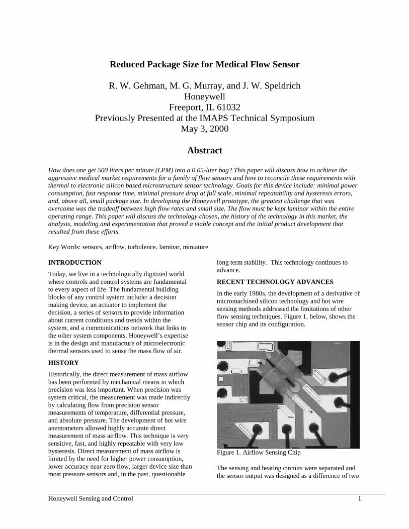
Because of the sensor’s small size, extremely low thermal mass, and large temperature gradients, the sensor is inherently very fast (about 1 ms), has high repeatability, and low hysteresis. Because the sensor is ratiometric, with a proportional method of sensing, the device achieves maximum accuracy near zero flow and most errors are proportional to reading rather than full scale. Graph 1, below, shows a typical sensor output.
Output(mVDC)
Typical Output 1 LPM Device
0
10
20
30
40
50
60
0 200 400 600 800 1000Flow (sccm)*
*standard cubic centimers per minute
Graph 1. Typical Sensor Output
Because of the sensor’s low total energy, it is intrinsically safe. The sensor is easily packaged to have low pressure drops over wide flow ranges. The sensor’s fast response time dictates that laminar flow must take place over the chip. Because turbulence will not be averaged [out] in the output, it appears as a noisy signal. These characteristics have historically limited this sensor to flows of less than 1 LPM. The main applications for the mass airflow sensor have
been HVAC, medical demand oxygen systems, leak detection, and gas chromatography.
EXTENDING SENSOR USE
Because of the airflow sensor’s high accuracy and reasonable costs, there is a considerable interest in extending the use of this type of sensor into higher flows. In particular, there are interests in using the technology for ventilators, respirators, industrial gas controls, telecommunications, and surface transportation applications. The fundamental problem with using the mass airflow sensor in these applications is eliminating the onset of turbulence. Trying to average out the turbulence reduces the accuracy and drastically slows the response time. There are additional complications. The sensor application is essentially a point sensing technique; therefore, the sensor must be packaged so that flow conditions at the sensing point are representative of the total flow being measured.
METHODS OF INCREASING FLOW RANGE
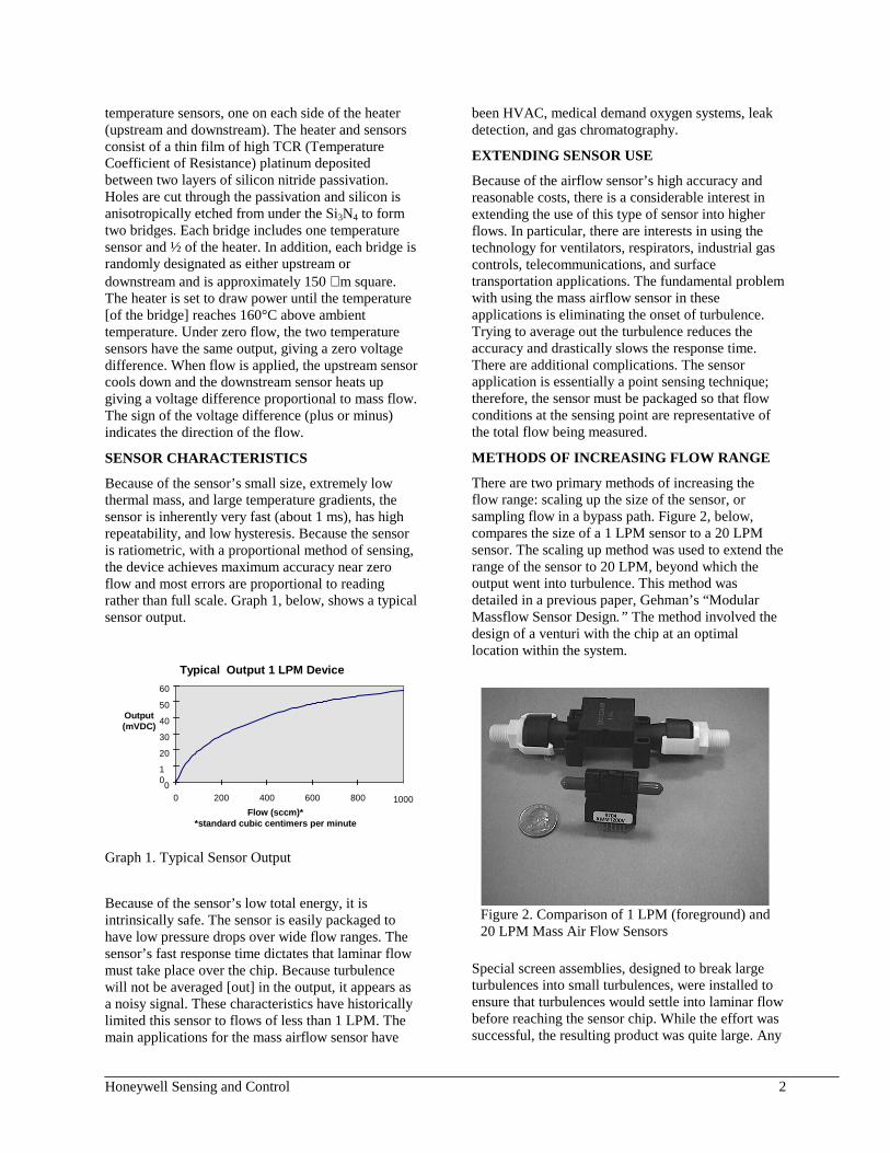
There are two primary methods of increasing the flow range: scaling up the size of the sensor, or sampling flow in a bypass path. Figure 2, below, compares the size of a 1 LPM sensor to a 20 LPM sensor. The scaling up method was used to extend the range of the sensor to 20 LPM, beyond which the output went into turbulence. This method was detailed in a previous paper, Gehman’s “Modular Massflow Sensor Design.” The method involved the design of a venturi with the chip at an optimal location within the system.
Figure 2. Comparison of 1 LPM (foreground) and 20 LPM Mass Air Flow Sensors
Special screen assemblies, designed to break large turbulences into small turbulences, were installed to ensure that turbulences would settle into laminar flow before reaching the sensor chip. While the effort was successful, the resulting product was quite large. Any
Honeywell Sensing and Control 3
further scale up would be unacceptable in most markets.
BYPASS APPROACH
The bypass approach to sensing flows substantially beyond 20 LPM is much more promising but much more challenging. The bypass method divides the flow. For instance, if the total flow is 100 LPM, 1% of the flow can be bypassed into a 1 LPM sensor. This saves space and the main flow need not be as conditioned as the flow in the bypass. Unfortunately, bypass design is as much an art as a technology. Although design equations exist, they are only approximate, having errors as high as +/-50 %, at higher bypass ratios. The problems to be solved in successful bypass design include the following:
1. Controlling and minimizing pressure drop to accommodate low pressure applications while maximizing dynamic range of sensing
2. Accuracy at very low flows 3. Turbulence generation by mechanical features of
the bypass, especially edges 4. Leaks within the system 5. Manufacturability and test/calibration techniques 6. Tradeoffs of sensor size versus maximum flow
rate PROTOTYPE DEVELOPMENT
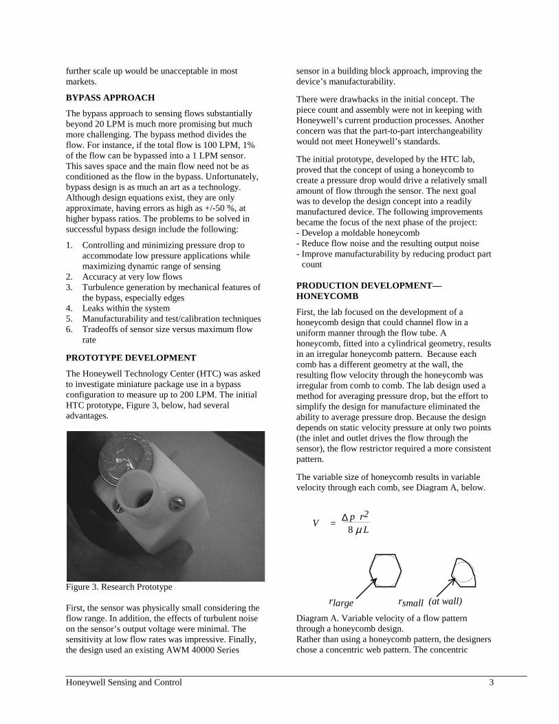
The Honeywell Technology Center (HTC) was asked to investigate miniature package use in a bypass configuration to measure up to 200 LPM. The initial HTC prototype, Figure 3, below, had several advantages.
Figure 3. Research Prototype First, the sensor was physically small considering the flow range. In addition, the effects of turbulent noise on the sensor’s output voltage were minimal. The sensitivity at low flow rates was impressive. Finally, the design used an existing AWM 40000 Series
sensor in a building block approach, improving the device’s manufacturability. There were drawbacks in the initial concept. The piece count and assembly were not in keeping with Honeywell’s current production processes. Another concern was that the part-to-part interchangeability would not meet Honeywell’s standards. The initial prototype, developed by the HTC lab, proved that the concept of using a honeycomb to create a pressure drop would drive a relatively small amount of flow through the sensor. The next goal was to develop the design concept into a readily manufactured device. The following improvements became the focus of the next phase of the project: - Develop a moldable honeycomb - Reduce flow noise and the resulting output noise - Improve manufacturability by reducing product part
count PRODUCTION DEVELOPMENT—HONEYCOMB
First, the lab focused on the development of a honeycomb design that could channel flow in a uniform manner through the flow tube. A honeycomb, fitted into a cylindrical geometry, results in an irregular honeycomb pattern. Because each comb has a different geometry at the wall, the resulting flow velocity through the honeycomb was irregular from comb to comb. The lab design used a method for averaging pressure drop, but the effort to simplify the design for manufacture eliminated the ability to average pressure drop. Because the design depends on static velocity pressure at only two points (the inlet and outlet drives the flow through the sensor), the flow restrictor required a more consistent pattern. The variable size of honeycomb results in variable velocity through each comb, see Diagram A, below.
V = ∆ p r28 µ L
rlarge rsmall (at wall)
Diagram A. Variable velocity of a flow pattern through a honeycomb design. Rather than using a honeycomb pattern, the designers chose a concentric web pattern. The concentric

Honeywell Sensing and Control 4
channels improved the flow pattern because each of the individual channel sections was identical. This approach ensured the same flow through each channel section and a uniform flow through the tube. The radius is related to the hydraulic diameter that is approximately the gap of each web; see Diagram B below. This design produced a more consistent velocity throughout the flow path.
r
r
Diagram B. Relationship of the honeycomb radius to the hydraulic diameter. FLOW RESTRICTOR LENGTH
The next goal centered on minimizing output noise and reducing pressure drop. Output noise is related to both Reynolds’ number and flow eddies that are produced by sharp edges, and changes in flow direction. Pressure drop negatively affects the performance of flow generators such as fans and blowers. Reduced pressure drop reduces the sensitivity of flow generators and improves their performance. Reducing the length of the flow channel decreases pressure drop but increases the Reynolds’ number at the flow sensor pressure inlet. Experiments revealed that the shorter flow channel did not significantly affect output noise. Based on these findings, the length of the flow channel was reduced, minimizing pressure drop. PRODUCT MANUFACTURABILITY
Generally, each part added to an assembly increases part cost, assembly cost, assembly error risk, and ultimately, reliability risk. The initial lab prototype was comprised of 13 parts: flow channel, 3 honeycombs, 5 o-rings, flow tube, circuit, base housing, and cover. In manufacture, the first simplification involved modifying the honeycomb to a concentric tube geometry. This modification allowed integration of the flow tube into the housing, eliminating the need for 3 o-rings, the honeycomb and tube. Experiments determined that the up and downstream honeycomb straighteners were not required in the new design. Further design analysis reduced the total product to three parts without
compromising performance. The parts included: the housing with molded-in flow channel, the circuit, and the cover. The revised product design required minimal operations and resulted in a cost effective, producible, and reliable product. Figure 4, below, shows the resulting production prototype design.
Figure 4. Production Prototype PROTOTYPE TEST FINDINGS
Testing a 200 SLPM (standard liters per minute) device requires a laminar flow to the sensor. This challenge required placing a baffle chamber with honeycombed flow passages and polyester screens in the flow path to reduce the large turbulences into smaller micro turbulences. This reduced the distance needed for the flow to stabilize. A commercially available 200 SLPM mass airflow controller directed the flow to the sensor. A digital voltmeter (DVM) and an oscilloscope monitored the sensor output. Graph 2, below, shows the typical output of the device.
Output of 200LPM Prototype
0.0000.5001.0001.5002.0002.5003.0003.5004.0004.5005.000
0 50 100 150 200
Flow (LPM)
Output (Vdc)
Graph 2. Typical Output of 200 LPM Prototype
Honeywell Sensing and Control 5
The oscilloscope monitored the quality of the flow signal to show the amount of turbulent airflow signal imposed on the DC sensor signal. CONCLUSION
Based on these successful efforts, designers are currently focusing their efforts on extending the present prototype to flow rates as high as 5 kLPM. However, they face severe challenges testing such devices, especially in generating known controlled flows of such magnitude. Physical design work requires extensive computational fluid dynamics (CFD) modeling. ACKNOWLEDGMENTS
The authors gratefully acknowledge the contributions of Dr. Ulrich Bonne of the Honeywell Technology Center (Minnesota) who developed the first successful bypass concept.
REFERENCES
1. R.W. Gehman with P.J. Bohrer, R.G. Johnson, R. H. Higashi. “Design and Packaging of a Highly Sensitive Microtransducer for Airflow and Differential Pressure Sensing Applications." Third International Conference on Solid State Sensors. Philadelphia, Pa. June 1985.
2. Kamiunten S. Aoshima, S et al. US Patent 5014552 FLOW SENSOR. May 14, 1991.
3. R. Gehman. “Modular Massflow Sensor Design." ISHM Proceedings. Boston, MA. Nov 1994.
4. Jamie Speldrich, US Patent Application. 5. Ulrich Bonne, memorandum dated 15 May 1998
“Technology Transfer: Sensor for Large Flows W/Bypass.”