Embed Size (px)
Citation preview
Reduced Instruction Set Computer Architecture
Since the earliest days of the computer era, the general trend in computer architecture and organization has been toward increas- ing CPU complexity: larger instruction sets, more addressing modes, more specialized registers, and the like. However, in the past several years, there has been increasing interest in an innova- tive approach to computer architecture: the reduced instruction set computer (RISC). The intended performance benefits of RISC, compared to a more conventional approach, include more effec- tive compilers, no use of microcode, more effective pipelining, and improved response to interrupts. Key characteristics of the RlSC approach include: a limited and simple instruction set; the use of eithera large number of registers (hundreds) or an Optimizing com- piler, to maximize the use of registers and minimize references to main memory; an emphasis on optimizing the instruction execu- tion pipeline.
This paper presents a tutorial on the RlSC approach and high- lights the key design issues involved in RlSC architecture. We begin by looking at the results of a number of studies on the instruction execution characteristics of compiled high-level language pro- grams. The results of these studies inspired the RlSC movement. The paper then summarizes approaches to three key RlSC design issues: optimized register usage, reduced instruction sets, and pipelining. As examples, an experimental system, the Berkeley RISC, and a commercial system, the MIPS R2000, are presented. The paper closes with a discussion of the RlSC versus CISC (com- plex instruction set computer) controversy.
I . INTRODUCTION
Since the development of the stored-program computer around 1950, there have been remarkably few true inno- vations in the areas of computer organization and archi- tecture. One of the most interesting and, potentially, one of the most important innovations i s the reduced instruc- tion set computer (RISC). The RlSC architecture is a dra- matic departure from the historical trend in CPU architec- ture and challenges the conventional wisdom expressed in words and deeds by most computer architects. An analysis of the RlSC architecture brings into focus many of the important issues in computer organization and architec- ture.
Most of the work has been on experimental systems, but commercial RlSC systems have begun to appear [1]-[12].
Manuscript received December 3,1986; revised August 21,1987. The submission of this paper was encouraged after review of an advance proposal.
The author is at 5 Chesterford Gardens, London NW3 7DD, England.
I E E E Log Number 8717881.
~~~~~ ~
00189219/88/01~38$01.00 0 1988 IEEE
Recently, both IBM (with its RT PC) and Hewlett-Packard (with its900series) have introduced machinesthat have both RlSC and conventional characteristics [13], [14]. Although RlSC systems have been defined and designed in a variety of ways by different groups, the key elements shared by most (not all) designs are these:
a limited and simple instruction set; the use of either a hardware or compiler strategy to maximizethe useof registersand minimize references to main memory; - am emphasis on optimizing the instruction execution pipeline.
This paper surveys key design issues relating to RlSC architecture. To begin, we present a brief survey of some results on instruction sets that inspired much of the RlSC work.
II. INSTRUCTION EXECUTION CHARACTERISTICS
Oneof the mostvisible formsof evolution associated with computers is that of programming languages. As the cost of hardware has dropped, the relative cost of software has risen. Along with that, a chronic shortage of programmers has driven up software costs in absolute terms. Thus the major cost in the life cycle of a system is software, not hard- ware. Adding to ihe cost, and to the inconvenience, i s the element of unreliability: It i s common for programs, both system and application, to continue to exhibit new bugs after years of operation.
The response from researchers and industry has been to develop ever more powerful and complex high-level pro- gramming languages (compare Fortran to Ada). These high- level languages (HLL) allow the programmer to express algorithms more concisely, take care of much of the detail, and often support naturally the use of structured program- ming.
Alas, this solution gave rise to another problem, known as the semanticgap, the difference between the operations provided in HLLs and those provided in computer archi- tecture. Symptoms of this gap are alleged to include exe- cution inefficiency, excessive program size, and compiler complexity. Designers responded with architectures intended to close this gap. Key features include large
38 PROCEEDINGS OF THE IEEE, VOL. 76, NO. 1, JANUARY 1988
instruction sets, dozens of addressing modes, and various HLL statements implemented in hardware. An example of the latter is the CASE machine instruction on the VAX-11. Such complex instruction sets are intended to
ease the task of the compiler writer; improve execution efficiency, since complex sequences of operations can be implemented in microcode; provide support for even more complex and sophis- ticated HLLs.
Meanwhile,a numberof studies have been doneoverthe years to determine the characteristics and patterns of exe- cution of machine instructions generated from HLL pro- grams. The results of these studies inspired some research- ers to look for an altogether differerlt approach: namely, to make the architecture that supports the HLL simpler, rather than more complex.
So, to understand the line of reasoning of the RlSC advo- cates, we begin with a brief review of instruction execution characteristics. The aspects of computation of interest are
Operations Performed:These determine the functions to be performed by the CPU and i t s interaction with mem- ory.
Operands Used: The types of operands and the fre- quency of their use determine the memory organization for storing them and the addressing modes for accessing them.
€xecution Sequencing: This determines the control and pipeline organization.
In the remainder of this section, we summarize the results of a number of studies of high-level language programs. All of the results are based on dynamic measurements [15].That is, measurements are collected by executing the program and counting the number of times some feature has appeared or a particular property has held true. In contrast, static measurements merely perform these counts on the source text of a program. They give no useful information on performance, because they are not weighted relative to the number of times each statement is executed.
The remainder seldom had more than one operator. Tanen- baum [ I 7 published measurements of HLL constructs, col- lected from over 300 procedures used in operating-system programs and written in a language that supports struc- tured programming (SAL). Patterson and Sequin [18], two of the key figures in the Berkeley RlSC project, analyzed a set of measurements taken in the early stages of the RlSC effort. Measurements were collected from compilers and from programs for typesetting, CAD, sorting, and file com- parison. The programming languages C and Pascal were studied. Huck [I91 analyzed four programs intended to rep- resent a mix of general-purpose and scientific computing, including fast Fourier transform and integration of systems of differential equations.
There is quite good agreement in the results of this mix- ture of languages and applications. Assignment statements predominate, suggesting that the simple movement of data isof high importance.There isalsoa preponderanceof con- ditional statements (IF, LOOP). These statements are imple- mented in machine language with some sort of compare and branch instruction. This suggests that the sequence control mechanism of the instruction set is important.
These results are instructive to the machine instruction set designer, indicating which types of statements occur most often and therefore should be supported in an "opti- mal" fashion. However, these results do not reveal which statements use the most time in the execution of a typical program. That is, given a compiled machine language pro- gram, which statements in the source language cause the execution of the most machine-language instructions?
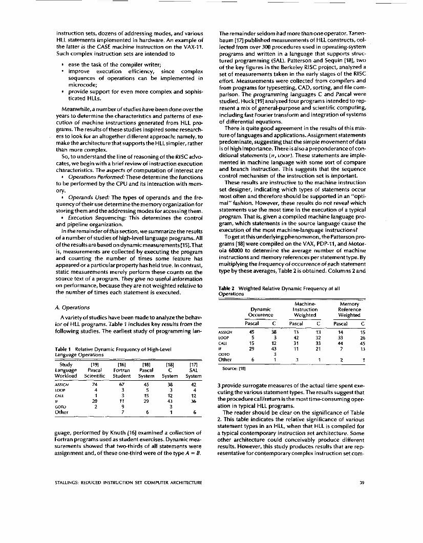
To get at this underlying phenomenon, the Patterson pro- grams [I81 were compiled on the VAX, PDP-11, and Motor- ola MOO0 to determine the average number of machine instructions and memory references per statement type. By multiplying the frequency of Occurrence of each statement type by these averages, Table 2 is obtained. Columns 2 and
Table 2 Weighted Relative Dynamic Frequency of all ODerations
A. Operations
A variety of studies have been made to analyze the behav- ior of HLL programs. Table 1 includes key results from the following studies. The earliest study of programming lan-
Table 1 Relative Dynamic Frequency of High-Level Language Operations
Study [I 91 [I 61 [I81 [I81 [I71 Language Pascal Fortran Pascal C SAL Workload Scientific Student System System System
Machine- Memory Dynamic Instruction Reference
Occu rence Weighted Weighted
Pascal C Pascal C Pascal C
ASSIGN 45 38 13 13 14 15 LOOP 5 3 42 32 33 26 CALL 15 12 31 33 44 45 IF 29 43 11 21 7 13 COT0 3 Other 6 1 3 1 2 1
Source: [18]
ASSIGN 74 67 45 38 42 LOOP 4 3 5 3 4 CALL 1 3 15 12 12 IF 20 11 29 43 36 GOT0 2 9 3 Other 7 6 1 6
guage, performed by Knuth [I61 examined a collection of Fortran programs used as student exercises. Dynamic mea- surements showed that two-thirds of all statements were assignment and, of these one-third were of the type A = B.
3 provide surrogate measures of the actual time spent exe- cuting the various statement types. The results suggest that the procedurecalllreturn is the most time-consuming oper- ation in typical HLL programs.
The reader should be clear on the significance of Table 2. This table indicates the relative significance of various statement types in an HLL, when that HLL is compiled for a typical contemporary instruction set architecture. Some other architecture could conceivably produce different results. However, this study produces results that are rep- resentative for contemporary complex instruction set com-
STALLINGS: REDUCED INSTRUCTION SET COMPUTER ARCHITECTURE 39
puter (CISC) architectures. Thus they can provideguidance to those looking for more efficient ways to support HLLs.
B. Operands
Much lesswork has been doneon theoccurrenceof types of operands, despite the importance of this topic. There are several aspects that are significant.
The Patterson study already referenced [I81 also looked at the dynamic frequency of occurrence of classes of vari- ables (Table 3). The results, consistent between Pascal and
Table 3 Dynamic Percentage of Operands
Pascal C Average
Integer constant 16 23 20 Scalar Variable 58 53 55 Arrayktructure 26 24 25
C programs, show that the majorityof references are to sim- ple scalar variables. Further, over 80 percent of the scalars were local (to the procedure) variables. In addition, ref- erences to arraydstructures require a previous reference to their index or pointer, which again i s usually a local sca- lar. Thus there i s a preponderance of references to scalars, and these are highly localized.
The Patterson study examined the dynamic behavior of HLL programs, independent of the underlying architecture. As discussed earlier, it i s necessary todeal with actual archi- tectures to examine program behavior more deeply. One study, [20], examined DEC-10 instructions dynamically and found that each instruction on the average references 0.5 operands in memory and 1.4 registers. Similar results are reported in [I91 for C, Pascal, and Fortran programs on S/370, PDP-11, and VAX-11. Of course, these figures depend highly on both the architecture and the compiler, but they do illustrate the frequency of operand accessing.
These latter studies suggest the importance of an archi- tecture that lends itself to fast operand accessing, since this operation is performed so frequently. The Patterson study suggests that a prime candidate for optimization is the mechanism for storing and accessing local scalar variables.
C. Procedure Calls
We have seen that procedure calls and returns are an important aspect of HLL programs. The evidence (Table 2)
Time
suggests that these are the most time-consuming opera- tions in the compiled HLL programs. Thus it will be prof- itable to consider ways of implementing these operations efficiently. Two aspects are significant: the number of parameters and variables that a procedure deals with, and the depth of nesting.
In Tanenbaum‘s study [Iq, he found that 98 percent of dynamically called procedures were passed fewer than six arguments, and that 92 percent of them used fewer than six local scalar variables. Similar results were reported by the Berkeley RlSC team [21], as shown in Table 4. These results
Table 4 Procedure Arguments and Local Scalar Variables
Percentage of Executed Procedure Calls with
Compiler, Small Interpreter and Nonnumeric
Typesetter Programs (percent) (percent)
> 3 arguments > 5 arguments > 8 words of arguments
> 12 words of arguments and local scalars
and local scalars
0-7 0-5 0-3 0
1-20
1-6
0-6
0-3
show that the number of words required per procedure activation i s not large. The studies reported earlier indi- cated that a high proportion of operand references are to local scalar variables. The studies just mentioned show that those references are, in fact, confined to relatively few vari- ables.
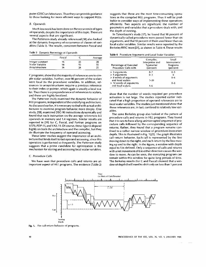
The same Berkeley group also looked at the pattern of procedure calls and returns in HLL programs. They found that it i s rare to have a long uninterrupted sequence of pro- cedure calls followed by the corresponding sequence of returns. Rather, they found that a program remains con- fined to a rather narrow window of procedure-invocation depth. This is illustrated in Fig. 1 [22]. The graph illustrates call-return behavior. Each call is represented by the line moving down to the right, and each return by the line mov- ing up and to the right. In the figure, a window with depth equal to 5 i s defined. Only a sequence of calls and returns with a net movement of 6 in either direction causes thewin- dow to move. As can be seen, the executing program can remain within this window for quite long periods of time. The Berkeley results (for C and Pascal) showed that a win- dow of depth 8 will need to shift only on less than 1 percent
(in Units of CallsiRetums)
~
I I I It . I I
I 1 l w = s y \ I I A / \
1 Fig. 1. The
Nesting Depth
call-return behavior of programs.
40 PROCEEDINGS OF THE IEEE, VOL. 76, NO. 1, JANUARY 1988
of the calls or returns [23]. These results also suggest that operand references are highly localized.
D. Implications
A number of groups have looked at results such as those just reported and have concluded that the attempt to make the instruction set architecture close to HLLs is not the most effective design strategy. Rather, the HLLs can best be sup- ported by optimizing performance of the most time-con- suming features of typical HLL programs.
Generalizing from the work of a number of researchers, three elements emerge that, by and large, characterized RlSC architectures. First, use a large number of registers. This i s intended tooptimizeoperand referencing.The stud- ies just discussed showthat thereare several references per HLL instruction, and that there is a high proportion of move (assignment) statements. This, coupled with the locality and predominance of scalar references, suggests that perfor- mance can be improved by reducing memory references at the expense of more register references. Because of the locality of these references, an expanded register set seems practical.
Second, careful attention needs to be paid to the design of instruction pipelines. Because of the high proportion of conditional branch and procedure call instructions, a straightforward instruction pipeline will be inefficient. This manifests itself as a high proportion of instructions that are pre-fetched but never executed.
Finally, a simplified (reduced) instruction set is indicated. This point is not asobviousas theothers, but should become clearer in the ensuing discussion. In addition, we will see that the desire to implement an entire CPU on a single chip leads to a reduced instruction set solution.
Ill. OPTIMIZED REGISTER USAGE
The results summarized above point out the desirability of quick access to operands that are referenced frequently. We have seen that there is a large proportion of assignment statements in HLL programs, and many of these are of the simple form A = B. Also, there are a significant number of operand accesses per HLL statement. If we couple these results with the fact that most accesses are to local scalars, heavy reliance on register storage is suggested.
The reason that register storage is indicated is that it is the fastest available storage device, faster than both main memory and cache. The register file is physically small, gen- erally on the same chip as the ALU and control unit, and employs much shorter addresses than addresses for cache and memory. Thus a strategy is needed that will allow the most frequently accessed operands to be kept in registers and to minimize register-memory operations.
Two basic approaches are possible, one based on soft- ware and the other on hardware. The software approach is to rely on the compiler to maximize register usage. The compiler will attempt to allocate registers to those variables that will be used the most in a given time period. This approach requires the use of sophisticated program-anal- ysis algorithms. The hardware approach is simply to use more registers so that more variables can be held in reg- isters for longer periods of time. This section presents both approaches.
To provide some context for this section, the following subsections discuss design issues related to CPU registers.
A. Registers
To understand the role of registers in the CPU, let us con- sider the requirements placed on the CPU, the things that it must do:
Fetch instructions: The CPU must read instructions from memory.
lnterpret instructions: The instruction must be decoded to determine what action is required.
Fetch data:The execution of an instruction may require reading data from memory or an IIO module.
Process data: The execution of an instruction may require performing some arithmetic or logical operation on data.
Write data: The results of an execution may require writing data to memory or an 110 module.
To be able to do these things, it should be clear that the CPU needs to temporarily store some data. The CPU must remember the location of the last instruction so that it can know where to get the next instruction. It needs to store instructions and data temporarily while an instruction is being executed. In other words, the CPU needs a small internal memory. This memory consists of a set of high- speed registers. The registers in the CPU serve two func- tions:
User-visible registers: These enable the machine- or assembly-language programmer to minimize main-mem- ory references by optimizing use of registers.
Control and status registers: These are used by the control unit to control theoperation of the CPU and by priv- ileged, operating system programs to control the execution of programs.
There is no clean separation of registers into these two categories. For example, on some machines the program counter is user-visible (e.g., VAX-11 architecture), but on many it is not. For purposes of the following discussion, however, we will use these categories.
B. User-Visible Registers
A user-visible register is one which may be referenced by means of the machine language that the CPU executes. Vir- tually all contemporary CPU designs provide for a number of user-visible registers, as opposed to a single accumu- lator. We can characterize these in the following categories:
General Purpose Data Address Condition Codes.
General-purpose registers can be assigned to a variety of functions by the programmer. Sometimes, their use within the instruction set is orthogonal to the operation; that is, any general-purpose register can contain the operand for any opcode. This provides true general-purpose register use. Often, however, there are restrictions. For example, there may be dedicated registers for floating-point oper- ations.
In some cases, general-purpose registers cap be used for addressing functions (e.g., register indirect, displacement). In other cases, there is a partial or clean separation between data registers and address registers. Data registers may only be used to hold data and cannot be employed in the cal- culation of an operand address. Address registers may themselves be somewhat general-purpose, or they may be
STALLINCS: REDUCED INSTRUCTION SET COMPUTER ARCHITECTURE 41
devoted to a particular addressing mode. Examples of reg- isters are as follows:
Segment pointers: In a machine with segmented addressing, a segment register holds the address of the base of the segment. There may be multiple registers, for exam- ple, one for the operating system and one for the current process.
Index registers: These are used for indexed address- ing, and may be autoindexed.
Stack pointer: If there i s user-visible stack addressing, then typically the stack i s in memory and there i s a dedi- cated register that points to the top of the stack. This allows implicit addressing; that is, push, pop, and other stack instructions need not contain an explicit stack operand.
There are several design issues to be addressed here. An important one is whether to use completely general-pur- pose registers or to specialize their use. With the use of spe- cialized registers, it can generally be implicit in the opcode which type of register a certain operand specifier refers to. The operand specifier must only identify one of a set of spe- cialized registers rather than one out of all the registers, thus saving bits. On the other hand, this specialization lim- its the programmer’s flexibility. There is no final and best solution to this design issue, but, the trend seems to be toward the use of specialized registers.
Another design issue is the number of registers, either general-purpose or data-plus-address, to be provided. Again, this affects instruction set design since more reg- isters require more operand specifier bits. Somewhere between 8 and 32 registers appears optimum [20]. Fewer registers result in more memory references; more registers do not noticeably reduce memory references. However, a new approach, which finds advantage in the use of hundreds of registers, is exhibited in some RlSC systems.
Finally, there i s the issue of register length. Registers that must hold addresses obviously must be at least long enough to hold the largest address. Data registers should be able to hold values of most data types. Some machines allow two contiguous registers to be used as one for holding double- length values.
A final category of registers, which i s at least partially vis- ible to the user, holds condition codes (also referred to as flags). Condition codes are bits set by the CPU hardware as the result of operations. For example, an arithmetic oper- ation may produce a positive, negative, zero, or overflow result. In addition to the result itself being stored in a reg- ister or memory, a condition code is also set. The code may subsequently be tested as part of aconditional branch oper- ation.
Condition code bits are collected into one or more reg- isters. Usually, they form part of a control register. Gen-
erally, machine instructions allow these bits to be read by implicit reference, but they cannot be altered by the pro- grammer.
In some machines, a subroutine call will result in the automatic saving of all user-visible registers, which are to be restored on return. The saving and restoring i s per- formed by the CPU as part of the execution of call-and- return instructions. This allows each subroutine to use the user-visible registers independently. On other machines, it i s the responsibility of the programmer to save the con- tents of the relevant user-visible registers prior to a sub- routinecall by including instructionsforthis purpose in the program.
C. The Hardware Approach
The hardware approach has been pioneered by the Berkeley RlSC group [I81 and is used in the first commercial RlSC product, the Pyramid [24].
Register Windows: On the face of it, the use of a large set of registers should decrease the need to access memory. Thedesign task is toorganize the registers in such afashion that this goal i s realized.
Since most operand references are to local scalars, the obvious approach is to store these in registers, with per- haps a few registers reserved for global variables. The prob- lem is that the definition of local changes with each pro- cedure call and return, operations that occur frequently. On every call, local variables must be saved from the reg- isters into memory, so that the registers can be reused by the called program. Furthermore, parameters must be passed. On return, thevariablesof the parent program must be restored (loaded back into registers)and results must be passed back to the parent program.
Thesolution i s based ontwoother results reported above. First, a typical procedure employs only a few passed param- eters and local variables. Second, the depth of procedure activation fluctuates within a relatively narrow range (Fig. 1). To exploit these properties, multiple small sets of reg- isters are used, each assigned to a different procedure. A procedure call automatically switches the CPU to use a dif- ferent fixed-size window of registers, rather than saving registers in memory. Windows for adjacent procedures are overlapped to allow parameter passing.
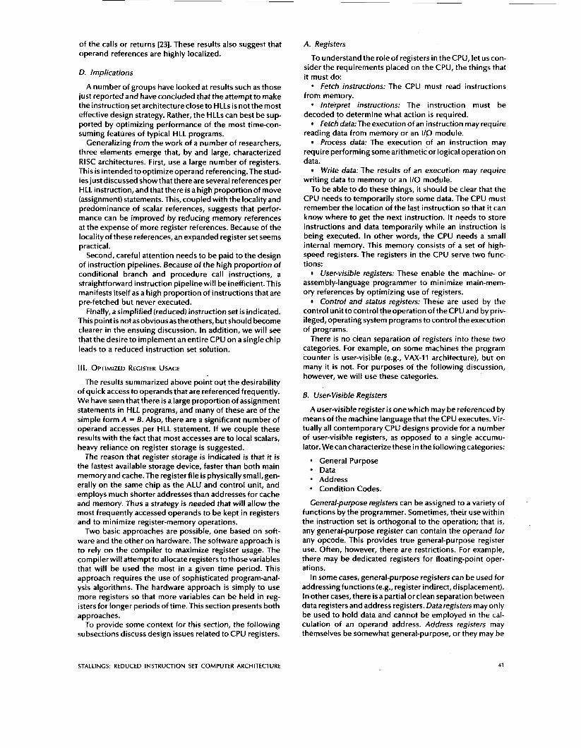
The concept is illustrated in Fig. 2. At any time, only one window of registers is visible and is addressable as if it were the only set of registers (e.g., address 0 through N - 1). The window is divided into three fixed-size areas. Parameter registers hold parameters passed down from the procedure that called the current procedure and results to be passed back up. Local registers are used for local variables, as assigned by the compiler. Temporary registers are used to
Parameter Temporary Registers - Call/retum
*
Fig. 2. Overlapping register windows.
42 PROCEEDINGS OF THE IEEE, VOL. 76, NO. 1, JANUARY 1988
exchange parameters and results with the next lower level (procedure called by current procedure). The temporary registers at one level are physically the same as the param- eter registers at the next lower level. This overlap permits parameters to be passed without the actual movement of data.
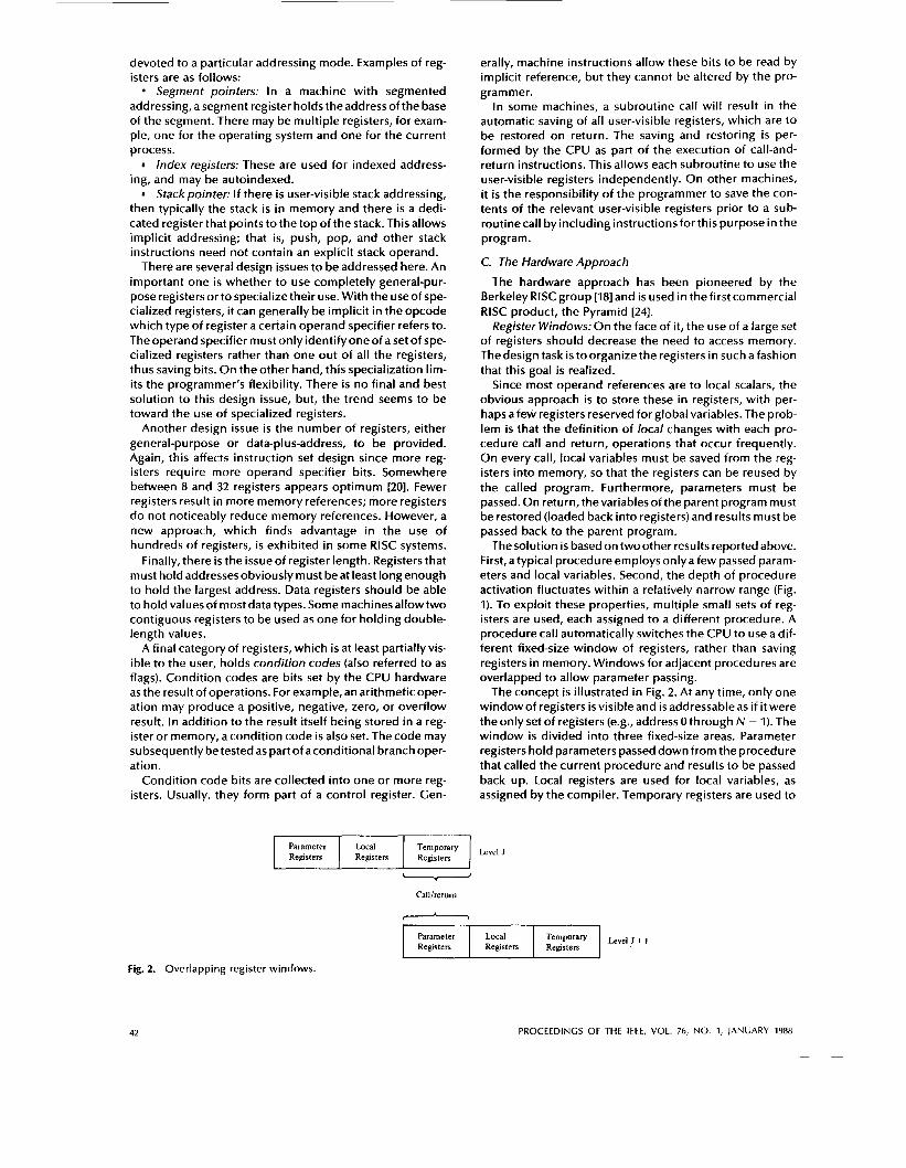
To handle any possible pattern of calls and returns, the number of register windows would have to be unbounded. Instead, the register windows can be used to hold the few most recent procedure activations. Older activations must be saved in memory and later restored when the nesting depth decreases. Thus the actual organization of the reg- ister file is as a circular buffer of overlapping windows.
This organization is shown in Fig. 3 [21], which depicts a circular buffer of six windows. The buffer is filled to a depth
Current- Window- Pointer
Call
Return
Fig. 3. Circular buffer organization of overlapped win- dows.
of 4 (A called B; B called C; C called D) with procedure D active. The current-window pointer (CWP) points to the window of the currently active procedure. Register refer- ences by a machine instruction are offset by this pointer to determine the actual physical register. The saved-window pointer identifies the window most recently saved in mem- ory. If procedure D now calls procedure E, arguments for fare placed in D's temporary registers (the overlap between w3 and w4) and the CWP is advanced by one window.
If procedure E then makes a call to procedure F, the call cannot be made with the current status of the buffer. This is because F's window overlaps A's window. If F begins to load its temporary registers, preparatory to a call, it will overwrite the parameter registers of A (A.param). Thus when CWP is incremented (modulo 6) so that it becomes equal to SWP, an interrupt occurs and A's window is saved. Only the first two portions (A.param and A.loc) need be saved. Then the SWP is incremented and the call to F proceeds. A similar interrrupt can occur on returns. For example, sub-
sequent to the activation of F, when B returns to A, CWP is decremented and becomes equal to SWP. This causes an interrupt that results in the restoral of A's window.
From the preceding, it can be seen that an N-window reg- ister file can hold only N - 1 procedure activations. The value of N need not be large. As was mentioned earlier, one study [23] found that, with eight windows, a save or restore is needed on only 1 percent of the calls or returns. The Berkeley RlSC computers use 8 windows of 16 registers each. The Pyramid computer employs Idwindows of 32 reg- isters each.
Global VariablesZThe window scheme just described pro- vides an efficient organization for storing local scalar vari- ables in registers. However, this scheme does not address the need to store global variables, those accessed by more than one procedure (e.g., COMMON variables in Fortran). Two options suggest themselves. First, variables declared as global in an HLL can be assigned memory locations by the compiler, and all machine instructions that reference these variables will use memory-reference operands. This is straightforward, from both the hardware and software (compiler) points of view. However, forfrequentlyaccessed global variables, this scheme is inefficient.
An alternative is to incorporate a set of global registers in the CPU. These registers would be fixed in number and available to all procedures. A unified numbering scheme can be used to simplify the instruction format. For example, references to registers 0 through 7 could refer to unique global registers, and references to registers 8 through 31 could be offset to refer to physical registers in the current window. Thus there is an increased hardware burden to accommodate the split in register addressing. In addition, the compiler must decide which global variables should be assigned to registers.
Large Register File versus Cache: The register file, or- ganized intowindows,actsasasmall,fast buffer for holding a subset of all variables that are likely to be used most heavily. From this point of view, the register file acts much like a cache memory. The question therefore arises as to whether it would be simpler and better to use a cache and a small traditional register file.
Table 5 compares characteristics of the two approaches. The window-based register file holds all of the local scalar variables (except in the rare case of window overflow) of the most recent N - 1 procedure activations. The cache holds a selection of recently used scalar variables. The register files should save time, since all local scalar variables are retained. On the other hand, thecache may make more effi- cient use of space, since it i s reacting to the situation dynamically. Furthermore, caches generally treat all mem- ory references alike, including instructions and other types
Table 5 Characteristics of Large Register File and Cache Organizations
Large Register File Cache
All Local Scalars Individual Variables Blocks of Memory Compiler-Assigned Global Recently Used Global
Variables Variables SavelRestore Based on SavelRestore Based on
Procedure Nesting Depth Cache Replacement
Recently Used Local Scalars
Algorithm Register Addressing Memory Addressing
STALLINGS: REDUCED INSTRUCTION SET COMPUTER ARCHITECTURE 43
of data. Thus savings in these other areas are possible with a cache and not a register file.
A register file may make inefficient use of space, since not all procedures will need the full window space allotted to them. On the other hand, the cache suffers from another sort of inefficiency: Data are read in blocks. Whereas the register file contains only those variables in use, the cache reads in a block of data, some or much of which will not be used.
The cache is capable of handling global as well as local variables. There are usually many global scalars, but only a few of them are heavily used [21]. A cache will dynamically discover these variables and hold them. If the window- based register file i s supplemented with global registers, it too can hold some global scalars. However, it i s difficult for a compiler to determine which globals will be heavily used.
With the register file, the movement of data between reg- isters and memory i s determined by the procedure nesting depth. Since this depth usually fluctuates within a narrow range, the use of memory i s relatively infrequent. Most cache memories are set-associative with a small set size. Thus there i s the danger that other data or instructions will displace, in the cache, frequently used variables.
Based on thediscussion sofar, thechoice between a large window-based register file and acache is not clear cut. There is one characteristic, however, in which the register approach i s clearly superior and which suggests that a cache-based system will be noticeably slower. This dis- tinction shows up in the amount of addressing overhead experienced by the two approaches.
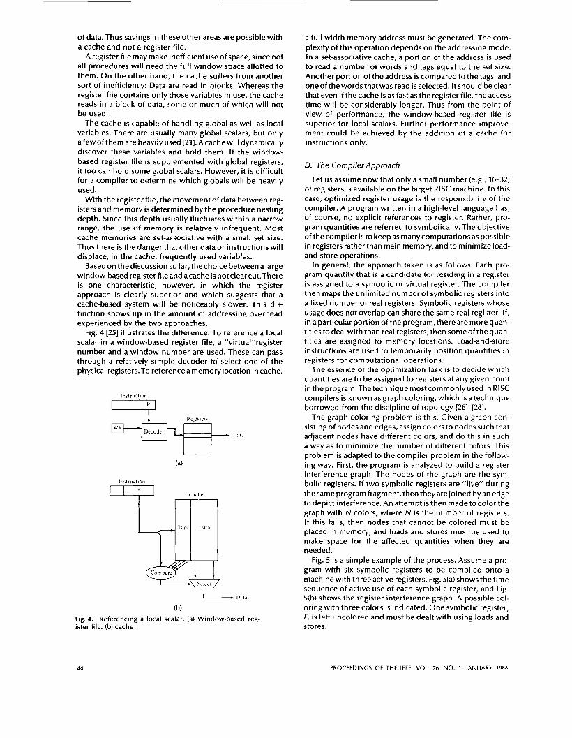
Fig. 4 [25] illustrates the difference. To reference a local scalar in a window-based register file, a “virtua1”register number and a window number are used. These can pass through a relatively simple decoder to select one of the physical registers.To reference a memory location in cache, , lnstruclii~”; ,
\L.IL.L I
-+-EL 1).,1.,
(b)
Fig. 4. Referencing a local scalar. (a) Window-based reg- ister file. (b) cache.
a full-width memory address must be generated. The com- plexity of this operation depends on the addressing mode. In a set-associative cache, a portion of the address is used to read a number of words and tags equal to the set size. Another portion of the address is compared to the tags, and oneofthewordsthatwas read isselected. ltshould beclear that even if the cache i s as fast as the register file, the access time will be considerably longer. Thus from the point of view of performance, the window-based register file i s superior for local scalars. Further performance improve- ment could be achieved by the addition of a cache for instructions only.
D. The Compiler Approach
Let us assume now that only a small number (e.g., 16-32) of registers is available on the target RISC machine. In this case, optimized register usage is the responsibility of the compiler. A program written in a high-level language has, of course, no explicit references to register. Rather, pro- gram quantities are referred to symbolically. The objective of thecompiler i s to keep as manycomputationsas possible in registers ratherthan main memory,and to minimize load- and-store operations.
In general, the approach taken i s as follows. Each pro- gram quantity that i s a candidate for residing in a register is assigned to a symbolic or virtual register. The compiler then maps the unlimited number of symbolic registers into a fixed number of real registers. Symbolic registers whose usage does not overlap can share the same real register. If, in a particular portion of the program, there are more quan- titiestodeal with than real registers, then someof thequan- tities are assigned to memory locations. Load-and-store instructions are used to temporarily position quantities in registers for computational operations.
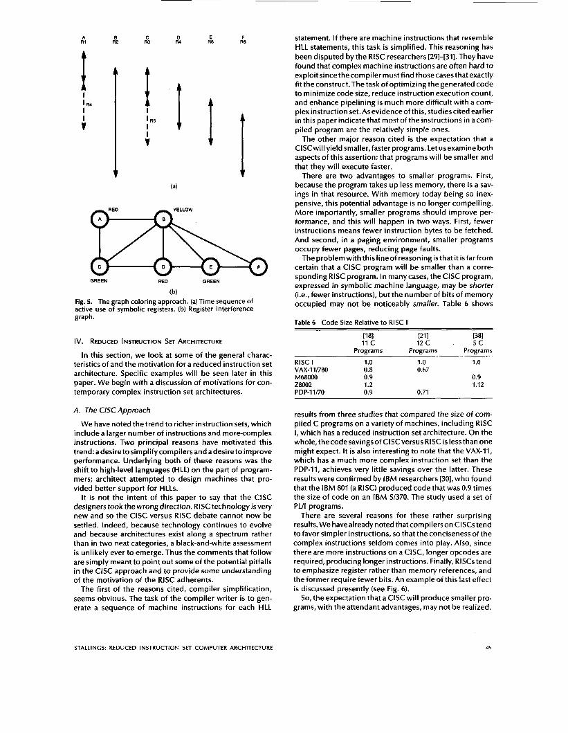
The essence of the optimization task i s to decide which quantities are to be assigned to registers at any given point in the program. The technique most commonly used in RlSC compilers i s known as graph coloring, which i s a technique borrowed from the discipline of topology [26]-[28].
The graph coloring problem i s this. Given a graph con- sisting of nodes and edges, assign colors to nodes such that adjacent nodes have different colors, and do this in such a way as to minimize the number of different colors. This problem is adapted to the compiler problem in the follow- ing way. First, the program is analyzed to build a register interference graph. The nodes of the graph are the sym- bolic registers. If two symbolic registers are “live” during the same program fragment, then they are joined by an edge to depict interference. An attempt i s then made to color the graph with N colors, where N i s the number of registers. If this fails, then nodes that cannot be colored must be placed in memory, and loads and stores must be used to make space for the affected quantities when they are needed.
Fig. 5 i s a simple example of the process. Assume a pro- gram with six symbolic registers to be compiled onto a machinewith threeactive registers. Fig. 5(a) shows the time sequence of active use of each symbolic register, and Fig. 5(b) shows the register interference graph. A possible col- oring with three colors is indicated. One symbolic register, F, is left uncolored and must be dealt with using loads and stores.
44 PROCEEDINGS OF THF IFFF VOI 76 NO 1 I A N I I A R V 19RR
A R I
I I
I lR4
B C R2 R3
E F R5 R6
GREEN RED GREEN
(b) Fig. 5. The graph coloring approach. (a) Time sequence of active use of symbolic registers. (b) Register interference graph.
IV. REDUCED INSTRUCTION SET ARCHITECTURE
In this section, we look at some of the general charac- teristics of and the motivation for a reduced instruction set architecture. Specific examples will be seen later in this paper. We begin with a discussion of motivations for con- temporary complex instruction set architectures.
A. The ClSC Approach
We have noted the trend to richer instruction sets, which include a larger number of instructions and more-complex instructions. Two principal reasons have motivated this trend: adesiretosimplifycompilers and adesireto improve performance. Underlying both of these reasons was the shift to high-level languages (HLL) on the part of program- mers; architect attempted to design machines that pro- vided better support for HLLs.
It is not the intent of this paper to say that the ClSC designers took the wrong direction. RlSC technology is very new and so the ClSC versus RlSC debate cannot now be settled. Indeed, because technology continues to evolve and because architectures exist along a spectrum rather than in two neat categories, a black-and-white assessment i s unlikely ever to emerge. Thus the comments that follow are simply meant to point out some of the potential pitfalls in the ClSC approach and to provide some understanding of the motivation of the RlSC adherents.
The first of the reasons cited, compiler simplification, seems obvious. The task of the compiler writer i s to gen- erate a sequence of machine instructions for each HLL
statement. If there are machine instructions that resemble HLL statements, this task i s simplified. This reasoning has been disputed by the RlSC researchers [29]-[31]. They have found that complex machine instructions are often hard to exploit sincethecompiler must find thosecasesthatexactly fit the construct. The task of optimizing the generated code to minimize code size, reduce instruction execution count, and enhance pipelining i s much more difficult with a com- plex instruction set.Asevidenceofthis, studiescited earlier in this paper indicate that most of the instructions in acom- piled program are the relatively simple ones.
The other major reason cited i s the expectation that a ClSCwill yield smaller, faster programs. Let us examine both aspects of this assertion: that programs will be smaller and that they will execute faster.
There are two advantages to smaller programs. First, because the program takes up less memory, there i s a sav- ings in that resource. With memory today being so inex- pensive, this potential advantage is no longer compelling. More importantly, smaller programs should improve per- formance, and this will happen in two ways. First, fewer instructions means fewer instruction bytes to be fetched. And second, in a paging environment, smaller programs occupy fewer pages, reducing page faults.
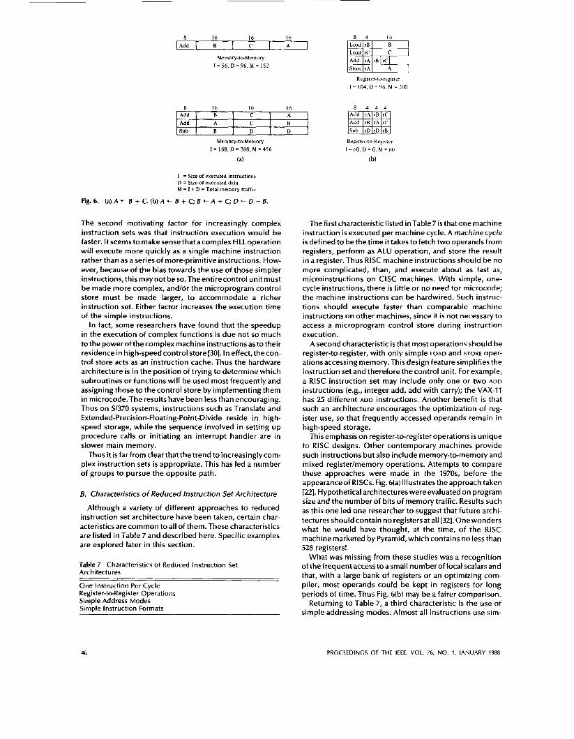
The problemwiththislineof reasoning isthat it isfarfrom certain that a ClSC program will be smaller than a corre- sponding RlSC program. In manycases, the ClSC program, expressed in symbolic machine language, may be shorter (i.e., fewer instructions), but the number of bits of memory occupied may not be noticeably smaller. Table 6 shows
Table 6 Code Size Relative to RlSC I
ti81 t211 t381 11 c 12 c 5c
Programs Programs Programs RlSC I 1 .o 1 .o 1 .o VAX-I 11780 0.8 0.67 M68000 0.9 0.9 za002 1.2 1.12 PD P-I 1 I70 0.9 0.71
results from three studies that compared the size of com- piled C programs on a variety of machines, including RlSC 1, which has a reduced instruction set architecture. On the whole, thecode savingsof ClSCversus RlSC is lessthan one might expect. It is also interesting to note that the VAX-11, which has a much more complex instruction set than the PDP-11, achieves very little savings over the latter. These results were confirmed by ISM researchers [30], who found that the IBM 801 (a RISC) produced code that was 0.9 times the size of code on an IBM S1370. The study used a set of PUI programs.
There are several reasons for these rather surprising results. We havealreadynoted thatcompilerson ClSCstend to favor simpler instructions, so that the conciseness of the complex instructions seldom comes into play. Also, since there are more instructions on a CISC, longer opcodes are required, producing longer instructions. Finally, RlSCs tend to emphasize register rather than memory references, and the former require fewer bits. An example of this last effect i s discussed presently (see Fig. 6).
So, the expectation that a ClSC will produce smaller pro- grams, with the attendant advantages, may not be realized.
STALLINGS: REDUCED INSTRUCTION SET COMPUTER ARCHITECTURE 45
Add 1 B I C 1 A
Memory-to-Memory I = 56, D = 9 6 , U = 152
8 16 16 16 Add B C A ’ Add A C B Sub B D
Load rB B Load rC C Add rA rB]rC] Store rA A
8 16 16 16
Add I A l C l R Add I B l C I A
Memory-to-Memory I = 168, D = 288, M = 456
(a)
I = Size o f executed instructions D = Size of executed data M = I + D = Total memory traffic
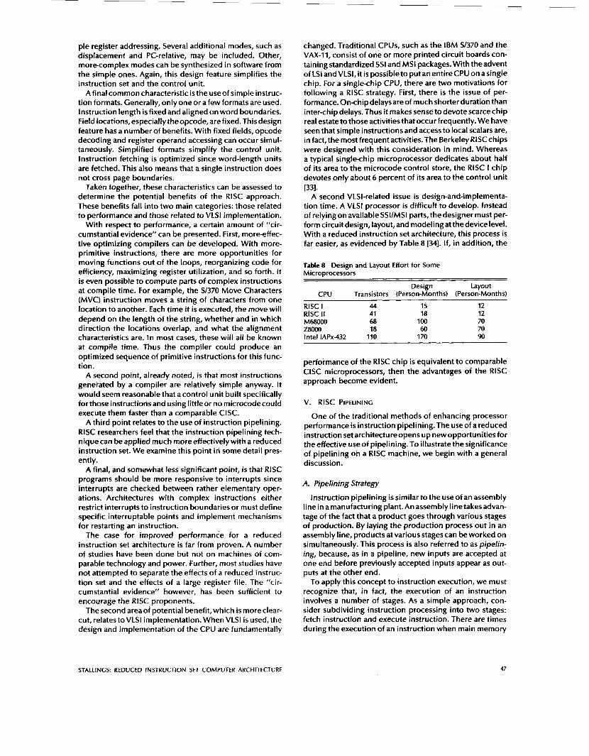
Fig. 6. (a)A + B + C. (b) A + B + C; B + A + C; D + D - B.
The second motivating factor for increasingly complex instruction sets was that instruction execution would be faster. It seems to make sense that a complex HLL operation will execute more quickly as a single machine instruction rather than as a series of more-primitive instructions. How- ever, because of the bias towards the use of those simpler instructions, this may not be so.Theentirecontrol unit must be made more complex, and/or the microprogram control store must be made larger, to accommodate a richer instruction set. Either factor increases the execution time of the simple instructions.
In fact, some researchers have found that the speedup in the execution of complex functions i s due not so much to the power of the complex machine instructions as to their residence in high-speedcontrol store[30]. In effect,thecon- trol store acts as an instruction cache. Thus the hardware architecture i s in the position of trying to determine which subroutines or functions will be used most frequently and assigning those to the control store by implementing them in microcode.The results have been less than encouraging. Thus on S/370 systems, instructions such as Translate and Extended-Precision-Floating-Point-Divide reside in high- speed storage, while the sequence involved in setting up procedure calls or initiating an interrupt handler are in slower main memory.
Thus it isfar from clearthatthetrend to increasinglycom- plex instruction sets i s appropriate. This has led a number of groups to pursue the opposite path.
B. Characteristics of Reduced Instruction Set Architecture
Although a variety of different approaches to reduced instruction set architecture have been taken, certain char- acteristics are common to all of them. These characteristics are listed in Table 7 and described here. Specific examples are explored later in this section.
Table 7 Characteristics of Reduced Instruction Set Architectures
One Instruction Per Cycle Register-to-Register Operations Simple Address Modes SimDle Instruction Formats
The first characteristiclisted inTable7is thatonemachine instruction is executed per machine cycle. A machine cycle i s defined to be the time it takes to fetch two operands from registers, perform as ALU operation, and store the result in a register. Thus RlSC machine instructions should be no more complicated, than, and execute about as fast as, microinstructions on ClSC machines. With simple, one- cycle instructions, there is little or no need for microcode; the machine instructions can be hardwired. Such instruc- tions should execute faster than comparable machine instructions on other machines, since it i s not necessary to access a microprogram control store during instruction execution.
A second characteristic i s that most operations should be register-to-register, with only simple LOAD and STORE oper- ations accessing memory.This design feature simplifies the instruction set and therefore the control unit. For example, a RlSC instruction set may include only one or two ADD
instructions (e.g., integer add, add with carry); the VAX-11 has 25 different ADD instructions. Another benefit i s that such an architecture encourages the optimization of reg- ister use, so that frequently accessed operands remain in high-speed storage.
This emphasis on register-to-register operations i s unique to RlSC designs. Other contemporary machines provide such instructions but also include memory-to-memory and mixed register/memory operations. Attempts to compare these approaches were made in the 1 9 7 0 ~ ~ before the appearance of RISCs. Fig. 6(a) illustrates the approach taken [22]. Hypothetical architectures were evaluated on program size and the number of bits of memory traffic. Results such as this one led one researcher to suggest that future archi- tectures should contain no registers at all [32]. Onewonders what he would have thought, at the time, of the RlSC machine marketed by Pyramid, which contains no less than 528 registers!
What was missing from these studies was a recognition of the frequent accesstoasmall number of local scalars and that, with a large bank of registers or an optimizing com- piler, most operands could be kept in registers for long periods of time. Thus Fig. 6(b) may be a fairer comparison.
Returning to Table 7, a third characteristic is the use of simple addressing modes. Almost all instructions use sim-
46 PROCEEDINGS OF THE IEEE, VOL. 76, NO. 1, JANUARY 1988
ple register addressing. Several additional modes, such as displacement and PC-relative, may be included. Other, more-complex modes can be synthesized in software from the simple ones. Again, this design feature simplifies the instruction set and the control unit.
Afinal common characteristic is the useof simple instruc- tion formats. Generally, only one or a few formats are used. Instruction length is fixed and aligned on word boundaries. Field locations, especially theopcode, are fixed. This design feature has a number of benefits. With fixed fields, opcode decoding and register operand accessing can occur simul- taneously. Simplified formats simplify the control unit. Instruction fetching is optimized since word-length units are fetched. This also means that a single instruction does not cross page boundaries.
Taken together, these characteristics can be assessed to determine the potential benefits of the RlSC approach. These benefits fall into two main categories: those related to performance and those related to VLSl implementation.
With respect to performance, a certain amount of "cir- cumstantial evidence" can be presented. First, more-effec- tive optimizing compilers can be developed. With more- primitive instructions, there are more opportunities for moving functions out of the loops, reorganizing code for efficiency, maximizing register utilization, and so forth. It i s even possible to compute parts of complex instructions at compile time. For example, the S/370 Move Characters (MVC) instruction moves a string of characters from one location to another. Each time it is executed, the move will depend on the length of the string, whether and in which direction the locations overlap, and what the alignment characteristics are. In most cases, these will all be known at compile time. Thus the compiler could produce an optimized sequence of primitive instructions for this func- tion.
A second point, already noted, is that most instructions generated by a compiler are relatively simple anyway. It would seem reasonable that a control unit built specifically forthose instructions and using littleor no microcodecould execute them faster than a comparable CISC.
A third point relates to the use of instruction pipelining. RlSC researchers feel that the instruction pipelining tech- nique can beapplied much more effectivelywith a reduced instruction set. We examine this point in some detail pres- ently.
A final, and somewhat less significant point, is that RlSC programs should be more responsive to interrupts since interrupts are checked between rather elementary oper- ations. Architectures with complex instructions either restrict interrupts to instruction boundaries or must define specific interruptable points and implement mechanisms for restarting an instruction,
The case for improved performance for a reduced instruction set architecture is far from proven. A number of studies have been done but not oh machines of com- parable technology and power. Further, most studies have not attempted to separate the effects of a reduced instruc- tion set and the effects of a large register file. The "cir- cumstantial evidence" however, has been sufficient to encourage the RlSC proponents.
The second areaof potential benefit, which i s more clear- cut, relates to VLSl implementation. When VLSl i s used, the design and implementation of the CPU are fundamentally
changed. Traditional CPUs, such as the IBM SI370 and the VAX-11, consist of one or more printed circuit boards con- taining standardized SSI and MSI packages. With theadvent of LSI and VLSI, it i s possible to put an entire CPU on a single chip. For a single-chip CPU, there are two motivations for following a RlSC strategy. First, there is the issue of per- formance. Onchipdelaysareof much shorter duration than inter-chip delays. Thus it makes sense to devote scarce chip real estate to those activities that occur frequently. We have seen that simple instructions and access to local scalars are, in fact, the most frequent activities. The Berkeley RlSCchips were designed with this consideration in mind. Whereas a typical single-chip microprocessor dedicates about half of i ts area to the microcode control store, the RISC I chip devotes only about 6 percent of its area to the control unit
A second VLSI-related issue is design-and-implementa- tion time. A VLSl processor is difficult to develop. Instead of relying on available SSI/MSI parts, the designer must per- form circuit design, layout, and modeling at the device level. With a reduced instruction set architecture, this process i s far easier, as evidenced by Table 8 [34]. If, in addition, the
1331.
Table 8 Design and Layout Effort for Some MicroDrocessors
Design layout CPU Transistors (Person-Months) (Person-Months)
RlSC I 44 15 12 RlSC II 41 18 12 M68000 68 100 70 Z8OOO 18 60 70 Intel iAPx432 110 1 70 90
performance of the RlSC chip is equivalent to comparable CISC microprocessors, then the advantages of the RlSC approach become evident.
V. RlSC PIPELINING
One of the traditional methods of enhancing processor performance is instruction pipelining. The use of a reduced instruction set architectureopens up new opportunities for the effective use of pipelining. To illustrate the significance of pipelining on a RlSC machine, we begin with a general discussion.
A. Pipelining Strategy
Instruction pipelining is similar to the use of an assembly line in amanufacturing plant. An assemblylinetakesadvan- tage of the fact that a product goes through various stages of production. By laying the production process out in an assembly line, products at various stages can be worked on simultaneously. This process is also referred to as pipelin- ing, because, as in a pipeline, new inputs are accepted at one end before previously accepted inputs appear as out- puts at the other end.
To apply this concept to instruction execution, we must recognize that, in fact, the execution of an instruction involves a number of stages. As a simple approach, con- sider subdividing instruction processing into two stages: fetch instruction and execute instruction. There are times during the execution of an instruction when main memory
STALLING: REDUCED INSTRUCTION SET COMPUTER ARCHITECTURE 47
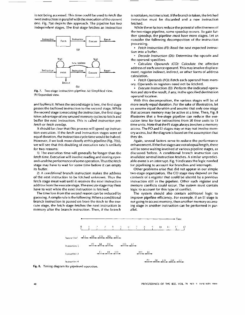
i s not being accessed. This time could be used to fetch the next instruction in parallel with theexecution of thecurrent one. Fig. 7(a) depicts this approach. The pipeline has two independent stages. The first stage fetches an instruction
Instruction Instruction Result Fetch - + Execute
Wait Wait New Address
I 1 Ins t ruc t ion4 I Ins t ruc t ion4 Execute 1 Result ~
w
Disc a r d
(b) Fig. 7. Two-stage instruction pipeline. (a) Simplified view. (b) Expanded view.
and buffers it. When the second stage is free, the first stage passes the buffered instruction to the second stage. While the second stage is executing the instruction, the first stage takes advantage of any unused memory cycles to fetch and buffer the next instruction. This i s called instruction pre- fetch or fetch overlap.
It should be clear that this process will speed up instruc- tion execution. If the fetch and instruction stages were of equal duration, the instruction cycle time would be halved. However, if we look more closely at this pipeline (Fig. 7(b)), we will see that this doubling of execution rate i s unlikely for two reasons:
1) The execution time will generally be longer than the fetch time. Execution will involve reading and storing oper- ands and the performanceof someoperation. Thus the fetch stage may have to wait for some time before it can empty its buffer.
2) A conditional branch instruction makes the address of the next instruction to be fetched unknown. Thus the fetch stage must wait until it receives the next instruction address from theexecute stage. Theexecute stage maythen have to wait while the next instruction i s fetched.
The time loss from the second reason can be reduced by guessing. A simple rule i s the following: When aconditional branch instruction is passed on from the fetch to the exe- cute stage, the fetch stage fetches the next instruction in memory after the branch instruction. Then, if the branch
i s not taken, no time is lost. If the branch i s taken, the fetched instruction must be discarded and a new instruction fetched.
While these factors reduce the potential effectiveness of the two-stage pipeline, some speedup occurs. To gain fur- ther speedup, the pipeline must have more stages. Let us consider the following decomposition of the instruction processing.
Fetch Instruction (FI): Read the next expected instruc- tion into a buffer. - Decode Instruction (DI): Determine the opcode and the operand specifiers.
Calculate Operands (CO): Calculate the effective address of each source operand. This may involve displace- ment, register indirect, indirect, or other forms of address calculation.
Fetch Operands (FO): Fetch each operand from mem- ory. Operands in registers need not be fetched.
Execute Instruction (€1): Perform the indicated opera- tion and store the result, if any, in the specified destination operand location.
With this decomposition, the various stages will be of more nearly equal duration. For the sake of illustration, let us assume equal duration and assume that only one stage that accesses memory may be active at a time. Then, Fig. 8 illustrates that a five-stage pipeline can reduce the exe- cution time for four instructions from 20 time units to 13 time units. Note that the FI stage always involves a memory access. The FO and E l stages may or may not involve mem- ory access, but the diagram is based on the assumption that they do.
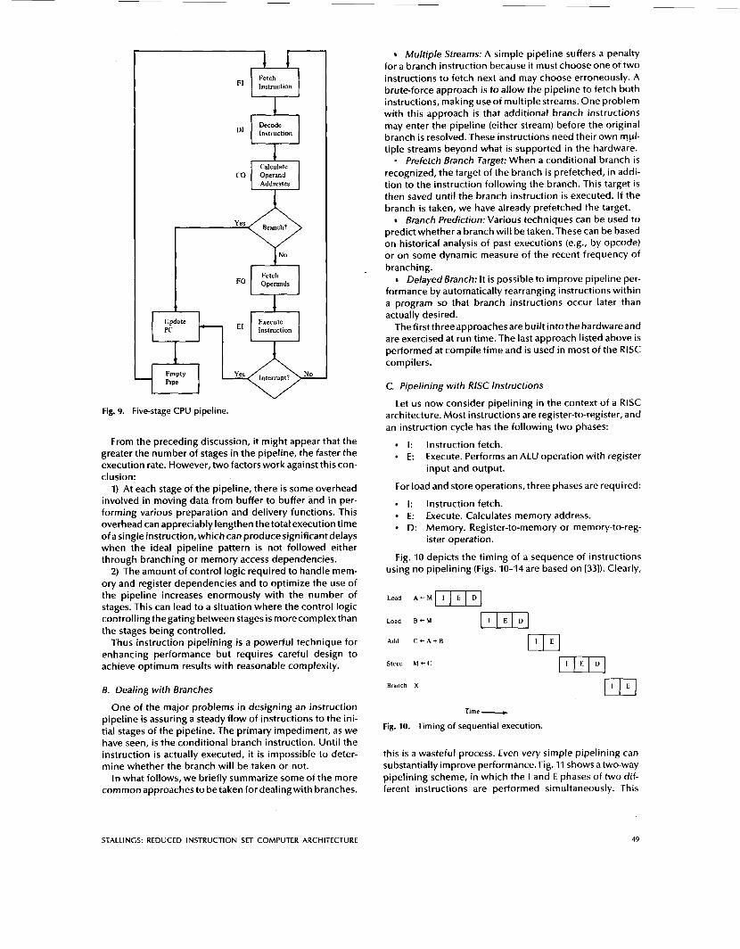
Again, several factors serve to reduce the performance enhancement. If the five stages are not of equal length, there will be some waiting involved at various pipeline stages, as discussed before. A conditional branch instruction can invalidate several instruction fetches. A similar unpredict- able event is an interrupt. Fig. 9 indicates the logic needed for pipelining to account for branches and interrupts.
Other problems arise that did not appear in our simple two-stage organization. The CO stage may depend on the contents of a register that could be altered by a previous instruction st i l l in the pipeline. Other such register and memory conflicts could occur. The system must contain logic to account for this type of conflict.
The system should also contain additional logic to improve pipeline efficiency. For example, if an El stage is not going to access memory, then another memory-access- ing stage in another instruction can be performed in par- allel.
0 I 2 3 4 5 6 7 8 Y I O I1 12 13 I I I I I I I I 1
Instruction 4
Fig. 8. Timing diagram for pipelined operation.
LI -
48 PROCEEDINGS OF THE IEEE. VOL. 7fi NO 1 I A N I I A R V ~ Q R R
I Calculate
I
Fetch Operands
1 :T 1 Exec; 1 Instruction
A I A
Fig. 9. Five-stage CPU pipeline.
From the preceding discussion, it might appear that the greater the number of stages in the pipeline, the faster the execution rate. However, two factors work against this con- clusion:
1) At each stage of the pipeline, there i s some overhead involved in moving data from buffer to buffer and in per- forming various preparation and delivery functions. This overhead can appreciably lengthen the total execution time of a single instruction, which can produce significant delays when the ideal pipeline pattern i s not followed either through branching or memory access dependencies.
2) The amount of control logic required to handle mem- ory and register dependencies and to optimize the use of the pipeline increases enormously with the number of stages. This can lead to a situation where the control logic controlling thegating between stages is morecomplex than the stages being controlled.
Thus instruction pipelining is a powerful technique for enhancing performance but requires careful design to achieve optimum results with reasonable complexity.
B. Dealing with Branches
One of the major problems in designing an instruction pipeline i s assuring a steady flow of instructions to the ini- tial stages of the pipeline. The primary impediment, as we have seen, i s the conditional branch instruction. Until the instruction i s actually executed, it i s impossible to deter- mine whether the branch will be taken or not.
In what follows, we briefly summarize some of the more common approaches to be taken for dealing with branches.
Multiple Streams: A simple pipeline suffers a penalty for a branch instruction because it must choose one of two instructions to fetch next and may choose erroneously. A brute-force approach is to allow the pipeline to fetch both instructions, making useof multiple streams. One problem with this approach is that additional branch instructions may enter the pipeline (either stream) before the original branch is resolved. These instructions need their own mul- tiple streams beyond what is supported in the hardware. - Prefetch Branch Target: When a conditional branch is recognized, the target of the branch is prefetched, in addi- tion to the instruction following the branch. This target is then saved until the branch instruction i s executed. If the branch is taken, we have already prefetched the target.
Branch Prediction: Various techniques can be used to predict whether a branch will be taken. These can be based on historical analysis of past executions (e.g., by opcode) or on some dynamic measure of the recent frequency of branching.
Delayed Branch: It i s possible to improve pipeline per- formance by automatically rearranging instructions within a program so that branch instructions occur later than actually desired.
The firstthreeapproaches are built intothe hardwareand are exercised at run time. The last approach listed above i s performed at compile time and is used in most of the RlSC compilers.
C. Pipelining with RlSC Instructions
Let us now consider pipelining in the context of a RlSC architecture. Most instructions are register-to-register, and an instruction cycle has the following two phases:
I: Instruction fetch. E: Execute. Performs an ALU operation with register
input and output.
For load and store operations, three phases are required:
I: Instruction fetch. E: Execute. Calculates memory address. D: Memory. Register-to-memory or memory-to-reg-
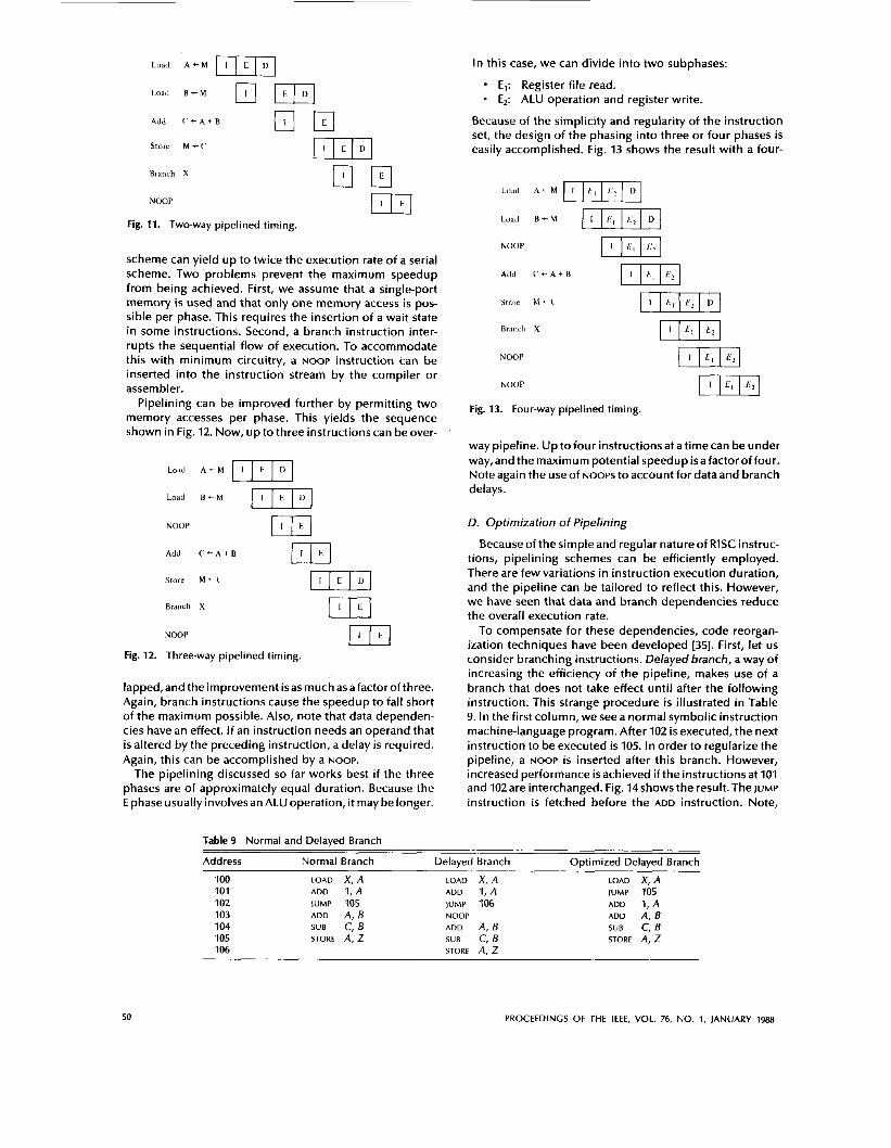
Fig. 10 depicts the timing of a sequence of instructions using no pipelining (Figs. 10-14 are based on [33]). Clearly,
ister operation.
Load A + M [ I I E I D J
Add C + A + B
Store M + C
Branch X
Time - Fig. 10. Timing of sequential execution.
this i s a wasteful process. Even very simple pipelining can substantially improve performance. Fig. 11 shows a two-way pipelining scheme, in which the I and E phases of two dif- ferent instructions are performed simultaneously. This
STALLINCS: REDUCED INSTRUCTION SET COMPUTER ARCHITECTURE 49
Load A - M ml Load B - M
Add C + A + B
Store M e ( '
Branch X
NOOP
El
Fig. 11. Two-way pipelined timing.
scheme can yield up to twice the execution rate of a serial scheme. Two problems prevent the maximum speedup from being achieved. First, we assume that a single-port memory is used and that only one memory access i s pos- sible per phase. This requires the insertion of a wait state in some instructions. Second, a branch instruction inter- rupts the sequential flow of execution. To accommodate this with minimum circuitry, a NOOP instruction can be inserted into the instruction stream by the compiler or assembler.
Pipelining can be improved further by permitting two memory accesses per phase. This yields the sequence shown in Fig. 12. Now, up to three instructions can be over-
Load A - M
Load B t M
NOOP
m Add C+-AtB
Storr M e(' [IIEID] Branch X
NOOP
Fig. 12. Three-way pipelined timing.
lapped,and theimprovement isas much asafactorofthree. Again, branch instructions cause the speedup to fall short of the maximum possible. Also, note that data dependen- cies have an effect. If an instruction needs an operand that is altered by the preceding instruction, a delay i s required. Again, this can be accomplished by a NOOP.
The pipelining discussed so far works best if the three phases are of approximately equal duration. Because the E phase usually involves an ALU operation, it may be longer.
In this case, we can divide into two subphases:
E,: Register file read. E,: ALU operation and register write.
Because of the simplicity and regularity of the instruction set, the design of the phasing into three or four phases is easily accomplished. Fig. 13 shows the result with a four-
Lood A + M
Load B + M -1 NOOP -1 Add C + A + B -1 Store M + C ml Branch X WI NOOP m1 NOOP
Fig. 13. Four-way pipelined timing.
way pipeline. Up to four instructions at a time can be under way,and themaximum potential speedup isafactoroffour. Note again the use of NOOPS to account for data and branch delays .
D. Optimization of Pipelining
Because of the simple and regular nature of RISC instruc- tions, pipelining schemes can be efficiently employed. There are few variations in instruction execution duration, and the pipeline can be tailored to reflect this. However, we have seen that data and branch dependencies reduce the overall execution rate.
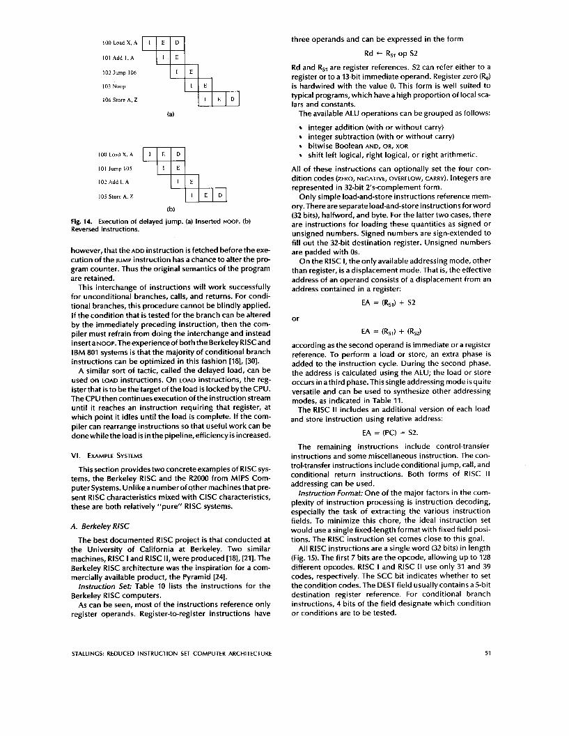
To compensate for these dependencies, code reorgan- ization techniques have been developed [35]. First, let us consider branching instructions. Delayed branch, a way of increasing the efficiency of the pipeline, makes use of a branch that does not take effect until after the following instruction. This strange procedure is illustrated in Table 9. In the first column, we seea normal symbolic instruction machine-language program. After 102 is executed, the next instruction to be executed is 105. In order to regularize the pipeline, a NOOP i s inserted after this branch. However, increased performance is achieved if the instructions at 101 and 102 are interchanged. Fig. 14 shows the result. The JUMP
instruction is fetched before the ADD instruction. Note,
Table 9 Normal and Delayed Branch
Address Normal Branch Delayed Branch Optimized Delayed Branch
100 101 102 103 104 105 106
LOAD X , A ADD 1, A IUMP 105 ADD A, B
STORE A, z SUB C, B
LOAD x, A ADD 1 , A JUMP 106 NOOP ADD A, B
STORE A, z S U B C, B
LOAD X , A JUMP 105 ADD 1, A ADD A , 6
STORE A, z S U B C, B
50 PROCEEDINGS OF THE IEEE, VOL. 76, NO. 1, JANUARY 1988
IO0 Load X, A
101 Add I . A
102 Jump 106
103 Noop
106 Store A, Z
(a)
100 Load X. A
101 lump 105
102 Add 1. A
105 Store A. Z
, D
(b) Fig. 14. Execution of delayed jump. (a) Inserted NOOP. (b) Reversed instructions.
however, that the ADD instruction i s fetched before the exe- cution of the JUMP instruction has a chance to alter the pro- gram counter. Thus the original semantics of the program are retained.
This interchange of instructions will work successfully for unconditional branches, calls, and returns. For condi- tional branches, this procedure cannot be blindly applied. If the condition that is tested for the branch can be altered by the immediately preceding instruction, then the com- piler must refrain from doing the interchange and instead inserta NooP.Theexperienceof both the Berkeley RlSCand IBM 801 systems is that the majority of conditional branch instructions can be optimized in this fashion [18], [30].
A similar sort of tactic, called the delayed load, can be used on LOAD instructions. On LOAD instructions, the reg- ister that is to be the’target of the load is locked by the CPU. The CPU then continues execution of the instruction stream until it reaches an instruction requiring that register, at which point it idles until the load is complete. If the com- piler can rearrange instructions so that useful work can be donewhiletheload is in the pipeline, efficiencyis increased.
VI. EXAMPLE SYSTEMS
This section provides two concrete examples of RlSC sys- tems, the Berkeley RlSC and the R2000 from MIPS Com- puter Systems. Unlikeanumberofother machinesthat pre- sent RlSC characteristics mixed with ClSC characteristics, these are both relatively “pure” RlSC systems.
A. Berkeley RlSC
The best documented RlSC project is that conducted at the University of California at Berkeley. Two similar machines, RlSC I and RlSC II, were produced [18], [21]. The Berkeley RlSC architecture was the inspiration for a com- mercially available product, the Pyramid [24].
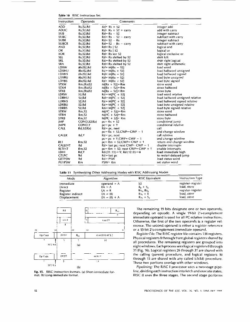
Instruction Set: Table 10 lists the instructions for the Berkeley RlSC computers.
As can be seen, most of the instructions reference only register operands. Register-to-register instructions have
three operands and can be expressed in the form
Rd + Rsl OP S2
Rd and Rsl are register references. S2 can refer either to a register or to a 13-bit immediate operand. Register zero (R,) is hardwired with the value 0. This form is well suited to typical programs, which have a high proportion of local sca- lars and constants.
The available ALU operations can be grouped as follows:
integer addition (with or without carry) integer subtraction (with or without carry) bitwise Boolean AND, OR, XOR
shift left logical, right logical, or right arithmetic.
All of these instructions can optionally set the four con- dition codes (ZERO, NEGATIVE, OVERFLOW, CARRY). Integers are represented in 32-bit 2’s-complement form.
Only simple load-and-store instructions reference mem- ory. There are separate load-and-store instructions forword (32 bits), halfword, and byte. For the latter two cases, there are instructions for loading these quantities as signed or unsigned numbers. Signed numbers are sign-extended to fill out the 32-bit destination register. Unsigned numbers are padded with Os.
On the RlSC I , the only available addressing mode, other than register, is a displacement mode. That is, the effective address of an operand consists of a displacement from an address contained in a register:
EA = (RSI) + S2
or
EA = (RsJ + (RsJ
according as the second operand is immediate or a register reference. To perform a load or store, an extra phase is added to the instruction cycle. During the second phase, the address is calculated using the ALU; the load or store occurs in athird phase. This single addressing mode isquite versatile and can be used to synthesize other addressing modes, as indicated in Table 11.
The RlSC II includes an additional version of each load and store instruction using relative address:
EA = (PC) = S2.
The remaining instructions include control-transfer instructions and some miscellaneous instruction. The con- trol-transfer instructions include conditional jump, call, and conditional return instructions. Both forms of RlSC I I addressing can be used.
Instruction Format: One of the major factors in the com- plexity of instruction processing is instruction decoding, especially the task of extracting the various instruction fields. To minimize this chore, the ideal instruction set would use a single fixed-length format with fixed field posi- tions. The RlSC instruction set comes close to this goal.
All RlSC instructions are a single word (32 bits) in length (Fig. 15). The first 7 bits are the opcode, allowing up to 128 different opcodes. RISC I and RlSC II use only 31 and 39 codes, respectively. The SCC bit indicates whether to set the condition codes. The DEST field usually contains a 5-bit destination register reference. For conditional branch instructions, 4 bits of the field designate which condition or conditions are to be tested.
STALLINCS: REDUCED INSTRUCTION SET COMPUTER ARCHITECTURE 51
~
Table 10 RlSC Instruction Set
I
Instruction Operands Comments
Op Code DLST
7 1 5 1 s
ADD ADDC SUB SUBC SUBR SUBCR AND OR XOR SLL SRL SRA LDXW LDXHU LDXHS LDXBU LDYBS STXW STXH STXB LDRW LDRHU LDRHS LDRBU LDRBS STRW STRH STRB JMP JMPR CALL
CALLR
RET CALLINS RETINT LDHl GTLPC GETPSW PUTPSW
4, shortSOII K ( ’ t 2
14
Rs,S2,Rd Rs,S2,Rd Rs,SZ,Rd Rs,S2,Rd Rs,S2,Rd Rs,S2,Rd Rs,S2,Rd Rs,S2,Rd Rs,SZ,Rd Rs,S2,Rd Rs,S2,Rd Rs,S2,Rd (Rx)SZ,Rd (Rx)S2,Rd (Rx)SZ,Rd (Rx)S2,Rd (Rx)S2,Rd Rm,(Rx)S2 Rm,(Rx)S2 Rm,(Rx)S2 S2,Rd S2,Rd S2,Rd S2,Rd S2,Rd Rm,S2 Rm,S2 Rm,S2 COND,S2(Rx) COND,Y Rd,SZ(Rx)
Rd,Y
Rm,S2 Rd Rm,S2 Rd,Y Rd Rd Rm
o p (‘ode
RdeRs + S2 RdtRs + S2 + carry
RdtRs - S2 - carry
Rd tS2 - Rs - carry RdtRs 1 S2 RdtRs I S2 R d t Rs xor S2 Rd-Rs shifted by S2 Rd-Rs shifted by S2 RdtRs shifted by S2 Rd+-M[Rx + S2] Rd+-M[Rx + S2] RdtM[Rx + S2] RdtM[Rx + S2] RdtM[Rx + S2] M[Rx + S2]-Rm M[Rx + SZI-Rm M[Rx + S2]-Rm Rd+-M[PC + S21 Rd-M[PC + S2] Rd+-M[PC + S2] RdtM[PC + SZ] Rd-M[PC + S2] M[PC + S2]+Rm M[PC + S2]+Rm M[PC + S2ItRm p c t R x + S2
Rdtpc , next
Rd-pc, next
p c t R m + SZ,CWP+CWP + 1 Rdt last pc; next CWPtCWP - 1 pc-Rm + S2; next CWPeCWP + 1 Rd( 31 : 13) Rd-last pc RdtPSW PSWtRm
RdtRs - S2
RdtS2 - RS
pc+pc + Y
~ c ~ R x + S2,CWPtCWP - 1
p c t p c + Y,CWP+-CWP - 1
Y; Rd( 12: 0 ) t O
D f S T irnrnlLl
integer add add with carry integer subtract subtract with carry integer subtract subtract with carry logical and logical or logical exclusive or shift left shift right logical shift right arithmetic load word load halfword unsigned load halfword signed load byte unsigned load byte signed store word store halfword store byte load word relative load halfword unsigned relative load halfword signed relative load byte unsigned relative load byte signed relative store word store halfword store byte conditional jump conditional relative call and change window call relative and change window return and change window disable interrupts enable interrupts load immediate high to restart delayed jump load status word set status word
Table 11 Synthesizing Other Addressing Modes with RlSC Addressing Modes
Mode Algorithm RlSC Equivalent Instruction Type ~ ~~
I mmediate Direct Register Register indirect Displacement
operand = A EA = A EA = R EA = (R) EA = (R) + A
register-register load, store register-register load, store load, store
The remaining 19 bits designate one o r t w o operands, depending on opcode. A single 19-bit 2’s-complement immediate operand is used fo r all PC-relative instructions. Otherwise, the first o f the t w o operands i s a register ref- erence. The second operand is either a register reference or a 13-bit 2’s-complement immediate operand.
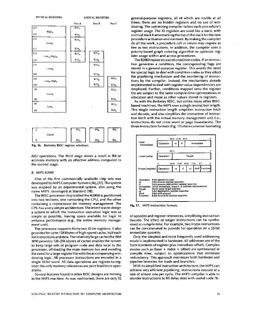
RegisterFi/e:The RlSC register f i le contains 138 registers. Physical registers 0 through 9 are global registers shared by all procedures. The remaining registers are grouped in to eight windows. Each process sees logical registers Othrough 31 (Fig. 16). Logical registers 26 through 31 are shared w i th the cal l ing (parent) procedure, and logical registers 10 through 15 are shared w i t h any called (child) procedure. These t w o port ions overlap w i t h other windows.
Pipelining: The RlSC I processor uses a two-stage pipe- line, d iv id ing each instruct ion in to fetch and execute states. RlSC II uses the three stages. The second stage performs
52 PROCEEDINGS OF THE IEEE. VOL. 76. NO. 1 I A N l l A R V l Q R R
PHYSICAL REGISTERS LOGICAL REGISTERS
Proc A Proc B Roc c
R31,
R26,
R25,
R10,
- R31,
R?6,
R25, -
R16,
R15,
R10,
-
-
Fig. 16. Berkeley RlSC register windows.
ALU operations. The third stage stores a result in Rd or accesses memory with an effective address computed in the second stage.
B. MIPS R2000
One of the first commercially available chip sets was developed by MIPS Computer Systems [36], [37l. The system was inspired by an experimental system, also using the name MIPS, developed at Stanford [38].
The RlSC processor chip (called the R2000) is partitioned into two sections, one containing the CPU, and the other containing a coprocessor for memory management. The CPU has averysimplearchitecture.The intentwas todesign a system in which the instruction execution logic was as simple as possible, leaving space available for logic to enhance performance (e.g., the entire memory manage- ment unit).
The processor supports thirty-two 32-bit registers. It also provides for up to 128 kbytes of high-speed cache, half each for instructionsand data.The relativelylargecache(the IBM 3090 provides 128-256 kbytes of cache) enables the system to keep large sets of program code and data local to the processor, off-loading the main memory bus and avoiding the need fora large registerfilewith theaccompanyingwin- dowing logic. All processor instructions are encoded in a single 32-bit word. All data operations are register-to-reg- ister; the only memory references are pure loadlstore oper- ations.
Several features found in other RlSC designs are missing in the MIPS machine. As was mentioned, there are only 32
general-purpose registers, all of which are visible at all times; there are no hidden registers and no use of win- dowing. The optimizing compiler tailors each procedure’s register usage. The 32 registers are used like a stack, with avirtual stackframemarkingthetopof thestackforthenew procedure activation environment. By making the compiler do all the work, a procedure call or return may require as few as two instructions. In addition, the compiler uses a priority-based graph coloring algorithm to optimize reg- ister usage within and across procedures.
The R2000 makes no use of condition codes. If an instruc- tion generates a condition, the corresponding flags are stored in a general-purpose register. This avoids the need for special logic to deal with condition codes as they affect the pipelining mechanism and the reordering of instruc- tions by the compiler. Instead, the mechanisms already implemented to deal with register-value dependencies are employed. Further, conditions mapped onto the register file are subject to the same compile-time optimizations in allocation and reuse as other values stored in registers.
As with the Berkeley RISC, but unlike many other RISC- based machines, the MIPS uses a single instruction length. This single instruction length simplifies instruction fetch and decode, and also simplifies the interaction of instruc- tion fetch with the virtual memory management unit (i.e., instructions do not cross word or page boundaries). The three instruction formats (Fig. 17) share common formating
31 2625 2120 1615 0
[-type (immediate) Operation rs rt Immediate I 31 2625 2120 1615 1110 6 5 0
R-type (register) Operation rs rt rd shift F.unction
Operation 6-bit operation code 5-bit source register specifier 5-bit sourceldestination register specifier
Immediate 16-bit immediate. branch or address displacement Target 26-bit jump target address rd 5-bit destination register specifier Shift %bit shift amount Function &bit ALUlshift function specifier
Fig. 17. MIPS instruction formats.
of opcodes and register references, simplifying instruction decode. The effect of longer instructions can be synthe- sized at compile time. For example, two I-type instructions can be concatenated to provide for operation on a 32-bit immediate quantity.
Only the simplest and most frequently used addressing mode is implemented in hardware. All addresses are of the form (contents of register plus immediate offset). Complex modes such as (base + index + offset) are synthesized in compile time, subject to optimizations that eliminate redundancy. This approach minimizes both hardware and pipeline latencies for loads and branches.
With its simplified instruction architecture, the MIPS can achieve very efficient pipelining. Instructions execute at a rate of almost one per cycle. The MIPS compiler i s able to reorder instructions to fill delay slots with useful code 70-
STALLING: REDUCED INSTRUCTION SET COMPUTER ARCHITECTURE 53
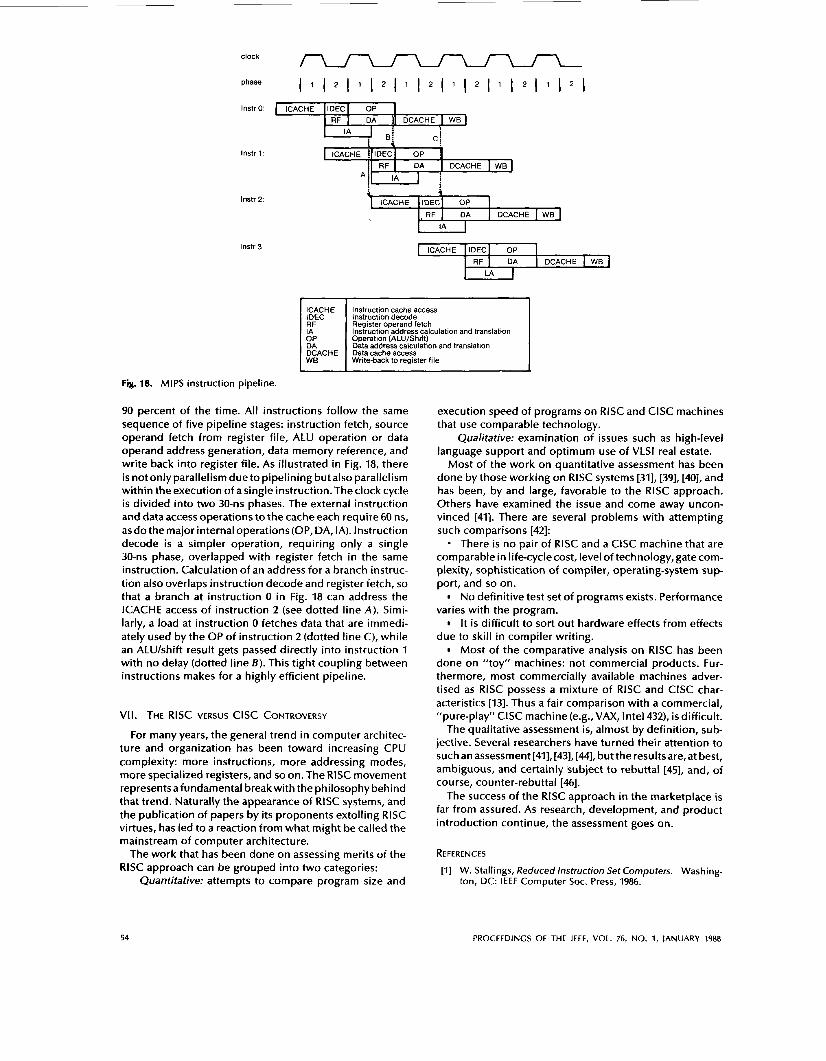
clock
CACHE
DhaSe
IDECI OP 1 RF I DA I DCACHE I WB
Instro: CACHE ( IDEC~ OP 1 I RF I DA ]I DCACHE I WB
‘4, lnstr 1:
lnstr 2:
lnstr 3:
Fig. 18. MIPS instruction pipeline.
4 CACHE ~ I D E C ~ OP I
RF I DA I DCACHE I WB
ICACHE IDEC RF IA OP DA DCACHE WB
Instruction cache access Instruction decode Register operand fetch Instruction address calculation and translation Operation (ALU/Shift) Data address calculation and translation Data cache access Write-back to register file
90 percent of the time. All instructions follow the same sequence of five pipeline stages: instruction fetch, source operand fetch from register file, ALU operation or data operand address generation, data memory reference, and write back into register file. As illustrated in Fig. 18, there i s not onlyparallelism dueto pipelining but also parallelism within the execution of a single instruction. The clock cycle i s divided into two 30-11s phases. The external instruction and data access operations to the cache each require 60 ns, as do the major internal operations (OP, DA, IA). Instruction decode is a simpler operation, requiring only a single 30-ns phase, overlapped with register fetch in the same instruction. Calculation of an address for a branch instruc- tion also overlaps instruction decode and register fetch, so that a branch at instruction 0 in Fig. 18 can address the ICACHE access of instruction 2 (see dotted line A). Simi- larly, a load at instruction 0 fetches data that are immedi- ately used by the OP of instruction 2 (dotted line C), while an ALUlshift result gets passed directly into instruction 1 with no delay (dotted line B ) . This tight coupling between instructions makes for a highly efficient pipeline.
VII. THE RlSC VERSUS ClSC CONTROVERSY
For many years, the general trend in computer architec- ture and organization has been toward increasing CPU complexity: more instructions, more addressing modes, more specialized registers, and so on. The RlSC movement represents afundamental breakwith the philosophy behind that trend. Naturally the appearance of RlSC systems, and the publication of papers by its proponents extolling RlSC virtues, has led to a reaction from what might be called the mainstream of computer architecture.
The work that has been done on assessing merits of the RlSC approach can be grouped into two categories:
Quantitative: attempts to compare program size and
execution speed of programs on RlSC and ClSC machines that use comparable technology.
Qualitative: examination of issues such as high-level language support and optimum use of VLSl real estate.
Most of the work on quantitative assessment has been done by those working on RlSC systems [311, [391, [40], and has been, by and large, favorable to the RlSC approach. Others have examined the issue and come away uncon- vinced 1411. There are several problems with attempting such comparisons [42]: - There is no pair of RlSC and a ClSC machine that are comparable in life-cycle cost, level of technology, gatecom- plexity, sophistication of compiler, operating-system sup- port, and so on.
No definitive test set of programs exists. Performance varies with the program.
It is difficult to sort out hardware effects from effects due to skill in compiler writing.
Most of the comparative analysis on RlSC has been done on “toy” machines: not commercial products. Fur- thermore, most commercially available machines adver- tised as RlSC possess a mixture of RlSC and ClSC char- acteristics [13]. Thus a fair comparison with a commercial, “pure-play“ ClSC machine (e.g.,VAX, Intel 432), i s difficult.
The qualitative assessment is, almost by definition, sub- jective. Several researchers have turned their attention to such an assessment [41], [43], [441, but the resultsare, at best, ambiguous, and certainly subject to rebuttal [45], and, of course, counter-rebuttal [46].
The success of the RlSC approach in the marketplace is far from assured. As research, development, and product introduction continue, the assessment goes on.
REFERENCES
[I] W. Stallings, Reduced lnstruction Set Computers. Washing- ton, DC: IEEE Computer Soc. Press, 1986.
54 PROCEEDINGS OF THE IEEE, VOL. 76, NO. 1, JANUARY 1988
R. Weiss, “RISC processors: The new wave in computer sys- tems,” Comput. Des., pp. 53-73, May 15,1987. C. Bruno and S. Brady, “The RlSC factor,” Datamation, pp. y-DD, June 1,1986. J. Moussourisetal.,“ACMOS RlSC processorwith integrated system functions,” in froc. Compcon Spring 86 (Mar. 1986),
L. Neff,”Clipper” microprocessor architecture overview,” in froc. Compcon Spring 86 (Mar. 1986), pp. 191-195. F. Waters, Ed., ISM RT Personal Computer Technology, IBM
E. Basart, “RISC design streamlines high-power CPUs,” Com- put. Des., pp. 119-122, July 1, 1985. S. Cannes, ”Back-to-basics computers with sports-car speed,” Fortune, pp. 98-101, Sept. 30, 1985. M. Miller, “Simplicity i s focus in efforts to increase computer power,” The Wall Street]., p. 17, Aug. 23, 1985. S. Ohr, ”RISC machines,” Hectron. Des., pp. 175-190, Jan. IO, 1985. M. Seither, ”Pyramid challenges DEC with RlSC supermini,”
R. Bernhard, “RISCs-Reduced instruction set computers- make leap,” Syst. Software, pp. 81-84, Dec. 1984. N. Mokhoff,”New RlSC machinesappearas hybridswith both RlSC and ClSC features,” Comput. Des., pp. 22-25, Apr. 1, 1986. J. Birnbaum and W. Worley, “Beyond RISC: High-precision architecture,” in froc. Compcon Spring 86 (Mar. 1986), pp. 40-47. J. Browne, “Understanding execution behavior of software systems,” Computer, vol. 17, pp. 83-87, July 1984. D. Knuth, ”An empirical study of FORTRAN brograms,” Soft- ware Practice Exper., vol. 1, pp. 105-133, 1971. A. Tanenbaum, ”Implications of structured programming for machine architecture,” Commun. ACM, pp. 237-246, Mar. 1978. D. Patterson and C. Sequin, “A VLSI RISC,” Computer, pp. 8-22, Sept. 1982. T. Huck, “Comparative analysis of computer architectures,” Stanford Univ. Tech. Rep. 83-243, May 1983. A. Lunde, “Empirical evaluation of some features of instruc- tion set processor architectures,” Commun. ACM, pp. 143- 153, Mar. 1972. M. Katevenis, ”Reduced instruction set computer architec- tures for VLSI,” Ph.D. dissertation, Computer Sci. Dep., Univ. of California at Berkeley, Oct. 1983. Reprinted by MIT Press, Cambridge, MA, 1985. D. Patterson, “Reduced instruction set computers,” Com- mun. ACM, pp. 8-21, Jan. 1985. Y. Tamir and C. Sequin, “Strategies for managing the register file in RISC,” /€€€Trans. Comput.,vol. C-30, pp. 977-988, Nov. 1983. R. Ragan-Kelley and R. Clark, “Applying RlSC theoryto a large computer,” Comput. Des., pp. 191-198, Nov. 1983. W. Stallings, Computer Organization and Architecture. New York, NY: Macmillan, 1987. G. Chaitin, “Register allocation and spilling via graph col- oring,” in froc. SlGfLAN Symp. on Compiler Construction (June 1982), pp. 98-105. F. Chow, M. Himelstein, E. Killian, and L. Weber, “Engi- neering a RlSC compiler system,” in froc. Compcon Spring 86 (Mar. 1986), pp. 132-137. D. Coutant, C. Hammond, and J. Kelley, “Compilers for the new generation of Hewlett-Packard Computers,” in froc. Compcon Spring 86 (Mar. 1986), pp. 182-195. J. Hennessy eta/., “Hardwarekoftware tradeoffs for increased performance,” in froc. Symp. on Architectural Support for Programming Languages and Operating Systems, pp. 2-11, Mar. 1982.
pp. 126-131.
Publ. SA23-1057, 1986.
Mini-Micro Syst., pp. 33-36, Aug. 1985.
[30] G. Radin, “The 801 minicomputer,” ISM /. Res. Devel., pp. 237-246, May 1983.
[31] D. Patterson and R. Piepho, “Assessing RlSCs in high-level language support,” /€€E Micro, vol. 2, pp. 9-18, Nov. 1982.
[32] C. Myers, “The evaluation of expressions in a storage-to-stor- age architecture,” Comput. Arch. News, June 1978.
[33] R. Sherburne, ”Processor design tradeoffs in VLSI,” Ph.D. dis- sertation, Rep. UCBKSD 84/173, Univ. of California at Berke- ley, Apr. 1984.
[34] D. Fitzpatrick eta/., “A RlSCy approach to VLSI,” VLSl Des., pp. 14-20,4th Quarter, 1981.
[35] J. Hennessy and T. Gross, “Postpass code optimization of pipeline constraints,” ACM Trans. Programming Languages Syst., July 1983.
[36] C. Rowen et al., “RISC VLSI design for system-level perfor- mance,” VLSl Syst. Des., Mar. 1986.
[37l J. Moussouriseta/.,”ACMOS RlSC processorwith integrated system functions,” in froc. COMfCONSpring86 (Mar. 1986),
[38] J. L. Hennessy, “VLSI processor architecture,” /E€€ Trans. Comput., vol. C-33, pp. 1221-1246, Dec. 1984.
[39] J. Heath, ”Re-evaluation of RlSC I , ” Comput. Arch. News, Mar. 1984.
[40] D. Patterson, “RISC watch,” C o n p t . Arch. News, Mar. 1984. [41] R. P. Colwell, C. Y. Hitchcock, E. D. Jensen, H. M. B. Brinkley-
Sprunt, and C. P. Kollar, “Instruction sets and beyond: Com- puters, complexity and controversy,” Computer, vol. 18, pp. 8-19, Sept. 1985.
[42] 0. Serlin, “MIPS, dhrystones, and other tales,” Datamation, pp. 112-118, June 1, 1986.
[43] R. Bernhard, ”More hardware means less software,” / € € E Spectrum, December 1981.
[44] P. Wallich, ”Toward simpler, faster computers.” /E€€ Spec-
[45] D. Patterson and J. Hennessy, ”Comments, with reply on ‘Computers, complexity, and controversy,” by R. P. Colwell, et al., Computer, vol. 18, pp. 142-143, Nov. 1985.
[46] R. Colwell, C. Hitchcock, E. Jensen, and H. Sprunt, “More controversy about ’computers, complexity, and contro- versy,”’ Computer, p. 93, Dec. 1985.
pp. 126-131.
trum, vol. 22, pp. 38-45, Aug. 1985.
William Stallings (Senior Member, IEEE) received the B.S. degree in electrical engi- neering from Notre Dame University, Notre Dame, IN, and the Ph.D. degree in com- puter science from theMassachusetts Insti- tute of Technology, Cambridge, MA.
He is an independent consultant and president of ComplComm Consulting, London, England. He i s also a frequent lec- turerand theauthor of numerous technical papers and eleven books in the fields of data
communications and computer science, including Computer Organization andArchitecture (New York, NY: Macmillan, 1987) and Data and Computer Communications, Second Edition (New York, NY: Macmillan, 1988). His clients have included the Government of India, the International Monetary Fund, the National Security Agency, IBM, and Honeywell. Prior to forming his own consulting firm, he was Vice President of CSM Corp., a firm specializing in data processing and data communications for the health-care industry. He was also Director of Systems analysis and design for CTEC, Inc., a firm specializing in command, control, and com- munications systems.
STALLINCS: REDUCED INSTRUCTION SET COMPUTER ARCHITECTURE 55