Embed Size (px)
Citation preview

ibm.com/redbooks Redpaper
Front cover
The LTO Ultrium Primer for IBM iSeries Customers
Susan PowersJuergen Ginter
Jana JamsekDidier Mauger
Gain an understanding of 358x storage for the iSeries server
Install, tailor, and configure LTO for OS/400 and configure OS/400 for LTO
Learn about LTO tape drive positioning against other storage options


International Technical Support Organization
The LTO Ultrium Primer for IBM ~ iSeries Customers
October 2002

© Copyright International Business Machines Corporation 2002. All rights reserved.Note to U.S. Government Users Restricted Rights -- Use, duplication or disclosure restricted by GSA ADP Schedule Contract with IBMCorp.
First Edition (October 2002)
This edition applies to Version 5, Release 2 of OS/400 (product number 5722-SS1).
Note: Before using this information and the product it supports, read the information in “Notices” on page vii.

Contents
Notices . . . . . . . . . . . . . . . . . . . . . . . . . . . . . . . . . . . . . . . . . . . . . . . . . . . . . . . . . . . . . . . . . viiTrademarks . . . . . . . . . . . . . . . . . . . . . . . . . . . . . . . . . . . . . . . . . . . . . . . . . . . . . . . . . . . . . viii
Preface . . . . . . . . . . . . . . . . . . . . . . . . . . . . . . . . . . . . . . . . . . . . . . . . . . . . . . . . . . . . . . . . . ixThe team that wrote this Redpaper . . . . . . . . . . . . . . . . . . . . . . . . . . . . . . . . . . . . . . . . . . . . ixBecome a published author . . . . . . . . . . . . . . . . . . . . . . . . . . . . . . . . . . . . . . . . . . . . . . . . . . .xComments welcome. . . . . . . . . . . . . . . . . . . . . . . . . . . . . . . . . . . . . . . . . . . . . . . . . . . . . . . . .x
Chapter 1. An introduction to LTO for the iSeries literate . . . . . . . . . . . . . . . . . . . . . . . . 11.1 LTO technology overview . . . . . . . . . . . . . . . . . . . . . . . . . . . . . . . . . . . . . . . . . . . . . . . . 21.2 IBM LTO tape family product overview . . . . . . . . . . . . . . . . . . . . . . . . . . . . . . . . . . . . . . 2
1.2.1 IBM LTO tape and library models . . . . . . . . . . . . . . . . . . . . . . . . . . . . . . . . . . . . . . 31.2.2 358x capacities . . . . . . . . . . . . . . . . . . . . . . . . . . . . . . . . . . . . . . . . . . . . . . . . . . . . 6
1.3 Attachment options for the iSeries server . . . . . . . . . . . . . . . . . . . . . . . . . . . . . . . . . . . . 71.3.1 SCSI attachment . . . . . . . . . . . . . . . . . . . . . . . . . . . . . . . . . . . . . . . . . . . . . . . . . . . 71.3.2 Fibre attachment . . . . . . . . . . . . . . . . . . . . . . . . . . . . . . . . . . . . . . . . . . . . . . . . . . . 71.3.3 LTO attachment support . . . . . . . . . . . . . . . . . . . . . . . . . . . . . . . . . . . . . . . . . . . . . 7
1.4 Tape consolidation . . . . . . . . . . . . . . . . . . . . . . . . . . . . . . . . . . . . . . . . . . . . . . . . . . . . . 81.4.1 Sharing an IBM UltraScalable Tape Library using partitioning . . . . . . . . . . . . . . . . 81.4.2 Sharing an LTO device using switches . . . . . . . . . . . . . . . . . . . . . . . . . . . . . . . . . . 8
1.5 Future direction of LTO for the iSeries customer . . . . . . . . . . . . . . . . . . . . . . . . . . . . . . 91.6 Sample customer implementations . . . . . . . . . . . . . . . . . . . . . . . . . . . . . . . . . . . . . . . . 10
1.6.1 Small customer environment: Single host and LTO Ultrium tape with one drive . 101.6.2 Medium customer environment: Single host and LTO Ultrium tape with one or more
drives . . . . . . . . . . . . . . . . . . . . . . . . . . . . . . . . . . . . . . . . . . . . . . . . . . . . . . . . . . 111.6.3 Large customer environment: Several iSeries hosts (single host platform) and the
3583 Tape Library. . . . . . . . . . . . . . . . . . . . . . . . . . . . . . . . . . . . . . . . . . . . . . . . . 121.6.4 Large customer environment: Multihost platform with logical libraries and 3584 Tape
Library. . . . . . . . . . . . . . . . . . . . . . . . . . . . . . . . . . . . . . . . . . . . . . . . . . . . . . . . . . 13
Chapter 2. An introduction to iSeries server for the LTO literate . . . . . . . . . . . . . . . . . 152.1 Brief description of the IBM eServer iSeries server. . . . . . . . . . . . . . . . . . . . . . . . . . . . 16
2.1.1 iSeries architecture . . . . . . . . . . . . . . . . . . . . . . . . . . . . . . . . . . . . . . . . . . . . . . . . 162.1.2 iSeries software . . . . . . . . . . . . . . . . . . . . . . . . . . . . . . . . . . . . . . . . . . . . . . . . . . 172.1.3 Other important features of OS/400 and iSeries servers . . . . . . . . . . . . . . . . . . . 18
2.2 iSeries servers . . . . . . . . . . . . . . . . . . . . . . . . . . . . . . . . . . . . . . . . . . . . . . . . . . . . . . . 192.3 Sample implementation scenarios . . . . . . . . . . . . . . . . . . . . . . . . . . . . . . . . . . . . . . . . 20
Chapter 3. iSeries external tape storage and save and restore case scenarios . . . . . 233.1 Save and restore test scenarios . . . . . . . . . . . . . . . . . . . . . . . . . . . . . . . . . . . . . . . . . . 24
3.1.1 3570, 3575, and 3590 external tape devices . . . . . . . . . . . . . . . . . . . . . . . . . . . . 253.1.2 IBM Magstar MP 3570 Tape Cassette Subsystem . . . . . . . . . . . . . . . . . . . . . . . . 273.1.3 Magstar MP (Multipurpose) 3575 Tape Library Dataserver . . . . . . . . . . . . . . . . . 283.1.4 IBM 3590 High Performance Tape Subsystem Models E/H1A and E11/H11. . . . 30
3.2 Using ESS FlashCopy to reduce the time to save . . . . . . . . . . . . . . . . . . . . . . . . . . . . 32
Chapter 4. Planning for Ultrium external tape devices . . . . . . . . . . . . . . . . . . . . . . . . . 334.1 Description of physical planning requirements . . . . . . . . . . . . . . . . . . . . . . . . . . . . . . . 344.2 iSeries prerequisites for the IBM LTO . . . . . . . . . . . . . . . . . . . . . . . . . . . . . . . . . . . . . . 34
© Copyright IBM Corp. 2002. All rights reserved. iii

4.2.1 Hardware prerequisites . . . . . . . . . . . . . . . . . . . . . . . . . . . . . . . . . . . . . . . . . . . . . 344.2.2 Software prerequisites . . . . . . . . . . . . . . . . . . . . . . . . . . . . . . . . . . . . . . . . . . . . . 35
4.3 Performance considerations . . . . . . . . . . . . . . . . . . . . . . . . . . . . . . . . . . . . . . . . . . . . . 364.4 Related services . . . . . . . . . . . . . . . . . . . . . . . . . . . . . . . . . . . . . . . . . . . . . . . . . . . . . . 36
Chapter 5. LTO media . . . . . . . . . . . . . . . . . . . . . . . . . . . . . . . . . . . . . . . . . . . . . . . . . . . . 375.1 Media considerations and requirements . . . . . . . . . . . . . . . . . . . . . . . . . . . . . . . . . . . . 38
5.1.1 Benefits of using the Ultrium format . . . . . . . . . . . . . . . . . . . . . . . . . . . . . . . . . . . 385.1.2 High data transfer rate . . . . . . . . . . . . . . . . . . . . . . . . . . . . . . . . . . . . . . . . . . . . . 385.1.3 Wide range of applications . . . . . . . . . . . . . . . . . . . . . . . . . . . . . . . . . . . . . . . . . . 385.1.4 Cartridge memory . . . . . . . . . . . . . . . . . . . . . . . . . . . . . . . . . . . . . . . . . . . . . . . . . 385.1.5 Reliability. . . . . . . . . . . . . . . . . . . . . . . . . . . . . . . . . . . . . . . . . . . . . . . . . . . . . . . . 395.1.6 Reduced costs . . . . . . . . . . . . . . . . . . . . . . . . . . . . . . . . . . . . . . . . . . . . . . . . . . . 39
5.2 Ultrium tape media . . . . . . . . . . . . . . . . . . . . . . . . . . . . . . . . . . . . . . . . . . . . . . . . . . . . 395.2.1 Migrating to the LTO from other iSeries tape drives . . . . . . . . . . . . . . . . . . . . . . . 405.2.2 Using BRMS to migrate your data. . . . . . . . . . . . . . . . . . . . . . . . . . . . . . . . . . . . . 405.2.3 Using the Duplicate Media Using BRMS (DUPMEDBRM) command. . . . . . . . . . 40
Chapter 6. Configuring, using, managing LTO drives for the iSeries server. . . . . . . . 436.1 Configuring the iSeries for the LTO. . . . . . . . . . . . . . . . . . . . . . . . . . . . . . . . . . . . . . . . 446.2 Configuring the LTO drive as an alternate IPL device . . . . . . . . . . . . . . . . . . . . . . . . . 44
6.2.1 Setting SCSI address for the IBM 3580 Ultrium Tape Drive . . . . . . . . . . . . . . . . . 446.2.2 Setting the SCSI address for the IBM 3581 Ultrium Tape Autoloader . . . . . . . . . 456.2.3 Setting the SCSI address for the IBM 3583 Ultrium Scalable Tape Library . . . . . 456.2.4 Setting the SCSI address for the IBM 3584 UltraScalable Tape Library. . . . . . . . 46
6.3 Using LTO drives on the iSeries server . . . . . . . . . . . . . . . . . . . . . . . . . . . . . . . . . . . . 466.3.1 OS/400 media library commands . . . . . . . . . . . . . . . . . . . . . . . . . . . . . . . . . . . . . 466.3.2 Parallel save and restore . . . . . . . . . . . . . . . . . . . . . . . . . . . . . . . . . . . . . . . . . . . 476.3.3 BRMS media library commands . . . . . . . . . . . . . . . . . . . . . . . . . . . . . . . . . . . . . . 48
6.4 Configuring the LTO to attach to the iSeries server . . . . . . . . . . . . . . . . . . . . . . . . . . . 496.4.1 The IBM 3580 Ultrium Tape Drive. . . . . . . . . . . . . . . . . . . . . . . . . . . . . . . . . . . . . 496.4.2 The IBM 3581 Ultrium Tape Autoloader . . . . . . . . . . . . . . . . . . . . . . . . . . . . . . . . 496.4.3 The IBM 3584 UltraScalable Tape Library . . . . . . . . . . . . . . . . . . . . . . . . . . . . . . 50
6.5 Enhanced management capabilities for the 3583 and 3584 . . . . . . . . . . . . . . . . . . . . . 526.5.1 StorWatch Specialist Support for LTO 3583 and 3584 libraries . . . . . . . . . . . . . . 526.5.2 Remote Management Unit . . . . . . . . . . . . . . . . . . . . . . . . . . . . . . . . . . . . . . . . . . 536.5.3 Managing the 3584 with Web Specialist . . . . . . . . . . . . . . . . . . . . . . . . . . . . . . . . 53
6.6 LTO storage management tools . . . . . . . . . . . . . . . . . . . . . . . . . . . . . . . . . . . . . . . . . . 596.7 iSeries software tools for tape automation . . . . . . . . . . . . . . . . . . . . . . . . . . . . . . . . . . 60
6.7.1 Automating storage management with BRMS/400 . . . . . . . . . . . . . . . . . . . . . . . . 606.7.2 Automating storage management with Tivoli Storage Management. . . . . . . . . . . 616.7.3 Integrating TSM with BRMS . . . . . . . . . . . . . . . . . . . . . . . . . . . . . . . . . . . . . . . . . 61
6.8 LTO backup throughput . . . . . . . . . . . . . . . . . . . . . . . . . . . . . . . . . . . . . . . . . . . . . . . . 62
Chapter 7. SAN and the iSeries server . . . . . . . . . . . . . . . . . . . . . . . . . . . . . . . . . . . . . . 657.1 SAN and the benefits it brings to the iSeries customer . . . . . . . . . . . . . . . . . . . . . . . . . 66
7.1.1 Sharing tape device among multiple hosts . . . . . . . . . . . . . . . . . . . . . . . . . . . . . . 667.1.2 Extended distance . . . . . . . . . . . . . . . . . . . . . . . . . . . . . . . . . . . . . . . . . . . . . . . . 667.1.3 Performance . . . . . . . . . . . . . . . . . . . . . . . . . . . . . . . . . . . . . . . . . . . . . . . . . . . . . 66
7.2 Fibre Channel architecture . . . . . . . . . . . . . . . . . . . . . . . . . . . . . . . . . . . . . . . . . . . . . . 667.3 SAN components . . . . . . . . . . . . . . . . . . . . . . . . . . . . . . . . . . . . . . . . . . . . . . . . . . . . . 677.4 SAN parts and how they relate to iSeries . . . . . . . . . . . . . . . . . . . . . . . . . . . . . . . . . . . 68
7.4.1 Nodes, ports, and links . . . . . . . . . . . . . . . . . . . . . . . . . . . . . . . . . . . . . . . . . . . . . 687.4.2 Topologies . . . . . . . . . . . . . . . . . . . . . . . . . . . . . . . . . . . . . . . . . . . . . . . . . . . . . . 68
iv The LTO Ultrium Primer for IBM eServer iSeries Customers

7.4.3 Bridges and SAN data gateways . . . . . . . . . . . . . . . . . . . . . . . . . . . . . . . . . . . . . 717.4.4 Fabric devices . . . . . . . . . . . . . . . . . . . . . . . . . . . . . . . . . . . . . . . . . . . . . . . . . . . . 717.4.5 Cabling . . . . . . . . . . . . . . . . . . . . . . . . . . . . . . . . . . . . . . . . . . . . . . . . . . . . . . . . . 737.4.6 Connectors . . . . . . . . . . . . . . . . . . . . . . . . . . . . . . . . . . . . . . . . . . . . . . . . . . . . . . 737.4.7 Gigabit Interface Converters (GBIC) and Small Form Pluggables (SFP) . . . . . . . 747.4.8 Zoning . . . . . . . . . . . . . . . . . . . . . . . . . . . . . . . . . . . . . . . . . . . . . . . . . . . . . . . . . . 75
7.5 Using switches and LTO with OS/400 V5R2. . . . . . . . . . . . . . . . . . . . . . . . . . . . . . . . . 757.5.1 Configuring LTO with OS/400 V5R2 in a SAN . . . . . . . . . . . . . . . . . . . . . . . . . . . 757.5.2 Sample scenarios . . . . . . . . . . . . . . . . . . . . . . . . . . . . . . . . . . . . . . . . . . . . . . . . . 76
7.6 Exploiting SAN . . . . . . . . . . . . . . . . . . . . . . . . . . . . . . . . . . . . . . . . . . . . . . . . . . . . . . . 797.6.1 SAN and iSeries future relative to LTO . . . . . . . . . . . . . . . . . . . . . . . . . . . . . . . . . 79
Related publications . . . . . . . . . . . . . . . . . . . . . . . . . . . . . . . . . . . . . . . . . . . . . . . . . . . . . 81IBM Redbooks . . . . . . . . . . . . . . . . . . . . . . . . . . . . . . . . . . . . . . . . . . . . . . . . . . . . . . . . . . . 81
Other resources . . . . . . . . . . . . . . . . . . . . . . . . . . . . . . . . . . . . . . . . . . . . . . . . . . . . . . . 81Referenced Web sites . . . . . . . . . . . . . . . . . . . . . . . . . . . . . . . . . . . . . . . . . . . . . . . . . . . . . 81How to get IBM Redbooks . . . . . . . . . . . . . . . . . . . . . . . . . . . . . . . . . . . . . . . . . . . . . . . . . . 82
IBM Redbooks collections. . . . . . . . . . . . . . . . . . . . . . . . . . . . . . . . . . . . . . . . . . . . . . . . 82
Index . . . . . . . . . . . . . . . . . . . . . . . . . . . . . . . . . . . . . . . . . . . . . . . . . . . . . . . . . . . . . . . . . . 83
Contents v

vi The LTO Ultrium Primer for IBM eServer iSeries Customers

Notices
This information was developed for products and services offered in the U.S.A.
IBM may not offer the products, services, or features discussed in this document in other countries. Consult your local IBM representative for information on the products and services currently available in your area. Any reference to an IBM product, program, or service is not intended to state or imply that only that IBM product, program, or service may be used. Any functionally equivalent product, program, or service that does not infringe any IBM intellectual property right may be used instead. However, it is the user's responsibility to evaluate and verify the operation of any non-IBM product, program, or service.
IBM may have patents or pending patent applications covering subject matter described in this document. The furnishing of this document does not give you any license to these patents. You can send license inquiries, in writing, to: IBM Director of Licensing, IBM Corporation, North Castle Drive Armonk, NY 10504-1785 U.S.A.
The following paragraph does not apply to the United Kingdom or any other country where such provisions are inconsistent with local law: INTERNATIONAL BUSINESS MACHINES CORPORATION PROVIDES THIS PUBLICATION "AS IS" WITHOUT WARRANTY OF ANY KIND, EITHER EXPRESS OR IMPLIED, INCLUDING, BUT NOT LIMITED TO, THE IMPLIED WARRANTIES OF NON-INFRINGEMENT, MERCHANTABILITY OR FITNESS FOR A PARTICULAR PURPOSE. Some states do not allow disclaimer of express or implied warranties in certain transactions, therefore, this statement may not apply to you.
This information could include technical inaccuracies or typographical errors. Changes are periodically made to the information herein; these changes will be incorporated in new editions of the publication. IBM may make improvements and/or changes in the product(s) and/or the program(s) described in this publication at any time without notice.
Any references in this information to non-IBM Web sites are provided for convenience only and do not in any manner serve as an endorsement of those Web sites. The materials at those Web sites are not part of the materials for this IBM product and use of those Web sites is at your own risk.
IBM may use or distribute any of the information you supply in any way it believes appropriate without incurring any obligation to you.
Information concerning non-IBM products was obtained from the suppliers of those products, their published announcements or other publicly available sources. IBM has not tested those products and cannot confirm the accuracy of performance, compatibility or any other claims related to non-IBM products. Questions on the capabilities of non-IBM products should be addressed to the suppliers of those products.
This information contains examples of data and reports used in daily business operations. To illustrate them as completely as possible, the examples include the names of individuals, companies, brands, and products. All of these names are fictitious and any similarity to the names and addresses used by an actual business enterprise is entirely coincidental.
COPYRIGHT LICENSE: This information contains sample application programs in source language, which illustrates programming techniques on various operating platforms. You may copy, modify, and distribute these sample programs in any form without payment to IBM, for the purposes of developing, using, marketing or distributing application programs conforming to the application programming interface for the operating platform for which the sample programs are written. These examples have not been thoroughly tested under all conditions. IBM, therefore, cannot guarantee or imply reliability, serviceability, or function of these programs. You may copy, modify, and distribute these sample programs in any form without payment to IBM for the purposes of developing, using, marketing, or distributing application programs conforming to IBM's application programming interfaces.
© Copyright IBM Corp. 2002. All rights reserved. vii

TrademarksThe following terms are trademarks of the International Business Machines Corporation in the United States, other countries, or both:
Redbooks(logo)™AIX®AS/400®AS/400e™DB2®DB2 Universal Database™Enterprise Storage Server™FlashCopy®IBM®IBM eServer™
iSeries™Magstar®OS/400®Perform™pSeries™Redbooks™RS/6000®Sequent®SP™StorWatch™
System/36™Tivoli®TotalStorage™WebSphere®xSeries™z/OS™zSeries™
The following terms are trademarks of International Business Machines Corporation and Lotus Development Corporation in the United States, other countries, or both:
Lotus®Word Pro®
Approach®Domino™
Lotus Notes®Notes®
The following terms are trademarks of other companies:
ActionMedia, LANDesk, MMX, Pentium and ProShare are trademarks of Intel Corporation in the United States, other countries, or both.
Microsoft, Windows, Windows NT, and the Windows logo are trademarks of Microsoft Corporation in the United States, other countries, or both.
Java and all Java-based trademarks and logos are trademarks or registered trademarks of Sun Microsystems, Inc. in the United States, other countries, or both.
C-bus is a trademark of Corollary, Inc. in the United States, other countries, or both.
UNIX is a registered trademark of The Open Group in the United States and other countries.
SET, SET Secure Electronic Transaction, and the SET Logo are trademarks owned by SET Secure Electronic Transaction LLC.
Other company, product, and service names may be trademarks or service marks of others.
viii The LTO Ultrium Primer for IBM eServer iSeries Customers

Preface
A premier tape storage solution for IBM ~ iSeries customers is Linear Tape-Open (LTO) Ultrium tape devices – the 3580, 3581, 3583, and 3584. They can be used as a stand-alone and library storage facility for iSeries servers. The LTO family offers a fast and reliable external tape storage solution for iSeries applications. Implemented along with Backup Recovery Media Services/400 or Tivoli Storage Management, the LTO family offers a comprehensive and efficient availability solution.
This IBM Redpaper describes the product capabilities, strategy, and compatibility of the LTO Ultrium tape drive with other iSeries tape storage solutions. It includes implementation considerations, media and compatibility with other tape devices, save and restore test results, and an overview of SAN components.
This paper can help the field position the 3580, 3581, 3583, and 3584 Ultrium drives as a stand-alone tape device, as a tape library, or as storage for multiple servers. This paper was written from the perspective of an iSeries customer to provide a broad understanding of the new LTO architecture. The information will help you sell, install, tailor, and configure LTO tape drives in an OS/400 environment. It will also help you to configure OS/400 and the iSeries server to support LTO devices.
The team that wrote this RedpaperThis Redpaper was produced by a team of specialists from around the world working at the International Technical Support Organization, Rochester Center.
Susan Powers is a Senior I/T Specialist at the International Technical Support Organization, Rochester Center. Prior to joining the ITSO in 1997, she was an AS/400 Technical Advocate in the IBM Support Center with a variety of communications, performance, and work management assignments. Her IBM career began as a Program Support Representative and Systems Engineer in Des Moines, Iowa. She holds a degree in mathematics, with an emphasis in education, from St. Mary’s College of Notre Dame.
Juergen Ginter is a System Engineer for Presales Technical Support in the Storage Division for IBM Germany. He has 17 years experience in working with System/36, AS/400, and iSeries customers as a marketing Systems Engineer in the field. His expertise includes all aspects of iSeries and storage solutions, with a focus on tape. He is also a speaker of regular events sponsored by the TotalStorage Executive Briefing Center, Mainz, Germany.
Jana Jamsek is an IT specialist for IBM Slovenia. She works for EMEA countries as a Sales Technical support for Storage and iSeries. She has eight years of experience in the iSeries and AS/400 field and two years experience in storage. She holds a masters degree in computer science and a degree in mathematics from University of Ljubljana, Slovenia.
Didier Mauger is an IT Specialist for IBM Global Services, IBM France. He has 20 years of experience on mid-range systems. He has worked at IBM for 13 years. His areas of expertise include iSeries system management. He has written extensively on IT Tivoli Director.
Thanks to the following people for their contributions to this project:
Bill DowseDonna Fry
© Copyright IBM Corp. 2002. All rights reserved. ix

Scott A. MaxsonJeff PalmDonald PischkeJoe WritzIBM Rochester
Dirk ThannerInternational Technical Support Organization, Rochester Center
Jeff ZiehmIBM San Jose
Sally A. KrusingDan WatanabeRaymond YardyIBM Tuscon
Become a published authorJoin us for a two- to six-week residency program! Help write an IBM Redbook dealing with specific products or solutions, while getting hands-on experience with leading-edge technologies. You'll team with IBM technical professionals, Business Partners and/or customers.
Your efforts will help increase product acceptance and customer satisfaction. As a bonus, you'll develop a network of contacts in IBM development labs, and increase your productivity and marketability.
Find out more about the residency program, browse the residency index, and apply online at:
ibm.com/redbooks/residencies.html
Comments welcomeYour comments are important to us!
We want our papers to be as helpful as possible. Send us your comments about this Redpaper or other Redbooks in one of the following ways:
� Use the online Contact us review redbook form found at:
ibm.com/redbooks
� Send your comments in an Internet note to:
� Mail your comments to:
IBM Corporation, International Technical Support OrganizationDept. JLU Building 107-23605 Highway 52NRochester, Minnesota 55901-7829
x The LTO Ultrium Primer for IBM eServer iSeries Customers

Chapter 1. An introduction to LTO for the iSeries literate
Linear Tape-Open (LTO) is an open format technology. This means that users have multiple sources of product and media. The LTO technology establishes a new open format specification for high-capacity, high-performance storage products and addresses a growing customer need for improved data interchange across platforms.
LTO technology was developed jointly by IBM, Hewlett Packard (HP), and Seagate to provide a clear and viable choice in an increasing complex array of tape storage options. The consortium created two specifications:
� Accelis: Accelis is a fast-access specification that offers data retrieval in less than ten seconds, with 25 GB of native capacity.
� Ultrium: Ultrium is a high-capacity specification that offers up to 100 GB of native capacity per cartridge.
Customer research determined that the high performance and high capacity of the Ultrium format was preferable over the attributes of the Accelis format.
You can find information on media for the LTO drives in Chapter 5, “LTO media” on page 37.
1
© Copyright IBM Corp. 2002. All rights reserved. 1

1.1 LTO technology overviewThis section describes the technical details of LTO technology.
� Cartridge dimensions (approximate): 4.1 x 4.0 x 0.8 inches (105 x 102 x 21 mm)
� The single-hub design allows for the cartridge to be optimally packed with media. High capacity is further enhanced by the use of an LTO technology data compression algorithm with two control modes to maximize compression efficiency.
� The tape provides storage space for 384 data tracks, divided into four regions (data bands). Each data band is bound on the top and bottom by a band of servo information. Each data band can contain up to 96 tracks. Data bands are filled one at a time.
� LTO cartridge memory (CM) is a non-contacting passive radio frequency (RF) interface embedded in the cartridge that allows remote reading of the contents of the built-in 4KB (32 Kbits) of non-volatile memory. Calibration information, manufacturers data, and information about initilization can be retrieved without having to insert the tape cartridge into a drive.
� Dedicated Dual Servo: The servo bands are pre-written on the tape during the tape cartridge manufacture process. If one servo element becomes defective, or if a portion of the servo code on the tape becomes corrupt, the head continues to track as a result of the second “redundant” servo system.
� Longitudinal position words encoded within the servo frames allow efficient access to absolute locations down the length of the tape.
� Data integrity features include two levels of error correction that can provide recovery from longitudinal media scratches. Read/While-Write (RWW) capability allows real-time verification of written data.
You can find more information about Linear Tape-Open technology at:
http://www.lto-technology.com
1.2 IBM LTO tape family product overviewThe IBM Ultrium product family provides a new level of capacity, performance, scalability, and reliability in the network server and midrange marketplace. It includes:
� 3580 Ultrium Tape Drive� 3581 Ultrium Tape Autoloader� 3583 Ultrium Scalable Tape Library� 3584 UltraScalable Tape Library
Figure 1-1 shows the IBM LTO family supported by the iSeries server.
2 The LTO Ultrium Primer for IBM eServer iSeries Customers

Figure 1-1 IBM LTO family
1.2.1 IBM LTO tape and library modelsThis section describes the technical characteristics of the IBM LTO models that are supported by the iSeries server.
IBM 3580 Ultrium Tape DriveThe IBM 3580 Ultrium Tape Drive provides a single storage solution. It is an external stand-alone SCSI-attached tape drive. A rack mount kit is available.
The 3580 is available for the iSeries server as a Model H11 or H13. The H13 model is equivalent to a Model H11 with a three-year Element Exchange versus a one-year Onsite Exchange warranty.
Figure 1-2 shows the 3580 Ultrium Tape Drive.
Figure 1-2 3580 Ultrium Tape Drive
The technical characteristics of the 3580 are:
� Single drive, single cartridge � Models H11 and H13 provide HVD SCSI attachment
IBM 3581 Ultrium Tape AutoloaderThe IBM 3581 Ultrium Tape Autoloader is a high-performance, high-capacity data-storage device that connects to and provides additional storage for a supported server. It is available as a desktop or rack-mounted unit.
Chapter 1. An introduction to LTO for the iSeries literate 3
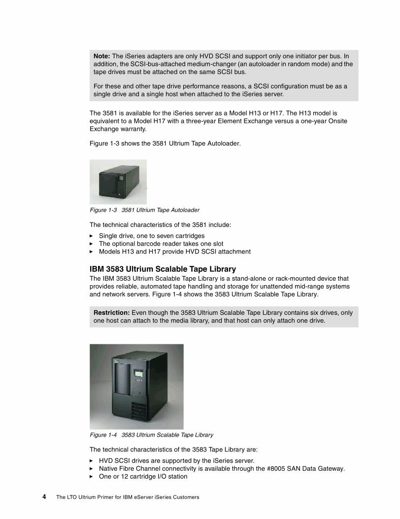
The 3581 is available for the iSeries server as a Model H13 or H17. The H13 model is equivalent to a Model H17 with a three-year Element Exchange versus a one-year Onsite Exchange warranty.
Figure 1-3 shows the 3581 Ultrium Tape Autoloader.
Figure 1-3 3581 Ultrium Tape Autoloader
The technical characteristics of the 3581 include:
� Single drive, one to seven cartridges � The optional barcode reader takes one slot� Models H13 and H17 provide HVD SCSI attachment
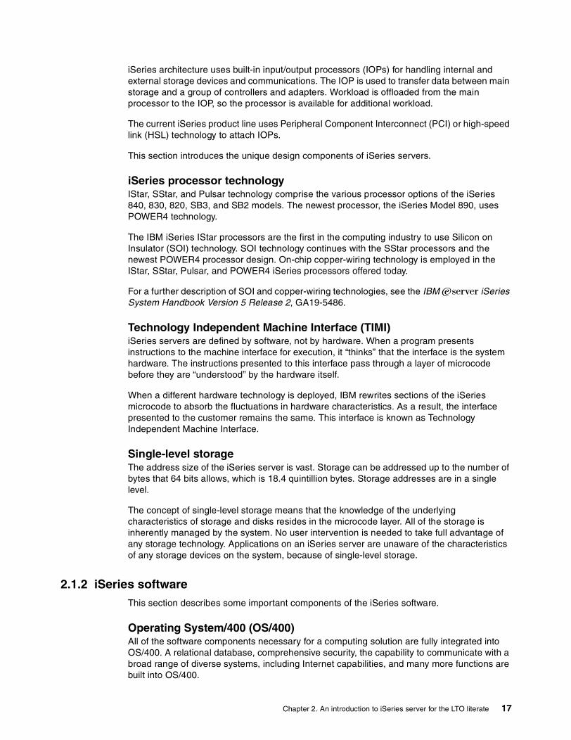
IBM 3583 Ultrium Scalable Tape LibraryThe IBM 3583 Ultrium Scalable Tape Library is a stand-alone or rack-mounted device that provides reliable, automated tape handling and storage for unattended mid-range systems and network servers. Figure 1-4 shows the 3583 Ultrium Scalable Tape Library.
Figure 1-4 3583 Ultrium Scalable Tape Library
The technical characteristics of the 3583 Tape Library are:
� HVD SCSI drives are supported by the iSeries server.� Native Fibre Channel connectivity is available through the #8005 SAN Data Gateway.� One or 12 cartridge I/O station
Note: The iSeries adapters are only HVD SCSI and support only one initiator per bus. In addition, the SCSI-bus-attached medium-changer (an autoloader in random mode) and the tape drives must be attached on the same SCSI bus.
For these and other tape drive performance reasons, a SCSI configuration must be as a single drive and a single host when attached to the iSeries server.
Restriction: Even though the 3583 Ultrium Scalable Tape Library contains six drives, only one host can attach to the media library, and that host can only attach one drive.
4 The LTO Ultrium Primer for IBM eServer iSeries Customers

� Model L18 offers one to six drives and initially supports 18 cartridges.� Model L36 offers one to six drives and initially supports 36 cartridges.� Model L72 offers one to six drives and supports a maximum of 72 cartridges.
IBM 3584 UltraScalable Tape LibraryThe IBM 3584 UltraScalable Tape Library is a stand-alone device that provides reliable, automated tape handling, and storage for unattended mid-range systems and network servers.
Figure 1-5 shows the 3584 Tape Library Model L32 base frame.
Figure 1-5 3584 Tape Library: Model L32
Technical characteristics of the 3584 Tape Library are:
� Modular, scalable design features� Native Fibre Channel or SCSI LTO drives � Multipath architecture with up to 12 logical library partitions per frame� One to six frames: One base frame and up to five expansion frames
3584 Tape Library, Model L32The technical characteristics of the 3584 Tape Library Model L32 include:
� Supports 87 cartridges, up to a maximum of 281 cartridges� Functionally priced 141-cartridge entry capacity� Up to 28.1 TB, 56.2 TB compressed� Standard ten cartridge I/O station� Standard dual picker� SCSI-3 medium changer robotics� Up to 72 logical libraries
3584 Tape Library, Model D32 LTO Expansion UnitThe technical characteristics of the 3584 Tape Library Model D32 include:
� Zero to 12 LTO drives � Supports 396 cartridges, up to a maximum of 440� Up to 44 TB, 88 TB compressed� Supports up to 72 logical libraries
Tip: The 3583 Tape Library can use LVD drives when installed behind a built-in gateway.
Chapter 1. An introduction to LTO for the iSeries literate 5

� Up to 12 logical libraries� Supports up to 2481 tape cartridges
3584 Tape Library, Model D42 DLT Expansion UnitThe technical characteristics of the 3584 Tape Library Model D42 include:
� Zero to 12 DLT 8000 drives� Supports 322 tape cartridges, up to a maximum of 360 cartridges� Up to 14 TB, 28 TB compressed� Up to six logical libraries
Figure 1-6 shows a 3584 UltraScalable Tape Library with six frames.
Figure 1-6 3584 UltraScalable Tape Library
The configuration options of the UltraScalable frames show the great scalability and growth option of the 3584 Tape Library. Figure 1-6 shows a full range six-frame based 3584 UltraScalable Tape Library. It always contains one 3584 Tape Library Model L32 Base frame. Additional 3584-D32 or 3584-D42 frames are added as needed, up to six frames. This configuration applies to iSeries solutions, as well as other platforms.
1.2.2 358x capacitiesTable 1-1 shows a summary of the drive and cartridge capacity for each 358x model supported by the iSeries server. Note that the tape cartridge capacity depends on the number of tape drives installed.
Table 1-1 358x capacities
Note: The D42 frame is not supported directly from an iSeries server. It is a frame supported by other open platforms in which the iSeries server can participate.
Model Number of drives
Number of cartridges
Capacity uncompressed
Capacity with 2:1 compression
3580 Ultrium Tape Drive 1 1 100 GB 200
3581 Ultrium Tape Autoloader 1 7 700 GB 1.4 TB
3583 Ultrium Scalable Tape Library
1 to 6 18 to 72 1.8 to 7.2 TB 3.6 to 14.4
3584 UltraScalable Tape Library 1 to 72 up to 2481 248.1 TB 496.2 TB
6 The LTO Ultrium Primer for IBM eServer iSeries Customers

1.3 Attachment options for the iSeries serverThere are two attachment options to connect LTO tape drives to the iSeries server:
� SCSI
– Small Computer System Interface (SCSI) is the standard attachment for direct attachment.
– SCSI-3 protocol is used to allow cable length of up to 81 feet (25 m).
– VHDCI or HD68 connectors are available.
� Fibre Channel
– Fibre Channel (FC) with its FC arbitrated loop protocol is the most popular attachment in a SAN environment.
– It is offered with the #2765 PCI Fibre Channel Tape Controller.
– FC allows a cable length of up to 1640 feet (500 meters) with 50-micron core fibre.
– Duplex short wave subscriber connectors (SC) are standard on LTO drives.
All LTO drives supported by the iSeries server offer SCSI attachment. The 3583 and 3584 drives offer SCSI and Fibre Channel attachment options.
For more information on SAN and the iSeries server, see Chapter 7, “SAN and the iSeries server” on page 65.
1.3.1 SCSI attachmentAll IBM LTO Ultrium tape models support one of two SCSI attachments:
� Ultra2/Wide SCSI Low Voltage Differential (LVD) interface with a maximum of 80 MB/s� Ultra/Wide SCSI High Voltage Differential (HVD) interface with a maximum of 40 MB/s
The interface required is determined by the SCSI attachment supported by the host server. The iSeries servers support HVD SCSI attachment only. The 3580, 3581, 3583, and 3584 IBM LTO Ultrium drives offer HVD SCSI attachment.
1.3.2 Fibre attachmentThe 3583 and 3584 IBM LTO Ultrium Tape Libraries support Fibre Channel attachment. The 3584 Tape Library offers native FC drives with one FC port per drive. With the 3583 Tape Library, FC support is done through the optional #8005 SAN Data Gateway (SDG). The gateway is the interface between the tape library with internal LVD SCSI drives and the SAN or Fibre Channel servers. Two Fibre Channel ports are available on the gateway. This means two hosts can be directly connected without a switch or hub.
1.3.3 LTO attachment supportThis section describes the operating system level that is needed for the different open system platforms to support LTO drives.
Note: The #2765 PCI Fibre Channel Tape Controller has a duplex LC connector. The #0371 LC-SC Adapter kit is available or an LC-SC cable has to be used.
Tip: For performance reasons, do not connect more than three drives to one FC port.
Chapter 1. An introduction to LTO for the iSeries literate 7

Operating systems that support the LTO tape drives include:
� AIX 4.3.2 or later� OS/400 V4R4 or later� Microsoft Windows NT 4.0 with Service Pack 6� Microsoft Windows 2000, Build 2195 or later� Sun Solaris 2.6, Solaris 7, Solaris 8� HP-UNIX 11.0� Red Hat Linux� Tru64
1.4 Tape consolidationAn important benefit of Storage Area Network (SAN) is storage consolidation. Storage consolidation offers the possibility to attach storage to multiple servers concurrently, and in doing so, leverages the I/T investment.
SAN storage consolidation involves the consolidation of tape storage (what may be called a tape farm). In enterprises with iSeries servers, servers other than iSeries servers, and LTO devices, tape consolidation can be implemented by using LTO tape libraries and switches.
This section introduces tape consolidation using LTO devices with an iSeries server and with non-iSeries servers. You can find further information in The IBM LTO Tape Library Sharing V2 white paper, which is available on the Web at:
http://w3-1.ibm.com/sales/systems/
1.4.1 Sharing an IBM UltraScalable Tape Library using partitioning The 3584 UltraScalable Tape Library has a multipath architecture that allows homogeneous and heterogeneous host servers to share the library’s robotics. The 3584 Tape Library can be partitioned into logical libraries, each host server using its own logical library. Each logical library has its own drives, cartridge storage slots, and control paths. Cartridges under library control are not shared between logical libraries, nor are they allowed to be moved between logical libraries.
1.4.2 Sharing an LTO device using switchesIn OS/400 V5R2, you can use switches in switched fabric mode. This enables you to share one or more IBM Ultrium Scalable Tape Libraries (3583 Tape Library) among heterogeneous host servers, by connecting them via switches. It also enables you to share one or more Fibre Channel-attached drives in a 3584 Tape Library among heterogeneous host servers, by connecting them via switches. For a description of switched fabric and switches, see 7.4, “SAN parts and how they relate to iSeries” on page 68.
Figure 1-7 shows a possible scenario of tape consolidation with the 3583 Tape Library. Two Fibre Channel-attached 3583 Tape Libraries are connected via switches to an iSeries server and another host. Each server is connected via two switches to the two tape libraries.
8 The LTO Ultrium Primer for IBM eServer iSeries Customers

Figure 1-7 Tape consolidation with iSeries, other host, and 3583 Tape Library
This method of connection provides better availability, in that if one switch fails, or one path from a host to a switch fails, the host can still use the other switch. Both host servers see all tape drives in both libraries. The same reserve and release rules apply to this shared tape scenario as those that are described in 3.1, “Save and restore test scenarios” on page 24. The second scenario described in the referenced chapter involves a 3584 Tape Library and two different hosts sharing the same LTO tape drive. In this scenario, one Fibre Channel drive in the 3584 Tape Library is shared between iSeries servers by using a switch.
1.5 Future direction of LTO for the iSeries customerWith improved access time and increased reliability, more and more applications are using tape libraries. Digital video and archiving applications, data mining, and other data-intensive applications represent examples of a growing need for storing data on tape storage. As storage demands grow, so will LTO as a storage solution for iSeries customers.
LTO products will follow the trends in the tape industry by enhancements and new features in tape drives, automated systems, and cartridges. These enhancements and new features will be supported as an iSeries solution.
As far as enhancements in transfer rate and capacity are concerned, we are referring to new generations of LTO Ultrium. New generations of LTO are shown in Figure 1-8 to illustrate the directions in tape drives, tape automation, and cartridges.
3583 3583
Switch Switch
iSeries Other server
Chapter 1. An introduction to LTO for the iSeries literate 9

Figure 1-8 Future generations of LTO
Directions in tape drivesThe drives will increase connectivity with Fibre Channel support. The capacity and performance will also increase with next generations of LTO.
Directions in tape automationSmall and medium automated systems (3581 Ultrium Tape Autoloader and 3583 Ultrium Scalable Tape Library) will increase connectivity by Fibre Channel support. They will also benefit in performance and capacity with the next generations of LTO.
The 3584 UltraScalable Tape Library will increase capacity with additional frames and tape drives. Performance and capacity will continue to improve with the next generations of LTO.
CartridgesFuture generations of LTO will bring cartridges with larger capacity.
1.6 Sample customer implementationsThis section describes the use of LTO tape drives in a typical small, medium, and large iSeries customer environment.
1.6.1 Small customer environment: Single host and LTO Ultrium tape with one drive
This scenario is for a smaller business. The iSeries server has one direct-attached LTO tape. The customer has no need to share the tape. The solution is focused on a low-cost investment.
Four-Generation Roadmap
LTO Ultrium generation 1
200 GB
20-40 MB/sec
LTO Ultrium generation 2
400 GB
40-80 MB/sec
LTO Ultrium generation 3
800 GB
80-160 MB/sec
LTO Ultrium generation 4
1,6 TB
160-320 MB/sec
CompressedcapacityCompressed transfer rate
10 The LTO Ultrium Primer for IBM eServer iSeries Customers

The configuration consists of:
� One iSeries host (server) connected directly to a 3580, 3581, or 3583 Tape Library� SCSI-attached 3580, 3581� 3583 has an additional FC attachment option with the integrated #8005 SAN Data
Gateway
Figure 1-9 shows one iSeries server (host) connected to a 3583 Ultrium Scalable Tape Library.
Figure 1-9 Single iSeries and 3583 Tape Library
1.6.2 Medium customer environment: Single host and LTO Ultrium tape with one or more drives
In this scenario, the customer has two iSeries servers. One server is used for production, and the second server is for testing and backup and recovery. The customer wants to share the LTO tape library between the two iSeries servers. In addition, the implementation involves the ability to save and restore with more than one drive (in parallel) to shorten the save/restore time.
With the FC attachment, a fast attachment with longer distance option is selected. No further SAN components, such as a switch or hub, are needed in this case.
The configuration consists of:
� Two iSeries servers, each FC connected to an 3583 Ultrium Scalable Tape Library
� The attachment is either directly made to the two FC Ports of the 3583 SAN Data Gateway, or a switch or hub can be used in place of the gateway.
� All drives (one to six) can be seen from both iSeries servers.
� Parallel save/restore is supported.
Note: Only one drive and one host are supported if the 3583 Tape Library is SCSI attached to an iSeries server.
SCSI
iSeries Drive 1
3580, 3581 or 3583 LTO
Chapter 1. An introduction to LTO for the iSeries literate 11

Figure 1-10 shows two iSeries servers connected to a 3583 Ultrium Scalable Tape Library.
Figure 1-10 Two iSeries servers and a 3583 Tape Library
1.6.3 Large customer environment: Several iSeries hosts (single host platform) and the 3583 Tape Library
In this large customer environment scenario, the customer has different iSeries servers (or logical partitions in one iSeries server) for different applications, representing different countries. For example, production and data warehouse applications run on a separate iSeries server (or in a separate partition) than the corporation’s Lotus Notes applications. In this scenario, the LTO tape library is to be shared within the iSeries platform only. FC attachment and SAN network is recommended. To adjust performance between iSeries servers and FC ports of the LTO Library, zoning is planned.
This large customer scenario consists of a configuration comprised of more than two iSeries servers. The iSeries solution is SAN connected to a 3583 Ultrium Scalable Tape Library.
The configuration consists of:
� A FC attachment with a zoned hub or switch:
– The production and warehouse iSeries servers use port 1.– The Lotus Notes iSeries server uses port 2.
� All drives (one to six) can be seen by all iSeries servers.
� Parallel save/restore is supported.
Figure 1-11 shows three iSeries servers connected to a 3583 Ultrium Scalable Tape Library.
SDG
iSeries
Drive 4
Drive 2
Drive 3
Drive 1
Drive 5
Drive 6
iSeries
3583 LTO
Note: This solution is restricted to one single-host platform and a maximum of six LTO drives.
12 The LTO Ultrium Primer for IBM eServer iSeries Customers

Figure 1-11 Three iSeries and 3583 Tape Library with a zoned hub or switch
You can find further SAN-related information in Chapter 7, “SAN and the iSeries server” on page 65.
1.6.4 Large customer environment: Multihost platform with logical libraries and 3584 Tape Library
This customer has different iSeries servers or logical partitions in one iSeries server for different applications. For example, production, data warehouse, and Lotus Notes applications run on separate servers (or separate partitions) to support each of the country’s departments. The LTO tape library is to be shared on the iSeries platform with other existing open platforms. Therefore, the logical library function of the 3584 Tape Library is used. In the following example, two drives for each platform are available.
This flexible tape solution incorporates the flexibility and diversity to address future growth. For example, tape drives and server platforms can be added as the business needs to justify the investment.
The requirements include:
� A minimum of one drive per logical library
� Assignment of drives and cartridge slots for each logical library is done through microcode setup.
� FC drives and SCSI drives can be mixed in a 3584 Tape Library.
Figure 1-12 shows multihosts connected to an 3584 UltraScalable Tape Library.
SDG
Drive 4
Drive 2
Drive 3
Drive 1
Drive 5
Drive 6
Hub or Switch
iSeriesServers
A
A
A
BB
Production
Lotus Notes
3583 LTO
A and B Zones
Warehouse
Note: The 3584 Tape Library has different logical libraries for each host platform (iSeries, Windows NT, and pSeries).
Chapter 1. An introduction to LTO for the iSeries literate 13

Figure 1-12 Multihost platform and 3584 with logical libraries
You can find more examples of FC-attached tape implementation in Chapter 7 of the IBM RedDraft IBM ~ iSeries in Storage Area Networks: A Guide to Implementing FC Disk and Tape with iSeries, SG24-6220.
Tip: Assign a control path for each zone or logical library in the 3584 Tape Library to see all drives for iSeries.
DRIVE
1
DRIVE
2
Logical Library 1
Logical Library 2
Logical Library 3
Library Controller
DRIVE
3
DRIVE
4
DRIVE
5
DRIVE
6
to Host 1
to Host 2
to Host 3
iSeries
SCSI LVDup to 12m
Router2108-R03 LVD
FC up to 500 meters
FC up to 500 meters
FC
SCSI LVDup to 12m
Local
Remote
Windows NT
pSeries
3584 LTO
14 The LTO Ultrium Primer for IBM eServer iSeries Customers

Chapter 2. An introduction to iSeries server for the LTO literate
The IBM ~ family is a milestone in a journey that began some years ago to deliver the integration and function required for e-business. With this initiative, IBM responds to the unprecedented demands being made on infrastructures, both in terms of workload and user expectations. The IBM ~ initiative is an integrated approach to building a flexible e-business infrastructure that includes servers, storage, software, and services.
The IBM ~ initiative advantage is an integrated value proposition that delivers:
� New tools for managing e-business� Application flexibility� Innovative technology that delivers leading server performance
The IBM ~ family includes four product lines, which includes:
� iSeries� pSeries� zSeries� xSeries
2
© Copyright IBM Corp. 2002. All rights reserved. 15

2.1 Brief description of the IBM eServer iSeries serveriSeries servers are the first-choice of systems for companies that want the benefits of e-business without the complexity. The iSeries product line offers the most integrated and flexible set of servers in the industry, designed for small and medium businesses, and scalability for large business solutions.
The iSeries servers currently marketed by IBM are:
� Model 890� Model 840� Model 830� Model 820� Model 270� Model SB3� Model SB2
Customers can choose between single and multi-processor models, and gradient processor speeds, for an effective iSeries solution. The AS/400e Model 250 is also marketed as a customized entry-level solution.
The iSeries server product line is shown in Figure 2-1.
Figure 2-1 The iSeries product line
2.1.1 iSeries architectureiSeries servers are designed for business computing. The microprocessor hierarchy design gives the iSeries outstanding performance and a method of integrating diverse environments into a single customer solution. The microprocessors that look after a particular I/O device are accommodated in I/O cards that fit into slots on the system buses.
16 The LTO Ultrium Primer for IBM eServer iSeries Customers
iSeries architecture uses built-in input/output processors (IOPs) for handling internal and external storage devices and communications. The IOP is used to transfer data between main storage and a group of controllers and adapters. Workload is offloaded from the main processor to the IOP, so the processor is available for additional workload.
The current iSeries product line uses Peripheral Component Interconnect (PCI) or high-speed link (HSL) technology to attach IOPs.
This section introduces the unique design components of iSeries servers.
iSeries processor technologyIStar, SStar, and Pulsar technology comprise the various processor options of the iSeries 840, 830, 820, SB3, and SB2 models. The newest processor, the iSeries Model 890, uses POWER4 technology.
The IBM iSeries IStar processors are the first in the computing industry to use Silicon on Insulator (SOI) technology. SOI technology continues with the SStar processors and the newest POWER4 processor design. On-chip copper-wiring technology is employed in the IStar, SStar, Pulsar, and POWER4 iSeries processors offered today.
For a further description of SOI and copper-wiring technologies, see the IBM ~ iSeries System Handbook Version 5 Release 2, GA19-5486.
Technology Independent Machine Interface (TIMI)iSeries servers are defined by software, not by hardware. When a program presents instructions to the machine interface for execution, it “thinks” that the interface is the system hardware. The instructions presented to this interface pass through a layer of microcode before they are “understood” by the hardware itself.
When a different hardware technology is deployed, IBM rewrites sections of the iSeries microcode to absorb the fluctuations in hardware characteristics. As a result, the interface presented to the customer remains the same. This interface is known as Technology Independent Machine Interface.
Single-level storage The address size of the iSeries server is vast. Storage can be addressed up to the number of bytes that 64 bits allows, which is 18.4 quintillion bytes. Storage addresses are in a single level.
The concept of single-level storage means that the knowledge of the underlying characteristics of storage and disks resides in the microcode layer. All of the storage is inherently managed by the system. No user intervention is needed to take full advantage of any storage technology. Applications on an iSeries server are unaware of the characteristics of any storage devices on the system, because of single-level storage.
2.1.2 iSeries softwareThis section describes some important components of the iSeries software.
Operating System/400 (OS/400)All of the software components necessary for a computing solution are fully integrated into OS/400. A relational database, comprehensive security, the capability to communicate with a broad range of diverse systems, including Internet capabilities, and many more functions are built into OS/400.
Chapter 2. An introduction to iSeries server for the LTO literate 17

To achieve the functionality that is standard in OS/400, a customer on a customary machine would need to integrate typically between 10 and 25 different modules of software. OS/400 is installed with all of these capabilities as standard. OS/400 customers do not have to install individual system software components.
JavaJava is a key application development environment for iSeries customers. The AS/400 Developer Kit for Java development tool supports Sun’s Java 2. The Java virtual machine, which resides beneath the Technology Independent Machine Interface, enables fast interpretation and execution of Java code on the iSeries servers.
Web servingOS/400 contains a complete set of base products and features that can be used to create a Web presence. Included are TCP/IP, Java, Virtual Private Networking, cryptographic services, Secure Socket Layer, HTTP Server, Apache Server for iSeries, and many more. The WebSphere family of products offered by IBM for iSeries allows a customer to build a complete e-business Web site that is secure, easy to develop and maintain, and scale, based on the customer’s needs.
Lotus DominoDomino for iSeries is the leading groupware solution available for the iSeries server. It provides capability for iSeries customers to use their business data in collaborative e-business solutions, both within their organizations and with their partners over the Internet.
2.1.3 Other important features of OS/400 and iSeries serversThis section describes other iSeries strengths that bring benefit to a customer.
DatabaseDB2 Universal Database (UDB) for iSeries offers state of the art database functions while providing the stability and ease of use that have become the trademark of the iSeries server. DB2 UDB for iSeries is fully integrated into the OS/400 operating system. It is not a separate product. This fact allows the operating system to control some of its management functions. It also makes it easy to maintain, reducing the need for a dedicated database administrator. DB2 UDB for iSeries fully exploits the 64-bit iSeries hardware.
Logical partitioning (LPAR)Logical partitioning enables a customer to run multiple independent OS/400 instances or partitions, each with its own processors, memory, and disks in an iSeries server. This way a customer can address multiple system requirements in a single machine to achieve server consolidation, business unit consolidation, mixed production/test environments, and integrated clusters.
Linux for iSeriesiSeries supports Linux running in a logical partition. Up to 31 Linux partitions are supported depending on the iSeries model. With Linux for iSeries, a customer can use a new stream of e-business applications to complement the strengths of the iSeries as an integrated core business solution. Linux running in an iSeries partition inherits important strengths and reliability features of the iSeries architecture.
18 The LTO Ultrium Primer for IBM eServer iSeries Customers

High-speed linksBesides Peripheral Component Interconnect (PCI) technology for buses, iSeries also uses a new bus structure using HSLs. HSL loop technology provides high-speed data transportation. It is used for connecting:
� The iSeries server to expansion towers that contain storage devices� Two or more iSeries servers in a cluster� Towers with switchable data between iSeries servers in a cluster
2.2 iSeries servers The iSeries server is designed to deliver the compute-intensive performance required by Java, WebSphere, Linux, Domino, and other emerging workload applications and environments. This section briefly describes the more popular iSeries models and their capabilities.
iSeries 890 serverThe customer has a a choice of different models, ranging from a 16-processor model to 32-processor models.
The characteristics of the capacity of the iSeries 890 server include:
� Main storage can be as large as 265 GB.� Disk storage can be as large as 71 TB.� Up to 480 communication lines are provided. � Up to 128 LAN ports are provided.� Capability to attach external storage devices (disk and tape units) in a SAN through Fibre
Channel
iSeries 840 serverWith the iSeries 840 server, the customer has a choice of different models, ranging from 8-processor models to 24-processor models.
Following are the characteristics of the capacity of the iSeries 840 server:
� Main storage can be as large as 128 GB.� Disk storage can be as large as 37 TB. � Up to 400 communication lines are provided. � Up to 96 LAN ports are provided.� Capability to attach external storage devices (disk and tape units) in a SAN through Fibre
Channel.
iSeries 830 serverWith the iSeries 830 server, the customer has a choice of different models, ranging from a two-processor model to eight-processor models.
The characteristics of the capacity of the iSeries 830 server include:
� Main storage can be as large as 64 GB.� Disk storage can be as large as 22 TB.� Up to 300 communication lines are provided.� Up to 72 LAN ports are provided.� Capability to attach external storage devices (disk and tape units) in a SAN through Fibre
Channel.
Chapter 2. An introduction to iSeries server for the LTO literate 19
iSeries 820 serverWith the iSeries 820 server, the customer has a choice of different models, ranging from one-processor models to four-processor models.
The characteristics of the capacity of the iSeries 820 server include:
� Main storage can be as large as 32 GB.� Disk storage can be as large as 8 TB. � Up to 160 communication lines are provided.� Up to 30 LAN ports are provided.� Capability to attach external storage devices (disk and tape units) in a SAN through Fibre
Channel.
iSeries 270 serverWith the iSeries 270 server, the customer has a choice of single-processor and two-processor models.
The characteristics of the capacity of the iSeries 270 server include:
� Main storage can be as large as 16 GB.� Disk storage can be as large as 844 GB. � Up to 50 communication lines are provided. � Up to 8 LAN ports are provided.� Capability to attach external storage devices (disk and tape units) in a SAN through Fibre
Channel.
2.3 Sample implementation scenariosThis section lists three industrial environments in which the iSeries is typically installed. It also describes the iSeries benefits that make it so valuable in these environments.
Retail distributionRetail distribution enterprises choose iSeries as the server for their core applications mainly because of the following iSeries benefits:
� Reliability� Scalability� Performance� A wide choice of applications� Server consolidation
ReliabilityThe iSeries has an average of only about five hours of unplanned downtime a year. Moreover, it provides possibility for clustering that can reduce downtime to zero.
ScalabilityWith the iSeries server, a customer has a wide range of choices from entry models suitable for smaller enterprises to strong models that can be used in large complex enterprises. All of them run the same operating system OS/400. When a customer’s enterprise grows and upgrades the iSeries to a stronger model, there is no need to redesign or rewrite applications. The same applications can run on all iSeries servers.
PerformanceBecause of the unique iSeries database architecture, Universal Database for iSeries offers superior performance. Also, the new technologies that are employed in iSeries, with every
20 The LTO Ultrium Primer for IBM eServer iSeries Customers

new iSeries server, enable high performance. This enables customers to have on-time, accurate information about their business.
A wide choice of applicationsThe iSeries offers a stable and high-performing platform for SAP, Lotus Domino, Business Intelligence software, e-commerce, and others.
Server consolidationThe iSeries server’s ability to have multiple logical partitions, together with its reliability and scalability, is a good basis for consolidating workload from several servers to iSeries.
ManufacturingManufacturing is another typical industry where the iSeries is employed. Besides server consolidation and rapid implementation of applications, the following iSeries benefits are what make customers in this industry decide on the iSeries server:
� Enhanced reporting capabilities� Enhanced customer service
Enhanced reporting capabilitiesiSeries integrated architecture and good performance enable a manufacturing customer to provide timely and accurate information to their executives and to their customers.
Enhanced customer serviceThe iSeries is a reliable and secure platform for Internet such applications as e-commerce. It also provides a variety of application development tools for Internet applications. With employing Web applications on the iSeries server, an enterprise can improve its customer services.
Banking, finance, and securityBesides reliability and performance, the following factors are what make a typical customer in this industry decide on the iSeries server:
� Investment protection� Security� A technology leader� Rapid implementation of applications
Investment protectionThe iSeries server can run the same operating system and applications on every model, which protects the customer’s investment in IT equipment. When they upgrade to a stronger iSeries model, they do not need to invest in another operating system or other applications.
SecurityWhen working with iSeries Internet applications, users can be confident that their data will be secure. That is because of the many security features that are available on iSeries, such as passwords, encryption keys, and digital identification certificates.
A technology leaderiSeries development keeps employing technology innovations with new iSeries models. This way, iSeries customers experience increased price/performance with every new model, which enables them to maintain a sharp competitive edge.
Rapid implementation of applicationsDue to the iSeries integrated architecture, applications can be implemented in a short time, compared to implementation time on other server platforms.
Chapter 2. An introduction to iSeries server for the LTO literate 21

22 The LTO Ultrium Primer for IBM eServer iSeries Customers

Chapter 3. iSeries external tape storage and save and restore case scenarios
An important component of a tape storage offering is how the solution affects the amount of time to save and restore. This chapter discusses the test cases that were setup to support writing this Redpaper. It also briefly describes the tape devices used in the save and restore testing. The FlashCopy function offered with the Enterprise Storage Server is introduced as an option to reduce the save window.
3
© Copyright IBM Corp. 2002. All rights reserved. 23

3.1 Save and restore test scenariosThe save and restore rates listed in this document are a measurement of running commands in batch jobs. The data selected to save and restore is a library with a mix of object types, including:
� Class� Commands� Data area � Files: File size of 2 MB, 5 MB, 20 MB, 80 MB, 130 MB, and 200 MB � Job description � Programs, commands, and panel groups
A 3580, 3583, 3584, and 3590 Model E11 were set up in a lab environment to support the writing of this Redpaper. Two scenarios were setup for save and restore operations measured on these models. One scenario measures OS/400 native commands to save and restore the NUMX12GB library. The second scenario measures Backup Recovery Media Services/400 (BRMS/400) with control groups. A control group is used to support the use of parallel backup capabilities.
Figure 3-1 shows the measurement in minutes to complete save and restore operations on the 3580, 3583, 3584, and 3590 Model E11 tape devices. The iSeries server was not in restricted state for this test.
Note: NUMX12GB is the name used to describe a mix of data contained in a single library made up of a combination of source files, database files, program and command objects, data areas, menus, query definitions, and other common iSeries objects found in libraries. NUMX12GB contains 52,900 objects.
NUMX12GB is the same workload as what is used to produce the save/restore performance ratings as represented in Chapter 15, “Save/Restore Performance” of the iSeries Performance Capabilities Reference Version 5, Release 2, SC41-0607-05.
24 The LTO Ultrium Primer for IBM eServer iSeries Customers

Figure 3-1 Save and restore tests
3.1.1 3570, 3575, and 3590 external tape devicesThis section describes the 3570, 3575, and 3590 external tape devices supported by the iSeries server. It provides a comparison of features to help position each drive.
To determine the best external tape storage solution for a particular customer, you must understand the customer’s business application and environment, and relate these needs to the characteristics of the external tape storage solution. The factors are numerous and unique to each customer. However, in general, the 3570, 3575, and 3590 external tape device characteristics tend towards a business solution to address these needs:
� 3590
– Mission-critical data protection– Enterprise cross-platform attachment– A high read-and-write duty cycle– Proven Magstar performance and reliability
Note: Backup Recovery Media System/400 (BRMS/400) is a storage management application designed to handle a wide range of tasks for the iSeries customer. BRMS lets you plan, control, and automate your backup, recovery, media, and storage management procedures. This works for both a single iSeries machine and multiple iSeries servers linked in a computing network. You can use BRMS to define policies for such tasks as backup, recovery, archive, and retrieval.
Save Restore0
10
20
30
40
50
Min
utes
3580358335843590 E11
NUMX12GB
Note: Although the 3575 Tape Library Dataserver is withdrawn from marketing effective 28 June 2002, it is included in this Redpaper because it represents a popular offering for iSeries customers.
Chapter 3. iSeries external tape storage and save and restore case scenarios 25

� 358x
– High capacity– Open systems architecture attachment– Write-intensive applications– Enhanced open system reliability
� 3570
– Fast access to data– Read-and-write-intensive applications– Enterprise Magstar reliability– Mission-critical data protection
Figure 3-2 3570, 3580, and 3590 Tape Evolution
The technical specifications of the external tape device also influence the installation decision. Table 3-1 shows the rated technical specifications of the 3570, 3580, and 3590 tape drives, as measured in the lab setup in preparation of this Redpaper.
3590
358X
3570
Magstar 3570
Ultrium
Magstar 3590
3590
IBM Ultrium
3570
26 The LTO Ultrium Primer for IBM eServer iSeries Customers
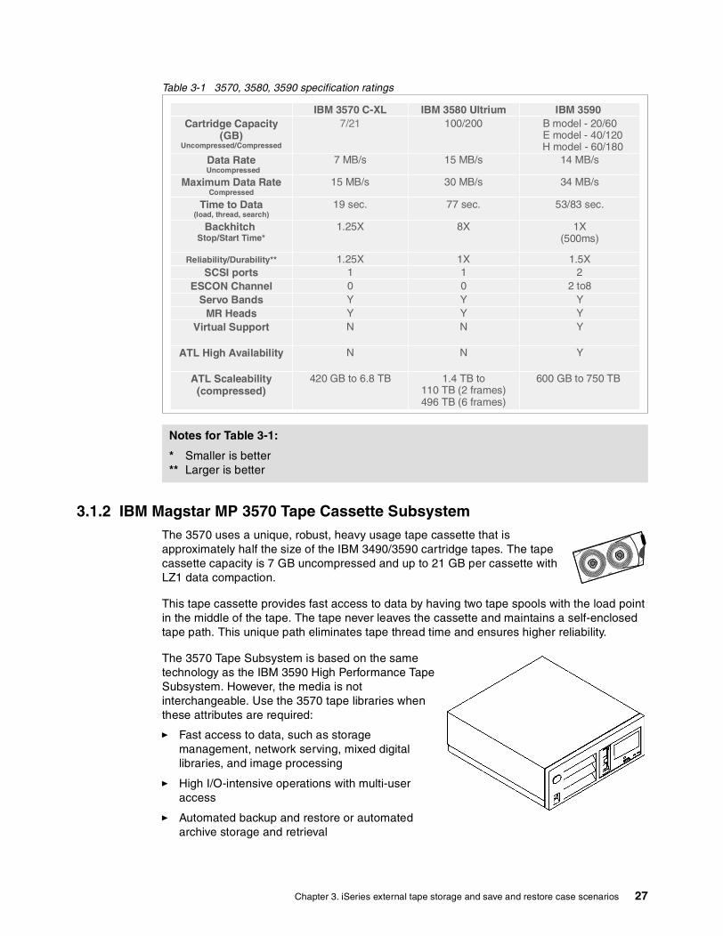
Table 3-1 3570, 3580, 3590 specification ratings
3.1.2 IBM Magstar MP 3570 Tape Cassette SubsystemThe 3570 uses a unique, robust, heavy usage tape cassette that is approximately half the size of the IBM 3490/3590 cartridge tapes. The tape cassette capacity is 7 GB uncompressed and up to 21 GB per cassette with LZ1 data compaction.
This tape cassette provides fast access to data by having two tape spools with the load point in the middle of the tape. The tape never leaves the cassette and maintains a self-enclosed tape path. This unique path eliminates tape thread time and ensures higher reliability.
The 3570 Tape Subsystem is based on the same technology as the IBM 3590 High Performance Tape Subsystem. However, the media is not interchangeable. Use the 3570 tape libraries when these attributes are required:
� Fast access to data, such as storage management, network serving, mixed digital libraries, and image processing
� High I/O-intensive operations with multi-user access
� Automated backup and restore or automated archive storage and retrieval
Notes for Table 3-1:
* Smaller is better** Larger is better
IBM 3570 C-XL IBM 3580 Ultrium IBM 3590 Cartridge Capacity
(GB) Uncompressed/Compressed
7/21 100/200 B model - 20/60 E model - 40/120
H model - 60/180 Data Rate
Uncompressed7 MB/s 15 MB/s 14 MB/s
Maximum Data Rate Compressed
15 MB/s 30 MB/s 34 MB/s
Time to Data(load, thread, search)
19 sec. 77 sec. 53/83 sec.
Backhitch Stop/Start Time*
1.25X 8X 1X(500ms)
Reliability/Durability** 1.25X 1X 1.5XSCSI ports 1 1 2
ESCON Channel 0 0 2 to8Servo Bands Y Y Y
MR Heads Y Y YVirtual Support N N Y
ATL High Availability N N Y
ATL Scaleability(compressed)
420 GB to 6.8 TB 1.4 TB to110 TB (2 frames)496 TB (6 frames)
600 GB to 750 TB
Chapter 3. iSeries external tape storage and save and restore case scenarios 27

The features of the 3570 include:
� Faster data access than other tape technologies with a drive time to read/write data of eight seconds from cassette insertion
� High-speed search function
� Security key lock, which physically locks the cassettes in the library
� Supports random and auto modes
The 3570 C02 and C12 support two drives. It can function in base-mode and split-mode configurations, as illustrated in Figure 3-3.
Figure 3-3 3570 base and split mode
The minimum OS/400 release required to support the 3570 is V3R1. V4R5 is the minimum release when attached via a #2749 PCI Ultra Magnetic Media Controller.
3.1.3 Magstar MP (Multipurpose) 3575 Tape Library DataserverThe IBM Magstar MP 3575 Tape Library Dataserver is a family of automated tape storage solutions. The 3575 is designed for the growing unattended storage requirements of today's midrange systems and network servers. The 3575 is a compact, integrated tape storage library that can expand the capability of tape processing by optimizing both read- and write-intensive operations. A dual-gripper picker can provide fast cartridge exchange times between the library slots and the Magstar MP tape drives in the library.
Figure 3-4 shows the models of the 3575 tape library.
iSeries
TapMLB01Tape1
SCSI
Tape01 Tape02
3570-Cx2TapMLB01
Tape1Tape2
SCSI
Base mode: Two drives attached
Tape01 Tape02
3570-Cx2TapMLB01Tape1
TapMLB02Tape2
SCSI
Split mode: Two drives attached
SCSI
Tape01 Tape02
3570-Cx2TapMLB01
Tape1
SCSI
Split mode: Two drives, two systems attached
x x
x x
iSeries
iSeries iSeries
x
28 The LTO Ultrium Primer for IBM eServer iSeries Customers

Figure 3-4 3575 tape family
Table 3-2 shows the characteristics of the 3575 model.
Table 3-2 3575 characteristics
Summary: Positioning the 358x versus 3570 � The 3570 Magstar MP has no existing roadmap for future generations.
� The LTO family is the follow-on product for 3575 Magstar MP library models.
� While the data access from 3570 is fast, the capacity of the 3570 media cartridge can be a driving cause to change to another storage solution.
� The 358x tape platform is positioned for future data growth.
� Because of the open standard of LTO and good customer acceptance, LTO is easier to exchange media cartridges with other devices.
Model Description Number of drives
Cassette slots
Capacity uncompressed
Capacity with 3:1 compression
L06L12L18L24L32
Stand-alone Tape LibraryMidrange Tape LibraryMidrange Tape LibraryHigh capacity Tape Library
1-21-41-612
60120180240
420 GB840 GB1.26 TB1.68 TB2.26 TB
1.2 TB2.52 TB3.78 TB5.04 TB6.28 TB
Chapter 3. iSeries external tape storage and save and restore case scenarios 29
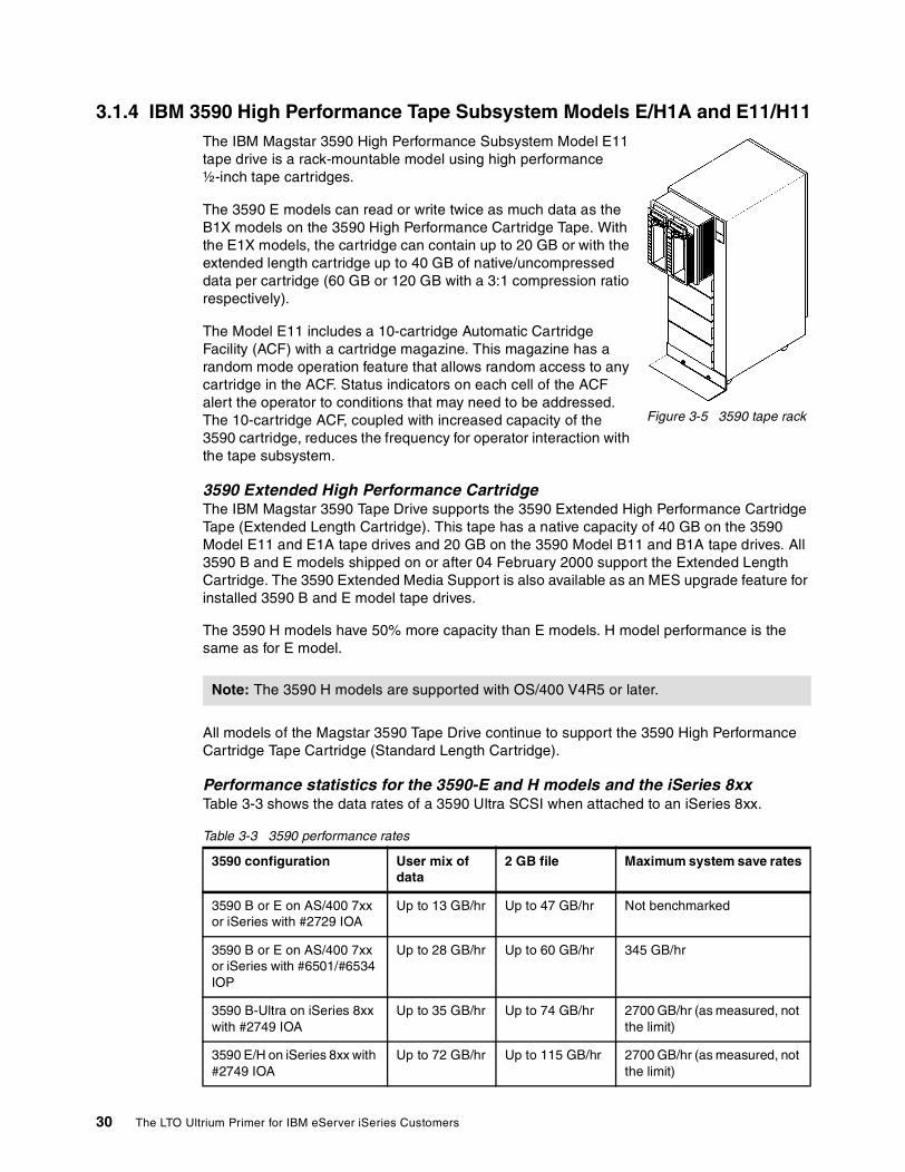
3.1.4 IBM 3590 High Performance Tape Subsystem Models E/H1A and E11/H11The IBM Magstar 3590 High Performance Subsystem Model E11 tape drive is a rack-mountable model using high performance ½-inch tape cartridges.
The 3590 E models can read or write twice as much data as the B1X models on the 3590 High Performance Cartridge Tape. With the E1X models, the cartridge can contain up to 20 GB or with the extended length cartridge up to 40 GB of native/uncompressed data per cartridge (60 GB or 120 GB with a 3:1 compression ratio respectively).
The Model E11 includes a 10-cartridge Automatic Cartridge Facility (ACF) with a cartridge magazine. This magazine has a random mode operation feature that allows random access to any cartridge in the ACF. Status indicators on each cell of the ACF alert the operator to conditions that may need to be addressed. The 10-cartridge ACF, coupled with increased capacity of the 3590 cartridge, reduces the frequency for operator interaction with the tape subsystem.
3590 Extended High Performance CartridgeThe IBM Magstar 3590 Tape Drive supports the 3590 Extended High Performance Cartridge Tape (Extended Length Cartridge). This tape has a native capacity of 40 GB on the 3590 Model E11 and E1A tape drives and 20 GB on the 3590 Model B11 and B1A tape drives. All 3590 B and E models shipped on or after 04 February 2000 support the Extended Length Cartridge. The 3590 Extended Media Support is also available as an MES upgrade feature for installed 3590 B and E model tape drives.
The 3590 H models have 50% more capacity than E models. H model performance is the same as for E model.
All models of the Magstar 3590 Tape Drive continue to support the 3590 High Performance Cartridge Tape Cartridge (Standard Length Cartridge).
Performance statistics for the 3590-E and H models and the iSeries 8xxTable 3-3 shows the data rates of a 3590 Ultra SCSI when attached to an iSeries 8xx.
Table 3-3 3590 performance rates
Note: The 3590 H models are supported with OS/400 V4R5 or later.
3590 configuration User mix of data
2 GB file Maximum system save rates
3590 B or E on AS/400 7xx or iSeries with #2729 IOA
Up to 13 GB/hr Up to 47 GB/hr Not benchmarked
3590 B or E on AS/400 7xx or iSeries with #6501/#6534 IOP
Up to 28 GB/hr Up to 60 GB/hr 345 GB/hr
3590 B-Ultra on iSeries 8xx with #2749 IOA
Up to 35 GB/hr Up to 74 GB/hr 2700 GB/hr (as measured, not the limit)
3590 E/H on iSeries 8xx with #2749 IOA
Up to 72 GB/hr Up to 115 GB/hr 2700 GB/hr (as measured, not the limit)
Figure 3-5 3590 tape rack
30 The LTO Ultrium Primer for IBM eServer iSeries Customers

These data rates are unleashed, and the performance of tape operations is twice as high than is possible on AS/400e 6xx and 7xx models. In addition, the system maximum throughput (concurrent tape device operations) is increased by up to 700% (as measured, not the limit). Also, there are no longer any limitations on the bus placement concerning the number of tape devices or the configurations with DASD.
IBM 3494 Tape Library Dataserver modelThe 3494 Tape Library Dataserver is a stand-alone automated tape storage subsystem for ½-inch cartridges available for attachment to the iSeries server. It provides an automated tape solution for automating tape operations such as save and restore, migration of data between disk and tape, and other mass data applications.
Summary: 358x versus 3590 � The 3590 Magstar has an existing roadmap for future generations.
� For performance reasons, the 3590 Magstar is a real alternative to IBM LTO especially if intensive Read and Write Operations are required, because the 3590 positions faster to single objects on tape.
� In streaming mode, the 3590 Magstar and IBM LTO show similar performance.
� The installation requirements and the investment costs for the same capacity are higher for the 3590 Magstar than with IBM LTO.
� 3590 tape drives and 3494 tape libraries are typically found for zSeries customers because LTO is not supported in this environment.
� The IBM LTO is the preferred platform for open-system environments to share the tape drives with other platforms.
3590 E/H on iSeries 8xx with #2765 IOA
Up to 78 Gb/hr Up to 120 GB/hr(4 GB files)
2700 GB/hr (not measured)
Note: Tape drive data rates represent a 2.4:1 compressible data ratio. The performance data contained here was obtained in a controlled environment, based on the use of specific data. Actual results that may be obtained in other operating environments may vary significantly. These values do not constitute a guarantee of performance.
Note: All information being released represents the current intent of IBM, is subject to change, and represents goals or objectives only.
3590 configuration User mix of data
2 GB file Maximum system save rates
Chapter 3. iSeries external tape storage and save and restore case scenarios 31

3.2 Using ESS FlashCopy to reduce the time to saveAs the amount of data being stored increases, so does the amount of time it takes to back up that data using a particular backup solution. The amount of time available to carry out the backup is known as the backup window or the save window. Typically, the backup window is a finite period of time during the evening hours when the computing system has fewer, or no, users online.
If the customer approaches a point when there is not enough time to complete the backup in the current backup window, it is necessary to look for a different backup solution.
The backup solution with FlashCopy function available with the IBM Enterprise Storage Servers (ESS) can reduce the save window to zero. This section briefly describes this capability.
Using ESS as external disk storage for iSeries opens up these possibilities:
� The ability to place all iSeries disk space on ESS. Since the load source is internal to the iSeries server, it is mirrored to the ESS.
� The flexibility to use a portion of the ESS as storage for the iSeries server. This assignment is done by implementing independent auxiliary storage pools (IASPs).
ESS FlashCopy takes a point-in-time copy of the data within ESS. FlashCopy works on ESS logical units (volumes), so it makes a copy of all the data that reside on one or more volumes.
To implement a backup solution for the iSeries with ESS FlashCopy, two iSeries servers, or two LPARs connected to the same ESS are required.
To illustrate this concept, consider two iSeries servers – iSeries1 and iSeries2. All of the disk space of iSeries1 is on an ESS. FlashCopy is used to copy all iSeries1 data within the ESS disk space. iSeries2 is connected to the ESS volumes that are a copy of iSeries1’s disk space. A backup is taken from this copy. In this way, the backups for iSeries1 are taken by iSeries2. Therefore, iSeries1 does not require a backup. The backup window is zero.
For a detailed description of the ESS FlashCopy function and how to use it for backup, refer to the RedDraft IBM ~ iSeries in Storage Area Networks: A Guide to Implementing FC Disk and Tape with iSeries, SG24-6220. To understand Independent ASPs, refer to the Redbook Clustering and IASPs for Higher Availability on the IBM ~ iSeries Server, SG24-5194.
32 The LTO Ultrium Primer for IBM eServer iSeries Customers

Chapter 4. Planning for Ultrium external tape devices
As with any computing system, planning is necessary to prepare for the installation of storage devices. This chapter discusses the ordering and installation factors required for a successful iSeries and Ultrium Tape implementation.
4
© Copyright IBM Corp. 2002. All rights reserved. 33

4.1 Description of physical planning requirementsPlanning for the physical installation of the LTO tape devices involves floor space requirements, power cord specifications and length, power plug and power receptacle options and specifications. The power, space, and cabling requirements differ by the model of Ultrium Tape device installed.
The following manuals can help to prepare for the physical installation of the LTO tape drives:
� IBM 3580 Ultrium Tape Drive Setup, Operator, and Service Guide, GA32-0415� IBM 3581 Ultrium Tape Autoloader Setup, Operator, and Service Guide, GA32-0412� IBM 3583 Ultrium Scalable Tape Library Setup and Operator Guide, GA32-0411� IBM 3584 UltraScalable Tape Library Planning and Operator Guide, GA32-0408
You can find further planning information in:
� Informational APAR II12621 � The white paper IBM LTO Tape Library Sharing V2: This paper is located in the LTO Sales
Kit on the Web at: http://w3-1.ibm.com/sales/systems/ibmsm.nsf/mainframeset?openform&geo=AM
4.2 iSeries prerequisites for the IBM LTOThis section explains the hardware and software prerequisites to support IBM LTO tape and library models on the iSeries server.
4.2.1 Hardware prerequisitesThe hardware required to support LTO drives on iSeries servers depends on the attachment method required.
SCSI-attached external tapeA SCSI tape adapter (IOP) on iSeries server is needed for attaching SCSI LTO Tape and Library. Depending on the installed iSeries hardware model, select one of these adapters:
� #2729 PCI Magnetic Media Controller� #2749 PCI Ultra Magnetic Media Controller� #6501 Tape/Disk Device Controller� #6534 Magnetic Media Controller
The transfer rate varies for each SCSI tape adapter. The transfer ratings for each of the supported iSeries tape adapters are shown in Table 4-1.
Table 4-1 iSeries tape adapters
IOP or IOA Transfer rate/user mix of data
#2729 PCI Magnetic Media Controllerr HVD, HD68
Up to 13 MB/s (47 GB/hr)
#6501 Magnetic Media Subsystem Controller IOP (SPD)HVD
Up to 17 MB/s (60 GB/hr)
#6534 Magnetic Media Controller (SPD)HVD, HD68
Up to 17 MB/s (60 GB/hr)
34 The LTO Ultrium Primer for IBM eServer iSeries Customers

To maximize the performance required for the application, implement an appropriately rated adapter and plan accordingly.
FC-attached external tapesThe #2765 PCI Fibre Channel Tape Controller is required when attaching external FC tape. The 3583 has two FC ports on the #8005 Integrated SAN Data Gateway feature. The 3584 has one FC port on each FC drive.
These iSeries server models support the #2765 PCI Fibre Channel Tape Controller:
� 270� 820� 830� 840� 890� SB2� SB3
The LTO side of the FC connection is made directly to the iSeries or with a switch or hub through the FC port.
Refer to Chapter 7, “SAN and the iSeries server” on page 65, for further planning considerations for a SAN environment, including information on hubs and switches.
4.2.2 Software prerequisitesThe minimum operating system level required to support IBM LTO Tape/Libraries is shown in Table 4-2.
Table 4-2 Minimum OS/400 to support LTO
For further software requirements, refer to Information APAR II12621 in the APAR Search page of the Software Knowledge database at:
http://www-1.ibm.com/support/apar_search.html
#2749 PCI Ultra Magnetic Media ControllerHVD, HD68OS/400 V4R5 or later
Up to 38 MB/s (137 GB/hr)
#2765 PCI Fibre Channel Tape Controller(3583/3584 fibre attached features only)
Up to 100 MB/s
Important: Only the HVD drives from LTO Tape Libraries are supported on iSeries servers. However, the #8005 SAN Data Gateway (SDG) supports LVD drives internal to the 3583 Tape Library.
Note: D-IPL directly from FC tapes is not supported. See Chapter 5, “Perform an IPL from an Alternative Device” in Backup and Recovery, SC41-5304, for more information
IOP or IOA Transfer rate/user mix of data
Attachment type Minimum OS/400
SCSI V4R4
Fibre channel V5R1
Chapter 4. Planning for Ultrium external tape devices 35

4.3 Performance considerationsMany factors influence the observable performance differences of save and restore operations. These factors include:
� The hardware capabilities (that is, the capability of the tape drive)� The tape input/output processor (IOP) to which the device attaches� Placement of the tape IOP in the system (on the bus) � Type of workload saved or restored (the size of the file and mix of the data records)
Using data compression, data compaction, and the Use Optimum Block Size (USEOPTBLK) parameter on OS/400 commands also influence the performance of save and restore operations.
When planning for performance, consider the following parameters, which influence the “real” transfer rate of tape performance:
� iSeries server model: The processor speed of the iSeries product line range from 400 MHz to 1.3 GHz
� Adapter cards (see Table 4-1)� Native transfer rate of the LTO drive � Compression factor� Block value specified on the save and restore commands� File size � Server load and disk transfer rate� Network bandwidth
You can find additional information about performance in:
� iSeries Performance Capabilities Reference Version 5, Release 1, SC41-0607-04� iSeries Performance Capabilities Reference Version 5, Release 2, SC41-0607-05
Refer to Chapter 15 in each of these Performance Capabilities publications to find a summary of the save and restore tests performed by IBM.
4.4 Related servicesIBM Global Service Organization provides fee service support for:
� Implementing IBM tape libraries� Implementing software solutions (Backup Recover Media Services/400 and IBM Tivoli
Storage Manager)
Contact your regional IBM service organization for further information.
36 The LTO Ultrium Primer for IBM eServer iSeries Customers

Chapter 5. LTO media
Tape provides efficient data protection to recover lost data and for archive applications. The growth of storage needs for such applications as e-business requires capacity, performance, reliability, and automation. To meet these requirements, a specifications roadmap for two tapes formats was produced in 1998. With dimensions of 21.5 mm x 102 mm x 105.4 mm (or 0.8 inches x 4 inches x 4.1 inches), the cartridge is smaller than other single reel tape cartridges.
At the end of 2000, Ultrium tape drives became available on market. You can find information about Linear Tape-Open (LTO) on the Web site at:
http://www.lto-technology.com
This chapter introduces the Ultrium format and its characteristics. Ultrium tape drives were announced for the iSeries in late 2000. This chapter discusses tape media in general and introduces the media used by the Ultrium drives.
For considerations regarding media when migrating from other tape devices to the Ultrium tapes, see 5.2.1, “Migrating to the LTO from other iSeries tape drives” on page 40.
5
© Copyright IBM Corp. 2002. All rights reserved. 37

5.1 Media considerations and requirementsLTO development is dedicated to the Ultrium format. The LTO tape format is a reliable, open format solution. It meets the important characteristics for an effective backup and restore process, such as:
� Reliability � Performance � Scalability
5.1.1 Benefits of using the Ultrium formatThe high capacity Ultrium format allows for 100 GB capacity (200 GB with 2.1 compression) in a single compact cartridge. The cartridge is smaller than other single reel tape cartridges.
5.1.2 High data transfer rateThe media format for Ultrium technology is designed with a four-generation roadmap that provides up to 1.6 TB of data per cartridge. The fourth generation of the Ultrium format provides a compressed transfer rate up to 320 MB/s. Table 5-1 shows this Ultrium format roadmap.
Table 5-1 Utrium format roadmap
5.1.3 Wide range of applications The Ultrium tape format is an efficient tape for the high capacity backup and archive operations. Using data compression improves the process of backup and is helpful when using a wide variety of applications. The Ultrium tape format is ideally suited for:
� Open system server solutions� Large archive capacity� High streaming performance� Backup and restore applications� Enhanced open-system reliability� Tape automation
5.1.4 Cartridge memoryThe Ultrium tape cartridges support the Linear Tape-Open Cartridge Memory (LTO CM) through the use of LTO CM (cartridge memory). LTO CM is an embedded electronics and interface module that can store and retrieve a cartridge's historical usage and other information. The LTO CM is read during the load and unload operations. This improves data access speeds by avoiding read/write of the cartridge data after the load or before it is unloaded.
LTO UltriumGeneration 1
LTO UltriumGeneration 2
LTO UltriumGeneration 3
LTO UltriumGeneration 4
Native capacity 100 GB 200 GB 400 GB 800 GB
Compressed capacity
200 GB 400 GB 800 GB 1.6 TB
Transfer rate (native) 10 to 20 MB/s 20 to 40 MB/s 40 to 80 MB/s 80 to 160 MB/s
Compressed transfer rate (native)
20 to 40 MB/s 40 to 80 MB/s 80 to 160 MB/s 160 to 320 MB/s
38 The LTO Ultrium Primer for IBM eServer iSeries Customers

5.1.5 ReliabilityAfter the data is written to tape, it is immediately read to check that it is written correctly. If incorrect data is detected, an error condition occurs and a message is posted.
Figure 5-1 shows the read-after-write process.
Figure 5-1 Read-after-write process
You can find more details on Ultrium tape format in The IBM LTO Ultrium Tape Libraries Guide, SG24-5946.
5.1.6 Reduced costsThe Ultrium tape format can help to lower costs by reducing the number of cartridges needed for backup and restore operations. This decreases the amount of human intervention typically required in daily operations. Using the Ultrium tape format is valuable and helps maximize your storage investment.
5.2 Ultrium tape mediaWhen a new tape technology, such as LTO, comes along, the potential advantages of capacity, performance, and reliability relative to the existing tape technology may tip the scales in favor of implementation. The Ultrium tape format is designed to meet the needs of the enterprise and is a response for the future.
A brand new tape format is, by definition, not compatible with the currently used tape technology.
*ULTRIUM1 is the type of media used by the 358x tape devices. *ULTRIUM1 is not compatible with 3480, 3490, 3570, or 3590 tape devices.
cartridge
mechanism
take-up reel
Bump 1 Bump 2
These gaps are the readersThese gaps are the writers
1 2
Heads
Chapter 5. LTO media 39
The data cartridge used for 358x devices is 08L9210. The cleaning cartridge is 08L9124.
You can find cartridge handling considerations in the “Tape Media - Shipping and Handling Care for Maximum Benefit” tip on the Web at:
http://www-1.ibm.com/support/docview.wss?rs=546&context=STCVQ6Z&q=tape&uid=ssg1S1001388
5.2.1 Migrating to the LTO from other iSeries tape drivesYou can choose from one of two ways to migrate to LTO drives from other tape drives:
� Parallel strategy: This means that you add the new LTO drive in your machine room and have a transition plan to migrate from your older tape drive to the LTO.
The new tape technology writes to the latest backup tape and then, over time, steps through the different generations of backup tape – grandparent, parent, and child – of the backup tape rotation cycle. When this cycle is done, the replacement is complete.
� Replacement strategy: In this case, you decide to replace all your old tapes with the new LTO tapes. This allows you to duplicate your data to the new LTO tapes. Be aware that duplicating data can increase your CPU workload. Manage your data duplication in a hierarchical order of needs.
See 5.2.3, “Using the Duplicate Media Using BRMS (DUPMEDBRM) command” on page 40, to learn how to duplicate media.
There is a media replacement issue about handling older tapes that are not part of the standard rotation cycle such as archive files. BRMS reports can help you to manage this part of the migration.
5.2.2 Using BRMS to migrate your data The Ultrium tape format is not compatible with older tape formats. Be sure to build a migration plan when you move your older tapes to the Ultrium tape format.
5.2.3 Using the Duplicate Media Using BRMS (DUPMEDBRM) commandThe DUPMEDBRM command copies the contents of a volume, a volume in a media set, or media set to another volume or set of volumes.
The restrictions include:
� The volumes to be copied must be active volumes, be members of the BRMS media inventory, and be owned by the system running the command. If you copy a media set in batch mode by specifying a volume of the media set in the From volume identifier prompt (VOL parameter), use the *SET special value in the Input Volume List prompt (FROMVOL parameter).
� You cannot duplicate Tivoli Storage Manager (TSM) media using the DUPMEDBRM command.
� You cannot use devices with a category of *APPC or *NET to duplicate data using the DUPMEDBRM command.
� You must have two tape drives to use this command. If the devices are shared devices, BRMS varies the devices on for you. If the devices are not shared devices, you must vary them on.
40 The LTO Ultrium Primer for IBM eServer iSeries Customers

To duplicate more than one supported media cartridge with one command, use the Work With Media Using BRMS (WRKMEDBRM) command. This command displays all the media identified to BRMS.
Select the media you want to duplicate by using a parameter list:
WRKMEDBRM MEDCLS(FMT3590)
Figure 5-2 shows an example of this command and all media classes that belong to this format.
Figure 5-2 WRKMEDBRM command
Then you can use option 14 to duplicate the tapes. Select F23 to display more options. You can specify *LIST in the From volume identifier prompt (VOL parameter) to copy a list of volumes that you specify to create a list of duplicate media. For more details, see Backup Recovery and Media Services for OS/400: A Practical Approach, SG24-4840.
See Figure 5-3 for an example of the DUPMEDBRM command.
Chapter 5. LTO media 41
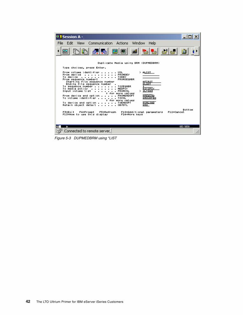
Figure 5-3 DUPMEDBRM using *LIST
42 The LTO Ultrium Primer for IBM eServer iSeries Customers

Chapter 6. Configuring, using, managing LTO drives for the iSeries server
This chapter explains how to configure Ultium tape drive models and the iSeries server for connectivity in an iSeries installation. This chapter also discusses usage and management options that are offered separately from OS/400.
6
© Copyright IBM Corp. 2002. All rights reserved. 43

6.1 Configuring the iSeries for the LTOUnlike some server solutions, there are no device drivers that need to be installed on the iSeries server to support the Ultrium tape devices. The support for these external tape drives is inherent in OS/400 and iSeries microcode as part of any iSeries configuration.
Verify that the QAUTOCFG system value is set to 1. The required device descriptions are then created automatically during a system Initial Program Load (IPL).
Alternately you can use the Work with Hardware Resource (WRKHDWRSC) command to manually configure the device. Start by displaying the hardware resources:
WRHDWRSC *STG
On the resulting display, find the resource name to assign to the new tape drive. Then use the Create Tape Device command to create the new device:
CRTDEVTAP DEVD(TAPXX) TYPE(*RSRCNAME) MODEL(*RSRCNAME) + RSRCNAME(resource name)
The 3580 is not listed as a Device tape for the CRTDEVTAP command. Use the *RSCNAME keyword to specify the device type. Refer to Information APAR II12621 in the Software Knowledge database, which has further information on configuring OS/400 and Ultrium tape devices.
If you are configuring for the IBM 3581 Ultrium Tape Autoloader or IBM 3583 Ultrium Scalable Tape Library, and the required media library and tape device description is not created after an IPL or the reset of IOP, use the Create Media Library Device Description (CRTDEVMLB) and Create Tape Device (CRTDEVTAP) commands to create the media definition object and tape device description. This ensures a media density of ULTRIUM1 is created.
If you use BRMS to manage the drives, use the Initialize BRMS (INZBRM) command to add the device to BRMS:
INZBRM OPTION(*device)
6.2 Configuring the LTO drive as an alternate IPL deviceWhen you connect a SCSI-attached 3580 or 3581, 3583, and 3584 and want to use the drive as an alternate IPL device, set the SCSI address of the tape device to 0.
Alternate IPL is not supported with Fibre Channel attached tapes. The Alternate Installation Device function is used for Fibre Channel attached devices. With Boot Manager, the system is loaded from a CD or DVD device. After the system is booted, the system restore continues from the save tape on the specified attached tape device.
For more details, refer to Backup and Recovery, SC41-5304.
6.2.1 Setting SCSI address for the IBM 3580 Ultrium Tape DriveThe SCSI ID is a unique address that identifies the 3580 Tape Drive to the iSeries server. SCSI IDs range from 0 through 15. The priority of SCSI IDs is 7, 6, 5, 4, 3, 2, 1, 0, 15, 14, 13, 12, 11, 10, 9, 8 (listed from higher to lower).
Here are some considerations for setting the SCSI ID of the 3580:
� The 3580 is shipped with the SCSI address set to 0.� Do not select an ID that is already in use by any device on the same SCSI bus.
44 The LTO Ultrium Primer for IBM eServer iSeries Customers

� Do not select the SCSI ID of the SCSI host adapter card.� The priority of this ID is usually higher than any device on the SCSI bus. � The SCSI ID for the host adapter is typically set to 7.
To set the SCSI ID on the 3580, follow these steps:
1. Locate the SCSI address switch at the rear of the 3580 Tape Drive.
2. With a small, pointed object (such as a ballpoint pen), press the + or - push button until the ID that you want displays on the switch.
3. To activate the new SCSI ID, power off the 3580 drive and then power it on again.
Refer to IBM 3580 Ultrium Tape Drive Setup, Operator, and Service Guide, GA32-0415, for more information.
6.2.2 Setting the SCSI address for the IBM 3581 Ultrium Tape AutoloaderThe 3581 Tape Autoloader consists of two SCSI devices: the autoloader and the drive. The default settings for the SCSI IDs are LdR Id 1 (for the autoloader) and dRV Id 3 (for the drive). Depending on your requirements, you may need to change the SCSI ID default settings for your installation.
Here are some considerations for setting the SCSI ID of the 3581:
� Do not select an ID that is already in use.
� Do not select the SCSI ID of the SCSI host adapter card. The priority of this ID is usually higher than any device on the SCSI bus. Generally, the SCSI ID for the host adapter is set to 7.
� When setting the SCSI ID, unless you choose another operation, the 3581 Tape Autoloader times out 150 seconds after each operation and LdR REAdY appears in the message display.
� If you are using an iSeries server and you want to boot from the autoloader’s drive, set the SCSI ID of the drive to 0.
To set or change the SCSI ID setting on the 3581, perform the following steps:
1. Repeatedly press the MODE button until SET SCSI appears on the message display.
2. Press the SELECT button three times. The message LdR SCSI displays to indicate that you are changing the SCSI ID of the autoloader (rather than the SCSI ID other drive).
Refer to IBM 3581 Ultrium Tape Autoloader Setup, Operator, and Service Guide, GA32-0412, for more information.
6.2.3 Setting the SCSI address for the IBM 3583 Ultrium Scalable Tape LibraryThe 3583 Tape Library consists of up to seven SCSI devices: the library and up to six drives. The default settings for the SCSI IDs are 6 for the library and 0 through 5 for the drives.
Here are some considerations for setting the SCSI ID of the 3583:
� Do not select the SCSI ID of the SCSI host adapter card.
� On the SCSI bus, any initiator (such as a host adapter card) that needs to communicate with the library must have its SCSI ID set from 0 to 7.
� The SCSI ID of the SCSI host adapter card is typically higher than any device on the SCSI bus.
Chapter 6. Configuring, using, managing LTO drives for the iSeries server 45

To change the SCSI ID setting for the 3583 Tape Library, perform the following steps:
1. Press the button below the Up or Down softkey until the ID that you want displays in the SCSI ID: NEW field.
2. Press the button below the Next softkey until the OK softkey displays.
3. Press the button below the OK softkey to accept the new ID.
4. To activate the new SCSI ID, power off the 3583 drive and then power it on again.
Refer to IBM 3583 Ultrium Scalable Tape Library Setup and Operator Guide, GA32-0411, for more information.
6.2.4 Setting the SCSI address for the IBM 3584 UltraScalable Tape LibraryTo display the SCSI IDs of tape drives that use LVD or HVD interfaces, the SCSI IDs of control ports, or the Loop IDs of Ultrium Tape Drives that use Fibre Channel interfaces, use one of the following methods.
� The 3584 Tape Library Specialist Web tool� The Operator Panel
Refer to IBM 3584 UltraScalable Tape Library Planning and Operator Guide, GA32-0408, for further information.
6.3 Using LTO drives on the iSeries serverThe most modern tape devices today are installed as a part of a tape automation system – a tape library. This is witnessed by the year-to-year significant increase in the number of installed tape libraries to fulfill semi-online storage opportunities. An increase in the number of installed tape libraries is certain in the years to come.
Using tape as a part of tape library has opened new ways of looking at tape as a storage medium. It can be considered a large capacity semi-online storage repository. In turn, this creates opportunities for new applications that would not be feasible due to cost or copy.
An Automated Tape Library (ATL) is an industry term for a product's name. The tape library peripherals known as ATL, which are supported by the iSeries product line, include the 3583, 3584, 3570, 3574, and a 3494 with a 3490 or 3590.
Media Library (MLB) is the device name given to ATLs when they attach to the iSeries server. It is the iSeries device configuration term for a type of device.
With automatic configuration active (when the QAUTOCFG system value is set to 1), an MLB device is created any time a device reports the presence of a media changer or robot for moving media. Autoloaders with random mode (for example, the 3581, 3590, or 3490 Fxx) are configured as an MLB. Tape libraries (ATLs) are also configured as MLB.
This section explains how to manage your LTO drive as an ATL with OS/400 commands or with the support offered with BRMS.
6.3.1 OS/400 media library commandsThe Work with Media Library Status (WRKMLBSTS) command is used to configure and manage media libraries. When you run this command, the Work with Media Library Status display is displayed, which shows status information for the descriptions of library
46 The LTO Ultrium Primer for IBM eServer iSeries Customers

configurations. All associated drive resources are shown for each library device description selected.
Options available on the Work with Media Library Status display are to:
� Vary the drive online or offline� Work with device descriptions
For tape media library devices, options are also available to allocate and reset drive resources within the device.
Figure 6-1 shows the options that are available from the Media Library commands menu.
Figure 6-1 OS/400 Media Library commands
6.3.2 Parallel save and restoreBeginning with OS/400 V4R4, simultaneous restore operations can be performed using more than one save device simultaneously. To restore data in a parallel operation, the data restored should be saved in a parallel save operation format.
BRMS supports parallel save and restore operations, which offer automated availability and recovery support. For control group processing, a parallel save or restore request requires libraries and objects in libraries to be entries in the control group.
Refer to Backup and Recovery, SC41-5304, for details about using parallel save and restore as supported by OS/400. You should also refer to Backup Recovery and Media Services for OS/400: A Practical Approach, SG24-4840, for using parallel save and restore as automated with BRMS.
This section uses a 3584 UltraScalable Tape Library and logical library with two drives, and BRMS to illustrate the parallel save and restore function. Figure 6-2 illustrates the values specified for the parameters of a Change Backup Control Group Attributes operation to create a control group to support parallel saves.
Change Device Desc (Media Lib) Change Job MLB Attributes Create Device Desc (Media Lib) Delete Device Description Work with MLB Resource Queue Work with Media Library Status
Category Commands Cartridge Commands Device Commands
Device Description Commands
Configuration Media Management
GO CMDMLB
Chapter 6. Configuring, using, managing LTO drives for the iSeries server 47

Figure 6-2 Change Control Group Attributes
A media policy is set to support parallel operations for full and incremental backups. The Minimum resources and Maximum resources parameters specify the number of devices to be used for the save and restore operations controlled by the control group (GROUP1 in our example).
Set the Parallel device resources parameters to *AVAIL to use any available device for the save or restore operation. Using *AVAIL avoids the need to change your policies and group attributes, if you have to change your library configuration by adding or removing a drive. This allows BRMS to use any available resources.
To work with categories that cartridge identifiers can be assigned to in a media library device, all cartridge identifiers in a media library must be assigned to a category. System-supplied categories include *INSERT, *SHARE400, *NOSHARE, *IPL, *NL, and *EJECT. You can also define your own categories.
6.3.3 BRMS media library commandsTo access commands used for media libraries, go to the BRMS main menu (GO BRMS). Then select option 1 to display the tasks related to Work with media libraries (WRKMLBBRM). Select option 9 to perform tasks related to media library information. These tasks include:
Attention: If a Media Library Device (MLB) is specified as the backup device, and the required resource is not available, the save or restore command waits for the MLB to become available for a time period specified by the user. The wait time is determined by the value specified for the INLMNTWAIT parameter on the *MLB device description.
If a *TAPE device is specified as the backup device and the required resources are not available, the command fails.
Note: Parallel saves do not support the transfer of save files to tape.
48 The LTO Ultrium Primer for IBM eServer iSeries Customers

� Hold or release the media library � Work with MLB media � Add or display MLB media � Display MLB status
Figure 6-3 shows the hierarchy of and functions that are available with the BRMS Media Library commands.
Figure 6-3 BRMS media library menu structure
6.4 Configuring the LTO to attach to the iSeries serverThis section explains how to configure and attach the LTO tape drives to the iSeries. Contact your IBM representative to order the LTO drive firmware cartridge with the latest firmware to support connectivity to the iSeries server.
6.4.1 The IBM 3580 Ultrium Tape DriveRefer to IBM 3580 Ultrium Tape Drive Setup, Operator, and Service Guide, GA32-0415, for setup instructions for the 3580.
6.4.2 The IBM 3581 Ultrium Tape Autoloader The 3581 Ultrium Tape Autoload operates in two modes:
� Random access mode� Sequential access mode
In random access mode, the 3581 Tape Autoloader allows the server’s application software to select any data cartridge in any order.
In sequential access mode, the 3581 Tape Autoloader’s firmware predefines the selection of the cartridges. After initialization, the firmware causes the autoloader to load the first cartridge found (counting from 1 through 7) into the drive. After the server’s application software fills this cartridge with data and issues an unload command, the autoloader returns the cartridge to its storage slot and loads the next cartridge in order.
BRMS Backup Recovery and Media Main menu
Media management
Media Management Work with media libraries
Change Hold Display Release Work with MLB media Display MLB mediaDisplay MLB status
Add MLB media
Chapter 6. Configuring, using, managing LTO drives for the iSeries server 49

If the autoloader is switched from random to sequential mode, or from sequential to random mode, you have to reset the IOP to apply the change to the SCSI configuration.
Set the SCSI address to 0 if the 3581 Ultrium tape Tape Autoloader is to be used as an alternate IPL device (D-mode IPL).
To configure your 3581, refer to IBM 3581 Ultrium Tape Autoloader Setup, Operator, and Service Guide, GA32-0412.
Barcode labelsTape cartridges that are processed by the 3581 Tape Autoloader must have a barcode label only if you install a barcode reader. Refer to IBM 3581 Ultrium Tape Autoloader Setup, Operator, and Service Guide, GA32-0412, for information on using barcode labels on tape cartridges.
6.4.3 The IBM 3584 UltraScalable Tape Library The IBM 3584 UltraScalable Tape Library can be configured in one of two ways:
� From the Operator Panel� From the Web
Using the 3584 Tape Library operator functions panel From the 3584 Operator Panel, you can perform all operations by using the up and down arrows and the Enter key. Figure 6-4 illustrates the hierarchy of the available 3584 Tape Library Operator Panel functions.
Note: If the 3581 is attached to the iSeries server with a #2729 PCI Magnetic Media Controller or the #2749 PCI Ultra Magnetic Media Controller, other IOAs can be attached to the same IOP. Resetting the IOP will impact the other devices on that IOP.
50 The LTO Ultrium Primer for IBM eServer iSeries Customers

Figure 6-4 3584 Tape Library Operator Panel functions
For Service Functions, see the IBM Ultrium 3584 Tape Library Maintenance Information Guide, SA37-0426, for more details.
The 3584 UltraScalable Tape Library can be configured with or without partitions. First, the elements are discovered (such as frames, cartridge storage slots, drives, and I/O slots). The physical configuration is displayed with a prompt for confirmation of the configuration.
If you choose to configure without partitions, all physical devices are assigned to one logical library.
For more details, refer to IBM 3584 UltraScalable Tape Library Planning and Operator Guide, GA32-0408.
Configuring the 3584 Tape Library with partitions A partition must have one drive and at least two slots. You can partition the 3584 UltraScalable Tape Library into multiple logical libraries by using one of two methods:
� Using labels� From the Operator Panel
Configuring the 3584 Tape Library by using labelsThis method requires that you manually label the storage elements (storage slots and drives) that you want in each logical library, and then select Configure Library to identify them to the library. If you use this method, you can view the boundaries of your logical library whenever you open the front doors of the Ultrium drive. You can configure up to 10 logical libraries with labels.
Operator Panel
Main Menu Library Manual Settings Usage Vital Services Status Operations Statistics Product Data
Accessor Status
Drive StatusControl Port
StatusI/O Station
StatusStorage Slot
StatusCartridge Locations
Inventory Library Inventory Frame
Insert, Remove Move cartridge
Clean operations
Accessor usageDrive Usage
Cleaning Cartridge Usage
Library VPDNode Card VPD
Control Port VPD
Configuration Cleaning SCSI/Loops World Wide Port Names Control Network Date/Time Sounds Mode IDs World Wide Node Names Paths
Display ConfigurationConfigure LibraryAdvanced Configuration
Enable AutomaticDisable Automatic
Displays SCSI/Loop IDsChange SCSI/Loop IDs
Display Control PathsChange Control Paths
SNMP Ethernet Web Server
Enable/Disable SNMPDisplay/Change IP AdressDisplay/Change Community NameDisplay/Change Remote Port Send Test Trap
Display SettingsDisable SettingsEnable DHCP SettingsEnable/Change Settings
Enable/Change PasswordDisable Password
Chapter 6. Configuring, using, managing LTO drives for the iSeries server 51

Configuration from the 3584 Tape Library Operator Panel You can use the Operator Panel to configure the library. Press the up or down keys and Enter to select the desired functions. Pressing up, down, and Enter enables you to navigate through the operator menu.
Figure 6-5 shows the menu structure of the 3584 Operator Panel.
Figure 6-5 Configuring a logical library with the Operator Panel menu
For further configuration information, refer to IBM 3584 UltraScalable Tape Library Planning and Operator Guide, GA32-0408.
6.5 Enhanced management capabilities for the 3583 and 3584Centralized management for the setup, changing, and controlling of storage units is an important function in a SAN environment. This section describes tools available to the iSeries customer for managing the 3583 and 3584 Ultrium tape drives in a SAN installation.
6.5.1 StorWatch Specialist Support for LTO 3583 and 3584 libraries Operator Control Panel functions are handled through the network, including microcode downloads.
The tape management capabilities of the StorWatch Specialist tool includes:
� Remote management capability via a Web browser� SNMP monitoring capability
Settings
Configuration
Advanced Configuration
Searching for installed devices; may take approximately 2 minutes to discover the physical configuration. Displays the current
physical configuration.
Do you want to commit the new physical configuration?
Ensure that any physical configuration changes are completed before you continue.
Set up any logical library configurations.
Main Menu
52 The LTO Ultrium Primer for IBM eServer iSeries Customers

6.5.2 Remote Management UnitYou can manage your 3583 Tape Library with the Remote Management Unit (RMU). RMU allows you to have access to the 3583 Tape Library over a network. With RMU you have access to all available functions without a dedicated server or separate software. In addition, when you use the RMU tool with the StorWatch Specialist, you can perform the following functions remotely:
� Check system status, library and drive conditions, and firmware levels� Perform all library operator panel functions� Update firmware in the RMU, the library controller, and the tape drives� Retrieve the library command and error logs and the RMU error log� Configure changes, such as network, users, date, and time� Access online documentation about the library
Remote Management Unit is available only for the IBM 3583 Ultrium Scalable Tape Library.
6.5.3 Managing the 3584 with Web SpecialistThe 3584 Web Specialist is designed for easy management of the 3584 UltraScalable Tape Library. The Web Specialist application provides you menus and a navigation aid. You can manage your 3584 library from the Web with the available Web Specialist tools.
To use the Specialist interface, perform the following steps:
1. Have the Ethernet Internet Protocol (IP) address of the other frame to which you want to connect (for example, http://10.1.1.e).
2. Access Internet Explorer 5.0 (or higher) or Netscape Navigator 4.7 (or higher).
3. Type the Ethernet IP address on the URL line of the browser and press Enter.
Figure 6-6 shows an overview of the functions that are available with the 3584 Web Specialist.
Chapter 6. Configuring, using, managing LTO drives for the iSeries server 53

Figure 6-6 3584 Web Specialist function overview
Figure 6-7 shows the Physical Library page. This page has two panels: a Navigation Area (as indicated by 1) and a functions area (as marked with 2).
Physicallibrary
Service
Manual operations
Settings
Logicallibrary
CartridgesI/O StationAccessor
Node CardsStorage Slots
CartridgesDrives
Storage Slots
Inventory CartridgesClean Drive
Move CartridgeInsert Cleaning Cartridge
Remove Cartridge
Change Security SettingsConfigure Library
View World Wide Name Change Control Paths
Change Cleaning ModeChange Date and Time
Change Drive SCSI Loop IDChange Control Path SCSI ID
For more information, refer to IBM Ultrium Tape Library
Maintenance Information Guide
54 The LTO Ultrium Primer for IBM eServer iSeries Customers

Figure 6-7 3584 Web Specialist
Each area marked in Figure 6-7 is explained here:
1 Navigation area: This section has a list of functions that you can perform. When you select a function, a list of subfunctions appears.
2 Function area: This section displays the output of the function that you selected. For example, if you click the Physical Library function, these functions appear:
– Cartridges– I/O Station– Accessor– Node Cards– Storage Slots
3 The title at the top of the page helps you to identify which function you are using.
4 Click the Help link to open a Help panel.
Certain library functions can be restricted to authorized users through password protection. The administrator user password is disabled when IBM ships the library from the factory. The password is set from the Settings options of the main menu. After you enable the password, the following functions are password protected:
� Enable or disable control paths� Change drive SCSI or Loop IDs� Clean a drive� Configure logical libraries� Move cartridges� Remove cartridges
1
2
3
4
Chapter 6. Configuring, using, managing LTO drives for the iSeries server 55

� Import data or scratch cartridges (importing cleaning cartridges is not password-protected)
� Inventory the library� Change the cleaning mode� Update library and drive firmware� Update control port firmware� Download logs� Change date and time� Change the 3584 Specialist Web interface password� Change control port SCSI IDs
For more details, refer to IBM 3584 UltraScalable Tape Library Planning and Operator Guide, GA32-0408.
Configuration with the 3584 Web Specialist To use the 3584 Tape Library Specialist Web interface, perform the following steps:
1. Type the Ethernet IP address on the URL line of the browser and press Enter. The Introduction page is displayed.
2. Click Settings Library Configuration. Click the Configuration wizard link and follow the instructions on the page.
Figure 6-8 shows an example page from the Configuration wizard.
Figure 6-8 Configuration wizard
3. Click the Advanced configuration option. Follow the instructions on the page to specify one or more logical libraries and their attached physical devices (such as cartridge storage
56 The LTO Ultrium Primer for IBM eServer iSeries Customers

slots and drives) and accept the configuration of the logical libraries. See Figure 6-9 for an example.
Figure 6-9 3584 Web Specialist Advanced Configuration Menu
4. Click Next to continue.
Figure 6-10 illustrates the configuration of a logical library. As noted in Figure 6-10 (see 1 and 2) the LTO library has three drives and 21 storage slots.
Chapter 6. Configuring, using, managing LTO drives for the iSeries server 57

Figure 6-10 Logical library configuration
The number of storage slots depends on your save strategy policy.
If you use several drives, you have to enable the control paths of those drives. The status of the control path can be required. You cannot change the required status if the other drives are disabled. To change the status to enabled, click the Settings menu.
As illustrated in Figure 6-11, all control paths of Frame 1 are displayed. Some are shown as required, and others are shown as enabled or disabled. If you configure a logical library with only one drive, the control path default status is required.
In the example in Figure 6-11, the logical library has three SCSI drives. Their addresses are set from 1 to 3.
1
2
58 The LTO Ultrium Primer for IBM eServer iSeries Customers

Figure 6-11 Changing Control Paths
To change the status of one of the drives, click the radio button to select the control paths and then click the Change button.
6.6 LTO storage management toolsTraditionally, storage management was the responsibility of the host server to which the storage resources are attached. With SAN, the focus has shifted away from individual server platforms, making storage management independent of the operating system. This way we can achieve greater flexibility by managing shared resources across the enterprise SAN.
The following software management tools are relevant for LTO devices connected to iSeries in a SAN network:
� Tivoli Storage Manager (TSM)� StorWatch Specialist for the 3584 Tape Library
Tip: When you configure the 3584 UltraScalable Tape Library with the 3584 Web Specialist, you can change and then lose the latest configuration. Document the present configuration before you start the configuration process.
Note: When you do not have a labeled configuration, you cannot view the boundaries of the logical library.
Chapter 6. Configuring, using, managing LTO drives for the iSeries server 59

For a description of TSM, see 6.7.2, “Automating storage management with Tivoli Storage Management” on page 61.
For a description of how to manage a 3584 Tape Library with StorWatch Specialist, see 6.5.3, “Managing the 3584 with Web Specialist” on page 53.
6.7 iSeries software tools for tape automationIn an open-systems environment that includes an iSeries server, the solution for backup, recovery, media, and storage management is TSM. BRMS remains the IBM strategic solution for managing backup, recovery, media, and storage in an iSeries environment. Together, BRMS and Tivoli Storage Management provide a comprehensive storage management solution.
6.7.1 Automating storage management with BRMS/400With Backup Recovery and Media Services for OS/400 (BRMS/400), you can plan, control, and automate the backup, recovery, and media management for iSeries server.
We strongly recommend that you use BRMS/400 for tape library automation. Without using this software, you have to write extensive CL programs with APIs to control the LTO Tape Library and its media management.
BRMS functions that are advantageous for automated tape management include:
� Operations and management with easy commands and graphical user interface� Good control of the save/restore procedures � Complete media management for one or more iSeries servers
And BRMS functionality is continually enhanced. For example, plug-ins to iSeries servers are supplied with V5R1 (known in V5R2 as iSeries Navigator).
The product number for BRMS/400 is 5722-BR1 (V5R1 and V5R2). The base offering includes the following basic functions:
� Media management for a single system� Save and restore capabilities� Management for tape libraries� Save to TSM (formerly known as ADSM) Server
Beginning with the packaging structure of BRMS at V5R1, two optional features of BRMS are available:
� BRMS/400 Network feature (installs as Option 1 of BRMS)
– Media management for multiple iSeries servers– Central Management of all save policies
� BRMS/400 Advanced Functions (installs as Option 2 of BRMS)
– Hierarchical Storage Management (HSM):
• Archive• Dynamic retrieval• Migration
60 The LTO Ultrium Primer for IBM eServer iSeries Customers

You can find additional information about BRMS/400 in:
� Backup and Recovery, SC41-5304� Backup Recovery and Media Services for OS/400: A Practical Approach, SG24-4840
6.7.2 Automating storage management with Tivoli Storage Management Tivoli Storage Manager provides powerful tools for storage resource management. This helps you efficiently and comprehensively handle the retention, archiving, and retrieval of vital business records. You can use TSM to automate many critical data-protection processes, including the operational backup and restore of data (of both system resources and user data), as well as to implement disaster-recovery procedures.
A Tivoli Storage Manager server serves to save and restore client data in a network. The iSeries server is a supported server for TSM. IBM Tivoli Storage Manager Server for OS/400 (product number 5698-ISM), TSM V5.1, then enables the use and sharing of an attached IBM LTO Tape Library.
TSM operates in the Portable Application Environment (PASE) environment on OS/400. PASE is available from OS/400 V5R1 onward.
The basic functions of IBM Tivoli Storage Manager include:
� Data backup and restore, automatically and policy driven� Managed data archive and retrieve� Protection for 24 x 365 business-critical applications with online backup capabilities for the
most used databases
You can find additional information about IBM Tivoli Storage Manager on this Web site:
http://www.tivoli.com/products
6.7.3 Integrating TSM with BRMSTo create a comprehensive, automated process for data backup and recovery in a heterogeneous computing environment that includes iSeries, you can integrate the functionality of the TSM and BRMS applications.
To implement this solution, start by obtaining a set of Tivoli Storage Manager APIs for BRMS. These APIs make it possible to create a BRMS application client to a TSM server running on a different platform. The addition of the BRMS application client software lets you use BRMS to save user data to your TSM server across a network. Meanwhile, iSeries system data is still saved to a local tape device using BRMS or OS/400 commands. OS/400 software includes a job scheduler that can be used to automatically schedule BRMS operations.
Integrating BRMS and TSM is the recommended approach when iSeries servers represent a substantial portion of your computing infrastructure. BRMS is a simple way to cost-effectively back-up large amounts of system data. And TSM complements the primary backup/recovery strategy by making it simple to manage the backup and recovery of user data from the iSeries system, as well as data from other systems and platforms attached to the network.
For more information on TSM, refer to A Practical Guide to Implementing Tivoli Storage Manager on AS/400, SG24-5472.
Note: We recommended that you do not save a large amount of OS/400 data volumes with the Tivoli Storage Manager OS/400 Client API. In many cases, it is best for TSM and BRMS/400 to work in complement for an effective performing solution.
Chapter 6. Configuring, using, managing LTO drives for the iSeries server 61

6.8 LTO backup throughputIt is important to manage the length of time required for the “save window”. This section describes the performance of backup to an LTO tape devices in two scenarios: TSM and BRMS.
Disk performance and file size affect the performance of backup operations. To illustrate this fact, assume you backup 10KB of small files. If your disk drive transfers at 10 MB/sec, it takes 1ms to transfer the 16KB file. Then the disk drive does a multi-millisecond search and a multi-millisecond seek before it is ready to read the next file. In this case, the disk drive spends 80 - 90% of its time moving the drive actuator, and a very small percentage of time actually reading data. As one would expect, data cannot be written to tape any faster than it can be read from disk. Figure 6-12 illustrates this statistic.
Figure 6-12 LTO TSM backup throughput
Different tape operations have different performance characteristics. On IBM tape drives, backup and recovery normally perform similarly. Reclamation is slower than large file backup because of the substantial amount of tape movement involved.
As you can see from Figure 6-12, and the previous TSM charts, all major backup applications provide good performance for large file backups. Different applications have different mechanisms to mitigate the performance impact of backing up small files.
Figure 6-13 shows the different workloads. TSM, for example, recommends sending small file (less than 100 MB) to a disk storage pool and then migrating the data to tape.
Tape reclamation: This is a TSM process that deletes expired files on tape and consolidates the remaining unexpired files to other tape volumes. The resulting empty tapes can then be reused.
File size0
10
20
30
40
33.2
5.7
10 KB 64 KB 256 MB
MB
/sec
.
62 The LTO Ultrium Primer for IBM eServer iSeries Customers

Figure 6-13 LTO backup throughput using BRMS
iSeries workload type 0
10
20
30
40
50
38.6
21.7
4.4
NSRC1GB NUMX12GB 16 GB
MB
/sec
Chapter 6. Configuring, using, managing LTO drives for the iSeries server 63

64 The LTO Ultrium Primer for IBM eServer iSeries Customers
Chapter 7. SAN and the iSeries server
A Storage Area Network (SAN) differs from traditional networks because it is constructed from storage interfaces. SANs create new methods of attaching storage to servers. These new methods promise great improvements in both availability and performance.
This chapter introduces SAN and describes how the iSeries server fits into a SAN infrastructure. This chapter also describes the new possibilities that iSeries V5R2 switched fabric support brings to an iSeries LTO customer.
7
© Copyright IBM Corp. 2002. All rights reserved. 65

7.1 SAN and the benefits it brings to the iSeries customerA SAN is similar to a local area network (LAN) and wide area network (WAN) in architecture. It differs in that SANs are intended to pass traffic for storage and storage management only.
A SAN has the potential to offer several major benefits to a business, including:
� Improved performance for backup processes� Sharing of data� Centralized and consolidated storage� Centralized storage management
The additional benefits that SAN brings to an iSeries LTO customer include:
� Sharing of tape devices� Extended distance to storage devices� Performance improvements
This section discusses these additional iSeries benefits.
7.1.1 Sharing tape device among multiple hostsWith Fibre Channel (FC) support on the iSeries server, it is possible to attach more hosts to a single drive via hubs and switches. In the case of an IBM Ultrium Scalable tape library, the connection can be an integrated SAN Data Gateway.
7.1.2 Extended distanceOne of the major drawbacks of SCSI tape drives is the attachment limit of 25 meters. Fibre Channel connection allows an LTO tape drive to be located up to 500 meters from a single iSeries server depending on the fibre being used and also on the data transfer speed. Using cascaded switches, the tape drive can be located up to 12 km from the server.
7.1.3 PerformanceFibre Channel technology provides the potential for faster data rates than earlier tape connection technologies. The actual performance realized, however, depends on the application and data type used.
When planning for tapes attached to iSeries in a SAN infrastructure, the following factors also influence performance and should be taken into consideration:
� Multiple host servers attached to a switch � Multiple tape devices attached to a switch � Zoning � The number of Inter Switch Links (ISLs) when cascading switches
For more information about the performance of fibre attached tapes, refer to the RedDraft IBM ~ iSeries in Storage Area Networks: A Guide to Implementing FC Disk and Tape with iSeries, SG24-6220.
7.2 Fibre Channel architectureSAN solutions use a dedicated network, based primarily (though, not necessarily) on Fibre Channel architecture. Fibre Channel is a technology standard that allows data to be
66 The LTO Ultrium Primer for IBM eServer iSeries Customers

transferred from one network node to another at high speeds. Fibre Channel is a reliable, high-performing solution for information storage, transfer, and retrieval. Current implementations transfer data at a rate of 100 MB/sec. and 200 MB/sec.
In a Fibre Channel network, the interconnections between nodes are mainly based on fibre optics.
A Fibre Channel network can be composed of many different types of interconnected entities, including switches, hubs, and bridges. Refer to the following section for more information.
7.3 SAN componentsThere are three main categories of SAN components:
� SAN servers� SAN storage � SAN interconnects
SAN serversThe SAN server infrastructure includes server platforms, such as iSeries servers, UNIX and its various types, Windows NT, and mainframes.
SAN storage devicesThe SAN storage infrastructure includes storage devices and provides network availability, data accessibility, and system manageability.
iSeries implementations use SAN connections to the following storage devices:
� IBM TotalStorage Enterprise Storage Server (ESS, or commonly referred to as Shark)� IBM 3590 TotalStorage Enterprise Tape System� IBM 3583 Ultrium Scalable Tape Library� IBM 3584 UltraScalable Tape Library
SAN interconnectsThe first element that must be considered in any SAN implementation is the connectivity of storage and servers using technologies such as Fibre Channel. The fabric in a Fibre Channel can be as simple as a single cable connecting two devices. However, most often, it is a more complex network in using switches, hubs, and gateways.
Figure 7-1 shows these SAN components.
Tip: This Redpaper refers to the 3583 Ultrium Scalable Tape Library as 3583 Tape Library, and the 3584 UltraScalable Tape Library as the 3584 Tape Library.
Chapter 7. SAN and the iSeries server 67

Figure 7-1 SAN components
The fabric components employed in a typical SAN implementation are described in the following section.
7.4 SAN parts and how they relate to iSeriesThis section describes various items that may be used to build a SAN. This includes physical components, protocols, and concepts. The information that relates specifically to the iSeries is marked with a shaded box in the left margin.
7.4.1 Nodes, ports, and linksThe terms that are used to describe the physical components of a SAN infrastructure are:
� Node: The source or destination for data being transported
� Port: The hardware entity within a node that performs data communications over the Fibre Channel
� Link: A connection that consists of fibre between two Fibre Channel ports that transmits and receives
7.4.2 Topologies Fibre Channel provides two physical interconnection topologies:
� Direct attach: This topology consists of one connection between two nodes.
� Fabric: This topology connects one to many nodes through SAN components.
68 The LTO Ultrium Primer for IBM eServer iSeries Customers

By having more than one interconnection option available, a SAN designer can choose the topology that is best suited to the customer’s requirements.
Fibre Channel provides three transport topologies (communication methods):
� Point-to-point (direct attach)� Arbitrated loop� Point-to-point (switched fabric)
Point-to-point (direct attach)Point-to-point is the simplest communication method in Fibre Channel. It runs in a direct-attach physical topology. Point-to-point is used when there are exactly two nodes, and future expansion is not predicted. The connected nodes use the total bandwidth of the link.
The point-to-point direct attach communication runs on direct attach physical topology. Point-to-point direct attach transport topology is shown in Figure 8-2.
Figure 7-2 Point-to-point (direct attach)
By having more than one interconnection option available, a SAN designer can choose the topology that is best suited to the customer’s requirements.
Arbitrated loopArbitrated loop is a uni-directional ring topology that supports up to 126 interconnected nodes. Each node passes data to the next node in a loop, until the data reaches the target node. All nodes share the Fibre Channel bandwidth. Devices must arbitrate for access to the loop. Arbitrated loop transport topology can be public or private.
Arbitrated loop transport topology runs on direct attach and fabric physical topologies. Arbitrated loop transport topology is supported by iSeries servers running OS/400 V5R1 and V5R2. An arbitrated loop is shown in Figure 8-3.
Server
Storage
Important for iSeries
Chapter 7. SAN and the iSeries server 69
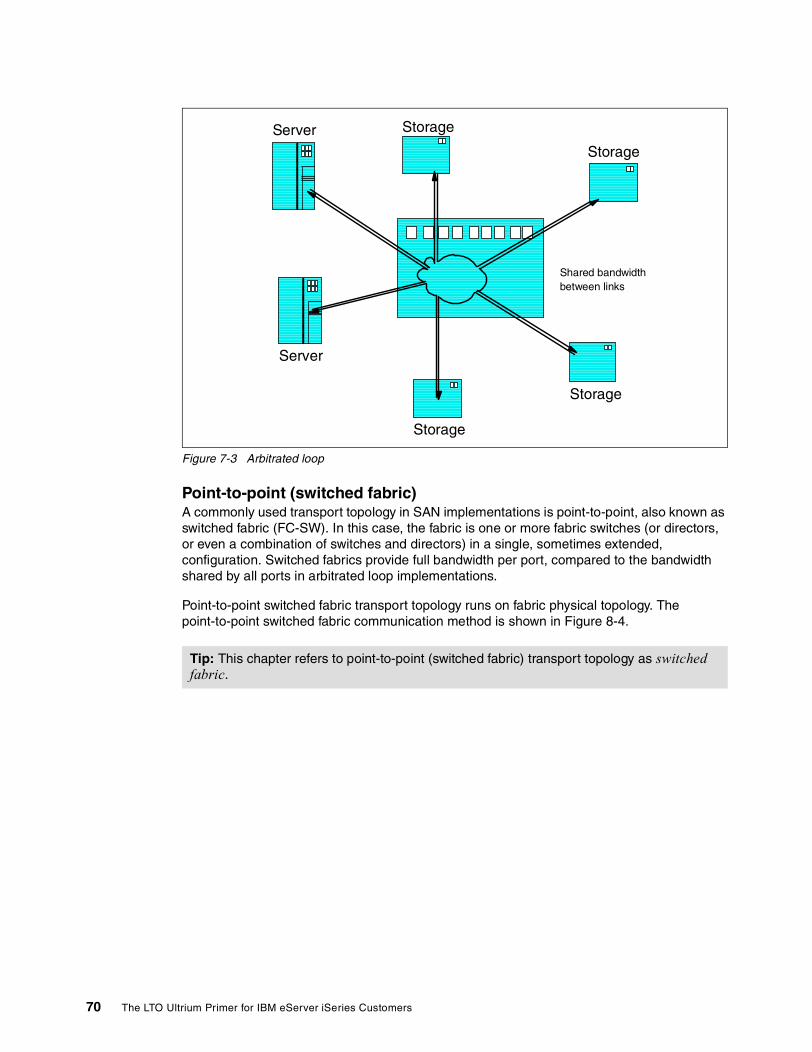
Figure 7-3 Arbitrated loop
Point-to-point (switched fabric)A commonly used transport topology in SAN implementations is point-to-point, also known as switched fabric (FC-SW). In this case, the fabric is one or more fabric switches (or directors, or even a combination of switches and directors) in a single, sometimes extended, configuration. Switched fabrics provide full bandwidth per port, compared to the bandwidth shared by all ports in arbitrated loop implementations.
Point-to-point switched fabric transport topology runs on fabric physical topology. The point-to-point switched fabric communication method is shown in Figure 8-4.
Tip: This chapter refers to point-to-point (switched fabric) transport topology as switched fabric.
Server
Server
Storage
Storage
Storage
Storage
Shared bandwidth between links
70 The LTO Ultrium Primer for IBM eServer iSeries Customers
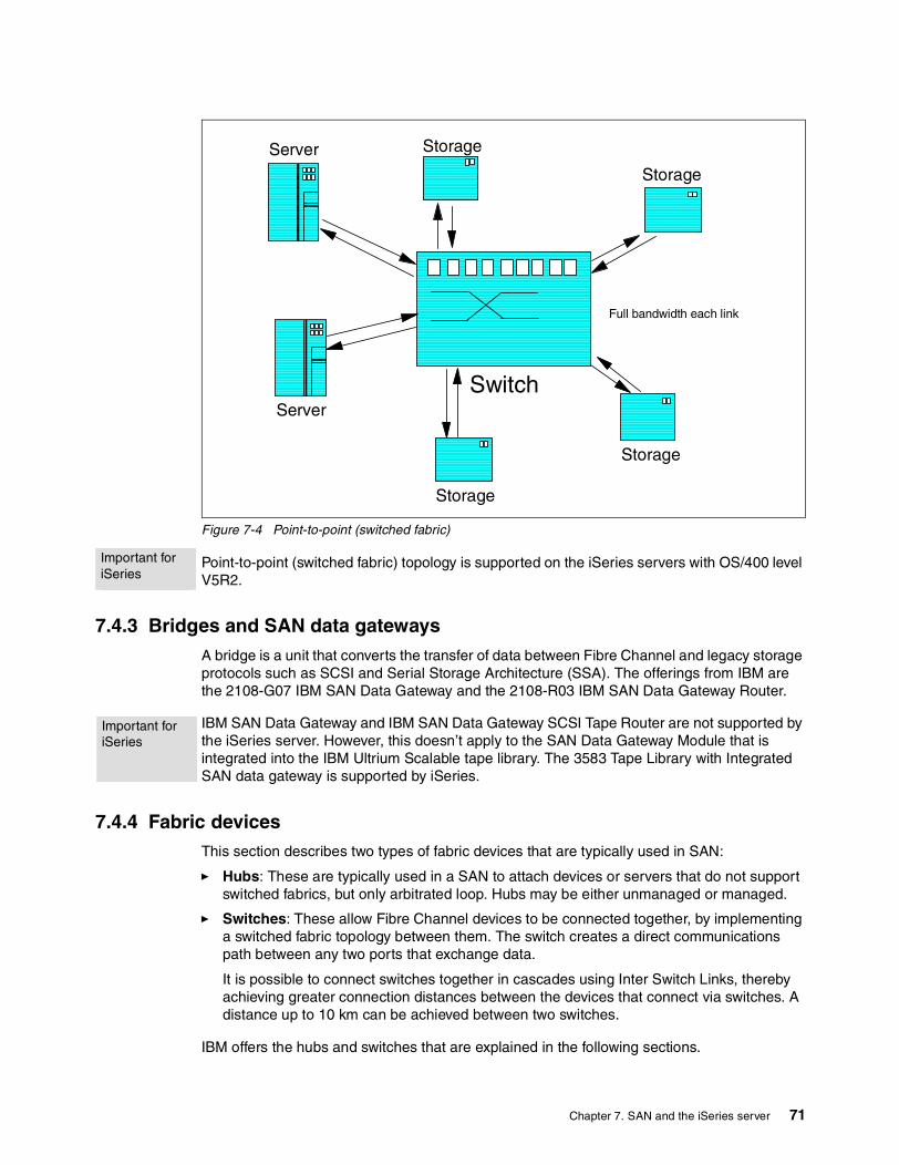
Figure 7-4 Point-to-point (switched fabric)
Point-to-point (switched fabric) topology is supported on the iSeries servers with OS/400 level V5R2.
7.4.3 Bridges and SAN data gatewaysA bridge is a unit that converts the transfer of data between Fibre Channel and legacy storage protocols such as SCSI and Serial Storage Architecture (SSA). The offerings from IBM are the 2108-G07 IBM SAN Data Gateway and the 2108-R03 IBM SAN Data Gateway Router.
IBM SAN Data Gateway and IBM SAN Data Gateway SCSI Tape Router are not supported by the iSeries server. However, this doesn’t apply to the SAN Data Gateway Module that is integrated into the IBM Ultrium Scalable tape library. The 3583 Tape Library with Integrated SAN data gateway is supported by iSeries.
7.4.4 Fabric devicesThis section describes two types of fabric devices that are typically used in SAN:
� Hubs: These are typically used in a SAN to attach devices or servers that do not support switched fabrics, but only arbitrated loop. Hubs may be either unmanaged or managed.
� Switches: These allow Fibre Channel devices to be connected together, by implementing a switched fabric topology between them. The switch creates a direct communications path between any two ports that exchange data.
It is possible to connect switches together in cascades using Inter Switch Links, thereby achieving greater connection distances between the devices that connect via switches. A distance up to 10 km can be achieved between two switches.
IBM offers the hubs and switches that are explained in the following sections.
Server
Server
Storage
Storage
Storage
Storage
Switch
Full bandwidth each link
Important for iSeries
Important for iSeries
Chapter 7. SAN and the iSeries server 71

3534-1RU IBM TotalStorage SAN Managed HubThe 3534-1RU IBM TotalStorage SAN Managed Hub is supported by iSeries. Refer to 1.3, “Attachment options for the iSeries server” on page 7, to understand the necessary iSeries hardware and software levels.
The 3534-1RU IBM TotalStorage SAN managed hub was withdrawn from marketing effective 16 August 2002. For more information about this managed hub, see the following Web page:
http://www.storage.ibm.com
3534-F08 IBM TotalStorage SAN SwitchThe 3534-F08 IBM TotalStorage SAN Switch provides an eight-port, 2 Gbps solution for building SAN. It can be ordered as IBM TotalStorage Switch F08 Entry Fabric or as IBM TotalStorage Switch F08 Full Fabric. The Full Fabric switch has additional capabilities in cascading and zoning, compared to the Entry Fabric switch.
An IBM TotalStorage SAN F08 Switch is shown in Figure 7-5.
Figure 7-5 IBM TotalStorage SAN F08 Switch
IBM TotalStorage SAN F08 Switch Entry Fabric and Full Fabric is supported by iSeries servers. However, for V5R1 OS/400, a Quickloop RPQ is needed to connect via this switch. Refer to 1.3, “Attachment options for the iSeries server” on page 7, to understand the necessary iSeries hardware and software levels.
2109-F16 IBM TotalStorage SAN SwitchThe 2109-F16 IBM TotalStorage SAN Switch provides 16 ports and a 2 Gbps data transfer. The 2109-F16 IBM TotalStorage SAN Switch is shown in Figure 8-6.
Figure 7-6 2109-F16 IBM TotalStorage SAN Switch
iSeries servers support the 2109-F16 IBM TotalStorage SAN Switch. Refer to 1.3, “Attachment options for the iSeries server” on page 7, to understand the necessary iSeries hardware and software levels.
2109-S08 IBM TotalStorage SAN SwitchThe 2109-S08 IBM TotalStorage SAN Switch provides an eight-port, 1 Gbps solution for SAN.
This switch was withdrawn from marketing effective 13 September 2002.
2109-S16 IBM TotalStorage SAN SwitchThe 2109-S16 IBM TotalStorage SAN Switch provides a 16-port, 1 Gbps solution for SAN. This switch was withdrawn from marketing effective 13 September 2002.
Important for iSeries
Important for iSeries
Important for iSeries
72 The LTO Ultrium Primer for IBM eServer iSeries Customers

The S08 and S16 IBM TotalStorage SAN Switches are supported by iSeries servers. Refer to 1.3, “Attachment options for the iSeries server” on page 7, to understand the necessary iSeries hardware and software levels.
7.4.5 CablingThere are a number of different types of fibre cable that can be used when designing a SAN. For the purposes of our discussion, we separate fibre into two categories:
� Single-mode fibre: Used to carry longwave laser light. With 9 micron diameter and a single mode light source, single-mode fibre support distances up to 10 km.
� Multi-mode fibre: Can be used with shortwave or longwave laser light. However, it is typically used with shortwave light. It can have 50 micron or 62.5 micron diameter. With a 50 micron diameter, it supports distances up to 500 m at a speed of 1 Gbps, and up to 300 m at a speed of 2 Gbps. With a 62.5 micron diameter, it supports distances up to 175 m at 1 Gbps speed, and up to 150 m at a speed of 2 Gbps.
The iSeries server uses shortwave fibre cables for Fibre Channel. However, the distance between an iSeries server and a storage device can be extended to 12 km by using cascaded switches.
Figure 7-6 shows a Fibre Channel cable.
Figure 7-7 A Fibre Channel cable
7.4.6 ConnectorsConnectors are used to connect a fibre to a component. The type of connector used depends on the receptacle into which they are plugged. Some devices use Lucent Connector (LC), and some use Subscriber Connector (SC).
The F08 and F16 IBM TotalStorage SAN Switches use LC connectors. Some older fabric devices use SC connectors. Take this into account when planning cables for SAN.
iSeries Fibre Channel adapters use LC connectors to connect fibre. Figure 7-8 shows an example of an SC connector.
Figure 7-8 SC connector
Important for iSeries
Important for iSeries
Important for iSeries
Chapter 7. SAN and the iSeries server 73

Figure 7-9 shows an example of an LC connector.
Figure 7-9 LC connector
7.4.7 Gigabit Interface Converters (GBIC) and Small Form Pluggables (SFP)Gigabit Interface Converters are laser-based, hot-pluggable, data communications transceivers. They are mainly used in hubs, switches, and gateways. They are typically used for a 1 Gbps data transfer.
Small Form Pluggable optical converters are the next generation of laser-based, optical transceivers, designed for increased distances. They are typically used for a 2 Gbps data rate.
The selection of a GBIC or SFP for SAN interconnection is just as important a consideration as choosing a hub or a switch. You must not overlook this.
A GBIC is shown in Figure 7-10.
Figure 7-10 A Gigabit Interface Converter
An SFP is shown in Figure 7-11.
74 The LTO Ultrium Primer for IBM eServer iSeries Customers
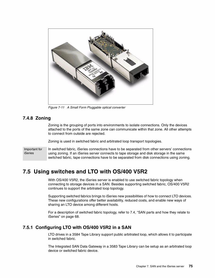
Figure 7-11 A Small Form Pluggable optical converter
7.4.8 ZoningZoning is the grouping of ports into environments to isolate connections. Only the devices attached to the ports of the same zone can communicate within that zone. All other attempts to connect from outside are rejected.
Zoning is used in switched fabric and arbitrated loop transport topologies.
In switched fabric, iSeries connections have to be separated from other servers’ connections using zoning. If an iSeries server connects to tape storage and disk storage in the same switched fabric, tape connections have to be separated from disk connections using zoning.
7.5 Using switches and LTO with OS/400 V5R2With OS/400 V5R2, the iSeries server is enabled to use switched fabric topology when connecting to storage devices in a SAN. Besides supporting switched fabric, OS/400 V5R2 continues to support the arbitrated loop topology.
Supporting switched fabrics brings to iSeries new possibilities of how to connect LTO devices. These new configurations offer better availability, reduced costs, and enable new ways of sharing an LTO device among different hosts.
For a description of switched fabric topology, refer to 7.4, “SAN parts and how they relate to iSeries” on page 68.
7.5.1 Configuring LTO with OS/400 V5R2 in a SANLTO drives in a 3584 Tape Library support public arbitrated loop, which allows it to participate in switched fabric.
The Integrated SAN Data Gateway in a 3583 Tape Library can be setup as an arbitrated loop device or switched fabric device.
Important for iSeries
Chapter 7. SAN and the iSeries server 75

For rules on how to configure iSeries with LTO devices in OS/400 V5R1, refer to the chapter about using Fibre Channel attached tape devices in the RedDraft IBM ~ iSeries in Storage Area Networks: A Guide to Implementing FC Disk and Tape with iSeries, SG24-6220.
Considerations with V5R2 switched fabric topologyUse the following guidelines to configure LTO devices with OS/400 V5R2 in switched fabric topology:
� More than one target per iSeries adapter
In Fibre Channel topologies, the term initiator refers to a host port that initiates requests. The term target (or Responder) refers to a storage device that responds to the initiator’s requests.
With iSeries and LTO devices, an initiator means an iSeries Fibre Channel adapter for tape, and a target means an LTO drive in a 3584 Tape Library, or a fibre port on the integrated SAN Data Gateway
With OS/400 V5R2, you can have multiple targets and up to 16 devices per one iSeries Fibre Channel tape adapter in a Quickloop or switched fabric. We are no longer limited to one target per iSeries adapter, as is the case with OS/400 V5R1.
� Maximum of one path visible to the iSeries for any given device
OS/400 does not support multiple paths to the same device. Configurations at V5R2 must have only one path from an iSeries single system or an iSeries LPAR to any device.
� Extended distance
With OS/400 V5R2 in switched fabric, there can be a maximum of three ISLs connecting cascaded switches. Only one ISL can be 10 km long. This enables you to connect a tape drive to an iSeries server in arbitrated loop or switched fabric, at a distance up to 12 km.
For a description of cascaded switches and hubs, see 7.4, “SAN parts and how they relate to iSeries” on page 68.
� Performance
With OS/400 V5R2, the iSeries #2765 Fibre Channel adapter feature supports a 2 Gbps data transfer. The sustained data rate is 12 Gbps.
7.5.2 Sample scenarios This section describes some scenarios how to connect LTO devices to iSeries. These scenarios used the Fibre Channel switched fabric. Therefore, they cannot be implemented in OS/400 V5R1. They can be only implemented with OS/400 V5R2.
To enable iSeries to access a drive in a 3584 Tape Library, the drive has to have a library-control path enabled.
One iSeries FC adapter connected to two LTO tape drivesIn this scenario, one iSeries FC tape adapter connects via a switch to two FC drives in a 3584 Tape Library. The iSeries server works with a media changer and sees both drives. If one drive fails, the iSeries server can still use the other one. This scenario is shown in Figure 7-12.
76 The LTO Ultrium Primer for IBM eServer iSeries Customers

Figure 7-12 One iSeries FC adapter connected to two LTO drives
Three iSeries servers connected to three LTO tape drives via a switchIn this scenario, three iSeries servers connect to three LTO tape drives in a 3584 Tape Library. Each iSeries server can work with a media changer and sees all three drives. When an iSeries server issues a command to the Tape Library, such as the Save Library (SAVLIB) command, the media changer starts to use any drive that is available. If the drive can be reserved (that is it is not used by another iSeries server), then the system can remove the cartridge and load its own or use the one that is loaded.
This scenario is shown in Figure 7-13.
Figure 7-13 Three iSeries servers connected to three LTO tape drives via a switch
iSeries
FC tape adapter
Switch
3584 Tape Library
FC tape drive
FC tape drive
iSeries #1
FC tape adapter
Switch
3584 Tape Library
FC tape drive
FC tape drive
FC tape adapter
iSeries #2
FC tape adapter
iSeries #3
FC tape drive
Chapter 7. SAN and the iSeries server 77

Three iSeries connected to three tape drives via cascaded switchesThis scenario is the same as the previous one, but this time, two cascaded switches are added to achieve the distance of 12 km between the iSeries server and the 3584 Tape Library. Two switches can be connected via one ISL or via more ISLs for better reliability.
This scenario is shown in Figure 7-14.
Figure 7-14 Three iSeries servers connected to three tape drives via cascaded switches
Two different hosts sharing the same LTO tape driveIn this scenario, we share a tape drive in a 33584 Tape Library between the iSeries and pSeries server or another host. This can be achieved by connecting the two hosts to the tape drive via a switch. In this scenario, we have to make two zones. Each zone contains the port connected to one server and the port for tape connection. The two zones overlap at the port that is connected to the tape drive.
Sharing of a drive by different hosts is managed with a Reserve/Release function. The first host to issue the reserve can use the drive until it issues the release. The other host will receive a response that the drive is reserved elsewhere, until the drive is released by the first host. Once the drive is released, it can be reserved by the other host. For the iSeries server, the Reserve/Release function is a part of the device vary on or off, or the allocate/deallocate function of the library resource.
This scenario is shown in Figure 7-15.
iSeries #1
FC tape adapter
Switch
3584 Tape Library
FC tape drive
FC tape drive
FC tape adapter
iSeries #2
FC tape adapter
iSeries #3
FC tape driveSwitch Switch
ISL ISL
500 m 10 km
ISL
500 m
500 m500 m
Switch
78 The LTO Ultrium Primer for IBM eServer iSeries Customers

Figure 7-15 Two different hosts sharing the same LTO tape drive
7.6 Exploiting SANTape libraries in a SAN solution are expected to play a critical role in consolidating backup and archiving data into one repository. With the extended distance capabilities offered with a SAN solution, the tape repository can be located at the most convenient location within the enterprise.
Another advantage of SAN is LAN-free data movement, which can be done in a Tivoli Storage Management (TSM) environment. With LAN-free movement, the TSM client does not send data via LAN to the TSM server, which would then store data to a tape. Instead, the TSM client reads data from the disks and writes them directly to the tape. This movement is managed by the TSM server. This reduces the traffic through LAN, increasing performance.
For a description of TSM, refer to 6.7.2, “Automating storage management with Tivoli Storage Management” on page 61.
7.6.1 SAN and iSeries future relative to LTOCustomers who plan to connect LTO devices to iSeries in a SAN will benefit from future iSeries support of McDATA switches. The McDATA family of switches offers high availability, space efficiency, scalability, and investment protection. You can learn more about McDATA switches on the Web at:
http://www.storage.ibm.com/ibmsan/products/2032/index.html
The iSeries will support highly reliable INRANGE Fibre Channel Directors. You can find out more about INRANGE Fibre Channel Directors at:
http://www.storage.ibm.com/ibmsan/products/directors/index.html
iSeries
pSeries or other
Switch
3584 Tape Library
FC Tape driveZone 1
Zone 2
Note: There is no Statement of Direction that the iSeries server will support LAN-free data movement.
Chapter 7. SAN and the iSeries server 79

80 The LTO Ultrium Primer for IBM eServer iSeries Customers

Related publications
The publications listed in this section are considered particularly suitable for a more detailed discussion of the topics covered in this Redpaper.
IBM RedbooksFor information on ordering these publications, see “How to get IBM Redbooks” on page 82.
� Backup Recovery and Media Services for OS/400: A Practical Approach, SG24-4840
� IBM ~ iSeries in Storage Area Networks: A Guide to Implementing FC Disk and Tape with iSeries, SG24-6220 (RedDraft, expected redbook publish date: November 2002)
� The IBM LTO Ultrium Tape Libraries Guide, SG24-5946
� Understanding IBM ~ pSeries Performance and Sizing, SG24-4810
� A Practical Guide to Implementing Tivoli Storage Manager on AS/400, SG24-5472
� Clustering and IASPs for Higher Availability on the IBM ~ iSeries Server, SG24-5194
� IBM ~ iSeries Handbook Version 5 Release 2, GA19-5486
Other resourcesThese publications are also relevant as further information sources:
� IBM 3584 UltraScalable Tape Library Planning and Operator Guide, GA32-0408
� IBM 3583 Ultrium Scalable Tape Library Setup and Operator Guide, GA32-0411
� IBM 3581 Ultrium Tape Autoloader Setup, Operator, and Service Guide, GA32-0412
� IBM 3580 Ultrium Tape Drive Setup, Operator, and Service Guide, GA32-0415
� IBM Ultrium 3584 Tape Library Maintenance Information Guide, SA37-0426
� Backup and Recovery, SC41-5304
� iSeries Performance Capabilities Reference Version 5, Release 1, SC41-0607-04
� iSeries Performance Capabilities Reference Version 5, Release 2, SC41-0607-05
Referenced Web sitesThese Web sites are also relevant as further information sources:
� IBM Tivoli Storage Manager
http://www.tivoli.com/products
� Linear Tape-Open technology
http://www.lto-technology.com
� IBM TotalStorage: Switches and managed hubs
http://www.storage.ibm.com
© Copyright IBM Corp. 2002. All rights reserved. 81

� “Tape Media - Shipping and Handling Care for Maximum Benefit” tip:
http://www-1.ibm.com/support/docview.wss?rs=546&context=STCVQ6Z&q=tape&uid=ssg1S1001388
� iSeries Performance Capabilities Reference Version 5, Release 2
http://publib.boulder.ibm.com/pubs/pdfs/as400/V4R5PDF/as4ppcp5.pdf
� McDATA switches
http://www.storage.ibm.com/ibmsan/products/2032/index.html
� INRANGE Fibre Channel Directors
http://www.storage.ibm.com/ibmsan/products/directors/index.html
� IBM LTO Tape Library Sharing V2 white paper
http://w3-1.ibm.com/sales/systems/
How to get IBM RedbooksYou can order hardcopy Redbooks, as well as view, download, or search for Redbooks at the following Web site:
ibm.com/redbooks
You can also download additional materials (code samples or diskette/CD-ROM images) from that site.
IBM Redbooks collectionsRedbooks are also available on CD-ROMs. Click the CD-ROMs button on the Redbooks Web site for information about all the CD-ROMs offered, as well as updates and formats.
82 The LTO Ultrium Primer for IBM eServer iSeries Customers

Index
Symbols#2765 PCI Fibre Channel Tape Controller 7#8005 SAN Data Gateway (SDG) 7
Numerics3494 Tape Library Dataserver 313570 26–273570 Magstar Tape Subsystem 273570 tape cassette 273575 Tape Library Dataserver 283580 Ultrium Tape Drive 3, 493581 Ultrium Tape Autoloader 3, 493583 Ultrium Scalable Tape Library 43584 Tape Library Operator Functions Panel 503584 Tape Library with partitions 513584 UltraScalable Tape Library 5–6, 50358x capacities 6358x versus 3570 29358x versus 3590 313590 253590 High Performance Tape Subsystem 30
AAccelis 1
versus Ultrium 1ATL (Automated Tape Library) 46Automated Tape Library (ATL) 46
Bbandwidth 71BRMS media library commands 48BRMS/400 60
Ccartridge dimensions 2cascades 71configuring the 3584 Tape Library with partitions 51configuring the iSeries for the LTO 44configuring the LTO drive as an alternate IPL device 44
DDuplicate Media Using BRMS (DUPMEDBRM) command 40
EeServer servers 16ESS FlashCopy 32Extended Length Cartridge 30
© Copyright IBM Corp. 2002. All rights reserved.
FFC-SW 70fibre attachment 7Fibre Channel switched fabric 70Fibre Channel topologies 68
HHigh Performance Tape Subsystem 30High Voltage Differential (HVD) interface 7HVD (High Voltage Differential) 7
IINRANGE Fibre Channel Directors 79integrating TSM with BRMS 61Inter Switch Links (ISL) 71interconnection topologies 68iSeries 270 server 20iSeries 820 server 20iSeries 830 server 19iSeries 840 server 19iSeries 890 server 19iSeries architecture 16iSeries for the LTO 44iSeries processor technology 17iSeries servers 16iSeries software 17iSeries software tools
for tape automation 60ISL (Inter Switch Links) 71
LLinear Tape-Open (LTO) 1Low Voltage Differential (LVD) interface 7LTO (Linear Tape-Open) 1LTO backup throughput 62LTO drive as an alternate IPL device 44LTO product family 2LTO specifications 1LTO storage management tools 59LTO tape and library models 3LTO technology 2LVD (Low Voltage Differential) 7
MMagstar MP
3570 273575 28
management capabilities for the 3583 and 3584 52McDATA switch 79Media Library (MLB) 46meshes 71MLB (Media Library) 46
83
Model H11 and H13 3Model H13 and H17 4Models E1A and E11 30
OOS/400 media library commands 46
Pparallel save and restore 47point-to-point 69positioning the 358x versus 3570 29
RRedbooks Web site 82
Contact us xRemote Management Unit 53
SSave and restore test scenarios 24SCSI 7
attachment 7SCSI address 44–45
3580 443581 453583 453584 46
segmentation 75Small Computer System Interface (SCSI) 7StorWatch Specialist 52summary of 358x versus 3590 31switched fabric 70switched fabric topology 71
Ttape automation 60tape cassette 27Tape Library Dataserver
3494 313575 28
Technology Independent Machine Interface (TIMI) 17TIMI (Technology Independent Machine Interface) 17
UUltrium 1Ultrium product family 2
WWeb Specialist 53Work With Media Using BRMS (WRKMEDBRM) com-mand 41WRKMEDBRM (Work With Media Using BRMS) com-mand 41
Zzone 75
84 The LTO Ultrium Primer for IBM eServer iSeries Customers

(0.2”spine)0.17”<->
0.473”90<->
249 pages
The LTO Ultrium Prim
er for IBM ~
iSeries Customers


®
INTERNATIONAL TECHNICALSUPPORTORGANIZATION
BUILDING TECHNICAL INFORMATION BASED ON PRACTICAL EXPERIENCE
IBM Redbooks are developed by the IBM International Technical Support Organization. Experts from IBM, Customers and Partners from around the world create timely technical information based on realistic scenarios. Specific recommendations are provided to help you implement IT solutions more effectively in your environment.
For more information:ibm.com/redbooks
Redpaper
The LTO Ultrium Primer for IBM iSeries Customers
Gain an understanding of 358x storage for the iSeries server
Install, tailor, and configure LTO for OS/400 and configure OS/400 for LTO
Learn about LTO tape drive positioning against other storage options
A premier tape storage solution for IBM ~ iSeries customers is Linear Tape-Open (LTO) Ultrium tape devices – the 3580, 3581, 3583, and 3584. They can be used as a stand-alone and library storage facility for iSeries servers. The LTO family offers a fast and reliable external tape storage solution for iSeries applications. Implemented along with Backup Recovery Media Services/400 or Tivoli Storage Management, the LTO family offers a comprehensive and efficient availability solution.
This IBM Redpaper describes the product capabilities, strategy, and compatibility of the LTO Ultrium tape drive with other iSeries tape storage solutions. It includes implementation considerations, media and compatibility with other tape devices, save and restore test results, and an overview of SAN components.
This paper can help the field position the 3580, 3581, 3583, and 3584 Ultrium drives as a stand-alone tape device, as a tape library, or as storage for multiple servers. This paper was written from the perspective of an iSeries customer to provide a broad understanding of the new LTO architecture. The information will help you sell, install, tailor, and configure LTO tape drives in an OS/400 environment. It will also help you to configure OS/400 and the iSeries server to support LTO devices.
As storage demands grow, so will LTO as a storage solution for iSeries customers.
Back cover


![Performance Monitor RedPaper[1]](https://img.pdfslide.us/doc/110x75/5520172a4a79595e718b4621/performance-monitor-redpaper1.jpg)