Embed Size (px)
Citation preview
IEC 60512-23-3 Edition 2.0 2018-12
REDLINE VERSION
Electromechanical components Connectors for electrical and electronic equipment – Basic testing procedures and measuring methods Tests and measurements – Part 23-3: Screening and filtering tests – Test 23c: Shielding effectiveness of connectors and accessories – Line injection method
INTERNATIONAL ELECTROTECHNICAL COMMISSION ICS 31.220.01 ISBN 978-2-8322-6360-0
® Registered trademark of the International Electrotechnical Commission
®
Warning! Make sure that you obtained this publication from an authorized distributor.
colourinside
This is a preview - click here to buy the full publication
– 2 – IEC 60512-23-3:2018 RLV © IEC 2018
CONTENTS
FOREWORD ........................................................................................................................... 3 INTRODUCTION ..................................................................................................................... 6 1 Scope and object ............................................................................................................. 7 2 Normative references ...................................................................................................... 8 3 Terms and definitions ...................................................................................................... 8 4 Test method .................................................................................................................... 9
4.1 Test requirements ................................................................................................... 9 Test screen diameter ................................................................................................ 4.2 Applicable frequency range ..................................................................................... 9
5 Test equipment .............................................................................................................. 10 6 Preparation of the sample under test specimen ............................................................. 11
6.1 General ................................................................................................................. 11 6.2 Circular connectors ............................................................................................... 11 6.3 Rectangular connectors ........................................................................................ 12 6.4 Connectors for printed boards ............................................................................... 12 6.5 Impedance matching of primary and secondary circuits ......................................... 13
6.5.1 General........................................................................................................ 13 6.5.2 Preparation of the secondary circuit ............................................................. 13 6.5.3 Adaptation of the primary circuit ................................................................... 13
6.6 Calibration of test set-up ....................................................................................... 13 7 Measurement of shielding effectiveness ........................................................................ 14
7.1 Measurement ........................................................................................................ 14 7.2 Method of calculating shielding effectiveness SE (attenuation) from surface
transfer impedance ZT .......................................................................................... 14 8 Requirements ................................................................................................................ 15 9 Details to be specified ................................................................................................... 15 Bibliography .......................................................................................................................... 16 Figure 1 – Principle of line injection method ............................................................................ 8 Figure 2 – Installation of test set-up ...................................................................................... 11 Figure 3 – Example of test set-up for shielded circular connectors ........................................ 12 Figure 4 – Example of test set-up for shielded rectangular connectors .................................. 12 Figure 5 – Example of test set-up for shielded printed board connectors ............................... 13 Figure 6 – Calibration test set-up .......................................................................................... 14 Figure 7 – Example of a shielding attenuation (shielding effectiveness) plot ......................... 15 Table 1 – Requirements for transfer impedance ........................................................................
This is a preview - click here to buy the full publication
IEC 60512-23-3:2018 RLV © IEC 2018 – 3 –
INTERNATIONAL ELECTROTECHNICAL COMMISSION
____________
ELECTROMECHANICAL COMPONENTS CONNECTORS
FOR ELECTRICAL AND ELECTRONIC EQUIPMENT – BASIC TESTING PROCEDURES AND
MEASURING METHODS TESTS AND MEASUREMENTS –
Part 23-3: Screening and filtering tests – Test 23c: Shielding effectiveness of connectors and accessories – Line injection method
FOREWORD
1) The International Electrotechnical Commission (IEC) is a worldwide organization for standardization comprising all national electrotechnical committees (IEC National Committees). The object of IEC is to promote international co-operation on all questions concerning standardization in the electrical and electronic fields. To this end and in addition to other activities, IEC publishes International Standards, Technical Specifications, Technical Reports, Publicly Available Specifications (PAS) and Guides (hereafter referred to as “IEC Publication(s)”). Their preparation is entrusted to technical committees; any IEC National Committee interested in the subject dealt with may participate in this preparatory work. International, governmental and non-governmental organizations liaising with the IEC also participate in this preparation. IEC collaborates closely with the International Organization for Standardization (ISO) in accordance with conditions determined by agreement between the two organizations.
2) The formal decisions or agreements of IEC on technical matters express, as nearly as possible, an international consensus of opinion on the relevant subjects since each technical committee has representation from all interested IEC National Committees.
3) IEC Publications have the form of recommendations for international use and are accepted by IEC National Committees in that sense. While all reasonable efforts are made to ensure that the technical content of IEC Publications is accurate, IEC cannot be held responsible for the way in which they are used or for any misinterpretation by any end user.
4) In order to promote international uniformity, IEC National Committees undertake to apply IEC Publications transparently to the maximum extent possible in their national and regional publications. Any divergence between any IEC Publication and the corresponding national or regional publication shall be clearly indicated in the latter.
5) IEC itself does not provide any attestation of conformity. Independent certification bodies provide conformity assessment services and, in some areas, access to IEC marks of conformity. IEC is not responsible for any services carried out by independent certification bodies.
6) All users should ensure that they have the latest edition of this publication.
7) No liability shall attach to IEC or its directors, employees, servants or agents including individual experts and members of its technical committees and IEC National Committees for any personal injury, property damage or other damage of any nature whatsoever, whether direct or indirect, or for costs (including legal fees) and expenses arising out of the publication, use of, or reliance upon, this IEC Publication or any other IEC Publications.
8) Attention is drawn to the Normative references cited in this publication. Use of the referenced publications is indispensable for the correct application of this publication.
9) Attention is drawn to the possibility that some of the elements of this IEC Publication may be the subject of patent rights. IEC shall not be held responsible for identifying any or all such patent rights.
DISCLAIMER This Redline version is not an official Standard and is intended to provide the user with an indication of what changes have been made to the previous version. Only the IEC International Standard provided in this package is to be considered the official Standard.
This Redline version provides you with a quick and easy way to compare all the changes between this standard and its previous edition. A vertical bar appears in the margin wherever a change has been made. Additions are in green text, deletions are in strikethrough red text.
This is a preview - click here to buy the full publication
– 4 – IEC 60512-23-3:2018 RLV © IEC 2018
International Standard IEC 60512-23-3 has been prepared by subcommittee 48B: Electrical connectors, of IEC technical committee 48: Electrical connectors and mechanical structures for electrical and electronic equipment.
This second edition cancels and replaces the first edition, published in 2000. This edition constitutes a technical revision.
This edition includes the following significant technical changes with respect to the previous edition:
a) an introduction has been added to provide some guidance to this document in view of concurrent test method 23g in the same family;
b) the frequency range for which this test method is considered reliable moved from 1 GHz to 3 GHz, to be consistent with Figure 7 (unchanged) and current industry practice and need;
c) update to IEC 62153-4-6:2017 of former normative reference IEC 60096-4-1:1990, withdrawn and incorrect (should have been IEC 61196-1:1995, also withdrawn);
d) update to current subclause numbers of IEC 62153-4-6:2017 what were the previous subclause numbers referenced in IEC 61196-1:1995 (wrongly attributed to IEC 60096-4-1:1990). For immediate understanding the title of these subclauses has been added;
e) alignment of title to the current scope of SC 48B (connectors) and inclusion of electrical equipment as target application of said connectors (per current scope of TC 48) and explicit reference to the method – line injection – for the measurement of transfer impedance;
f) symbols SE for shielding effectiveness and ZT for surface transfer impedance added throughout the document;
g) list of connectors to which the test method is applicable – previously in 3.1 – moved in scope;
h) former name of AECMA organization changed to the current ASD-STAN; i) “specimen” used instead of “sample” throughout the document; j) clarification in the title of what transfer impedance is described in Table 3 and editorial
improvement of the same; k) “dielectric constant” changed into the updated term “relative permittivity”; l) added a note to warn about the fact that this test method requires in 6.6 a TDR with more
stringent rise time of less than 100 ps than the value of less than 350 ps specified both in IEC 62153-4-6 and in EN 50289-1-6 for the similar line injection method applied to screened cables, whereas test 23g of IEC 60512-23-7 specifies for the same purpose a TDR with a rise time of less than 200 ps;
m) adoption of term “connector housing” [IEV 581-27-10] instead of “shell” to address the connector accessory providing the shielding;
n) title “Transfer impedance ZT [Ω]” added to the ordinate axis on the left side of double log diagram of Figure 7;
o) explanatory note to clarify the conversion formula for SE from ZT added.
The text of this International Standard is based on the following documents:
FDIS Report on voting
48B/2631/CDV 48B/2670/RVC
Full information on the voting for the approval of this International Standard can be found in the report on voting indicated in the above table.
This document has been drafted in accordance with the ISO/IEC Directives, Part 2.
This is a preview - click here to buy the full publication
IEC 60512-23-3:2018 RLV © IEC 2018 – 5 –
Future standards in this series will carry the new general title as cited above. Titles of existing standards in this series will be updated at the time of the next edition.
A list of all parts in the IEC 60512 series, published under the general title Connectors for electrical and electronic equipment – Tests and measurements, can be found on the IEC website.
The committee has decided that the contents of this document will remain unchanged until the stability date indicated on the IEC website under "http://webstore.iec.ch" in the data related to the specific document. At this date, the document will be
• reconfirmed,
• withdrawn,
• replaced by a revised edition, or
• amended.
IMPORTANT – The “colour inside” logo on the cover page of this publication indicates that it contains colours which are considered to be useful for the correct understanding of its contents. Users should therefore print this publication using a colour printer.
This is a preview - click here to buy the full publication
– 6 – IEC 60512-23-3:2018 RLV © IEC 2018
INTRODUCTION
This document is part of the IEC 60512 series within the group of standards identified as Part 23: Screening and filtering tests.
It covers a method to measure the shielding (screening) effectiveness of shielded connectors or of shielding accessories for connectors that are non-inherently shielded, e.g. connector shielded housings and/or connector EMC cable glands, by measurement of the surface transfer impedance ZT (Ω) as a function of the frequency. By using a formula, ZT is then converted in shielding effectiveness SE (dB).
In Part 23 there is another document, IEC 60512-23-7, Connectors for electronic equipment – Tests and measurements – Part 23-7 – Screening and filtering tests – Test 23g: Effective transfer impedance of connectors, that provides test 23g.
The first difference between the method described in this document and test 23g is that here in test 23c, in the measurement of the transfer impedance ZT the capacitive coupling phenomena covered by the capacity coupling impedance ZF are considered negligible, while test 23g includes these effects to measure the effective surface transfer impedance ZTE.
This test 23c is applicable to a wide range of applications: it covers circular connectors, rectangular connectors and connectors for PCBs, as well as connector shielding accessories, i.e. those accessories such as connector shielded housings and/or metal shielding plates, providing shielding properties to a non-inherently shielded connector.
Test 23g is a variant of the triaxial test method for screened cables of IEC 62153-4-7, it addresses more specifically non-circular screened (shielded) connectors, it requires as DUT a complete cable assembly, i.e. a short piece of screened cable terminated by two connectors to be tested, and it requires also two adaptors plus a specific test jig.
More differences will be clear by a comparative read of the two test methods (this test 23c and test 23g) for the choice of the most suitable test to be indicated by the connector (or accessory) product detail specification or the manufacturer specification.
For further guidance regarding EMC testing of connectors and cable assemblies with screened cables and connectors, see also IEC TS 62513-4-1.
This is a preview - click here to buy the full publication
IEC 60512-23-3:2018 RLV © IEC 2018 – 7 –
ELECTROMECHANICAL COMPONENTS CONNECTORS FOR ELECTRICAL AND ELECTRONIC EQUIPMENT –
BASIC TESTING PROCEDURES AND MEASURING METHODS TESTS AND MEASUREMENTS –
Part 23-3: Screening and filtering tests – Test 23c: Shielding effectiveness
of connectors and accessories – Line injection method
1 Scope and object
This part of IEC 60512 defines a standard test method for measuring the shielding effectiveness SE of a shielded connector, or of a connector not provided with integral shield once fitted with a shielding accessory and terminated with a screened cable.
The complete assembly has a continuous 360° shielding capability throughout its length.
NOTE 1 Practically, continuous 360° shielding is not always achievable based on the geometry of the connector.
NOTE 2 Shielding” is used in this document with the same meaning as “screening”.
This test method can be applied to shielded connectors and to connector accessories with outer shielding capability. The following different connector designs can be tested:
– circular connectors; – rectangular connectors; – connectors for printed boards; – connector shielding accessories.
NOTE 3 For the definition of “accessory” see IEV 581-24-10. A shielding accessory i.e. an accessory that confers shielding to a non-inherently shielded connector, may be a suitable set of shielded housings providing electrical continuity, along the mated connector set, between the screen of the (screened) cable at the cable outlet of the free cable connector housing and the metallic mounting surface for the fixed connector housing. The free connector housing is provided with a cable screen clamp.
This test method utilizes the principle that the intrinsic shielding property of the connector/ accessory/cable assembly is its surface transfer impedance ZT which can be expressed as the longitudinal voltage inside the shield, relative to the current flow on the outside shell.
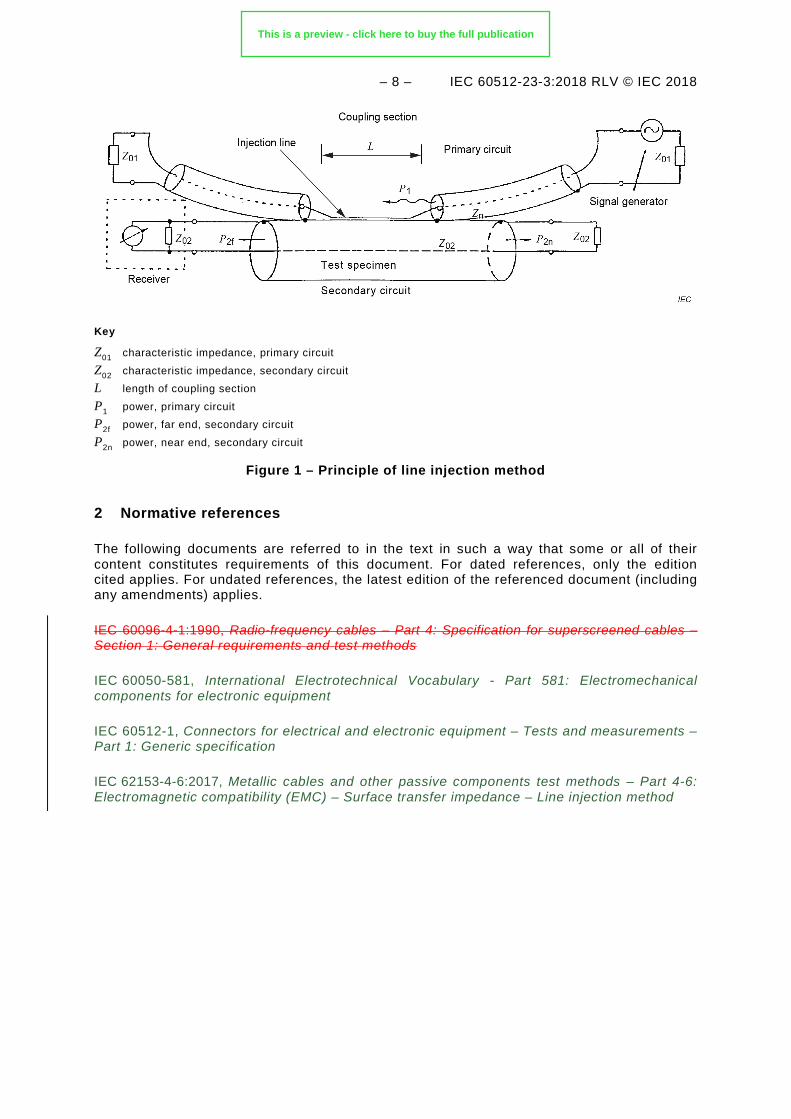
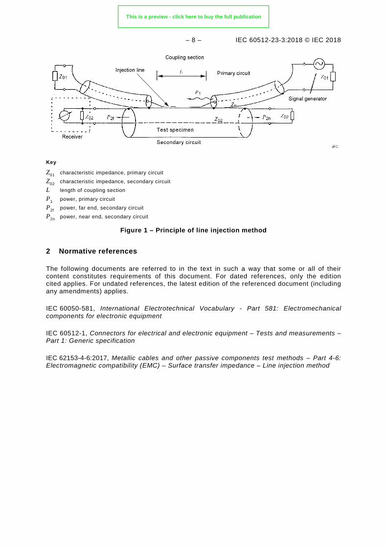
This test method is based on two impedance-matched circuits. See Figure 1 for the measurement principle. The connector specimen under test is integrated into the secondary circuit 02. The impedance-matched injection line of the primary circuit 01, which activates the electromagnetic field, runs parallel to the surface of the test sample specimen under test.
This test is also suitable for measuring the shielding effectiveness of a connector fitted with triaxial contacts terminated with shielded, twisted pair cables, as used in data bus systems.
NOTE 4 This standard has been adopted by ASD-STAN (formerly known as AECMA) as EN 2591-212 and, as such, should not be amended without direct consultation and liaison with the AECMA organization.
This is a preview - click here to buy the full publication
– 8 – IEC 60512-23-3:2018 RLV © IEC 2018
Key
Z01 characteristic impedance, primary circuit Z02 characteristic impedance, secondary circuit L length of coupling section P1 power, primary circuit P2f power, far end, secondary circuit P2n power, near end, secondary circuit
Figure 1 – Principle of line injection method
2 Normative references
The following documents are referred to in the text in such a way that some or all of their content constitutes requirements of this document. For dated references, only the edition cited applies. For undated references, the latest edition of the referenced document (including any amendments) applies.
IEC 60096-4-1:1990, Radio-frequency cables – Part 4: Specification for superscreened cables – Section 1: General requirements and test methods
IEC 60050-581, International Electrotechnical Vocabulary - Part 581: Electromechanical components for electronic equipment
IEC 60512-1, Connectors for electrical and electronic equipment – Tests and measurements – Part 1: Generic specification
IEC 62153-4-6:2017, Metallic cables and other passive components test methods – Part 4-6: Electromagnetic compatibility (EMC) – Surface transfer impedance – Line injection method
3 Terms and definitions
For the purposes of this document, the terms and definitions given in IEC 60050-581 and in IEC 60512-1 apply.
ISO and IEC maintain terminological databases for use in standardization at the following addresses:
• IEC Electropedia: available at http://www.electropedia.org/
• ISO Online browsing platform: available at http://www.iso.org/obp
This is a preview - click here to buy the full publication
IEC 60512-23-3 Edition 2.0 2018-12
INTERNATIONAL STANDARD NORME INTERNATIONALE
Connectors for electrical and electronic equipment – Tests and measurements – Part 23-3: Screening and filtering tests – Test 23c: Shielding effectiveness of connectors and accessories – Line injection method Connecteurs pour équipements électriques et électroniques – Essais et mesures – Partie 23-3: Essais d’écrantage et de filtrage – Essai 23c: Efficacité de blindage des connecteurs et des accessoires – Méthode de la ligne d’injection
IEC
605
12-2
3-3:
2018
-12
(en-
fr)
®
This is a preview - click here to buy the full publication
– 2 – IEC 60512-23-3:2018 © IEC 2018
CONTENTS
FOREWORD ........................................................................................................................... 3 INTRODUCTION ..................................................................................................................... 6 1 Scope .............................................................................................................................. 7 2 Normative references ...................................................................................................... 8 3 Terms and definitions ...................................................................................................... 8 4 Test method .................................................................................................................... 9
4.1 Test requirements ................................................................................................... 9 4.2 Applicable frequency range ..................................................................................... 9
5 Test equipment ................................................................................................................ 9 6 Preparation of the test specimen ................................................................................... 10
6.1 General ................................................................................................................. 10 6.2 Circular connectors ............................................................................................... 10 6.3 Rectangular connectors ........................................................................................ 11 6.4 Connectors for printed boards ............................................................................... 11 6.5 Impedance matching of primary and secondary circuits ......................................... 12
6.5.1 General........................................................................................................ 12 6.5.2 Preparation of the secondary circuit ............................................................. 12 6.5.3 Adaptation of the primary circuit ................................................................... 12
6.6 Calibration of test set-up ....................................................................................... 12 7 Measurement of shielding effectiveness ........................................................................ 13
7.1 Measurement ........................................................................................................ 13 7.2 Method of calculating shielding effectiveness SE (attenuation) from surface
transfer impedance ZT .......................................................................................... 13 8 Requirements ................................................................................................................ 14 9 Details to be specified ................................................................................................... 14 Bibliography .......................................................................................................................... 15 Figure 1 – Principle of line injection method ............................................................................ 8 Figure 2 – Installation of test set-up ...................................................................................... 10 Figure 3 – Example of test set-up for shielded circular connectors ........................................ 11 Figure 4 – Example of test set-up for shielded rectangular connectors .................................. 11 Figure 5 – Example of test set-up for shielded printed board connectors ............................... 12 Figure 6 – Calibration test set-up .......................................................................................... 13 Figure 7 – Example of a shielding attenuation (shielding effectiveness) plot ......................... 14
This is a preview - click here to buy the full publication
IEC 60512-23-3:2018 © IEC 2018 – 3 –
INTERNATIONAL ELECTROTECHNICAL COMMISSION
____________
CONNECTORS FOR ELECTRICAL AND ELECTRONIC
EQUIPMENT – TESTS AND MEASUREMENTS –
Part 23-3: Screening and filtering tests – Test 23c: Shielding effectiveness of connectors and accessories – Line injection method
FOREWORD
1) The International Electrotechnical Commission (IEC) is a worldwide organization for standardization comprising all national electrotechnical committees (IEC National Committees). The object of IEC is to promote international co-operation on all questions concerning standardization in the electrical and electronic fields. To this end and in addition to other activities, IEC publishes International Standards, Technical Specifications, Technical Reports, Publicly Available Specifications (PAS) and Guides (hereafter referred to as “IEC Publication(s)”). Their preparation is entrusted to technical committees; any IEC National Committee interested in the subject dealt with may participate in this preparatory work. International, governmental and non-governmental organizations liaising with the IEC also participate in this preparation. IEC collaborates closely with the International Organization for Standardization (ISO) in accordance with conditions determined by agreement between the two organizations.
2) The formal decisions or agreements of IEC on technical matters express, as nearly as possible, an international consensus of opinion on the relevant subjects since each technical committee has representation from all interested IEC National Committees.
3) IEC Publications have the form of recommendations for international use and are accepted by IEC National Committees in that sense. While all reasonable efforts are made to ensure that the technical content of IEC Publications is accurate, IEC cannot be held responsible for the way in which they are used or for any misinterpretation by any end user.
4) In order to promote international uniformity, IEC National Committees undertake to apply IEC Publications transparently to the maximum extent possible in their national and regional publications. Any divergence between any IEC Publication and the corresponding national or regional publication shall be clearly indicated in the latter.
5) IEC itself does not provide any attestation of conformity. Independent certification bodies provide conformity assessment services and, in some areas, access to IEC marks of conformity. IEC is not responsible for any services carried out by independent certification bodies.
6) All users should ensure that they have the latest edition of this publication.
7) No liability shall attach to IEC or its directors, employees, servants or agents including individual experts and members of its technical committees and IEC National Committees for any personal injury, property damage or other damage of any nature whatsoever, whether direct or indirect, or for costs (including legal fees) and expenses arising out of the publication, use of, or reliance upon, this IEC Publication or any other IEC Publications.
8) Attention is drawn to the Normative references cited in this publication. Use of the referenced publications is indispensable for the correct application of this publication.
9) Attention is drawn to the possibility that some of the elements of this IEC Publication may be the subject of patent rights. IEC shall not be held responsible for identifying any or all such patent rights.
International Standard IEC 60512-23-3 has been prepared by subcommittee 48B: Electrical connectors, of IEC technical committee 48: Electrical connectors and mechanical structures for electrical and electronic equipment.
This second edition cancels and replaces the first edition, published in 2000. This edition constitutes a technical revision.
This edition includes the following significant technical changes with respect to the previous edition:
a) an introduction has been added to provide some guidance to this document in view of concurrent test method 23g in the same family;
This is a preview - click here to buy the full publication

– 4 – IEC 60512-23-3:2018 © IEC 2018
b) the frequency range for which this test method is considered reliable moved from 1 GHz to 3 GHz, to be consistent with Figure 7 (unchanged) and current industry practice and need;
c) update to IEC 62153-4-6:2017 of former normative reference IEC 60096-4-1:1990, withdrawn and incorrect (should have been IEC 61196-1:1995, also withdrawn);
d) update to current subclause numbers of IEC 62153-4-6:2017 what were the previous subclause numbers referenced in IEC 61196-1:1995 (wrongly attributed to IEC 60096-4-1:1990). For immediate understanding the title of these subclauses has been added;
e) alignment of title to the current scope of SC 48B (connectors) and inclusion of electrical equipment as target application of said connectors (per current scope of TC 48) and explicit reference to the method – line injection – for the measurement of transfer impedance;
f) symbols SE for shielding effectiveness and ZT for surface transfer impedance added throughout the document;
g) list of connectors to which the test method is applicable – previously in 3.1 – moved in scope;
h) former name of AECMA organization changed to the current ASD-STAN; i) “specimen” used instead of “sample” throughout the document; j) clarification in the title of what transfer impedance is described in Table 3 and editorial
improvement of the same; k) “dielectric constant” changed into the updated term “relative permittivity”; l) added a note to warn about the fact that this test method requires in 6.6 a TDR with more
stringent rise time of less than 100 ps than the value of less than 350 ps specified both in IEC 62153-4-6 and in EN 50289-1-6 for the similar line injection method applied to screened cables, whereas test 23g of IEC 60512-23-7 specifies for the same purpose a TDR with a rise time of less than 200 ps;
m) adoption of term “connector housing” [IEV 581-27-10] instead of “shell” to address the connector accessory providing the shielding;
n) title “Transfer impedance ZT [Ω]” added to the ordinate axis on the left side of double log diagram of Figure 7;
o) explanatory note to clarify the conversion formula for SE from ZT added.
The text of this International Standard is based on the following documents:
FDIS Report on voting
48B/2631/CDV 48B/2670/RVC
Full information on the voting for the approval of this International Standard can be found in the report on voting indicated in the above table.
This document has been drafted in accordance with the ISO/IEC Directives, Part 2.
Future standards in this series will carry the new general title as cited above. Titles of existing standards in this series will be updated at the time of the next edition.
A list of all parts in the IEC 60512 series, published under the general title Connectors for electrical and electronic equipment – Tests and measurements, can be found on the IEC website.
The committee has decided that the contents of this document will remain unchanged until the stability date indicated on the IEC website under "http://webstore.iec.ch" in the data related to the specific document. At this date, the document will be
This is a preview - click here to buy the full publication

IEC 60512-23-3:2018 © IEC 2018 – 5 –
• reconfirmed,
• withdrawn,
• replaced by a revised edition, or
• amended.
This is a preview - click here to buy the full publication
– 6 – IEC 60512-23-3:2018 © IEC 2018
INTRODUCTION
This document is part of the IEC 60512 series within the group of standards identified as Part 23: Screening and filtering tests.
It covers a method to measure the shielding (screening) effectiveness of shielded connectors or of shielding accessories for connectors that are non-inherently shielded, e.g. connector shielded housings and/or connector EMC cable glands, by measurement of the surface transfer impedance ZT (Ω) as a function of the frequency. By using a formula, ZT is then converted in shielding effectiveness SE (dB).
In Part 23 there is another document, IEC 60512-23-7, Connectors for electronic equipment – Tests and measurements – Part 23-7 – Screening and filtering tests – Test 23g: Effective transfer impedance of connectors, that provides test 23g.
The first difference between the method described in this document and test 23g is that here in test 23c, in the measurement of the transfer impedance ZT the capacitive coupling phenomena covered by the capacity coupling impedance ZF are considered negligible, while test 23g includes these effects to measure the effective surface transfer impedance ZTE.
This test 23c is applicable to a wide range of applications: it covers circular connectors, rectangular connectors and connectors for PCBs, as well as connector shielding accessories, i.e. those accessories such as connector shielded housings and/or metal shielding plates, providing shielding properties to a non-inherently shielded connector.
Test 23g is a variant of the triaxial test method for screened cables of IEC 62153-4-7, it addresses more specifically non-circular screened (shielded) connectors, it requires as DUT a complete cable assembly, i.e. a short piece of screened cable terminated by two connectors to be tested, and it requires also two adaptors plus a specific test jig.
More differences will be clear by a comparative read of the two test methods (this test 23c and test 23g) for the choice of the most suitable test to be indicated by the connector (or accessory) product detail specification or the manufacturer specification.
For further guidance regarding EMC testing of connectors and cable assemblies with screened cables and connectors, see also IEC TS 62513-4-1.
This is a preview - click here to buy the full publication

IEC 60512-23-3:2018 © IEC 2018 – 7 –
CONNECTORS FOR ELECTRICAL AND ELECTRONIC EQUIPMENT – TESTS AND MEASUREMENTS –
Part 23-3: Screening and filtering tests – Test 23c: Shielding effectiveness
of connectors and accessories – Line injection method
1 Scope
This part of IEC 60512 defines a standard test method for measuring the shielding effectiveness SE of a shielded connector, or of a connector not provided with integral shield once fitted with a shielding accessory and terminated with a screened cable.
The complete assembly has a continuous 360° shielding capability throughout its length.
NOTE 1 Practically, continuous 360° shielding is not always achievable based on the geometry of the connector.
NOTE 2 Shielding” is used in this document with the same meaning as “screening”.
This test method can be applied to shielded connectors and to connector accessories with shielding capability. The following different connector designs can be tested:
– circular connectors; – rectangular connectors; – connectors for printed boards; – connector shielding accessories.
NOTE 3 For the definition of “accessory” see IEV 581-24-10. A shielding accessory i.e. an accessory that confers shielding to a non-inherently shielded connector, may be a suitable set of shielded housings providing electrical continuity, along the mated connector set, between the screen of the (screened) cable at the cable outlet of the free cable connector housing and the metallic mounting surface for the fixed connector housing. The free connector housing is provided with a cable screen clamp.
This test method utilizes the principle that the intrinsic shielding property of the connector/ accessory/cable assembly is its surface transfer impedance ZT which can be expressed as the longitudinal voltage inside the shield, relative to the current flow on the outside shell.
This test method is based on two impedance-matched circuits. See Figure 1 for the measurement principle. The connector specimen under test is integrated into the secondary circuit 02. The impedance-matched injection line of the primary circuit 01, which activates the electromagnetic field, runs parallel to the surface of the specimen under test.
This test is also suitable for measuring the shielding effectiveness of a connector fitted with triaxial contacts terminated with shielded, twisted pair cables, as used in data bus systems.
NOTE 4 This standard has been adopted by ASD-STAN (formerly known as AECMA) as EN 2591-212 .
This is a preview - click here to buy the full publication
– 8 – IEC 60512-23-3:2018 © IEC 2018
Key
Z01 characteristic impedance, primary circuit Z02 characteristic impedance, secondary circuit L length of coupling section P1 power, primary circuit P2f power, far end, secondary circuit P2n power, near end, secondary circuit
Figure 1 – Principle of line injection method
2 Normative references
The following documents are referred to in the text in such a way that some or all of their content constitutes requirements of this document. For dated references, only the edition cited applies. For undated references, the latest edition of the referenced document (including any amendments) applies.
IEC 60050-581, International Electrotechnical Vocabulary - Part 581: Electromechanical components for electronic equipment
IEC 60512-1, Connectors for electrical and electronic equipment – Tests and measurements – Part 1: Generic specification
IEC 62153-4-6:2017, Metallic cables and other passive components test methods – Part 4-6: Electromagnetic compatibility (EMC) – Surface transfer impedance – Line injection method
3 Terms and definitions
For the purposes of this document, the terms and definitions given in IEC 60050-581 and in IEC 60512-1 apply.
ISO and IEC maintain terminological databases for use in standardization at the following addresses:
• IEC Electropedia: available at http://www.electropedia.org/
• ISO Online browsing platform: available at http://www.iso.org/obp
This is a preview - click here to buy the full publication
– 16 – IEC 60512-23-3:2018 © IEC 2018
SOMMAIRE
AVANT-PROPOS .................................................................................................................. 17 INTRODUCTION ................................................................................................................... 20 1 Domaine d’application ................................................................................................... 21 2 Références normatives .................................................................................................. 22 3 Termes et définitions ..................................................................................................... 22 4 Méthode d’essai ............................................................................................................ 23
4.1 Exigences d’essai ................................................................................................. 23 4.2 Plage de fréquences applicable ............................................................................ 23
5 Matériel d’essai ............................................................................................................. 23 6 Préparation de l’éprouvette ............................................................................................ 24
6.1 Généralités ........................................................................................................... 24 6.2 Connecteurs circulaires ........................................................................................ 24 6.3 Connecteurs rectangulaires .................................................................................. 25 6.4 Connecteurs pour cartes de circuit imprimé .......................................................... 25 6.5 Adaptation d’impédance des circuits primaire et secondaire .................................. 26
6.5.1 Généralités .................................................................................................... 26 6.5.2 Préparation du circuit secondaire ................................................................... 26 6.5.3 Adaptation du circuit primaire ........................................................................ 26
6.6 Etalonnage du montage d’essai ............................................................................ 27 7 Mesure de l’efficacité de blindage .................................................................................. 27
7.1 Mesure ................................................................................................................. 27 7.2 Méthode de calcul de l’efficacité (l’affaiblissement) de blindage SE à partir
de l’impédance de transfert de surface ZT ............................................................ 27 8 Exigences ...................................................................................................................... 28 9 Détails à spécifier .......................................................................................................... 28 Bibliographie ......................................................................................................................... 30 Figure 1 – Principe de la méthode de la ligne d’injection ....................................................... 22 Figure 2 – Installation du montage d’essai ............................................................................ 24 Figure 3 – Exemple de montage d’essai pour connecteurs circulaires blindés ....................... 25 Figure 4 – Exemple de montage d’essai pour connecteurs rectangulaires blindés ................. 25 Figure 5 – Exemple de montage d’essai pour connecteurs blindés pour cartes de circuit imprimé ...................................................................................................................... 26 Figure 6 – Montage d’essai d’étalonnage .............................................................................. 27 Figure 7 – Exemple de tracé d’affaiblissement (d’efficacité) de blindage ............................... 28
This is a preview - click here to buy the full publication
IEC 60512-23-3:2018 © IEC 2018 – 17 –
COMMISSION ÉLECTROTECHNIQUE INTERNATIONALE
____________
CONNECTEURS POUR ÉQUIPEMENTS ÉLECTRIQUES ET
ÉLECTRONIQUES – ESSAIS ET MESURES –
Partie 23-3: Essais d’écrantage et de filtrage – Essai 23c: Efficacité de blindage des connecteurs et des accessoires –
Méthode de la ligne d’injection
AVANT-PROPOS 1) La Commission Electrotechnique Internationale (IEC) est une organisation mondiale de normalisation
composée de l'ensemble des comités électrotechniques nationaux (Comités nationaux de l’IEC). L’IEC a pour objet de favoriser la coopération internationale pour toutes les questions de normalisation dans les domaines de l'électricité et de l'électronique. A cet effet, l’IEC – entre autres activités – publie des Normes internationales, des Spécifications techniques, des Rapports techniques, des Spécifications accessibles au public (PAS) et des Guides (ci-après dénommés "Publication(s) de l’IEC"). Leur élaboration est confiée à des comités d'études, aux travaux desquels tout Comité national intéressé par le sujet traité peut participer. Les organisations internationales, gouvernementales et non gouvernementales, en liaison avec l’IEC, participent également aux travaux. L’IEC collabore étroitement avec l'Organisation Internationale de Normalisation (ISO), selon des conditions fixées par accord entre les deux organisations.
2) Les décisions ou accords officiels de l’IEC concernant les questions techniques représentent, dans la mesure du possible, un accord international sur les sujets étudiés, étant donné que les Comités nationaux de l’IEC intéressés sont représentés dans chaque comité d’études.
3) Les Publications de l’IEC se présentent sous la forme de recommandations internationales et sont agréées comme telles par les Comités nationaux de l’IEC. Tous les efforts raisonnables sont entrepris afin que l’IEC s'assure de l'exactitude du contenu technique de ses publications; l’IEC ne peut pas être tenue responsable de l'éventuelle mauvaise utilisation ou interprétation qui en est faite par un quelconque utilisateur final.
4) Dans le but d'encourager l'uniformité internationale, les Comités nationaux de l’IEC s'engagent, dans toute la mesure possible, à appliquer de façon transparente les Publications de l’IEC dans leurs publications nationales et régionales. Toutes divergences entre toutes Publications de l’IEC et toutes publications nationales ou régionales correspondantes doivent être indiquées en termes clairs dans ces dernières.
5) L’IEC elle-même ne fournit aucune attestation de conformité. Des organismes de certification indépendants fournissent des services d'évaluation de conformité et, dans certains secteurs, accèdent aux marques de conformité de l’IEC. L’IEC n'est responsable d'aucun des services effectués par les organismes de certification indépendants.
6) Tous les utilisateurs doivent s'assurer qu'ils sont en possession de la dernière édition de cette publication.
7) Aucune responsabilité ne doit être imputée à l’IEC, à ses administrateurs, employés, auxiliaires ou mandataires, y compris ses experts particuliers et les membres de ses comités d'études et des Comités nationaux de l’IEC, pour tout préjudice causé en cas de dommages corporels et matériels, ou de tout autre dommage de quelque nature que ce soit, directe ou indirecte, ou pour supporter les coûts (y compris les frais de justice) et les dépenses découlant de la publication ou de l'utilisation de cette Publication de l’IEC ou de toute autre Publication de l’IEC, ou au crédit qui lui est accordé.
8) L'attention est attirée sur les références normatives citées dans cette publication. L'utilisation de publications référencées est obligatoire pour une application correcte de la présente publication.
9) L’attention est attirée sur le fait que certains des éléments de la présente Publication de l’IEC peuvent faire l’objet de droits de brevet. L’IEC ne saurait être tenue pour responsable de ne pas avoir identifié de tels droits de brevets et de ne pas avoir signalé leur existence.
La Norme internationale IEC 60512-23-3 a été établie par le sous-comité 48B: Connecteurs électriques, du comité d'études 48 de l'IEC: Connecteurs électriques et structures mécaniques pour les équipements électriques et électroniques.
Cette deuxième édition annule et remplace la première édition, parue en 2000. Cette édition constitue une révision technique.
Cette édition inclut les modifications techniques majeures suivantes par rapport à l'édition précédente:
This is a preview - click here to buy the full publication
– 18 – IEC 60512-23-3:2018 © IEC 2018
a) ajout d’une introduction visant à donner des recommandations dans le présent document relatives à la méthode d’essai parallèle 23g, figurant dans la même famille;
b) modification de la plage de fréquences pour laquelle la présente méthode d’essai est considérée fiable, dont la limite supérieure passe de 1 GHz à 3 GHz, afin d’assurer l’homogénéité avec la Figure 7 (inchangée) et les pratiques et besoins actuels de l’industrie;
c) mise à jour de l’ancienne référence normative IEC 60096-4-1:1990, retirée et incorrecte (la référence normative à spécifier aurait dû être l’IEC 61196-1:1995, depuis elle aussi retirée), qui devient l’IEC 62153-4-6:2017;
d) mise à jour des numéros de paragraphe actuels pour refléter ceux de l’IEC 62153-4-6:2017, qui étaient auparavant les numéros de paragraphe de l’IEC 61196-1:1995 (attribués par erreur à l’IEC 60096-4-1:1990). Dans un souci de clarification, le titre de ces paragraphes a été ajouté;
e) alignement du titre sur le domaine d’application actuel du SC 48B (connecteurs) et inclusion des équipements électriques comme application cible desdits connecteurs (selon le domaine d’application actuel du TC 48), et référence explicite à la méthode (ligne d’injection) utilisée pour la mesure de l’impédance de transfert;
f) ajout dans l’ensemble du document des symboles SE pour l’efficacité de blindage, et ZT pour l’impédance de transfert de surface;
g) déplacement dans le domaine d’application de la liste des connecteurs auxquels s’applique la méthode d’essai, auparavant indiquée en 3.1;
h) modification de l’ancien nom de l’organisation AECMA pour refléter son nom actuel, l’ASD-STAN;
i) utilisation du terme «éprouvette» à la place d’«échantillon» dans l’ensemble du document; j) clarification dans le titre de l’impédance de transfert décrite dans le Tableau 3 et
amélioration éditoriale du titre; k) utilisation de l’expression actualisée «permittivité relative» à la place de l’expression
«constante diélectrique»; l) ajout d’une note de mise en garde spécifiant que cette méthode d’essai exige en 6.6 un
réflectomètre temporel avec un temps de montée inférieur à 100 ps, plus rigoureux que la valeur maximale de 350 ps spécifiée dans l’IEC 62153-4-6 et dans l’EN 50289-1-6 pour la méthode analogue de ligne d’injection appliquée aux câbles écrantés, tandis que l’essai 23g de l’IEC 60512-23-7 spécifie dans ce même contexte un RDT avec un temps de montée inférieur à 200 ps;
m) utilisation de l’expression «boîtier de connecteurs» [IEV 581-27-10] à la place du terme «capot», pour décrire l’accessoire de connecteur assurant le blindage;
n) ajout de la légende «Impédance de transfert ZT [Ω]» sur l’axe des ordonnées, en partie droite du schéma à double échelle logarithmique de la Figure 7;
o) ajout d’une note explicative visant à clarifier la formule de conversion permettant d’obtenir SE à partir de ZT.
Le texte de cette Norme internationale est issu des documents suivants:
FDIS Rapport de vote
48B/2631/CDV 48B/2670/RVC
Le rapport de vote indiqué dans le tableau ci-dessus donne toute information sur le vote ayant abouti à l'approbation de cette Norme internationale.
Ce document a été rédigé selon les Directives ISO/IEC, Partie 2.
Les futures normes de cette série porteront dorénavant le nouveau titre général cité ci-dessus. Le titre des normes existant déjà dans cette série sera mis à jour lors de leur prochaine édition.
This is a preview - click here to buy the full publication

IEC 60512-23-3:2018 © IEC 2018 – 19 –
Une liste de toutes les parties de la série IEC 60512, publiées sous le titre général Connecteurs pour équipements électriques et électroniques – Essais et mesures, peut être consultée sur le site web de l’IEC.
Le comité a décidé que le contenu de ce document ne sera pas modifié avant la date de stabilité indiquée sur le site web de l’IEC sous "http://webstore.iec.ch" dans les données relatives au document recherché. A cette date, le document sera
• reconduit,
• supprimé,
• remplacé par une édition révisée, ou
• amendé.
This is a preview - click here to buy the full publication
– 20 – IEC 60512-23-3:2018 © IEC 2018
INTRODUCTION
Le présent document fait partie de la série IEC 60512 et appartient au groupe de normes identifié par le titre secondaire Partie 23: Essais d’écrantage et de filtrage.
Il couvre une méthode de mesure de l’efficacité de blindage (d’écrantage) de connecteurs blindés, ou d’accessoires de blindage destinés à des connecteurs non intrinsèquement blindés, par exemple des boîtiers de connecteurs blindés et/ou des presse-étoupes CEM pour connecteur, en mesurant l’impédance de transfert de surface ZT (Ω) en fonction de la fréquence. En utilisant une formule, ZT est ensuite convertie en efficacité de blindage SE (dB).
La Partie 23 englobe un autre document, l’IEC 60512-23-7, Connecteurs pour équipements électroniques – Essais et mesures – Partie 23-7: Essais d’écrantage et de filtrage – Essai 23g: Impédance de transfert efficace des connecteurs, qui spécifie l’essai 23g.
La première différence entre la méthode décrite dans le présent document et l’essai 23g est que dans le présent essai 23c, pour la mesure de l’impédance de transfert ZT, les phénomènes de couplage capacitif couverts par l’impédance de couplage capacitif ZF sont considérés comme étant négligeables, tandis que l’essai 23g intègre ces effets pour mesurer l’impédance de transfert de surface effective ZTE.
Le présent essai 23c s’applique à une large gamme d’applications: il englobe les connecteurs circulaires, les connecteurs rectangulaires et les connecteurs pour cartes de circuit imprimé, ainsi que les accessoires de blindage pour connecteurs, c’est-à-dire les accessoires tels que les boîtiers de connecteurs blindés et/ou les plaques de blindage métalliques, qui fournissent des propriétés de blindage à un connecteur non intrinsèquement blindé.
L’essai 23g est une variante de la méthode d’essai triaxiale pour les câbles écrantés spécifiée dans l’IEC 62153-4-7; il porte plus spécifiquement sur des connecteurs écrantés (blindés) non circulaires, et il exige en tant que dispositif soumis à essai (DUT, Device Under Test) un câble assemblé complet, c’est-à-dire une petite longueur de câble écranté équipé à chacune de ses deux extrémités d’un connecteur à soumettre à essai, et il exige également deux adaptateurs ainsi qu’un gabarit d’essai spécifique.
Les autres différences seront plus évidentes par une lecture comparative des deux méthodes d’essai (le présent essai 23c et l’essai 23g), préalablement au choix de l’essai le plus approprié à indiquer dans la spécification particulière du connecteur (ou de l’accessoire) ou dans la spécification du fabricant.
Pour d’autres recommandations concernant les essais CEM des connecteurs et des ensembles de câble avec câbles et connecteurs écrantés, voir aussi l’IEC TS 62513-4-1.
This is a preview - click here to buy the full publication
IEC 60512-23-3:2018 © IEC 2018 – 21 –
CONNECTEURS POUR ÉQUIPEMENTS ÉLECTRIQUES ET ÉLECTRONIQUES – ESSAIS ET MESURES –
Partie 23-3: Essais d’écrantage et de filtrage – Essai 23c: Efficacité de
blindage des connecteurs et des accessoires – Méthode de la ligne d’injection
1 Domaine d’application
La présente partie de l’IEC 60512 définit une méthode d’essai normalisée pour mesurer l’efficacité de blindage SE d’un connecteur blindé, ou d’un connecteur sans blindage intégré et équipé d’un accessoire de blindage, et raccordé à un câble écranté.
Le câble assemblé présente un blindage continu sur 360° sur toute sa longueur.
NOTE 1 Le blindage continu à 360° n’est pas toujours réalisable dans la pratique, en raison de la géométrie du connecteur.
NOTE 2 Le terme «blindage» est utilisé dans le présent document comme synonyme du terme «écrantage».
La présente méthode d’essai peut être appliquée aux connecteurs blindés et aux accessoires de connecteur ayant un blindage. Les différentes conceptions de connecteur ci-après peuvent être soumises à essai:
– connecteurs circulaires, – connecteurs rectangulaires, – connecteurs pour cartes de circuit imprimé, – accessoires de blindage pour connecteur.
NOTE 3 Pour la définition du terme «accessoire», voir la référence IEV 581-24-10. Un accessoire de blindage, c’est-à-dire un accessoire qui confère un blindage à un connecteur non intrinsèquement blindé, peut être un ensemble approprié de boîtiers blindés assurant la continuité électrique, le long de l’ensemble de connecteurs accouplés, entre l’écran du câble (écranté) à la sortie du boîtier des fiches, et la surface de montage métallique pour le boîtier des embases. Le boîtier de connecteurs libre est fourni avec un serre-écran de câble.
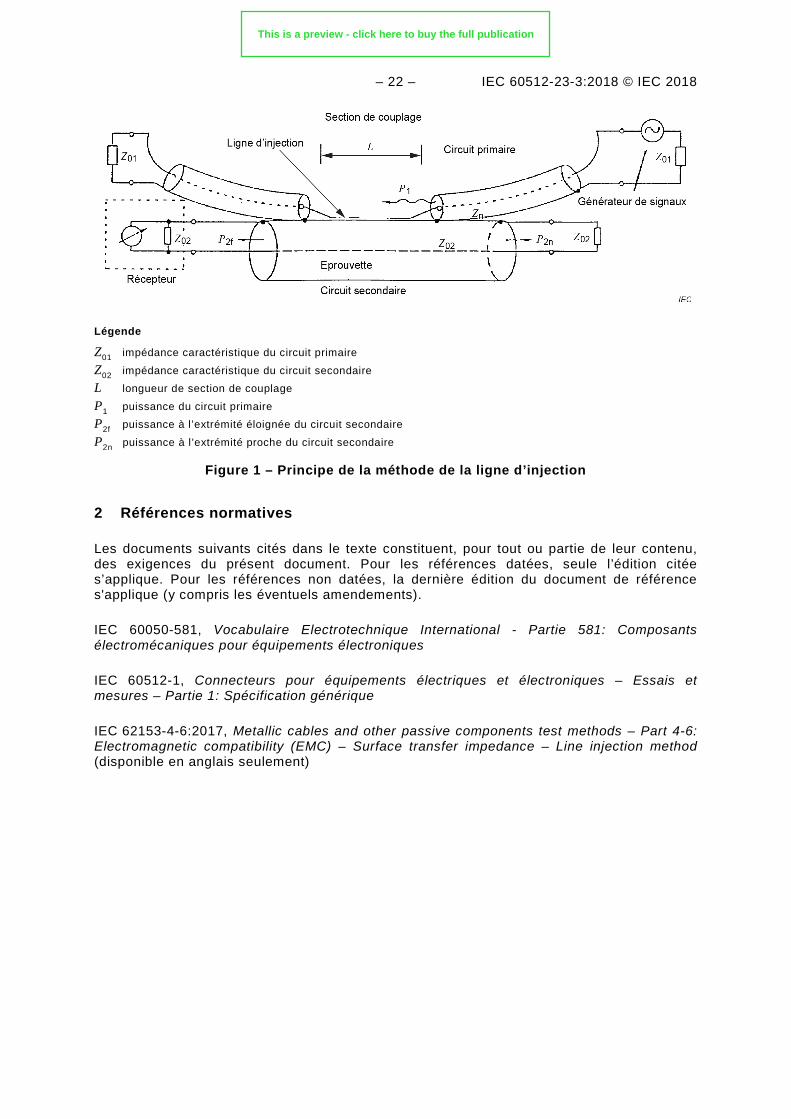
La présente méthode d’essai part du principe que la propriété intrinsèque du blindage de l’ensemble connecteur/accessoire/câble est son impédance de transfert de surface ZT, qui peut être exprimée par la tension longitudinale à l’intérieur du blindage, en fonction du courant parcourant le boîtier extérieur.
La présente méthode d’essai est basée sur deux circuits adaptés en impédance. La Figure 1 représente le principe de mesure. L’éprouvette de connecteur est intégrée au circuit secondaire 02. La ligne d’injection adaptée en impédance du circuit primaire 01, qui active le champ électromagnétique, chemine parallèlement à la surface de l’éprouvette.
Le présent essai est également adapté à la mesure de l’efficacité de blindage d’un connecteur équipé de contacts triaxiaux raccordés à des câbles blindés à paires torsadées, comme ceux utilisés dans les systèmes pour bus de données.
NOTE 4 La présente norme a été adoptée par l’ASD-STAN (anciennement l’AECMA) sous la référence EN 2591-212.
This is a preview - click here to buy the full publication
– 22 – IEC 60512-23-3:2018 © IEC 2018
Légende
Z01 impédance caractéristique du circuit primaire Z02 impédance caractéristique du circuit secondaire L longueur de section de couplage P1 puissance du circuit primaire P2f puissance à l’extrémité éloignée du circuit secondaire P2n puissance à l’extrémité proche du circuit secondaire
Figure 1 – Principe de la méthode de la ligne d’injection
2 Références normatives
Les documents suivants cités dans le texte constituent, pour tout ou partie de leur contenu, des exigences du présent document. Pour les références datées, seule l’édition citée s’applique. Pour les références non datées, la dernière édition du document de référence s'applique (y compris les éventuels amendements).
IEC 60050-581, Vocabulaire Electrotechnique International - Partie 581: Composants électromécaniques pour équipements électroniques
IEC 60512-1, Connecteurs pour équipements électriques et électroniques – Essais et mesures – Partie 1: Spécification générique
IEC 62153-4-6:2017, Metallic cables and other passive components test methods – Part 4-6: Electromagnetic compatibility (EMC) – Surface transfer impedance – Line injection method (disponible en anglais seulement)
3 Termes et définitions
Pour les besoins du présent document, les termes et définitions de l’IEC 60050-581 et de l’IEC 60512-1 s’appliquent.
L’ISO et l’IEC tiennent à jour des bases de données terminologiques destinées à être utilisées en normalisation, consultables aux adresses suivantes:
• IEC Electropedia: disponible à l’adresse http://www.electropedia.org/
• ISO Online browsing platform: disponible à l’adresse http://www.iso.org/obp
This is a preview - click here to buy the full publication


![04_Mine SHP RLV Presentation [Compatibility Mode]](https://img.pdfslide.us/doc/110x75/577cddbe1a28ab9e78ada2a8/04mine-shp-rlv-presentation-compatibility-mode.jpg)
