Embed Size (px)
Citation preview

Inst
alla
tio
n a
nd
Op
erat
ion
Man
ual
- Z
BM
2
Redflow Installation and Operation Manual
ZBM2 (3kW/10kWh) ORIGINAL INSTRUCTIONS
V2.9

Page 2 Redflow Installation and Operation Manual – ZBM2 Document ID: IMRFS22 | Version: 2.9 2018 | Redflow Limited | All Rights Reserved
Thank you for purchasing the Redflow ZBM2.
Redflow’s ZBM2 represents the state-of-the-art in zinc-bromine flow battery technology.
It is designed as a modular battery to be integrated into electricity storage systems.
For Sales and Technical Support, Redflow can be contacted at:
Redflow Limited
ABN 49 130 227 271
27 Counihan Road
Seventeen Mile Rocks
Brisbane
QLD 4073
Australia
W: www.redflow.com
T: +61 7 3376 0008
F: +61 7 3376 3751
Office hours: 8:30am to 5:00pm, Brisbane, Australia
Monday - Friday
© 2018. Redflow Limited. All Rights Reserved.
Any reproduction, modification, or electronic transmission of this publication requires the prior
written authorisation of Redflow Limited.

Page 3 Redflow Installation and Operation Manual – ZBM2 Document ID: IMRFS22 | Version: 2.9 2018 | Redflow Limited | All Rights Reserved
Table of Contents
1. Introduction .................................................................................................................................... 8
1.1. About the ZBM2 ...................................................................................................................... 8
2. ZBM2 Safety .................................................................................................................................. 11
2.1. Electrolyte Characteristics .................................................................................................... 11
2.1.1. Bromide and Bromine Complex .................................................................................... 12
2.1.2. Gas Emissions ................................................................................................................ 13
2.1.3. Electrolyte Leaks ........................................................................................................... 13
2.1.4. Personal Protective Equipment (PPE) ........................................................................... 13
2.2. ZBM2 Battery Voltage Hazard ............................................................................................... 14
2.3. ZBM2 Fire Safety Characteristics .......................................................................................... 14
2.4. ZBM2 Safety Labels ............................................................................................................... 14
2.4.1. ZBM2 Label .................................................................................................................... 14
2.4.2. Hazard Label .................................................................................................................. 15
3. ZBM2 Handling .............................................................................................................................. 16
3.1. ZBM2 Weights & Dimensions ............................................................................................... 16
3.2. Lifting Straps ......................................................................................................................... 16
3.3. ZBM2 Crate Removal Process ............................................................................................... 16
3.4. Dry ZBMs ............................................................................................................................... 18
3.5. Transporting ZBM2s .............................................................................................................. 18
3.6. Storing ZBM2s ....................................................................................................................... 19
4. ZBM2 Components ....................................................................................................................... 20
4.1. Electrode Stack ...................................................................................................................... 22
4.2. Electrolyte Tanks ................................................................................................................... 23
4.3. Pumps ................................................................................................................................... 23
4.4. Catch Can .............................................................................................................................. 23
4.5. Cooling Tubes ........................................................................................................................ 24
4.6. Fan ......................................................................................................................................... 24
4.7. Gas Handling Units ................................................................................................................ 24
4.8. Lifting Straps ......................................................................................................................... 25
4.9. Sensor Analog Loom ............................................................................................................. 25

Page 4 Redflow Installation and Operation Manual – ZBM2 Document ID: IMRFS22 | Version: 2.9 2018 | Redflow Limited | All Rights Reserved
4.9.1. Tank Leak Sensor ........................................................................................................... 25
4.9.2. Floor Leak Sensor .......................................................................................................... 26
4.10. Power Cables ..................................................................................................................... 26
4.11. MMS .................................................................................................................................. 26
4.12. BMS ................................................................................................................................... 27
4.13. Safety Guards and Covers ................................................................................................. 28
4.13.1. Terminal Collar .............................................................................................................. 28
4.13.2. MMS Box Cover ............................................................................................................. 29
4.13.3. Pump Cover ................................................................................................................... 29
4.13.4. Fan Cover ...................................................................................................................... 30
5. ZBM2 Installation and Connection................................................................................................ 31
5.1. ZBM Set-Up Example: Inverter and Load .............................................................................. 38
6. ZBM2 Operation ............................................................................................................................ 40
6.1. Operating “From Empty” ...................................................................................................... 40
6.2. ZBM2 Operating Modes ........................................................................................................ 40
6.3. Discharge Curves ................................................................................................................... 40
6.4. Start Up Procedure ............................................................................................................... 41
6.5. Shutdown Procedure ............................................................................................................ 43
7. ZBM2 Wear and Failure Processes ............................................................................................... 45
7.1. Leaks...................................................................................................................................... 45
7.2. Stack Degradation ................................................................................................................. 45
7.3. Incorrect Operation .............................................................................................................. 45
7.4. Electrolyte Contamination .................................................................................................... 45
7.5. Pump Failures ........................................................................................................................ 45
7.6. Electronics and Electrical ...................................................................................................... 46
7.7. Over Temperature ................................................................................................................ 46
8. ZBM2 Maintenance ....................................................................................................................... 47
8.1. Ongoing Maintenance ........................................................................................................... 47
8.2. Periodic Maintenance ........................................................................................................... 48
8.3. Cleaning ................................................................................................................................. 49
9. ZBM2 System Integration ............................................................................................................. 50
9.1. System Design Guidelines – Safety ....................................................................................... 50
9.1.1. Shutdown Systems ........................................................................................................ 50
9.1.2. Spillage Management System ....................................................................................... 50

Page 5 Redflow Installation and Operation Manual – ZBM2 Document ID: IMRFS22 | Version: 2.9 2018 | Redflow Limited | All Rights Reserved
9.1.3. Hydrogen & Bromine Gas Management/Detection System ......................................... 50
9.1.4. Fire Control System ....................................................................................................... 51
9.1.5. Noise ............................................................................................................................. 51
9.2. System Design Guidelines – Mechanical ............................................................................... 51
9.2.1. Separation of ZBM2s and ESS Electronics ..................................................................... 52
9.2.2. Corrosion Protection ..................................................................................................... 52
9.2.3. Ventilation Requirements ............................................................................................. 53
9.2.4. Securing ZBM2s ............................................................................................................. 53
9.3. System Design Guidelines – Thermal Management ............................................................. 53
9.3.1. Temperature Considerations ........................................................................................ 54
9.4. System Design Guidelines – Electrical ................................................................................... 54
9.4.1. Voltages ......................................................................................................................... 55
9.4.2. Currents ......................................................................................................................... 55
9.4.3. Power Output ................................................................................................................ 56
9.4.4. Energy Output ............................................................................................................... 56
9.4.5. Response Time .............................................................................................................. 56
9.4.6. Efficiency ....................................................................................................................... 56
9.4.7. Self-Maintenance .......................................................................................................... 56
9.4.8. Parallel Arrangements of ZBM2s .................................................................................. 57
9.5. System Design Guidelines – Communications ...................................................................... 58
Abbreviations and Definitions ...................................................................................... 59 Appendix A
EC Declaration of Conformity ....................................................................................... 60 Appendix B
Addressing ZBM2 Electrolyte Spills/Leaks .................................................................... 61 Appendix C
Maintenance Checklist .................................................................................................. 64 Appendix D
Standard Cycle .............................................................................................................. 65 Appendix E
Redflow ZBM2 Safety Data Sheet.............................................................................. 66 Appendix F
Document Revision History ........................................................................................... 83 Appendix G

Page 6 Redflow Installation and Operation Manual – ZBM2 Document ID: IMRFS22 | Version: 2.9 2018 | Redflow Limited | All Rights Reserved
List of Figures Figure 1: Electrolyte phase and bromine complex phase ..................................................................... 12
Figure 2: Vapour pressures for charged bromine complex, battery electrolyte and pure bromine .... 12
Figure 3: ZBM2 label ............................................................................................................................. 15
Figure 4: Hazard label ........................................................................................................................... 15
Figure 5: Crate bolt points .................................................................................................................... 17
Figure 6: Lifting crate lid ....................................................................................................................... 17
Figure 7: Plastic bag and foam .............................................................................................................. 17
Figure 8: Lifting Strap location .............................................................................................................. 18
Figure 9: ZBM2 components (front and side view)............................................................................... 20
Figure 10: ZBM2 components (back and side view) ............................................................................. 21
Figure 11: ZBM2 terminal plates and pumps (front side view) ............................................................ 22
Figure 12: ZBM2 pumps ........................................................................................................................ 23
Figure 13: Catch can .............................................................................................................................. 24
Figure 14: Gas handling units ................................................................................................................ 24
Figure 15: Sensor analog loom .............................................................................................................. 25
Figure 16: MMS connections ................................................................................................................ 27
Figure 17: MMS terminal connections .................................................................................................. 27
Figure 18: Redflow BMS ........................................................................................................................ 28
Figure 19: Terminal collar ..................................................................................................................... 29
Figure 20: Fan cover .............................................................................................................................. 30
Figure 21: Hoses and hose clamps on the ZBM2 .................................................................................. 31
Figure 22: Positive and negative ZBM2 terminals ................................................................................ 32
Figure 23: ZBM2 terminal connections ................................................................................................. 32
Figure 24: Catch Can masking tape removal ......................................................................................... 33
Figure 25: Viton tube ............................................................................................................................ 33
Figure 26: Lifting the ZBM2 ................................................................................................................... 34
Figure 27: Tank Leak Sensor location .................................................................................................... 34
Figure 28: Battery Temperature Sensor location.................................................................................. 34
Figure 29: Ambient Temperature Sensor location................................................................................ 34
Figure 30: MMS connections ................................................................................................................ 34
Figure 31: BMS connections ................................................................................................................. 35
Figure 32: Cat6 cable assembly ............................................................................................................. 36
Figure 33: MMS communication cable connected ............................................................................... 36
Figure 34: MMS Connections ................................................................................................................ 37
Figure 35: Bus cable connections .......................................................................................................... 37
Figure 36: Belleville washer orientation (side view) ............................................................................. 37
Figure 37: Torque marking .................................................................................................................... 38
Figure 38: Lifting straps ......................................................................................................................... 38
Figure 39: Example connections for testing the ZBM2 ......................................................................... 38
Figure 40: ZBM2 performance at different C rates ............................................................................... 41
Figure 41: BMS interface showing Battery Setup selection .................................................................. 41
Figure 42: BMS interface showing Battery Setup screen ...................................................................... 42

Page 7 Redflow Installation and Operation Manual – ZBM2 Document ID: IMRFS22 | Version: 2.9 2018 | Redflow Limited | All Rights Reserved
Figure 43: BMS interface showing Upgrade Battery selection ............................................................. 42
Figure 44: BMS interface showing Battery Firmware Upgrade screen ................................................. 42
Figure 45: BMS interface showing how to bring a ZBM2 online .......................................................... 43
Figure 46: BMS interface showing how to take a ZBM2 offline ........................................................... 43
Figure 47: BMS interface showing warning and failure alarms on the Status page ............................. 47
Figure 48: BMS interface showing details warnings and failures on the Battery Status page ............. 48
Figure 49: Excerpt from Figure 50 showing ZBM2 voltage profile ....................................................... 55
Figure 50: An example of the Redflow ZBM2’s Standard Cycle ............................................................ 65
List of Tables Table 1: ZBM2 Electrical Operating Envelope ......................................................................................... 9
Table 2: ZBM2 Physical and Communications Characteristics.............................................................. 10

Page 8 Redflow Installation and Operation Manual – ZBM2 Document ID: IMRFS22 | Version: 2.9 2018 | Redflow Limited | All Rights Reserved
1. Introduction This manual is used for Redflow’s DC flowing electrolyte battery product, the Zinc-Bromine Module 2
(ZBM2). It provides information on this battery’s installation, operation and maintenance for
nominal 48VDC systems. Installation of the ZBM2 is to be done by trained installers.
1.1. About the ZBM2 Redflow’s ZBM2 is a fully DC modular flow battery with in-built intelligence. With appropriate
ancillary circuitry, multiple ZBM2s can be connected together in parallel.
The ZBM2 is ideally suited to deep cycling and long cycle life energy storage applications requiring
multiple hours of discharge on a daily basis. It can operate to 100% discharge or partial depths of
discharge without a reduction in operating life.
ZBM2 main components:
Tanks (including electrolyte)
Electrode Stacks
Module Management System (MMS)
Analog Loom
Pumps (Zinc and Bromine)
Cooling Fan
Cooling Tubes
Gas Handling Units
Battery operation is controlled and managed by the internals of the MMS. Operation of ZBM2s must
be kept within the boundaries of the operating envelope set out in Table 1 to ensure correct
operation and also to comply with warranty conditions. It should be noted that in applications where
one ZBM2 would not be able to remain within the operating envelope, adding another ZBM2 may
bring the performance of each ZBM2 back within the envelope.

Page 9 Redflow Installation and Operation Manual – ZBM2 Document ID: IMRFS22 | Version: 2.9 2018 | Redflow Limited | All Rights Reserved
Table 1: ZBM2 Electrical Operating Envelope
Power Range 0kW to 2.5kW during charge
0kW to 3kW continuous during discharge (5kW peak for up to 40 minutes)
Note: Refer to Section 9.4.3 for more information about peak power.
Net Energy Range 0kWh (0% SOC) to 10kWh (100% SOC)
DC Voltage Operating Range 36 to 58V DC
Absolute Voltage Range 32 to 70V DC
Note: ZBM2 terminal voltage = 0V on initial start-up & after maintenance cycles
Quiescent Current Draw 1.5A DC maximum @ 40V DC
Auxiliary Power 180W maximum @ 32V DC minimum
Circuit Protection Maximum rating of 125A
Operating Battery Temperature Range 10 to 50 °C (50 to 122 °F) Charging
15 to 50 °C (59 to 122 °F) Discharging
Ambient Temperature Range Operation: 5 to 50 °C (41 to 122 °F) | Storage: -10 to 50 °C (14 to 122 °F)
Self-Maintenance Cycle Frequency Typically at least once every 72 hours of zinc pump operation.
Users must not override ZBM2 internal automatic self-maintenance procedures.
Net Energy Efficiency 80% DC-DC maximum
Minimum Energy Efficiency Performance Requirement 68.0% gross (energy out/energy in) for Standard Cycle described in Appendix E.
EMC Compliance Emissions: EN61000-6-3:2007; Immunity: EN61000-4-2, 3, 4, 5, 6:2007
Approvals
CE (A copy of the EC Declaration of Conformity is available on Redflow’s website and is attached in Appendix B.)
RCM
It should be noted that any voltage exceeding the absolute maximum voltage specified in Table 1 will
damage the electronics in the MMS if connected to the ZBM2.
The physical and communications characteristics of the ZBM2 can be found in Table 2.
Page 10 Redflow Installation and Operation Manual – ZBM2 Document ID: IMRFS22 | Version: 2.9 2018 | Redflow Limited | All Rights Reserved
Table 2: ZBM2 Physical and Communications Characteristics
Dimensions (ZBM2) 830 L x 823 H x 400 W (mm)
32.7 L x 32.4 H x 15.7 W (in)
Weight (ZBM2) 240 kg (529.1 lb) ZBM2 with electrolyte
90 kg (198.4 lb) ZBM2 without electrolyte
Dimensions (crated) 1080 L x 1040 H x 660 W (mm)
42.6 L x 41.0 H x 26.0 W (in)
Weight (crated) 320 kg (705.4 lb) Redflow crated ZBM2 with electrolyte
170 kg (374.8 lb) Redflow crated ZBM2 with electrolyte
Stability (Maximum Tilt Angles)
(see Figure 9 for orientations)
Sideways (left/right): 25°
Lengthways (front/back): 45°
Diagonally: 45°
Electrolyte Volume 100 L (26 US Gal)
Module Geometry Two parallel stacks of 30 cells
Dangerous Goods Class DG Class 8 for electrolyte or ZBM2s containing any trace of electrolyte
Orientation The ZBM2 must be kept in an upright position (orientation shown in Figure 9) at all times of operation, storage, handling and transportation
Weather Protection The ZBM2 must be installed indoors (out of weather) or in a weather-proof enclosure
Operating Conditions Stationery applications on flat, level, fully-supported base surfaces only
Ventilation The ZBM2 must be adequately ventilated with minimum airflow of 50L/s (180 m
3/h)
per ZBM2 not opposing the direction of ZBM2 cooling fan airflow
Humidity Conditions 5%-95% humidity, non-condensing
Explosive Environments The ZBM2 is not intended for use in explosive environments
ZBM2 Bus Terminal Connection Positive: 8mm (approx. 5/16 inch) eyelet
Negative: 8mm (approx. 5/16 inch) eyelet
ZBM2 Bus Terminal Torque 10 Nm (7.4 ft-lb) (applies to fasteners fitted to MMS studs)
Communications RS-485 MODBUS RTU

Page 11 Redflow Installation and Operation Manual – ZBM2 Document ID: IMRFS22 | Version: 2.9 2018 | Redflow Limited | All Rights Reserved
2. ZBM2 Safety
The following general safety rules apply for any operation of the ZBM2 batteries.
Use tools with suitably rate insulated handles to make connections.
No smoking near ZBMs.
Check that cable connections between the ZBM2 and the rest of the Energy Storage System
are tightened to the recommended torque value in Table 2, and torqued nuts and MMS are
marked.
Check DC cabling polarity to the ZBM2 is correct prior to powering the system up.
Even when disconnected, a ZBM2 battery can remain charged and have voltage on the
battery terminals.
There are also four main areas of safety specifically relevant to the ZBM2 battery.
Electrolyte characteristics
ZBM2 battery voltage
ZBM2 fire safety characteristics
ZBM2 safety labelling
These are explained in detail in the sections below.
2.1. Electrolyte Characteristics
The Redflow ZBM2 is a flowing electrolyte battery containing approximately 100L (26gal) of water-
based zinc-bromide electrolyte.
The ZBM2 electrolyte is an aqueous (water-based) solution of zinc-bromide salt including additional
supporting salts and complexing agents.
The electrochemical process of charging a ZBM2 battery alters the electrolyte. Zinc ions are plated
out as metallic zinc, and bromide ions become linked with the complexing agents in the electrolyte
to form a separate dense Bromine Complex phase.
Electrolyte is yellow to orange in colour, while the Bromine Complex phase is dark red (see Figure 1).
This complex phase has a higher density and readily separates (sinks) from the aqueous electrolyte
phase and can be described as “oil-like”.
All low voltage (LV) wiring must be performed by licensed electrical personnel who are responsible for ensuring that all local and government regulations and standards are complied with.
Ensure local government regulations and standards are complied with
when working with ZBM2 electrolyte.

Page 12 Redflow Installation and Operation Manual – ZBM2 Document ID: IMRFS22 | Version: 2.9 2018 | Redflow Limited | All Rights Reserved
Figure 1: Electrolyte phase and bromine complex phase
The Safety Datasheet (SDS) is included in Appendix F of this manual.
2.1.1. Bromide and Bromine Complex ZBM2 electrolyte contains Bromine ions, which are complexed with a quaternary ammonium salt (N-
ethyl-N-methylpyrrolidiniumbromide, or MEP) to form the separate dense bromine complex phase,
as the battery is charged.
MEP maintains the concentration of elemental Bromine in the aqueous electrolyte at very low levels,
of approximately 0.04 mol/L. MEP also reduces the vapour pressure of Bromine above the liquid to
levels well below that of pure bromine.
Figure 2 shows the significantly lower vapour pressures of bromine complex (with 1500g/l of
Bromine) and charged aqueous electrolyte (with 15g/l of Bromine), compared to pure Bromine.
Figure 2: Vapour pressures for charged bromine complex, battery electrolyte and pure bromine
Studies of both small and large leaks of Bromine complex have shown that the concentration of
Bromine evaporation in the air is well below the safe long-term working level of 0.1 ppm (as
specified by the Occupational Safety and Health Administration and National Institute of
Occupational Safety and Health in the United States). In this complexed form, Bromine is:
Personnel responsible for handling the ZBM2’s electrolyte, including when cleaning up an electrolyte spill, must be aware of the content of these Safety Datasheets and the following safety information.
Dark red complex
Yellow electrolyte

Page 13 Redflow Installation and Operation Manual – ZBM2 Document ID: IMRFS22 | Version: 2.9 2018 | Redflow Limited | All Rights Reserved
Easy to detect early via its chlorine-like smell
Easy to neutralize (e.g. with sodium bicarbonate or ammonia)
Poses no fire risk (Bromine is actually used in many fire retardants)
Despite the fact that there is a very low risk of being exposed to unsafe Bromine gas levels, all
personnel involved in opening a ZBM2 to fill it with electrolyte, clean up an electrolyte spill, or
empty electrolyte from a ZBM2, must wear the appropriate Personal Protective Equipment (PPE)
(refer to Section 2.1.4).
Bromine has a chlorine-like smell and if this is detected, operation of the ZBM2 should be ceased
and the user should investigate whether there are any electrolyte leaks.
2.1.2. Gas Emissions Low levels of gas may be emitted during operation of the ZBM2 via the ZBM2’s low pressure relief
valve. This gas is automatically diverted to the ZBM2’s Catch Can, which traps gases using activated
carbon, reducing the concentration of any emissions that exit the ZBM2. Regardless, energy storage
systems containing ZBM2s shall be located in areas designed to ensure adequate ventilation. Refer
to Section 9.2.3 for more information about ventilation requirements. Standards such as AS4086.2
(Section 2.7) also provide guidelines about battery room ventilation.
2.1.3. Electrolyte Leaks The presence of liquid electrolyte in the ZBM2 means that there is potential for a spill to occur. Any
electrolyte leak or spill shall be cleaned up in accordance with Appendix C.
It should be noted that the ZBM2’s own electrolyte tanks are able to store a small amount of
electrolyte in the case of a minor leak. However, to prevent electrolyte spillage during major leaks,
readily available polyethylene-lined containers or bunding should also be used to contain any spilled
electrolyte. This is the same material that the electrolyte tanks are made of.
2.1.4. Personal Protective Equipment (PPE) The following, or equivalent, PPE must be worn when handling electrolyte or cleaning up an
electrolyte leak.
Respirator: Moldex half-face pre-assembled respirator with multi-gas/vapour cartridges
(available from Protector Alsafe (www.protectoralsafe.com.au), product
code 8602A, part number 0109 0268)
Goggles: Bollé Blast Duo goggles (available from Protector Alsafe, product code
1669211, part number 0708 2904)
Gloves: Prosafe Premium 806 Blue PVC Gauntlets (available from Protector Alsafe,
part number 0784 1563)
Spills and leaks of ZBM2 electrolyte shall be cleaned up immediately, where possible.

Page 14 Redflow Installation and Operation Manual – ZBM2 Document ID: IMRFS22 | Version: 2.9 2018 | Redflow Limited | All Rights Reserved
Spill kits should be kept on hand at all times, e.g. 62 litre Hazchem spill kits can be sourced from
Global Spill Control at: http://www.globalspill.com.au/?gclid=CMTvvobp-64CFYJLpgodSBzjwQ.
It should be noted that there is approximately 100L of electrolyte in each ZBM2, and while any leak
would be unlikely to result in more than a few millilitres of electrolyte escaping, there is potential for
a leak of up to 100L to occur.
Redflow’s contracted global emergency contact can also provide additional details on how to clean
up an electrolyte leak. Contact details are provided in the SDS in Appendix F.
2.2. ZBM2 Battery Voltage Hazard A single ZBM2 can have between 0V and 58V DC on the battery terminals during operation. The
voltage across the battery terminals will be 0V when it is fully discharged and it is not connected to
any other power source. See Figure 11 to identify the battery terminals. While the ZBM2 should be
fully discharged (terminal voltage at 0V) during transportation or storage, care shall be taken in case
the terminals are live.
In addition, there are internal voltages in the ZBM2 of 141V that can reach up to approximately
160V. As a result, all safety guards and covers (see Section 4.13) shall always be kept secured on the
ZBM2 unless it has been de-energised and these guards need to be removed for maintenance
purposes.
2.3. ZBM2 Fire Safety Characteristics The ZBM2 is an inherently low fire risk battery as its electrolyte is non-flammable and has many
characteristics of a fire retardant (see Section 5 in the SDS in Appendix F).
As a failsafe measure, the ZBM2 automatically shuts its electrolyte pumps off if it detects a leak. This
prevents further electrolyte from being introduced into the battery’s stack. This means that the
battery cannot self-sustain an energy discharge. While there will be a slight increase in temperature,
these measures prevent a thermal-runaway situation from occurring.
2.4. ZBM2 Safety Labels
2.4.1. ZBM2 Label The ZBM2 label is located on top of the electrode stack, near the ZBM2 terminals. Figure 3 shows
the ZBM2 label and the information it conveys.

Page 15 Redflow Installation and Operation Manual – ZBM2 Document ID: IMRFS22 | Version: 2.9 2018 | Redflow Limited | All Rights Reserved
Figure 3: ZBM2 label
2.4.2. Hazard Label The electrical hazard label shown in Figure 4 is located on:
the top of the MMS box
the top of the Zinc Pump Cover
the top of the Bromine Pump Cover
on top of the Terminal Collar
Figure 4: Hazard label

Page 16 Redflow Installation and Operation Manual – ZBM2 Document ID: IMRFS22 | Version: 2.9 2018 | Redflow Limited | All Rights Reserved
3. ZBM2 Handling
3.1. ZBM2 Weights & Dimensions
Dimensions (ZBM2) 830 L x 823 H x 400 W (mm)
32.7 L x 32.4 H x 15.7 W (in)
Weight (ZBM2) 240 kg (529.1 lb) ZBM2 with electrolyte
90 kg (198.4 lb) ZBM2 without electrolyte
Dimensions (crated) 1080 L x 1040 H x 660 W (mm)
42.6 L x 41.0 H x 26.0 W (in)
Weight (crated) 320 kg (705.4 lb) Redflow crated ZBM2 with electrolyte
170 kg (374.8 lb) Redflow crated ZBM2 with electrolyte
The ZBM2 is delivered from Redflow in a wooden crate. The crate can be moved using an
appropriately rated forklift or pallet jack.
3.2. Lifting Straps The ZBM2 is supplied with two lifting straps to enable safe handling of a ZBM2 when not in an
enclosure. The straps are rated to handle lifting of a ZBM2 filled with electrolyte and shall be used to
move a ZBM2 in an upright orientation using only a suitably rated lifting device for the ZBM2’s
weight.
Lifting requirements:
Lifting of the ZBM2 shall not be done manually.
Any handling of the ZBM2 shall involve the use of the 2 lifting straps supplied with the
ZBM2 with two personnel on hand.
Lifting straps shall not be removed from the ZBM2 when installed as they will be required
for use in removal of the ZBM2.
3.3. ZBM2 Crate Removal Process
The ZBM2 shall always be operated, handled, stored and transported in the upright position.
Transportation and lifting devices shall be appropriately rated.
The ZBM2 shall always be discharged before transportation
The ZBM2 shall never be lifted or manhandled via the battery stack. Always lift and manhandle the ZBM2 from the bottom tank.
Green strapping that loops around stack and tank is not to be removed.

Page 17 Redflow Installation and Operation Manual – ZBM2 Document ID: IMRFS22 | Version: 2.9 2018 | Redflow Limited | All Rights Reserved
The ZBM2 is to be removed from its crate using the following procedure:
1. Confirm that the lifting devices can handle the weight of the ZBM2 and a crated ZBM2.
2. Remove the 4 bolts at the base of the box using a 15mm (9/16”) socket.
Figure 5: Crate bolt points
3. Remove the crate lid with one person lifting at each end.
Figure 6: Lifting crate lid
4. Undo the plastic bag and remove the foam.
Figure 7: Plastic bag and foam

Page 18 Redflow Installation and Operation Manual – ZBM2 Document ID: IMRFS22 | Version: 2.9 2018 | Redflow Limited | All Rights Reserved
5. Ensure the two straps are positioned around the sides of an upright ZBM2 (not front to
back) approximately 1/3 and 2/3 along the ZBM2’s long side. The parts of the straps that go
under the ZBM2 must be located in the recessed section of the ZBM2 to prevent slippage.
Figure 8: Lifting Strap location
6. Continue with the instructions given in Section 5 to install and connect the ZBM2.
3.4. Dry ZBMs The ZBM2 will in most cases be delivered filled with electrolyte (wet), but in some cases (via air
freight), the ZBM2 will be delivered without electrolyte. When delivered dry, the electrolyte will be
delivered in separate transport containers. This requires the ZBM2 to be filled with electrolyte prior
to use. Please contact Redflow or the appropriate Systems Integrator for an additional guide for this
procedure.
3.5. Transporting ZBM2s
When transporting a ZBM2, the following is required:
ZBM2 must be transported in an upright position on a flat, fully-supported base surface.
If not using the original crating, construct a crate to handle the weight of the ZBM2 and
securely hold down the ZBM2.
Transport of ZBM2s must also conform to local and/or international regulations.
Where possible, transport ZBM2s in an area that has secondary containment, for example,
a catchment tray or bunding.
A ZBM2 filled with electrolyte, as well as a ZBM2 that once contained electrolyte, must be handled, stored and transported as an item with a Dangerous Goods Classification of 8, see Appendix F for the Safety Datasheet. ZBM2s that have never contained electrolyte do not require a Dangerous Goods rating or similar considerations during handling.

Page 19 Redflow Installation and Operation Manual – ZBM2 Document ID: IMRFS22 | Version: 2.9 2018 | Redflow Limited | All Rights Reserved
3.6. Storing ZBM2s ZBM2s can generally be stored indefinitely in their wet state, but must always be fully discharged.
Wet ZBM2s are classified as Dangerous Goods Class 8.
In all cases, ZBM2s shall be stored on a flat, stable and fully-supported base surface in an upright
position. The storage area shall be dry and ventilated; closed cycle air-conditioned spaces are not
suitable. ZBM2s shall be stored in areas that do not receive direct sunlight, as ultraviolet rays can
breakdown the ZBM2’s polyethylene components.
The ambient temperature should adhere to the operating temperature range specified in Table 1.
It is recommended that secondary containment, such as a catchment tray or bunding (not provided
with the ZBM2) is used to reduce the spread of electrolyte in the event of an accidental leak or spill.

Page 20 Redflow Installation and Operation Manual – ZBM2 Document ID: IMRFS22 | Version: 2.9 2018 | Redflow Limited | All Rights Reserved
4. ZBM2 Components See Figure 9, Figure 10 and Figure 11 for the components of the ZBM2.
Figure 9: ZBM2 components (front and side view)
Bromine Pump
Zinc Electrolyte Tank
823 mm
(32.4 in)
830 mm (32.7 in)
400 mm (15.7 in)
Bromine
Electrolyte
Tank
MMS
Cooling tubes
2 Electrode
Stacks
Page 21 Redflow Installation and Operation Manual – ZBM2 Document ID: IMRFS22 | Version: 2.9 2018 | Redflow Limited | All Rights Reserved
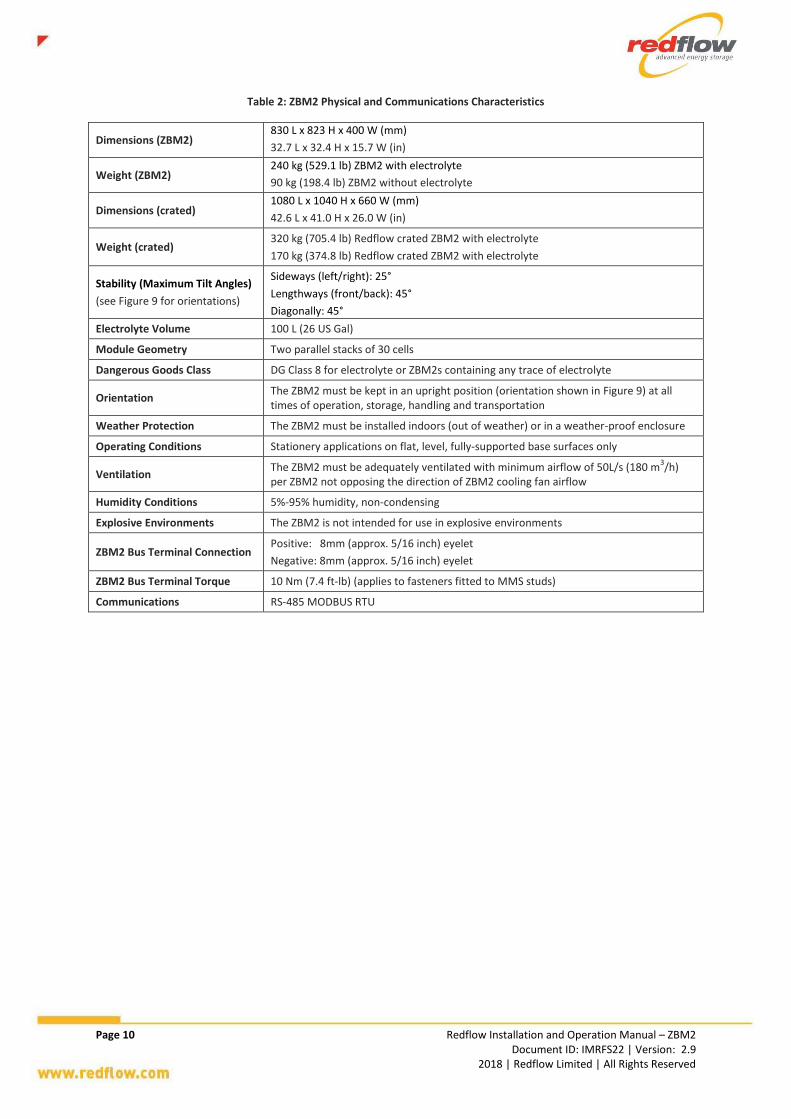
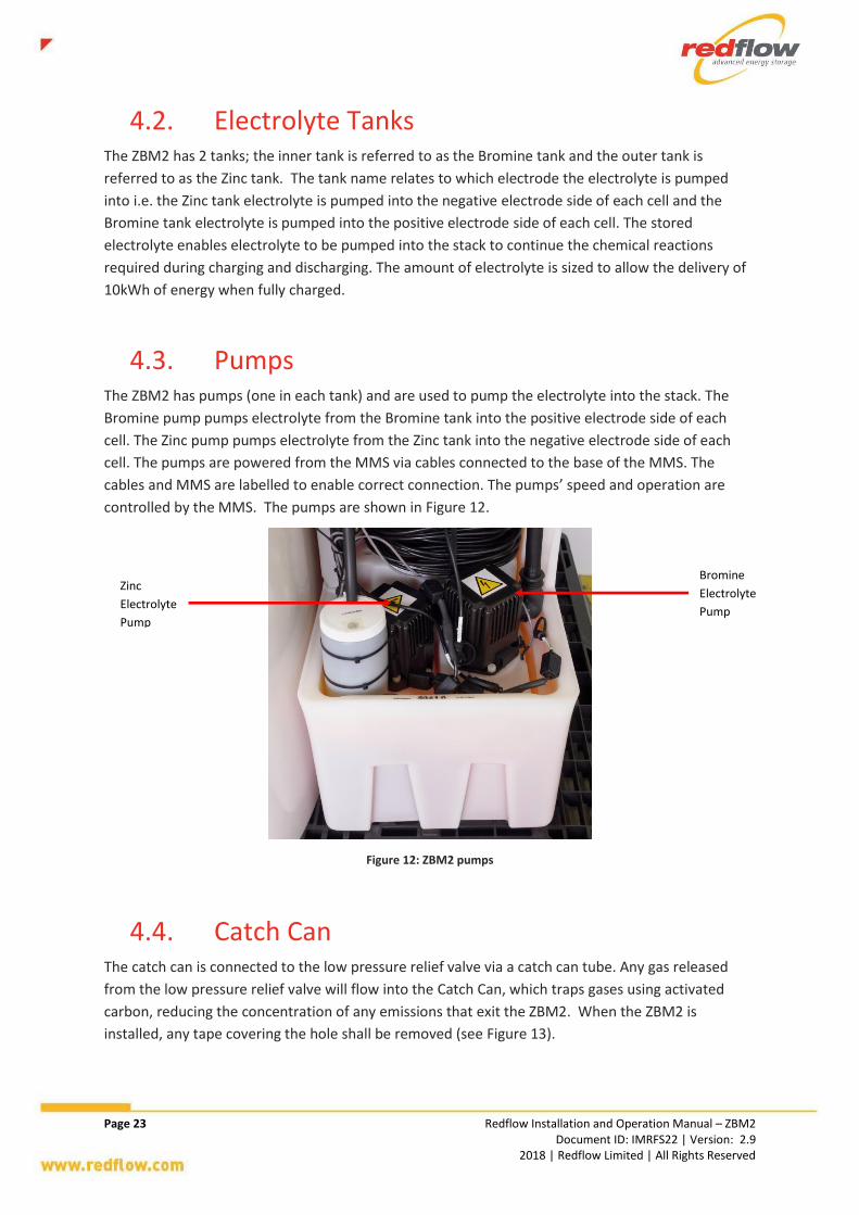
Figure 10: ZBM2 components (back and side view)
Direction of airflow
(air flows from back of
ZBM2 through ZBM2
cooling tubes towards
ZBM2 pumps at front
of ZBM2) Zinc Electrolyte Tank
Bromine
Electrolyte Tank
Lifting Straps
High Pressure
Relief Valve
Low Pressure
Relief Valve
Catch Can Inlet
Tube
MMS
Ambient
Temperature Sensor
Cooling Fan
Gas Handling
Units
Viton Tubes

Page 22 Redflow Installation and Operation Manual – ZBM2 Document ID: IMRFS22 | Version: 2.9 2018 | Redflow Limited | All Rights Reserved
Figure 11: ZBM2 terminal plates and pumps (front side view)
4.1. Electrode Stack The ZBM2 has 2 electrode stacks connected in parallel, with each stack made up of 30 cells in series.
The top terminal on each stack is the negative terminal and the bottom is the positive terminal. The
socket head cap screws that hold the terminal loops to the stack electrical connections are torqued
to 12Nm (8.9 ft-lb) and are marked to indicate the position of screw relative to the terminal loop for
correct torque. No electrical connections are to be added to the socket head cap screw connections,
see Figure 11.
Negative Terminal Loop
Positive Terminal Loop
Cooling tubes
ZBM2 Label
(Serial Number)
Tank Leak
Sensor Slot
Zinc
Electrolyte
Pump
Negative Terminals
Positive Terminals
Bromine
Electrolyte
Pump
Battery Temperature Sensor (behind catch can)
Catch Can
Top Caps
ZBM2 Serial Number
(stamped on tank)
Page 23 Redflow Installation and Operation Manual – ZBM2 Document ID: IMRFS22 | Version: 2.9 2018 | Redflow Limited | All Rights Reserved
4.2. Electrolyte Tanks The ZBM2 has 2 tanks; the inner tank is referred to as the Bromine tank and the outer tank is
referred to as the Zinc tank. The tank name relates to which electrode the electrolyte is pumped
into i.e. the Zinc tank electrolyte is pumped into the negative electrode side of each cell and the
Bromine tank electrolyte is pumped into the positive electrode side of each cell. The stored
electrolyte enables electrolyte to be pumped into the stack to continue the chemical reactions
required during charging and discharging. The amount of electrolyte is sized to allow the delivery of
10kWh of energy when fully charged.
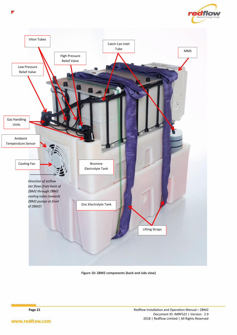
4.3. Pumps The ZBM2 has pumps (one in each tank) and are used to pump the electrolyte into the stack. The
Bromine pump pumps electrolyte from the Bromine tank into the positive electrode side of each
cell. The Zinc pump pumps electrolyte from the Zinc tank into the negative electrode side of each
cell. The pumps are powered from the MMS via cables connected to the base of the MMS. The
cables and MMS are labelled to enable correct connection. The pumps’ speed and operation are
controlled by the MMS. The pumps are shown in Figure 12.
Figure 12: ZBM2 pumps
4.4. Catch Can The catch can is connected to the low pressure relief valve via a catch can tube. Any gas released
from the low pressure relief valve will flow into the Catch Can, which traps gases using activated
carbon, reducing the concentration of any emissions that exit the ZBM2. When the ZBM2 is
installed, any tape covering the hole shall be removed (see Figure 13).
Zinc
Electrolyte
Pump
Bromine
Electrolyte
Pump

Page 24 Redflow Installation and Operation Manual – ZBM2 Document ID: IMRFS22 | Version: 2.9 2018 | Redflow Limited | All Rights Reserved
Figure 13: Catch can
4.5. Cooling Tubes The cooling tubes are used to cool the ZBM2 by running electrolyte through the tubes while the fan
is blowing cooler air over them.
4.6. Fan The fan blows air over the cooling tubes to lower the ZBM2 temperature. The operation of the fan is
controlled by the MMS which turns on and controls fan speed based on the battery temperature
measured by the Battery and Ambient Temperature Sensors.
4.7. Gas Handling Units The ZBM2 has 2 gas handling units (see Figure 14) that relieve pressure inside the tanks in the event
of an operational issue. The Zinc tank gas handling unit houses the low pressure relief valve, any gas
released from this valve is diverted to the catch can via the catch can tube (see Section 4.4). The
Bromine tank gas handling unit houses the high pressure relief valve, which provides redundancy in
the event of an issue with the low pressure relief valve.
Figure 14: Gas handling units
Tape to be
removed
Zinc tank gas
handling
Unit
Bromine tank
gas handling
unit
Page 25 Redflow Installation and Operation Manual – ZBM2 Document ID: IMRFS22 | Version: 2.9 2018 | Redflow Limited | All Rights Reserved
4.8. Lifting Straps The ZBM2’s lifting straps are provided with the ZBM to enable movement of the ZBM with
appropriate lifting devices, see Section 3.2 for more detail.
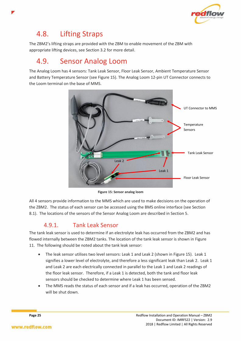
4.9. Sensor Analog Loom The Analog Loom has 4 sensors: Tank Leak Sensor, Floor Leak Sensor, Ambient Temperature Sensor
and Battery Temperature Sensor (see Figure 15). The Analog Loom 12-pin UT Connector connects to
the Loom terminal on the base of MMS.
Figure 15: Sensor analog loom
All 4 sensors provide information to the MMS which are used to make decisions on the operation of
the ZBM2. The status of each sensor can be accessed using the BMS online interface (see Section
8.1). The locations of the sensors of the Sensor Analog Loom are described in Section 5.
4.9.1. Tank Leak Sensor The tank leak sensor is used to determine if an electrolyte leak has occurred from the ZBM2 and has
flowed internally between the ZBM2 tanks. The location of the tank leak sensor is shown in Figure
11. The following should be noted about the tank leak sensor:
The leak sensor utilises two level sensors: Leak 1 and Leak 2 (shown in Figure 15). Leak 1
signifies a lower level of electrolyte, and therefore a less significant leak than Leak 2. Leak 1
and Leak 2 are each electrically connected in parallel to the Leak 1 and Leak 2 readings of
the floor leak sensor. Therefore, if a Leak 1 is detected, both the tank and floor leak
sensors should be checked to determine where Leak 1 has been sensed.
The MMS reads the status of each sensor and if a leak has occurred, operation of the ZBM2
will be shut down.
Tank Leak Sensor
Floor Leak Sensor
Temperature
Sensors
UT Connector to MMS
Leak 1
Leak 2

Page 26 Redflow Installation and Operation Manual – ZBM2 Document ID: IMRFS22 | Version: 2.9 2018 | Redflow Limited | All Rights Reserved
4.9.2. Floor Leak Sensor The floor leak sensor is used to determine if an electrolyte leak has occurred from the ZBM2 and has
flowed externally from the ZBM2. It should be installed under the ZBM2 tank during initial setup of
the ZBM2.
The leak sensor utilises two level sensors: Leak 1 and Leak 2 (shown in Figure 15). Leak 1
and Leak 2 are each electrically connected in parallel to the Leak 1 and Leak 2 readings of
the tank leak sensor. Therefore, if a Leak 1 is detected, both the tank and floor leak sensors
should be checked to determine where Leak 1 has been sensed.
The MMS reads the status of each sensor and if a leak has occurred, operation of the ZBM2
will be shut down.
To prevent false leak trips, the floor leak sensor should not be mounted on any conductive
surface. To assist with this, the floor leak sensor can be supplied with a cover.
It should be noted that if the floor leak sensor is mounted horizontally, Leak 2 will trip at
approximately the same time as Leak 1.
4.10. Power Cables The ZBM2 includes three Power Cables with waterproof connectors that provide DC power to the
ZBM2’s pumps and cooling fan from the MMS. These connections are internal to the ZBM2. The
three power cables are:
Cooling Fan (4-pin connector)
Zinc Pump (5-pin connector)
Bromine Pump (5-pin connector)
4.11. MMS The ZBM2 is a “smart” battery that comes with in-built intelligence to protect the ZBM2 battery and
allowing the user to gain more information about operation and any issues that arise.
Communication with the MMS is most effectively done using the BMS (see Section 4.12).
The MMS is mounted on to the ZBM2 battery’s terminals and is also where connections are made to
the ZBM2 from any external system or communications device. The required connections are shown
below in Figure 16 and Figure 17.

Page 27 Redflow Installation and Operation Manual – ZBM2 Document ID: IMRFS22 | Version: 2.9 2018 | Redflow Limited | All Rights Reserved
Figure 16: MMS connections
Figure 17: MMS terminal connections
4.12. BMS Redflow offers an additional accessory for use with the ZBM2 called the Battery Management
System (BMS) (see Figure 18). When powered and provided with an internet connection, a single
BMS allows the user to monitor, log and control operation of up to 12 ZBM2s via an online interface.
Maintenance Fuse
Negative (-) Bus
Terminal
Positive (+) ZBM2 Terminal (Internal ZBM2 connection) Regular Maintenance
Terminal (Internal ZBM2 Connection)
Negative (-) ZBM2 Terminal
(Internal ZBM2 connection)
Positive (+) Bus Terminal
COM Port #1
Cooling Fan and Bromine Pump Power (internal ZBM2
connections)
Analog Loom Communications
and Zinc Pump Power
(internal ZBM2 connection)
COM Port #2
MMS Box Cover

Page 28 Redflow Installation and Operation Manual – ZBM2 Document ID: IMRFS22 | Version: 2.9 2018 | Redflow Limited | All Rights Reserved
Figure 18: Redflow BMS
See Section 5 for connection information, and Sections 6.4, 6.5 and 8.1 for operational information.
4.13. Safety Guards and Covers The ZBM2 includes the following guards and covers to protect any personnel in the vicinity of the
ZBM2:
4.13.1. Terminal Collar
The IP2X-rated terminal collar prevents direct contact or accidental contact by other objects (e.g.
tools) with the ZBM2’s terminals when they are live (and potentially carrying hazardous currents and
voltages). The terminal collar can be removed from de-energised batteries for maintenance (see
Section 8) using a flat-head screwdriver.
The terminal collar is shown in Figure 19.
The terminal collar may only be removed by a ZBM2 trained installer.
Page 29 Redflow Installation and Operation Manual – ZBM2 Document ID: IMRFS22 | Version: 2.9 2018 | Redflow Limited | All Rights Reserved
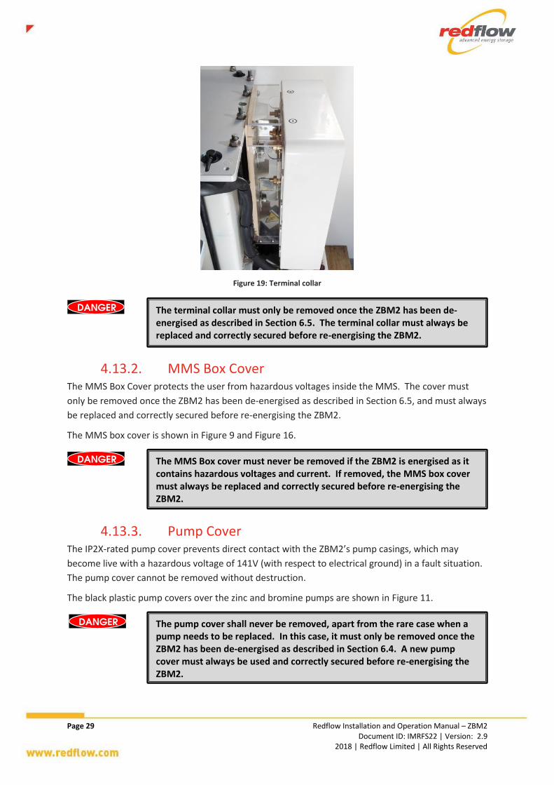
Figure 19: Terminal collar
4.13.2. MMS Box Cover The MMS Box Cover protects the user from hazardous voltages inside the MMS. The cover must
only be removed once the ZBM2 has been de-energised as described in Section 6.5, and must always
be replaced and correctly secured before re-energising the ZBM2.
The MMS box cover is shown in Figure 9 and Figure 16.
4.13.3. Pump Cover The IP2X-rated pump cover prevents direct contact with the ZBM2’s pump casings, which may
become live with a hazardous voltage of 141V (with respect to electrical ground) in a fault situation.
The pump cover cannot be removed without destruction.
The black plastic pump covers over the zinc and bromine pumps are shown in Figure 11.
The terminal collar must only be removed once the ZBM2 has been de-energised as described in Section 6.5. The terminal collar must always be replaced and correctly secured before re-energising the ZBM2.
The MMS Box cover must never be removed if the ZBM2 is energised as it contains hazardous voltages and current. If removed, the MMS box cover must always be replaced and correctly secured before re-energising the ZBM2.
The pump cover shall never be removed, apart from the rare case when a pump needs to be replaced. In this case, it must only be removed once the ZBM2 has been de-energised as described in Section 6.4. A new pump cover must always be used and correctly secured before re-energising the ZBM2.
Page 30 Redflow Installation and Operation Manual – ZBM2 Document ID: IMRFS22 | Version: 2.9 2018 | Redflow Limited | All Rights Reserved
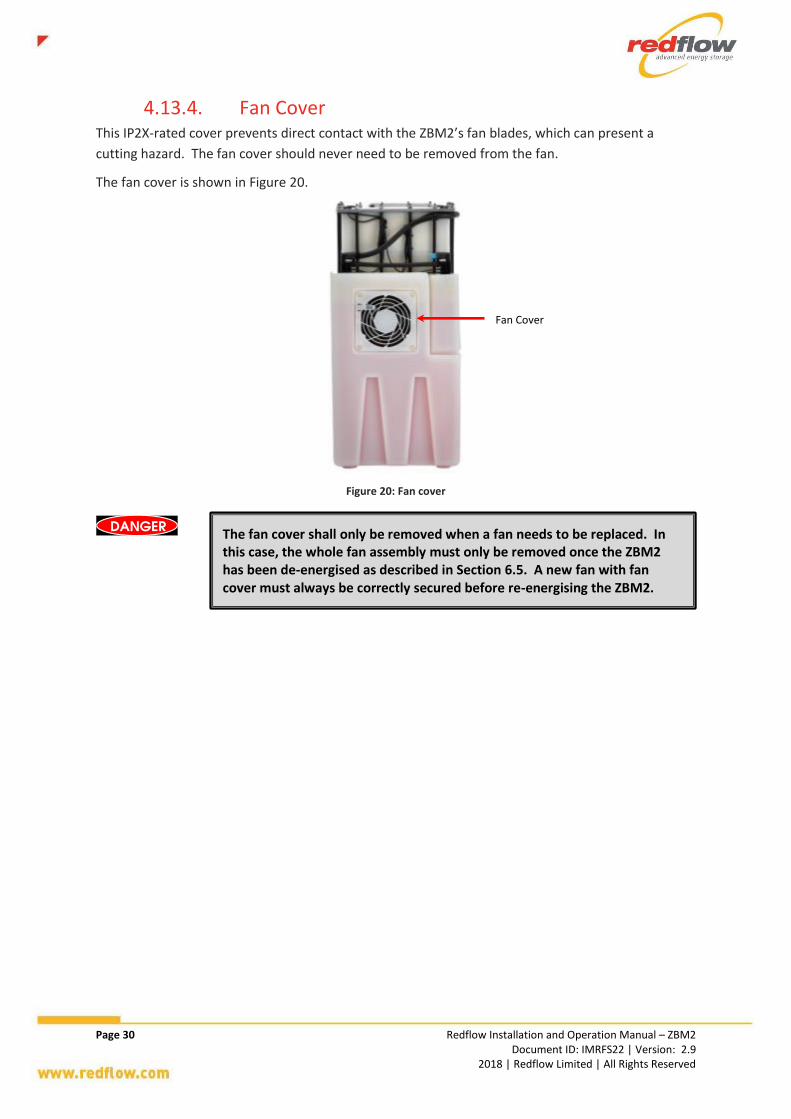
4.13.4. Fan Cover This IP2X-rated cover prevents direct contact with the ZBM2’s fan blades, which can present a
cutting hazard. The fan cover should never need to be removed from the fan.
The fan cover is shown in Figure 20.
Figure 20: Fan cover
The fan cover shall only be removed when a fan needs to be replaced. In this case, the whole fan assembly must only be removed once the ZBM2 has been de-energised as described in Section 6.5. A new fan with fan cover must always be correctly secured before re-energising the ZBM2.
Fan Cover

Page 31 Redflow Installation and Operation Manual – ZBM2 Document ID: IMRFS22 | Version: 2.9 2018 | Redflow Limited | All Rights Reserved
5. ZBM2 Installation and Connection This section lists the steps to perform in installing and connecting a ZBM2 into an energy storage
system.
Prior to this process, ensure the battery is taken out of the crate following the procedure in Section
3.3.
Step 1 Check for any electrolyte leaks both visually and by the presence of a chlorine-like
smell. If a leak is present, do not operate the ZBM2 and contact Redflow. Contact
details are provided inside the front cover of this manual. Leaks shall be cleaned up in
accordance with Appendix C. Appendix F contains the SDS for electrolyte as well as
global emergency contact details.
Step 2 Check all hoses (see Figure 21) are securely fitted with hose clamps and have not
disconnected or kinked during transport.
Figure 21: Hoses and hose clamps on the ZBM2
Step 3 Using a multimeter, check that the ZBM2 is fully discharged by ensuring the voltage
across the positive and negative ZBM2 terminals shown in Figure 22 (not the bus
terminals) is 0V when disconnected from any bus.
DC cabling must conform to local standards and regulations for a maximum battery current of 125A.
Ensure all connecting systems are completely de-energised during this process – do not start power until all steps in this section have been completed.
This process shall only be performed by personnel with the appropriate qualification as per local regulations and who have also received ZBM2 training.
Hose Clamps
Hoses

Page 32 Redflow Installation and Operation Manual – ZBM2 Document ID: IMRFS22 | Version: 2.9 2018 | Redflow Limited | All Rights Reserved
Figure 22: Positive and negative ZBM2 terminals
Step 4 Check the torque marks on the 4 ZBM2 terminal socket head cap screws line up
correctly. If the torque marks on the ZBM2 terminal connections do not line up
correctly remove the MMS, torque to 12Nm (8.9 lb-ft) and re-mark (see Figure 23).
Figure 23: ZBM2 terminal connections
Step 5 Remove the masking tape from the Catch Can’s vent hole (see Figure 24). The Catch
Can is designed to trap gas that is automatically diverted to it, before these gases reach
areas external to the ZBM2.
Correctly torqueing the battery terminal connections is critical. If they are not sufficiently tight, then heat can be generated during high current operation leading to ZBM2 failure.
It is recommended that a thermal imaging camera be used to monitor ZBM2 performance to ensure there are no such heat spots. ZBM2 failure arising from incorrectly torqued battery terminal connections is not covered by warranty.
Positive (+) ZBM2 Terminal (Internal ZBM2 connection)
Negative (-) ZBM2 Terminal
(Internal ZBM2 connection)
Negative Terminals
Positive Terminals

Page 33 Redflow Installation and Operation Manual – ZBM2 Document ID: IMRFS22 | Version: 2.9 2018 | Redflow Limited | All Rights Reserved
Figure 24: Catch Can masking tape removal
Step 6 Inspect to make sure that the ZBM2 Viton capillary tubes (see Figure 25) have not been
damaged during transportation or installation. Also check to make sure each end of the
tubes are securely connected and are not hanging free.
Figure 25: Viton tube
Step 7 Using a forklift, crane or other suitable lifting device (as shown in Figure 26), place the
ZBM2 into the prepared location with the recommended secondary spill containment.
The final location needs to have a flat, stable and fully-supported base surface for the
ZBM to be installed on. Check the two lifting straps are connected correctly to the
lifting device. The lifting mechanism shall lift both straps at the same time securely, and
in such a way as to keep the ZBM2 level with a minimum amount of swaying. Ensure
care is taken to avoid excessive force and damage to the ZBM2 during movement and
when placing the ZBM2 on to the prepared location.
It is recommended that Steps 1-6 be repeated once the ZBM2 is in its required location.
Completely
Remove Masking
Tape
Viton tube

Page 34 Redflow Installation and Operation Manual – ZBM2 Document ID: IMRFS22 | Version: 2.9 2018 | Redflow Limited | All Rights Reserved
Figure 26: Lifting the ZBM2
Step 8 Ensure all elements of the sensor analog loom are located in the correct positions. The
floor leak sensor should be placed in the recommended secondary spill containment at
the base of the ZBM2 (and should not rest on a conductive surface). The tank leak
sensor (see Figure 27) shall be installed on the Bromine pump. The temperature
sensors should already be installed in their correct locations (see Figure 28 and Figure
29). Ensure the sensor analog loom is connected to its terminal on the base of the
MMS (see Figure 30) via the UT connector.
Figure 27: Tank Leak Sensor location
Figure 28: Battery Temperature Sensor location
Figure 29: Ambient Temperature Sensor location
Figure 30: MMS connections
Battery Temperature Sensor
Slot (under catch can)
Zinc
Electrolyte
Pump
Catch Can
ZBM2 Lifting Straps
Lifting device
(e.g. forklift is shown here)
Tank Leak Sensor
Ambient
Temperature
Sensor
Cooling Fan
and Fan Cover
Analog Loom
Connection
Zn Pump
Br Pump
Fan
COM Port #1
COM Port #2
RJ45 Cap

Page 35 Redflow Installation and Operation Manual – ZBM2 Document ID: IMRFS22 | Version: 2.9 2018 | Redflow Limited | All Rights Reserved
Step 9 Ensure the power cables are connected to their corresponding MMS connections (see
Figure 30):
The 5-pin connector on the cable labelled ZN PUMP to the Zn connector on the
MMS.
The 5-pin connector on the cable labelled BR PUMP to the Br connector on the
MMS.
The 4-pin connector on the cable labelled FAN to the FAN connector on the MMS.
Step 10 Connect the BMS to the ZBM2 via the Communications ports on the MMS (see Figure
30). The Communications ports enable connection of Modbus RTU over RS-485.
This is done by using a Cat6 cable and cutting the RJ45 connector off one end. Using
the standard colour coding in the cable, strip the blue/white, solid blue and solid
orange (568A cables) or green (568B cables) wires. Connect these wires to the B, A and
SH ports respectively of the 485 section on the BMS as shown in Figure 31.
The BMS also requires a 9-65VDC power supply connected to the 9-65V + and – ports of
the BMS and an open internet connection to the RJ45 port as shown in Figure 31.
Figure 31: BMS connections
To connect to the MMS, connect the Cat6 cable from the BMS through the RJ45 boot in
the following sequence shown below in Figure 32. Firstly, feed the Cat6 cable through
the waterproof cap (a), followed by the rubber grommet (b) and the cable mount (c).
Blue/White = B Blue = A
Orange (568A) or Green (568B) = SH
DC + = + DC - = -
Internet Connection
Communications connection to ZBM2

Page 36 Redflow Installation and Operation Manual – ZBM2 Document ID: IMRFS22 | Version: 2.9 2018 | Redflow Limited | All Rights Reserved
Figure 32: Cat6 cable assembly
Finally, plug the Cat6 cable into the MMS via the data plug inside the rubber boot, on
the end of the cord. Tighten all parts of the RJ45 Boot to ensure the cable is secure and
waterproof as shown. Cover the second Communications port on the MMS with an
RJ45 cap if utilising a single MMS.
For connection of multiple ZBM2s, a daisy chain can be established by plugging the first
end of the Cat6 cable into Communication Port #2 of the first MMS and the second end
into the Communication Port #1 of the second MMS (see Figure 30). Cover the unused
Communication Port with an RJ45 cap.
Figure 33: MMS communication cable connected
Step 11 Connect positive and negative cables to the input bus terminals on the back of the
MMS (see Figure 34 and Figure 35) then to an appropriately sized circuit breaker
(maximum rating 125A). The 125A DC circuit breaker is not provided with the ZBM2,
and the cabling must be appropriately sized. Both the positive and negative terminal
cables are terminated with 8mm eyelets at the MMS.
This is done by first removing the terminal cover, then removing the washers and nuts
from the two studs of positive and negative bus terminals, as shown in Figure 35. Apply
carbon grease to the positive and negative bus studs.
Slide the positive (+ve) cable eyelet end over the Bus (+ve) terminal on the back of the
MMS. Place the Belleville washer onto the stud, ensuring that the Belleville washer is
curved towards the MMS Box so that the cone is pointing towards the electrode stack
(see Figure 36). Screw the nut over the Belleville washer, and tighten to 10Nm using a
torque wrench with a 13mm open head attachment. Repeat this process for the
negative (-ve) cable eyelet end over the Bus (-ve) terminal on the MMS.
c
b
a

Page 37 Redflow Installation and Operation Manual – ZBM2 Document ID: IMRFS22 | Version: 2.9 2018 | Redflow Limited | All Rights Reserved
Figure 34: MMS Connections
Figure 35: Bus cable connections
Figure 36: Belleville washer orientation (side view)
Mark the nut and MMS box on the positive and negative terminals with a permanent
marker to indicate that the connection has been correctly torqued to 10Nm (7.4ft-lb) as
shown in Figure 37.
Electrode
Stack
Mk Box back Brass
post
Nut
Belleville washer
ZBM2 Bus +ve Stud
MMS
Electrode Stack
ZBM2 Bus –ve Stud
Negative (-) Bus Terminal Positive (+) Bus Terminal

Page 38 Redflow Installation and Operation Manual – ZBM2 Document ID: IMRFS22 | Version: 2.9 2018 | Redflow Limited | All Rights Reserved
Figure 37: Torque marking
Step 12 Tidy the ZBM2’s lifting straps away neatly as shown in Figure 38. They remain on the
ZBM2.
Figure 38: Lifting straps
Step 13 Ensure all safety covers and guards are secured in place (refer to Section4.12 4.13 for a
list of covers). Refit the terminal collar, using the fasteners provided with it.
Step 14 Connect the de-energised energy storage system to the ZBM circuit breaker and
energise the system.
5.1. ZBM Set-Up Example: Inverter and Load The diagram below presents an example circuit that can be used to operate a ZBM2 (see Figure 39).
Figure 39: Example connections for testing the ZBM2
AC Line
AC Neutral
DC Positive
DC Negative
Grid Supply AC CB
Inverter ~/=
ZBM2
DC CB
125A
DC Load [0-58V / 0-100A]
DC CB

Page 39 Redflow Installation and Operation Manual – ZBM2 Document ID: IMRFS22 | Version: 2.9 2018 | Redflow Limited | All Rights Reserved
An explanation of each of the elements in Figure 39 is given below.
Grid supply: provides the power needed to support the load and charge the ZBM2.
Circuit Breaker (CB): circuit protection for AC/DC. These should be sized appropriately for
the inverter and load.
Inverter: converts the AC grid supply to DC for the ZBM2 and load.
ZBM2: charges when power is applied to terminals and discharges when a load is
connected and no other adequate source of power is available. Multiple ZBM2s could be
connected in parallel.
DC Load: the load that the battery and inverter needs to supply.
It is also important to note the following operational guidelines:
In order for the ZBM2 to undergo its Self-Maintenance Cycle (see Section 9.4.7 for more
information), it must first be completely discharged. This will occur automatically either
through an external load connected (faster and more efficient solution) or through its own
pumps and fan load (when no load is available). A fully charged battery will take 1-2 days
to fully discharge using its own pumps and fan load.
In order for the ZBM2 to complete its Self-Maintenance Cycle (see Section 9.4.7 for more
information), it must have external power from the inverter. This is to enable the ZBM2’s
pumps and MMS to operate even though the terminal voltage is ~0V.
The ZBM2 can be continuously powered without damage as it will automatically disconnect
the battery terminals from the bus when fully charged but will still source auxiliary power
from the bus.
Control and monitoring of the performance of the ZBM2 is best done using Redflow’s
additional BMS product.
Page 40 Redflow Installation and Operation Manual – ZBM2 Document ID: IMRFS22 | Version: 2.9 2018 | Redflow Limited | All Rights Reserved
6. ZBM2 Operation This section provides some background information about the operation of the ZBM2. At all times,
the ZBM2 must remain intact, with all fittings and components connected as new.
6.1. Operating “From Empty” The ZBM2’s default state of charge is fully discharged, and it can remain in this state indefinitely.
ZBM2s are charged from 0% state of charge up to the desired capacity at or below 100%, and then
discharged from there. Typically, constant power charge and discharge modes are used, but the
variable supply from a PV array on a cloudy day is equally effective.
6.2. ZBM2 Operating Modes The ZBM2 operates in one of two modes: Run Mode and Offline Mode.
Run Mode is the standard mode in which the ZBM2 is available to be charged and
discharged, and self-manages its regular maintenance cycle requirements and any
operational issues. The ZBM2 will automatically disconnect from the bus in a number of
operational events, such as overcurrent and overcharge.
Offline Mode can be set by the user to make the ZBM2 unavailable for use (will not
respond to requests until it is placed back into Run Mode) but will still be self-managed to
ensure the ZBM2 is in a safe state.
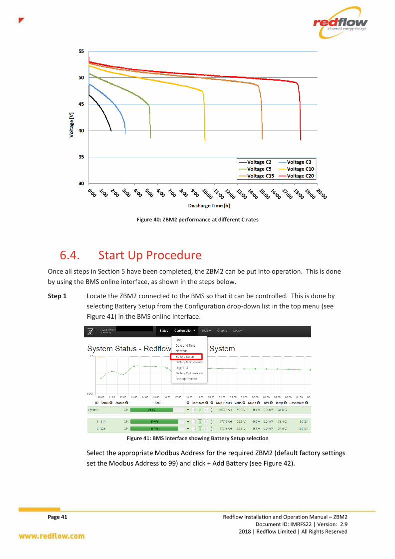
6.3. Discharge Curves The graph in Figure 40 below shows the performance of the ZBM2 at different C rates.
Page 41 Redflow Installation and Operation Manual – ZBM2 Document ID: IMRFS22 | Version: 2.9 2018 | Redflow Limited | All Rights Reserved
Figure 40: ZBM2 performance at different C rates
6.4. Start Up Procedure Once all steps in Section 5 have been completed, the ZBM2 can be put into operation. This is done
by using the BMS online interface, as shown in the steps below.
Step 1 Locate the ZBM2 connected to the BMS so that it can be controlled. This is done by
selecting Battery Setup from the Configuration drop-down list in the top menu (see
Figure 41) in the BMS online interface.
Figure 41: BMS interface showing Battery Setup selection
Select the appropriate Modbus Address for the required ZBM2 (default factory settings
set the Modbus Address to 99) and click + Add Battery (see Figure 42).

Page 42 Redflow Installation and Operation Manual – ZBM2 Document ID: IMRFS22 | Version: 2.9 2018 | Redflow Limited | All Rights Reserved
Figure 42: BMS interface showing Battery Setup screen
Step 2 Look for any ZBM2 firmware updates prior to operation. This is done by selecting
Upgrade Battery from the Tools drop-down list in the top menu (see Figure 43).
Figure 43: BMS interface showing Upgrade Battery selection
Select the ZBM2 or ZBM2s that require firmware updates by using the check boxes in
the Unit # section. Select the Bundled Firmware File, and click Upgrade. This is shown
in Figure 44.
Figure 44: BMS interface showing Battery Firmware Upgrade screen

Page 43 Redflow Installation and Operation Manual – ZBM2 Document ID: IMRFS22 | Version: 2.9 2018 | Redflow Limited | All Rights Reserved
Step 3 Put the ZBM2 into Run mode by going to the system Status page (see Figure 43) and
clicking the ZBM2 that should be started. On the ZBM2’s Battery Status page, click the
“bring battery online” link (see Figure 45). The Operational Mode will change from
“offline” to “run” after the user confirms this operation.
Figure 45: BMS interface showing how to bring a ZBM2 online
6.5. Shutdown Procedure The complete shutdown procedure below shall be used when shutting down the system for storage,
shipping, de-energised maintenance or ZBM2 replacement.
Step 1 Where possible, discharge the ZBM2 and perform a self-maintenance cycle. Note that
if a load is connected to the bus and the ZBM2 is fully or partially charged, the ZBM2
will discharge faster than if left to self-discharge only. During periods of self-
maintenance, the ZBM2 will electrically isolate itself from the MMS (and external DC
bus). As a result of there being no battery power available, its MMS requires external
power at all times while undergoing self-maintenance.
Step 2 Using the BMS online interface, put the ZBM2 into Offline mode. This is done by going
to the system Status page and clicking the ZBM2 that should be shut down. On the
ZBM2’s Battery Status Page, click the “take battery offline” link (see Figure 46). The
Operational Mode will change from “run” to “offline” after the user confirms this
operation.
Figure 46: BMS interface showing how to take a ZBM2 offline

Page 44 Redflow Installation and Operation Manual – ZBM2 Document ID: IMRFS22 | Version: 2.9 2018 | Redflow Limited | All Rights Reserved
Step 3 Disconnect the ZBM2 from any bus, load or charger connections by switching off any
connected circuit breakers.
Step 4 Using a multimeter, measure the voltage across the battery terminals to confirm that
the ZBM2’s terminal voltage is approximately 0V.

Page 45 Redflow Installation and Operation Manual – ZBM2 Document ID: IMRFS22 | Version: 2.9 2018 | Redflow Limited | All Rights Reserved
7. ZBM2 Wear and Failure Processes
7.1. Leaks The patio and segregation of the ZBM2 tanks have been designed so as to include a small
containment area for minor leaks. However, it should be noted that electrolyte could overflow from
the patio area so secondary containment should be used, and this should be taken into account in
system design (see Section 9.1.2).
Redflow has implemented leak detection in its ZBM2 to prevent damage to ZBM2s when leaks occur.
This functionality detects the presence of a leak in or near a ZBM2 via the use of the leak detectors
on the Analog Loom. In the event that a leak is detected, the MMS internals will disconnect the
charge/discharge contactor and stop both pumps.
7.2. Stack Degradation Gradual reduction in electrode conductivity occurs as the ZBM2 is used. This is the normal life
limiting process in the ZBM2. Eventually, the electrode resistance increases to the point where the
electrode stack needs to be replaced. If this occurs, contact Redflow for an approved part
replacement and procedure.
7.3. Incorrect Operation There are a number of ways the battery can be damaged due to incorrect handling and operation.
These are addressed throughout this Manual and must be addressed during training and in the
design of any Energy Storage Systems and their control electronics.
7.4. Electrolyte Contamination Electrolyte contamination can occur when the tank is not properly sealed, or from copper exposure
during a stack short circuit. Redflow has implemented internal functionality to halt operation of a
ZBM2 before a stack short circuit occurs.
Care should be taken to ensure that all electrolyte is stored in sealed containers such that no foreign
particles or items can contaminate it. Similarly, care should be taken when transferring electrolyte
to and from ZBM2s to ensure contamination does not occur.
7.5. Pump Failures Redflow has implemented pump failure detection internally to prevent damage to ZBM2s when
pumps operate incorrectly. This functionality will detect if pumps have seized or if they are running

Page 46 Redflow Installation and Operation Manual – ZBM2 Document ID: IMRFS22 | Version: 2.9 2018 | Redflow Limited | All Rights Reserved
when they are not supposed to be doing so. In the event that abnormal pump operation is detected,
the charge/discharge contactors will be disconnected and the Zinc pump will run (if that pump is still
operational). If this occurs, contact Redflow for an approved part replacement and procedure.
7.6. Electronics and Electrical These components have been designed to ensure sources of failure are minimised. It is important to
follow the instructions in this manual to ensure that the ZBM2 is not subjected to potentially
damaging electrical connections. During operation, the ZBM2 continually monitors hardware status
and operational parameters for unexpected issues. This information can be monitored with the BMS
online interface (see Section 8.1 for more information). The ZBM2 will attempt self-protection from
specific hardware electronics failures and requires manual intervention once the issue has been
resolved. The ZBM2 will attempt self-protection from these sorts of operational issues and attempt
reconnection once the fault has been cleared.
7.7. Over Temperature Over temperature inside the ZBM2 can damage it. The in-built cooling fan will automatically begin
operation when the ZBM2’s temperature exceeds 30 °C (86 °F). Operation will then be automatically
suspended when the ZBM2’s temperature exceeds 50°C (122 °F). It should be noted that if the
temperature of the electrolyte continues to significantly increase, this may result in high pressures
inside the ZBM2 as gases are evolved (see Section 9.3 for related design considerations).

Page 47 Redflow Installation and Operation Manual – ZBM2 Document ID: IMRFS22 | Version: 2.9 2018 | Redflow Limited | All Rights Reserved
8. ZBM2 Maintenance A systematic approach to preventative maintenance of the ZBM2 is required for warranty coverage.
Maintenance procedures are separated into condition monitoring and periodical procedures. A
checklist is provided in Appendix D that must be used to record maintenance activities.
If a part replacement is required, only Redflow-approved parts may be used; this is a requirement
for any warranty claims. If replacements are necessary, contact the supplier of the ZBM2.
It is recommended that adequate space to at least access the MMS side of the ZBM2 for electrical
connections be provided in all installations. There should also be adequate space provided to allow
individual ZBM2s to be removed and/or replaced at end of life, or for servicing of individual
components.
8.1. Ongoing Maintenance Ongoing condition monitoring maintenance involves remote monitoring of ZBM2 performance. If an
operational or hardware issue occurs with the ZBM2, a warning or failure alarm will be shown in the
BMS online interface. The Status page shows these alarms at a high level, as shown in Figure 47. The
individual Battery Pages show more detail about these alarms, as shown in Figure 48. These alarms
must be responded to in a timely manner and any external issues addressed. If left unattended,
these could cause damage to the ZBM2 and void any warranty claims.
Figure 47: BMS interface showing warning and failure alarms on the Status page
A fully completed and up-to-date checklist (provided in Appendix D), along with any supporting documentation for any abnormalities, is required in order to qualify for any ZBM2 warranty claim.

Page 48 Redflow Installation and Operation Manual – ZBM2 Document ID: IMRFS22 | Version: 2.9 2018 | Redflow Limited | All Rights Reserved
Figure 48: BMS interface showing details warnings and failures on the Battery Status page
8.2. Periodic Maintenance At least at annual intervals, the following maintenance tasks should be undertaken. Periodic
maintenance must be recorded in the checklist provided in Appendix D. If the ZBM2 is operating in
areas of high concentration of dust and dirt, it is recommended that on-site maintenance be
performed at shorter intervals.
Check the battery temperature reading is correct.
Check the air temperature reading is correct.
Check the cooling fan (part of the ZBM2) operates correctly.
Check the zinc electrolyte pump operates correctly.
Check the bromine electrolyte pump operates correctly.
Check the BMS interface to ensure the ZBM2 is running with no faults.
If any of the above checks produce sub-optimal or failing results, contact the supplier of the ZBM2
for Redflow-approved part replacement and procedures. Untrained maintenance on any of these
parts is discouraged and voids ZBM2 warranty.
DO NOT SHORT CIRCUIT BATTERY TERMINALS.
Any tools used MUST BE insulated and suitably rated and eye protection MUST BE worn. Remove all jewellery before performing any maintenance.
Ensure that the ZBM2 has been fully discharged, a regular maintenance cycle has been run, and shutdown has occurred as specified in Section 6.5 before the following maintenance tasks are undertaken.

Page 49 Redflow Installation and Operation Manual – ZBM2 Document ID: IMRFS22 | Version: 2.9 2018 | Redflow Limited | All Rights Reserved
Check the ZBM2 for any electrolyte leaks visually and by the presence of a chlorine-like
smell. If a leak is present, Appendix C provides more information on how to clean up
electrolyte spills. Appendix F contains the SDS for electrolyte and uncharged electrolyte.
Check all components of the ZBM2, including pumps and analog loom, for signs of corrosion
Ensure there are no kinks in Catch Can hoses
If any of the above checks produce sub-optimal or failing results, contact the supplier of the ZBM2
for Redflow-approved part replacement and procedures. Untrained maintenance on any of these
parts is discouraged and voids ZBM2 warranty.
Then, continue with the checks:
Check all ZBM2 hose clamps are securely fitted.
Check the ZBM2 connections are securely fitted.
Check that the ZBM2 battery terminals are correctly torqued at 10Nm (7.4 lb-ft). A thermal
imaging camera can be used to monitor ZBM2 performance (energised) to ensure there are
no heat spots, especially arising from incorrectly torqued battery terminals.
Clean the ZBM2 of any dust or dirt that has built up.
Check and remove any animal ingress
8.3. Cleaning No cleaning of the externals of the ZBM2 should be required. However, it is especially important
that users DO NOT USE the following liquids to clean ZBM2
Soap water
Alcohol
Any other detergents
Tap water may be used to clean the ZBM2 if required. The ZBM2 must be dried before packing.
Ensure that any and all safety guards or covers (see Section 4.13) that may have been removed from the ZBM2 during maintenance are replaced and secured before re-energising the ZBM2.

Page 50 Redflow Installation and Operation Manual – ZBM2 Document ID: IMRFS22 | Version: 2.9 2018 | Redflow Limited | All Rights Reserved
9. ZBM2 System Integration This section outlines some general guidelines for system integrators when using the ZBM2 in energy
storage systems (ESS).
9.1. System Design Guidelines – Safety There are several potential safety issues to consider when using the ZBM2 in an energy storage
system (ESS):
ZBM2 terminal voltage up to 58V DC during charge
Short circuit current of up to approximately 600A DC – conductors and protective devices
need to be designed accordingly
ZBM2 electrolyte is conductive and corrosive (2-3 pH) – avoid wetting electrical
components
Secondary containment for electrolyte (max 100L per ZBM2) is recommended (see Section
9.1.2)
Charged electrolyte contains bromine complex – manage fume risks (see Section 9.1.3)
ZBM2 operation may evolve hydrogen – manage explosive atmospheres (see Section 9.1.3)
The following safety systems should be designed into ZBM2-based ESS.
9.1.1. Shutdown Systems Automatic, manual and remote shutdown capabilities should be implemented in any ESS. Lethal
voltages exist inside these battery systems. Guidance on the ZBM2 shutdown procedure can be
found in Section 6.5.
9.1.2. Spillage Management System The presence of liquid electrolyte in the ZBM2 means that there is potential for a spill to occur.
While the ZBM2’s own tanks can hold small amounts of electrolyte from minor leaks, external spill
management equipment should be considered for the full electrolyte volume of 100L (26gal). The
ESS should include secondary spill containment to prevent any environmental contamination in the
case of spillage from the ZBM2 batteries. The electrolyte itself is water-based and can be diluted
with water. Any polyethylene container, bunding or bag can be used to contain the electrolyte.
Other plastics compatible with ZBM2 electrolyte include polypropylene, PVC and more expensive
materials including PVDF, Teflon and Viton. Note that many plastics including nylon and neoprene
are not compatible with the bromine-rich electrolyte. More detail on spills and managing them can
be found in Appendix C.
9.1.3. Hydrogen & Bromine Gas Management/Detection
System Low levels of gas may be emitted during operation of the ZBM2. As with all batteries that use water-
based electrolyte, some hydrogen can be generated inside the ZBM2 during operation. Although

Page 51 Redflow Installation and Operation Manual – ZBM2 Document ID: IMRFS22 | Version: 2.9 2018 | Redflow Limited | All Rights Reserved
Redflow’s ZBM2s are sealed systems, they have a pressure relief valve to manage internal pressures,
which can result in hydrogen and bromine gas escaping into the battery enclosure during
operational issues that result in high pressures inside the ZBM2. Further, any spills or leaks of
electrolyte will result in some bromine gas in the ESS. The levels of these gases are safe during
normal operation with no requirements for personal protective equipment (PPE) unless there is an
operational issue (see Section 2.1.4). If this occurs, the risks associated with hydrogen gas include a
potentially explosive environment in high concentrations, and the risks associated with bromine
gases can be found in the SDS in Appendix F. As such, ESS should include adequate ventilation (see
Section 9.2.3) and be monitored to ensure these gases remain at safe levels.
Further, each ZBM2 is equipped with a Catch Can (see Figure 11) to capture gases generated during
operation. Each Catch Can has a small hole that is covered with tape when delivered. The hole in
the Catch Can should be used to insert a non-kinkable PVC tube to connect the Catch Can to an area
safe to vent gases to (e.g. outside in open air). This tube must be made from non-kinkable PVC (e.g.
FlexPVC or Spaflex) and is not supplied by Redflow with the ZBM2.
Refer to Section 9.2.3 for more information about Ventilation Requirements.
9.1.4. Fire Control System An automatic fire control system may be required according to local regulations. However, the
ZBM2 should not be a fire risk. As a precaution, naked flames or any glowing heaters and other
devices must not be used in the vicinity of ZBM2 enclosures or battery rooms. Fire extinguishers
should also be installed in any ESS as a precaution, and be chosen for the materials in the ESS.
9.1.5. Noise Noise associated with the ZBM2’s operation is minimal, and has been measured to be maximum
77.0dB with background noise of 54.8dB. If noise is a concern, this should be accounted for in
system design.
9.2. System Design Guidelines – Mechanical Locating the ZBM2 inside an enclosure or a dedicated battery room needs to take into consideration
a range of issues.
ZBM2 weight
ZBM2 physical size
The ZBM2 is only designed for stationary applications. It contains different fluids that need
to separate and blend during different stages of ZBM2 operation. There are no baffles
installed in the electrolyte tanks to control the electrolyte in non-stationary applications.
The ZBM2 must be upright for operation, transportation and storage and be situated on a
flat, level surface. While it is a sealed system and will not leak if it is on its side, the ZBM2 is
not specifically designed to operate or remain for any length of time in these conditions.
The ZBM2 is not intended to withstand large forces and weights. Standing or leaning on
the ZBM2 should not occur.

Page 52 Redflow Installation and Operation Manual – ZBM2 Document ID: IMRFS22 | Version: 2.9 2018 | Redflow Limited | All Rights Reserved
The ZBM2 should be installed in an area that has sufficient ambient light and/or a similar
level of sufficient artificial light in order to allow for safe installation, operation and
maintenance.
The ZBM2 must be installed in clean and dry conditions, and protected from the natural
elements, and dirt and falling items.
Adequate insulation for the operating voltages and currents must be used on all materials
in the ESS.
Secondary containment: Required in case of electrolyte spills or leaks. Consideration should
also be given to the components of the ZBM2 and their locations that may be the source of
electrolyte leaks or ejection so as to contain this most effectively (see Section 7.1).
Enclosures must meet relevant standards and local environmental conditions.
Adequate airflow is provided to the ZBM2s and electronics (see Sections 9.2.1 and 9.2.3).
Correct ZBM2 orientation and adequate physical clearance should be provided around
ZBM2s to allow for easy maintenance and visual access (see Section 8 for maintenance
requirements). Consideration should also be given to the areas of the ZBM2 that may be
the source of electrolyte leaks or ejection so as to contain this most effectively.
System design must not restrict the flow of electrolyte in any piping or tubing included with
the ZBM2. If this flow is restricted, high internal pressures will build up inside the ZBM2,
leading to the pressure being relieved through the pressure relief valves. However, in the
case where both these valves fail, ZBM2 pressures in extreme cases may lead to a rupture
to relieve pressure. This will most likely occur at the stack-tank connection and system
design should take this into consideration.
9.2.1. Separation of ZBM2s and ESS Electronics The ZBM2 needs to be installed in a section of the ESS separate from the other electronics (with no
common flow of air), and with its own ventilation (see Section 9.2.3). However, in the case where
power electronics must be situated in very close proximity to ZBM2s, airtight enclosures for the
power electronics must be used. This is to prevent exposure to the power electronics of hydrogen
or bromine gas.
9.2.2. Corrosion Protection Due to the corrosive nature of the ZBM2’s electrolyte, any metals or similar materials that may
corrode should be corrosion-protected.
Copper bus bars should be Zinc plated and/or coated with polyethylene.
Do not use uncoated steel including stainless steel. Coating options are: PVC, powder
coating, zinc plating, hot dipped galvanised.
Do not use stainless steel fasteners use zinc plated or galvanised fasteners.
Aluminium should be anodised (>20 micron).
Cables ties shall be polypropylene not nylon.
If building an enclosure contact Redflow for further support.

Page 53 Redflow Installation and Operation Manual – ZBM2 Document ID: IMRFS22 | Version: 2.9 2018 | Redflow Limited | All Rights Reserved
9.2.3. Ventilation Requirements The ZBM2 is not intended for use in explosive environments. ZBM2s must never be installed in
airtight enclosures. Ventilation of any enclosures or battery rooms containing ZBM2s is required
both for thermal management (see Section 9.3) and management of hydrogen and bromine gases
that can be emitted during some operational issues. As a guide for gas management, the European
Standard, EN 50 272-2, should be followed as ZBM2 gas emissions are similar to those for lead-acid
batteries. Issues to be considered include adequate free space between ZBM2s and other
components, adequate airflow (e.g. via the use of fans), and adequate placement of vents, windows
and other openings.
The recommended airflow rates outlined in Table 2 for thermal management far exceed the airflow
requirements to address any gas emissions. Airflow shall be directed in such a way so as not to
oppose the ZBM2’s cooling fan path as shown in Figure 9.
Due to the risks posed by inadequate airflow leading to a build-up of gases during an operational
issue, it is highly recommended that any ESS including ZBM2s be fitted with an airflow sensor at least
for those ESS relying on artificial (not natural) airflow to alert users if the ZBM2 installation is not
receiving adequate airflow.
9.2.4. Securing ZBM2s The ZBM2 is not supplied with any specific lock-down mechanisms as it is designed for stationary
applications. If the system is required to be rated for high vibration or earthquake zones, then
additional mechanical methods of securing the ZBM2 will need to be implemented. Personnel
should not approach or be in the vicinity of the ZBM2 when it is experiencing high vibrations.
9.3. System Design Guidelines – Thermal Management
Management of the thermal load generated as the battery discharges and charges is normally
achieved through fan-forced ventilation and by allowing the battery electrolyte temperature to rise
during operation.
The most important criterion is to design for a sufficient flow of air through the ZBM2’s fan cooling
system. The ZBM2 is not a battery that can be installed in a sealed container since a significant
amount of heat needs to be dissipated. The discharge of a single ZBM2 can generate as much as
2kWh of heat. If this discharge occurs over 2 hours, then heat is being generated at 1kW per hour.
Thermal design considerations include:
Redflow recommends that enclosures and battery rooms are designed for at least the
airflow rate stated in Table 2 for adequate thermal management.
The presence of fans can have implications on the noise level generated by the ESS, and this
needs to be taken into consideration during enclosure design, especially if the ESS is to be
installed in close proximity to work or sleeping areas.
An air-conditioned enclosure can be utilized; however, the same ventilation requirements
are required as for sealed lead-acid batteries.

Page 54 Redflow Installation and Operation Manual – ZBM2 Document ID: IMRFS22 | Version: 2.9 2018 | Redflow Limited | All Rights Reserved
The mass of the ZBM2 can be used to absorb some of the heat generated during operation.
ZBM2 operating temperature range (see Table 1).
Cables and their insulation connecting to the ZBM2 should be capable of withstanding
temperatures of 70-110°C as cables may reach these temperatures at high currents.
It should be noted that significantly high ZBM2 temperatures can lead to gas evolution, high internal
ZBM2 pressures and in extreme cases, a rupture to relieve pressure should both the pressure relief
valves fail. This will most likely occur at the stack-tank connection and system design should take
this into consideration.
9.3.1. Temperature Considerations ZBM2 operation will automatically be suspended when the battery temperature reaches 50°C
(122°F) to prevent the ZBM2 operating in extreme ambient temperatures. It should be noted that
depending on a range of operating parameters, including enclosure design, ventilation and
charge/discharge rates, the battery temperature is in most cases higher than the ambient
temperature in lower ambient temperatures.
The most effective way to maintain the ZBM2 within its acceptable temperature range is for the ESS
to use fan ventilation when ambient temperature conditions are hot. Well-ventilated enclosures or
battery rooms and slower charge/discharge rates will also result in lower battery temperatures.
Active cooling with chillers or air conditioners is generally not required. When the ambient
temperature is cold, it is advised that heaters should be used to raise the ambient temperature
around the ZBM2. Further, operating the ZBM2, especially at full power, will raise its internal
temperature compared to when it is not operational.
9.4. System Design Guidelines – Electrical The ZBM2 is a battery and needs to be installed as one of many electrical components in an ESS to
provide a useable solution for end-customers.
A typical ZBM2-based ESS, which is developed by System Integrator partners, consists of:
Batteries, either single or multiple ZBM2s, or a combination of ZBM2s and other types of
batteries.
BMS for communication with the ZBM2s (see Sections 4.12 and 9.5 for more information)
A bi-directional Power Conversion System (PCS) which may be DC-AC for typical grid-
connected applications or it may be DC-DC for some off-grid applications, e.g. Telecom
applications.
A Unit Master controller with an appropriate communications link and user interface to
allow the end customer to operate the ESS.
Grid-interconnection components as required by the application (e.g. transformers).
It is recommended that the top stack plate be grounded via the use of the grounding hole
provided to avoid any possible static charge building up or the plate to be shorted to higher
voltages during a fault condition.

Page 55 Redflow Installation and Operation Manual – ZBM2 Document ID: IMRFS22 | Version: 2.9 2018 | Redflow Limited | All Rights Reserved
A list of operational electrical parameters to be adhered to for warranty (see Redflow website for
warranty terms) purposes can be found in Table 1.
9.4.1. Voltages A critical element when designing for the use of ZBM2s is to understand the charge and discharge
voltages of the ZBM2. While the ZBM2 has been designed to operate with nominal 48V devices (such
as inverters), the voltages produced can be outside the voltage ranges of some systems that have
been designed specifically for 48V lead-acid batteries. Figure 49 shows the typical voltages produced
by the ZBM2 during charging and discharging. The ZBM2 can be discharged down to a voltage of 40V
at which the battery automatically disconnects from the DC bus.
Figure 49: Excerpt from Figure 50 showing ZBM2 voltage profile
While the battery voltages are classified as extra low voltage (ELV) in Australia, care should be taken
in design to ensure systems are safe according to local regulations.
9.4.2. Currents The charge current needs to be limited to conform to the maximum charging power limit per ZBM2
specified in Table 1. The MMS will disconnect from the bus if a current above 50A (or a voltage
above 60V) is measured, so the maximum charging current should be set to a value below 50A.
The maximum continuous discharge current is the current required to produce the maximum
continuous output power as stated in Table 1. Operating the ZBM2 at a higher level will void any
warranty claim (see Redflow website for warranty terms). The discharging current at which the
MMS will disconnect from the bus is 125A. The disconnection will occur after detecting a current of:
125A for 13 minutes, or
126A for 60 seconds, or
128A for 5 seconds, or
instantaneously for 130A or above
All fault protection equipment (such as fuses and circuit breakers) should be chosen and designed
for fault currents of 125A and above, while taking into account the level of normal operating
currents stated in this section.
It should be noted that when multiple ZBM2s are operated in parallel, the maximum charge and
discharge currents are cumulative, e.g. two ZBM2s can be charged with a maximum of 100A (50A
each). If one of the multiple ZBM2s disconnects from the bus (e.g. because it has reached 100% SOC
or it requires self-maintenance soon (see Section 9.4.7)), then the maximum charging current will
reduce by 50A. As such, any chargers connected to the bus should be able to prevent a higher

Page 56 Redflow Installation and Operation Manual – ZBM2 Document ID: IMRFS22 | Version: 2.9 2018 | Redflow Limited | All Rights Reserved
power still being pushed into the bus, e.g. by voltage control or by limiting the charger current based
on the number of ZBM2s connected to the bus).
9.4.3. Power Output The ZBM2’s power ratings are stated in Table 1. The duration of the ZBM2’s peak discharge power
depends on various parameters including the battery’s current state of charge, age and
temperature. A new ZBM2 at 100% state of charge and operating at room temperature will provide
peak power for the duration reported in Table 1.
9.4.4. Energy Output The ZBM2 energy capacity is stated in Table 1. Unlike lead-acid batteries, the ZBM2 is designed to
provide 100% of the available energy every day.
9.4.5. Response Time The full load response time of a ZBM2 is fast when the pumps are running, but requires a short start-
up period when operating from empty. The ZBM2 operates in the same manner as any other
battery, and can swap from full power charging to full power discharging almost instantaneously.
9.4.6. Efficiency Gross energy efficiency of the ZBM2 is up to approximately 80% without ancillary components.
However, the cumulative effect of inverters, cooling systems, and additional power electronics will
reduce overall AC-AC efficiency to lower levels.
9.4.7. Self-Maintenance Self-maintenance is the process of stripping all zinc from the electrodes of the ZBM2. The ZBM2
needs to be used in such a way that it can undergo self-maintenance regularly. It is a condition of
any warranty claim (see Redflow website for warranty terms) that the ZBM2 has undergone self-
maintenance at the frequency specified in Table 1. The self-maintenance process in a standard
ZBM2 cycle is shown in Appendix F.
Key aspects of the self-maintenance process include:
The ZBM2 will automatically enter, run and exit self-maintenance mode using its MMS. The
user has control over the timing of the self-maintenance cycle by utilising the BMS
interface. This is accessed by navigating to the Battery Maintenance page in the
Configuration drop down menu.
In systems with multiple ZBM2s, by default, only one ZBM2 at a time can perform self-
maintenance. Using the scheduling feature in the BMS described later in this section, this
can be modified to allow more than one ZBM2 to perform self-maintenance at one time.
In the event that the communication link between the BMS and ZBM2 is lost, the MMS has
an inbuilt safety measure to ensure self-maintenance is performed at sufficient intervals to
prevent damage to the ZBM2.
To minimise time to complete the maintenance cycle, the ZBM2 must be fully discharged
before entering self-maintenance mode.

Page 57 Redflow Installation and Operation Manual – ZBM2 Document ID: IMRFS22 | Version: 2.9 2018 | Redflow Limited | All Rights Reserved
When required, the ZBM2 will flag that it needs to start the self-maintenance process in the
next 24 hours. It will automatically prevent further charging and only allow discharge to
occur. The ZBM2 will then continue to discharge until it is sufficiently discharged to
automatically enter the Self-Maintenance state, or the 24 hours has expired.
When it is not connected to a BMS, if the ZBM2 is not fully discharged when the 24 hours
has expired, the ZBM2 will disconnect from the bus and utilise its own pumps and fan as
loads into which to self-discharge to enable it to fully discharge. Note that this can take
several days if the ZBM2 is fully charged.
When connected to a BMS, the ZBM2 will continue to remain in the discharge-only phase
past the 24 hour time period until such time that the ZBM2 has been fully discharged.
After discharge is completed, excess zinc is automatically stripped from the ZBM2’s
electrodes. The user should allow two-three hours for a full self-maintenance cycle to be
performed by a ZBM2 after it has discharged.
The MMS box requires external power at all times while undergoing self-maintenance. This
is because during these periods of self-maintenance, the ZBM2 will electrically isolate itself
from the MMS (and external DC bus).
If there is no external power available to the ZBM2 when it begins the self-maintenance
cycle or external power is lost during self-maintenance, the ZBM2 will power down. When
external power is returned, the ZBM2 will continue where it stopped in the self-
maintenance cycle.
If the application requires a continuous source of battery power to be available, the system should
be designed with at least 2 ZBM2s or as a hybrid with e.g. a different form of power back-up.
Single ZBM2 ESS – means that there will be no voltage on the ZBM2 terminals during the
self-maintenance period.
Multi-ZBM2 ESS – the BMS can arrange the stripping program such that only one ZBM2 is
undergoing self-maintenance at a time and the remaining ZBM2s are available.
Self-maintenance can be optimised by noting the following:
Discharge all stored energy into the load prior to running the self-maintenance cycle. This
means that the stored energy can be used in a “useful” way (i.e. it is not wasted) and the
ZBM2 will not be out of service for any additional period of time to self-discharge.
Strip cycles can be run during times when the battery does not need to operate but a
power source is still available. E.g. in a grid-connected solar shifting application, the self-
maintenance cycle can be done in the early hours of the morning when the battery has
been completely discharged, there is no solar power available to charge the batteries and
grid power can be less expensive.
9.4.8. Parallel Arrangements of ZBM2s Multiple ZBM2s can be connected in parallel arrangements. The optimal arrangement often
depends on the voltage, current and other power electronics requirements of the ESS. By default,
the ZBM2 comes with the standard MMS for parallel connection. ZBM2s should not be connected in
series.

Page 58 Redflow Installation and Operation Manual – ZBM2 Document ID: IMRFS22 | Version: 2.9 2018 | Redflow Limited | All Rights Reserved
9.5. System Design Guidelines – Communications Communications with each ZBM2 is more effectively done using a BMS with an internet connection.
This provides an online interface to one or multiple ZBM2s in a system and can communicate with
each ZBM2 individually using unique MODBUS addresses.
It is important to note that 1 BMS can be used to communicate with up to 10 ZBM2s in one system.
If the system being designed has more than 10 ZBM2s, an RS485 repeater can be used to enable the
single BMS to communicate with a higher number of ZBM2s.
The BMS can also connect to other components in the larger energy system, including energy
management systems and inverters, to enable control of the ZBM2s from those components.

Page 59 Redflow Installation and Operation Manual – ZBM2 Document ID: IMRFS22 | Version: 2.9 2018 | Redflow Limited | All Rights Reserved
Abbreviations and Appendix ADefinitions
The following acronyms, abbreviations and terms are defined here within the context of this manual.
Term Definition oC Degrees Celsius
oF
Degrees Fahrenheit
A Amp
AC Alternating Current
Ah Amp Hour
BMS Battery Management System
DC Direct Current
ELV Extra-Low Voltage
ESS Energy Storage System
GHU Gas Handling Unit
I Current
in Inch
IBC Intermediate Bulk Container
IPxx International Protection Rating
kg Kilogram
kW Kilowatt
kWh Kilowatt hour
lb Pound
lb-ft Pound-force-feet
LV Low Voltage
mm millimetre
MMS Module Management System
Nm Newton metre
PPE Personal Protective Equipment
SDS Safety Datasheet
SOC State of Charge
V Volt
W Watt
ZBM2 Zinc-Bromine Module 2

Page 60 Redflow Installation and Operation Manual – ZBM2 Document ID: IMRFS22 | Version: 2.9 2018 | Redflow Limited | All Rights Reserved
EC Declaration of Appendix BConformity

Page 61 Redflow Installation and Operation Manual – ZBM2 Document ID: IMRFS22 | Version: 2.9 2018 | Redflow Limited | All Rights Reserved
Addressing ZBM2 Appendix CElectrolyte Spills/Leaks
This section provides guidance on how to assess the severity of an electrolyte spill or leak, and how
to manage the clean-up.
1. Electrolyte Spill or Leak Classification
It is necessary to assess and classify the severity of an electrolyte spill in order to be able to address
it effectively. The table below provides guidelines for determining if the spill or leak is minor or
major.
Characteristic Minor Spill/Leak Major Spill/Leak
Volume Less than 1 (one) litre More than 1 (one) litre
Flow Rate Slow drip or no visible flow High flow rate
Smell No strong smell Strong chlorine-like smell
Colour Clear or light yellow Deep red
Location No liquid is near electrical connections Liquid is near electrical connections
2. Electrolyte Spill or Leak Clean Up
This section provides guidelines for cleaning up a ZBM2 electrolyte spill or leak. All personnel
involved in clean-up activities must be aware of the content of the Redflow Battery Electrolyte SDS
in Appendix E.
Step 1 Assess the Severity of the Spill/Leak
Using the information in table above, assess the severity of the spill or leak as minor or major.
If the spill/leak is minor, proceed to Step 2.
If the spill/leak is major, proceed to Step 3.
Step 2 Minor Electrolyte Spill/Leak Clean Up
Step 2.1 Apply personal protection equipment.
Step 2.2 If the spill/leak is associated with a ZBM2, pause the operation of the ZBM2 (if the
MMS has not already done this).
Inspect the ZBM2 for the cause or source of the leak.
Using rags or disposable wipes, clean up the visible electrolyte.
Discharge the ZBM2 safely.
Manage all clean up materials as hazardous waste by placing them in an acid debris
waste accumulation container.
Contact Redflow support for advice on how to proceed.

Page 62 Redflow Installation and Operation Manual – ZBM2 Document ID: IMRFS22 | Version: 2.9 2018 | Redflow Limited | All Rights Reserved
Step 2.3 If the spill is not associated with a ZBM2, for example, electrolyte is spilt from its
container, use rags or disposable wipes to clean up the electrolyte.
Apply absorbent (as specified in Section 3 of Appendix C below) to neutralise
remaining electrolyte.
Manage all clean up materials as hazardous waste by placing them in an acid debris
waste accumulation container.
Step 3 Major Electrolyte Spill/Leak Clean Up
Step 3.1 Alert colleagues that the electrolyte spill/leak has occurred and if a strong chlorine-
like odour is evident, evacuate the hazardous area.
Step 3.2 Apply personal protection equipment.
Step 3.3 If the spill/leak is associated with a ZBM2, stop the operation of the ZBM2.
Isolate electrical connections.
Inspect the ZBM2 for the cause or source of the leak and if possible prevent further
leakage from occurring.
Using rags or disposable wipes, clean up the visible electrolyte.
Apply absorbent (as specified in Section 3 of Appendix C below) to neutralise
remaining electrolyte.
Manage all clean up materials as hazardous waste by placing them in an acid debris
waste accumulation container.
If possible, discharge the ZBM2 safely.
Actively ventilate the affected area.
Contact Redflow support for advice on how to proceed.
Step 3.4 If the spill/leak is not associated with a ZBM2, inspect for the cause or source of the
spill and if possible prevent further spillage from occurring. This may require the use
of other appropriate containers (e.g. polyethylene) to contain the spill.
Using rags or disposable wipes, clean up the visible electrolyte.
Apply absorbent (as specified in Section 3 of Appendix C below) to neutralise
remaining electrolyte.
Manage all clean up materials as hazardous waste by placing them in an acid debris
waste accumulation container.
3. Clean Up Materials
Rags and disposable wipes are suitable for cleaning up electrolyte.
Neutralising Electrolyte - uncharged
Commercial absorbents or acid neutraliser absorbents (that have a significant colour change to
signify complete neutralisation of acids) can be used for electrolyte clean-up.
Lime or baking soda can also be used to neutralise acid and therefore an electrolyte spill.
Neutralising Electrolyte – charged

Page 63 Redflow Installation and Operation Manual – ZBM2 Document ID: IMRFS22 | Version: 2.9 2018 | Redflow Limited | All Rights Reserved
Household grade ammonia (~10%) solution can be used to neutralise bromine complex, or charged
electrolyte spills. Caution must be exercised, to prevent a violent exothermic reaction. Add ammonia
solution slowly to the spilt electrolyte.
NOTE: All materials to be used in contact with electrolyte in future need to be rinsed of any acid,
ammonia or other neutralising agents prior to re-use to avoid chemical imbalance in the electrolyte.
NOTE: Any disposal of materials that have come into contact with electrolyte must be disposed of in
accordance with local laws and regulations.

Page 64 Redflow Installation and Operation Manual – ZBM2 Document ID: IMRFS22 | Version: 2.9 2018 | Redflow Limited | All Rights Reserved
Maintenance Checklist Appendix D
Annual Checks
Date
Check the BMS interface for any warning or failure alarms
Check the battery temperature reading is correct
Check the air temperature reading is correct
Check the cooling fan operates correctly
Check the zinc electrolyte pump runs
Check the bromine electrolyte pump runs
Check the ZBM2 for any electrolyte leaks visually and by
the presence of a chlorine-like smell.
Check the ZBM2 for signs of corrosion
Check hoses connected to the catch can are not kinked.
Check ZBM2 hose clamps are securely fitted
Check the ZBM2 connections are securely fitted
Check that the ZBM2 battery terminals are correctly
torqued at 10Nm (7.4 lb-ft).
Clean the ZBM2 of any dust or dirt
Check and remove any animal ingress

Page 65 Redflow Installation and Operation Manual – ZBM2 Document ID: IMRFS22 | Version: 2.9 2018 | Redflow Limited | All Rights Reserved
Standard Cycle Appendix EFigure 50 shows Redflow’s Standard ZBM2 cycle. This same standard cycle is run in case of a
warranty claim or to determine the state of health of a ZBM2 in the field. The standard cycle is
always run starting with a completely discharged ZBM2 (i.e. Self-Maintenance Cycle run immediately
before the standard cycle is run). The minimum efficiency performance requirement is given in
Table 1.
There are three operating modes that the ZBM2 goes through during this standard cycle:
1. Charging (9.2 hour period from 0 to 9.2 hours):
Current (blue trace, using right axis) at -25A DC (negative = charging) for 9.2 hours.
2. Discharging (10 hour period from 9.2 to 19.2 hours):
Current ranges from 25A DC to 0A DC as the voltage (red trace, using left axis) falls
from 52V DC to 0V DC.
The ZBM2 continues to discharge until the battery current is very close to 0A, and
the ZBM2 is empty.
3. Self-Maintenance (0.5 hour period from 19.2 to 19.7 hours):
This process is optional, but must be run at least as often as is specified in Table 1.
More information about this can be found in Section 9.4.7).
Figure 50: An example of the Redflow ZBM2’s Standard Cycle

Page 66 Redflow Installation and Operation Manual – ZBM2 Document ID: IMRFS22 | Version: 2.9 2018 | Redflow Limited | All Rights Reserved
Redflow ZBM2 Appendix FSafety Data Sheet
This section contains the safety datasheet for the ZBM2.
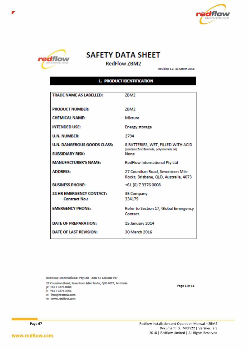
Page 67 Redflow Installation and Operation Manual – ZBM2 Document ID: IMRFS22 | Version: 2.9 2018 | Redflow Limited | All Rights Reserved

Page 68 Redflow Installation and Operation Manual – ZBM2 Document ID: IMRFS22 | Version: 2.9 2018 | Redflow Limited | All Rights Reserved

Page 69 Redflow Installation and Operation Manual – ZBM2 Document ID: IMRFS22 | Version: 2.9 2018 | Redflow Limited | All Rights Reserved

Page 70 Redflow Installation and Operation Manual – ZBM2 Document ID: IMRFS22 | Version: 2.9 2018 | Redflow Limited | All Rights Reserved

Page 71 Redflow Installation and Operation Manual – ZBM2 Document ID: IMRFS22 | Version: 2.9 2018 | Redflow Limited | All Rights Reserved

Page 72 Redflow Installation and Operation Manual – ZBM2 Document ID: IMRFS22 | Version: 2.9 2018 | Redflow Limited | All Rights Reserved

Page 73 Redflow Installation and Operation Manual – ZBM2 Document ID: IMRFS22 | Version: 2.9 2018 | Redflow Limited | All Rights Reserved

Page 74 Redflow Installation and Operation Manual – ZBM2 Document ID: IMRFS22 | Version: 2.9 2018 | Redflow Limited | All Rights Reserved

Page 75 Redflow Installation and Operation Manual – ZBM2 Document ID: IMRFS22 | Version: 2.9 2018 | Redflow Limited | All Rights Reserved

Page 76 Redflow Installation and Operation Manual – ZBM2 Document ID: IMRFS22 | Version: 2.9 2018 | Redflow Limited | All Rights Reserved

Page 77 Redflow Installation and Operation Manual – ZBM2 Document ID: IMRFS22 | Version: 2.9 2018 | Redflow Limited | All Rights Reserved

Page 78 Redflow Installation and Operation Manual – ZBM2 Document ID: IMRFS22 | Version: 2.9 2018 | Redflow Limited | All Rights Reserved

Page 79 Redflow Installation and Operation Manual – ZBM2 Document ID: IMRFS22 | Version: 2.9 2018 | Redflow Limited | All Rights Reserved

Page 80 Redflow Installation and Operation Manual – ZBM2 Document ID: IMRFS22 | Version: 2.9 2018 | Redflow Limited | All Rights Reserved

Page 81 Redflow Installation and Operation Manual – ZBM2 Document ID: IMRFS22 | Version: 2.9 2018 | Redflow Limited | All Rights Reserved

Page 82 Redflow Installation and Operation Manual – ZBM2 Document ID: IMRFS22 | Version: 2.9 2018 | Redflow Limited | All Rights Reserved

Page 83 Redflow Installation and Operation Manual – ZBM2 Document ID: IMRFS22 | Version: 2.9 2018 | Redflow Limited | All Rights Reserved
Document Revision Appendix GHistory
Version Date Details of Change Author
1.0 Original Original release for ZBM Gen2.9 MNM
2.0 20 Nov 2015 Updates for ZBM2 MNM
2.1 10 Jun 2016 Updates – new SDS, Section 6 – Communications Protocol, 5kW power.
MD
2.2 23 June 2016 Complete review by BOC New pictures Addition of Ethernet connection info
MD
2.3 20 July 2016 Review by MG Change of temperature range
MD
2.4 21 July 2016 Further review by BO MD
2.5 MD
2.6 31 August 2016 MD
2.7 10 Nov 2016 Change in language around gas generation MD
2.8 Grammatical and layout corrections. Improved detail and explanation.
BOC
2.9 21 Apr 2017 Introduction of BMS Changes to MMS information Grammatical changes
MD
18 Oct 2017 Addition of BMS information Changes to self-maintenance behaviour New Changes to Maintenance Requirements SDS
MD
15 Nov 2017 Updates with new BMS pictures and connections
MD

Page 84 Redflow Installation and Operation Manual – ZBM2 Document ID: IMRFS22 | Version: 2.9 2018 | Redflow Limited | All Rights Reserved
This page has intentionally been left blank.