Embed Size (px)
Citation preview
Red Hat Linux 9
Red Hat Linux SystemAdministration Primer

Red Hat Linux 9: Red Hat Linux System Administration PrimerCopyright © 2003 by Red Hat, Inc.
Red Hat, Inc.
1801 Varsity DriveRaleigh NC 27606-2072 USAPhone: +1 919 754 3700Phone: 888 733 4281Fax: +1 919 754 3701PO Box 13588Research Triangle Park NC 27709 USA
rhl-sap(EN)-9-Print-RHI (2003-02-20T01:08)Copyright © 2003 by Red Hat, Inc. This material may be distributed only subject to the terms and conditions set forth in theOpen Publication License, V1.0 or later (the latest version is presently available at http://www.opencontent.org/openpub/).Distribution of substantively modified versions of this document is prohibited without the explicit permission of the copyrightholder.Distribution of the work or derivative of the work in any standard (paper) book form for commercial purposes is prohibitedunless prior permission is obtained from the copyright holder.Red Hat, Red Hat Network, the Red Hat "Shadow Man" logo, RPM, Maximum RPM, the RPM logo, Linux Library,PowerTools, Linux Undercover, RHmember, RHmember More, Rough Cuts, Rawhide and all Red Hat-based trademarks andlogos are trademarks or registered trademarks of Red Hat, Inc. in the United States and other countries.Linux is a registered trademark of Linus Torvalds.Motif and UNIX are registered trademarks of The Open Group.Intel and Pentium are a registered trademarks of Intel Corporation. Itanium and Celeron are trademarks of Intel Corporation.AMD, AMD Athlon, AMD Duron, and AMD K6 are trademarks of Advanced Micro Devices, Inc.Netscape is a registered trademark of Netscape Communications Corporation in the United States and other countries.Windows is a registered trademark of Microsoft Corporation.SSH and Secure Shell are trademarks of SSH Communications Security, Inc.FireWire is a trademark of Apple Computer Corporation.All other trademarks and copyrights referred to are the property of their respective owners.The GPG fingerprint of the [email protected] key is:CA 20 86 86 2B D6 9D FC 65 F6 EC C4 21 91 80 CD DB 42 A6 0E
Table of ContentsIntroduction.......................................................................................................................................... i
1. Changes to This Manual ........................................................................................................ i2. Document Conventions.......................................................................................................... i3. More to Come ...................................................................................................................... iv
3.1. Send in Your Feedback ......................................................................................... iv4. Sign Up for Support ............................................................................................................. iv
1. The Philosophy of System Administration ................................................................................... 11.1. Automate Everything ......................................................................................................... 11.2. Document Everything ........................................................................................................ 21.3. Communicate as Much as Possible.................................................................................... 3
1.3.1. Tell Your Users What You Are Going to Do ...................................................... 31.3.2. Tell Your Users What You Are Doing ................................................................ 41.3.3. Tell Your Users What You Have Done ............................................................... 4
1.4. Know Your Resources........................................................................................................ 51.5. Know Your Users ............................................................................................................... 61.6. Know Your Business.......................................................................................................... 61.7. Security Cannot be an Afterthought .................................................................................. 6
1.7.1. The Risks of Social Engineering......................................................................... 71.8. Plan Ahead......................................................................................................................... 71.9. Expect the Unexpected ...................................................................................................... 81.10. In Conclusion. . . .............................................................................................................. 81.11. Red Hat Linux-Specific Information ............................................................................... 8
1.11.1. Automation ....................................................................................................... 81.11.2. Documentation and Communication ................................................................ 91.11.3. Security ........................................................................................................... 10
1.12. Additional Resources ..................................................................................................... 101.12.1. Installed Documentation ................................................................................. 101.12.2. Useful Websites .............................................................................................. 121.12.3. Related Books ................................................................................................. 12
2. Resource Monitoring .................................................................................................................... 152.1. Basic Concepts................................................................................................................. 152.2. System Performance Monitoring ..................................................................................... 152.3. Monitoring System Capacity ........................................................................................... 162.4. What to Monitor?............................................................................................................. 16
2.4.1. Monitoring CPU Power .................................................................................... 172.4.2. Monitoring Bandwidth...................................................................................... 182.4.3. Monitoring Memory.......................................................................................... 182.4.4. Monitoring Storage ........................................................................................... 19
2.5. Red Hat Linux-Specific Information ............................................................................... 202.5.1. free .................................................................................................................. 202.5.2. top .................................................................................................................... 212.5.3. vmstat.............................................................................................................. 222.5.4. The Sysstat Suite of Resource Monitoring Tools ............................................. 23
2.6. Additional Resources ....................................................................................................... 262.6.1. Installed Documentation ................................................................................... 272.6.2. Useful Websites ................................................................................................ 272.6.3. Related Books ................................................................................................... 27
3. Bandwidth and Processing Power ............................................................................................... 293.1. Bandwidth ........................................................................................................................ 29
3.1.1. Buses ................................................................................................................. 293.1.2. Datapaths........................................................................................................... 303.1.3. Potential Bandwidth-Related Problems ............................................................ 303.1.4. Potential Bandwidth-related Solutions ............................................................. 303.1.5. In Summary. . . .................................................................................................. 31
3.2. Processing Power ............................................................................................................. 323.2.1. Facts About Processing Power.......................................................................... 323.2.2. Consumers of Processing Power....................................................................... 323.2.3. Improving a CPU Shortage ............................................................................... 33
3.3. Red Hat Linux-Specific Information ............................................................................... 363.3.1. Monitoring Bandwidth on Red Hat Linux........................................................ 363.3.2. Monitoring CPU Utilization on Red Hat Linux................................................ 37
3.4. Additional Resources ....................................................................................................... 413.4.1. Installed Documentation ................................................................................... 413.4.2. Useful Websites ................................................................................................ 413.4.3. Related Books ................................................................................................... 42
4. Physical and Virtual Memory...................................................................................................... 434.1. Storage Access Patterns ................................................................................................... 434.2. The Storage Spectrum...................................................................................................... 43
4.2.1. CPU Registers ................................................................................................... 444.2.2. Cache Memory.................................................................................................. 444.2.3. Main Memory — RAM .................................................................................... 454.2.4. Hard Drives ....................................................................................................... 464.2.5. Off-Line Backup Storage .................................................................................. 47
4.3. Basic Virtual Memory Concepts...................................................................................... 474.3.1. Virtual Memory in Simple Terms ..................................................................... 474.3.2. Backing Store — the Central Tenet of Virtual Memory ................................... 48
4.4. Virtual Memory: the Details ............................................................................................ 484.4.1. Page Faults ........................................................................................................ 494.4.2. The Working Set ............................................................................................... 494.4.3. Swapping........................................................................................................... 50
4.5. Virtual Memory Performance Implications ..................................................................... 504.5.1. Worst Case Performance Scenario.................................................................... 504.5.2. Best Case Performance Scenario ...................................................................... 51
4.6. Red Hat Linux-Specific Information ............................................................................... 514.7. Additional Resources ....................................................................................................... 54
4.7.1. Installed Documentation ................................................................................... 544.7.2. Useful Websites ................................................................................................ 544.7.3. Related Books ................................................................................................... 54
5. Managing Storage ......................................................................................................................... 575.1. An Overview of Storage Hardware.................................................................................. 57
5.1.1. Disk Platters ...................................................................................................... 575.1.2. Data reading/writing device .............................................................................. 575.1.3. Access Arms ..................................................................................................... 58
5.2. Storage Addressing Concepts .......................................................................................... 595.2.1. Geometry-Based Addressing ............................................................................ 595.2.2. Block-Based Addressing................................................................................... 60
5.3. Mass Storage Device Interfaces....................................................................................... 605.3.1. Historical Background ...................................................................................... 615.3.2. Present-Day Industry-Standard Interfaces ........................................................ 62
5.4. Hard Drive Performance Characteristics ......................................................................... 645.4.1. Mechanical/Electrical Limitations .................................................................... 645.4.2. I/O Loads and Performance .............................................................................. 66
5.5. Making the Storage Usable.............................................................................................. 675.5.1. Partitions/Slices................................................................................................. 675.5.2. File Systems...................................................................................................... 695.5.3. Directory Structure............................................................................................ 715.5.4. Enabling Storage Access................................................................................... 71
5.6. Advanced Storage Technologies ...................................................................................... 725.6.1. Network-Accessible Storage............................................................................. 725.6.2. RAID-Based Storage ........................................................................................ 73
5.7. Storage Management Day-to-Day ................................................................................... 785.7.1. Monitoring Free Space...................................................................................... 785.7.2. Disk Quota Issues ............................................................................................. 805.7.3. File-Related Issues ............................................................................................ 815.7.4. Adding/Removing Storage................................................................................ 82
5.8. A Word About Backups. . . .............................................................................................. 885.9. Red Hat Linux-Specific Information ............................................................................... 88
5.9.1. Device Naming Conventions ............................................................................ 885.9.2. File System Basics ............................................................................................ 895.9.3. Mounting File Systems ..................................................................................... 915.9.4. Network-Accessible Storage Under Red Hat Linux......................................... 945.9.5. Mounting File Systems Automatically with /etc/fstab............................... 955.9.6. Monitoring Disk Space ..................................................................................... 955.9.7. Adding/Removing Storage................................................................................ 975.9.8. Implementing Disk Quotas ............................................................................. 1015.9.9. Creating RAID Arrays .................................................................................... 1055.9.10. Day to Day Management of RAID Arrays ................................................... 106
5.10. Additional Resources ................................................................................................... 1075.10.1. Installed Documentation ............................................................................... 1075.10.2. Useful Websites ............................................................................................ 1085.10.3. Related Books ............................................................................................... 108
6. Managing User Accounts and Resource Access ....................................................................... 1096.1. Managing User Accounts............................................................................................... 109
6.1.1. The Username ................................................................................................. 1096.1.2. Passwords........................................................................................................ 1126.1.3. Access Control Information............................................................................ 1166.1.4. Managing Accounts and Resource Access Day-to-Day ................................. 117
6.2. Managing User Resources ............................................................................................. 1196.2.1. Who Can Access Shared Data ........................................................................ 1196.2.2. Where Users Access Shared Data................................................................... 1206.2.3. What Barriers Are in Place To Prevent Abuse of Resources .......................... 121
6.3. Red Hat Linux-Specific Information ............................................................................. 1216.3.1. User Accounts, Groups, and Permissions ....................................................... 1216.3.2. Files Controlling User Accounts and Groups ................................................. 1236.3.3. User Account and Group Applications ........................................................... 126
6.4. Additional Resources ..................................................................................................... 1276.4.1. Installed Documentation ................................................................................. 1286.4.2. Useful Websites .............................................................................................. 1286.4.3. Related Books ................................................................................................. 128
7. Printers and Printing.................................................................................................................. 1317.1. Types of Printers ............................................................................................................ 131
7.1.1. Printing Considerations................................................................................... 1317.2. Impact Printers ............................................................................................................... 132
7.2.1. Dot-Matrix Printers......................................................................................... 1327.2.2. Daisy-wheel Printers....................................................................................... 1337.2.3. Line Printers.................................................................................................... 1337.2.4. Impact Printer Consumables ........................................................................... 133
7.3. Inkjet Printers................................................................................................................. 1337.3.1. Inkjet Consumables......................................................................................... 134
7.4. Laser Printers ................................................................................................................. 1347.4.1. Color Laser Printers ........................................................................................ 1347.4.2. Laser Consumables ......................................................................................... 135
7.5. Other Printer Types ........................................................................................................ 1357.6. Printer Languages and Technologies ............................................................................. 1367.7. Networked Versus Local Printers................................................................................... 1367.8. Red Hat Linux-Specific Information ............................................................................. 1377.9. Additional Resources ..................................................................................................... 138
7.9.1. Installed Documentation ................................................................................. 1387.9.2. Useful Websites .............................................................................................. 1397.9.3. Related Books ................................................................................................. 139
8. Planning for Disaster .................................................................................................................. 1418.1. Types of Disasters .......................................................................................................... 141
8.1.1. Hardware Failures ........................................................................................... 1418.1.2. Software Failures ............................................................................................ 1468.1.3. Environmental Failures ................................................................................... 1498.1.4. Human Errors.................................................................................................. 154
8.2. Backups.......................................................................................................................... 1588.2.1. Different Data: Different Backup Needs......................................................... 1598.2.2. Backup Software: Buy Versus Build............................................................... 1608.2.3. Types of Backups ............................................................................................ 1618.2.4. Backup Media ................................................................................................. 1628.2.5. Storage of Backups ......................................................................................... 1648.2.6. Restoration Issues ........................................................................................... 164
8.3. Disaster Recovery .......................................................................................................... 1658.3.1. Creating, Testing, and Implementing a Disaster Recovery Plan..................... 1668.3.2. Backup Sites: Cold, Warm, and Hot ............................................................... 1678.3.3. Hardware and Software Availability............................................................... 1678.3.4. Availability of Backups................................................................................... 1688.3.5. Network Connectivity to the Backup Site....................................................... 1688.3.6. Backup Site Staffing ....................................................................................... 1688.3.7. Moving Back Toward Normalcy..................................................................... 168
8.4. Red Hat Linux-Specific Information ............................................................................. 1698.4.1. Software Support ............................................................................................ 1698.4.2. Backup Technologies ...................................................................................... 169
8.5. Additional Resources ..................................................................................................... 1728.5.1. Installed Documentation ................................................................................. 1728.5.2. Useful Websites .............................................................................................. 1728.5.3. Related Books ................................................................................................. 173
Index................................................................................................................................................. 175Colophon.......................................................................................................................................... 183
Introduction
Welcome to the Red Hat Linux System Administration Primer.
The Red Hat Linux System Administration Primer contains introductory information for new RedHat Linux system administrators. It will not teach you how to perform a particular task under RedHat Linux; rather, it will provide you with the background knowledge that more experienced systemadministrators have learned over time.
This guide assumes you have a limited amount of experience as a Linux user, but no Linux systemadministration experience. If you are completely new to Linux in general (and Red Hat Linux inparticular), you should start by reading the Red Hat Linux Getting Started Guide.
More experienced system administrators should skim the Red Hat Linux System AdministrationPrimer for overall concepts, and then concentrate on using the Red Hat Linux Customization Guidefor assistance in performing specific tasks in a Red Hat Linux environment. Administrators requiringmore in-depth, factual information should refer to the Red Hat Linux Reference Guide.
HTML and PDF versions of the Official Red Hat Linux manuals are available on the Red Hat LinuxDocumentation CD and online at http://www.redhat.com/docs/.
Note
Although this manual reflects the most current information possible, you should read the Red HatLinux Release Notes for information that may not have been available prior to our documentationbeing finalized. They can be found on the Red Hat Linux CD #1 and online at:
http://www.redhat.com/docs/manuals/linux
1. Changes to This ManualThis version of the Red Hat Linux System Administration Primer includes the following changes:
All chapters have been restructured to have three main sections:
• Generic overview material — This section discusses the topic of the chapter without going intodetails about to a specific operating system, technology, or methodology.
• Red Hat Linux-specific material — This section addresses aspects of the topic related to Linux ingeneral and Red Hat Linux in particular.
• Additional resources for further study — This section includes pointers to other Red Hat Linuxmanuals, helpful websites, and books containing information applicable to the topic.
By adopting a consistent structure, readers can more easily read the Red Hat Linux System Adminis-tration Primer in whatever way they choose. For example, an experienced system administrator withlittle Red Hat Linux experience could skim only the sections that specifically focus on Red Hat Linux,while a new system adminstrator could start only with the generic overview sections.
2. Document ConventionsWhen you read this manual, you will see that certain words are represented in different fonts, type-faces, sizes, and weights. This highlighting is systematic; different words are represented in the samestyle to indicate their inclusion in a specific category. The types of words that are represented this wayinclude the following:
ii Introduction
command
Linux commands (and other operating system commands, when used) are represented this way.This style should indicate to you that you can type the word or phrase on the command lineand press [Enter] to invoke a command. Sometimes a command contains words that would bedisplayed in a different style on their own (such as filenames). In these cases, they are consideredto be part of the command, so the entire phrase will be displayed as a command. For example:
Use the cat testfile command to view the contents of a file, named testfile, in the currentworking directory.
filename
Filenames, directory names, paths, and RPM package names are represented this way. This styleshould indicate that a particular file or directory exists by that name on your Red Hat Linuxsystem. Examples:
The .bashrc file in your home directory contains bash shell definitions and aliases for your ownuse.
The /etc/fstab file contains information about different system devices and filesystems.
Install the webalizer RPM if you want to use a Web server log file analysis program.
applicationThis style indicates that the program is an end-user application (as opposed to system software).For example:
Use Mozilla to browse the Web.
[key]
A key on the keyboard is shown in this style. For example:
To use [Tab] completion, type in a character and then press the [Tab] key. Your terminal willdisplay the list of files in the directory that start with that letter.
[key]-[combination]
A combination of keystrokes is represented in this way. For example:
The [Ctrl]-[Alt]-[Backspace] key combination will exit your graphical session and return you tothe graphical login screen or the console.
text found on a GUI interfaceA title, word, or phrase found on a GUI interface screen or window will be shown in this style.When you see text shown in this style, it is being used to identify a particular GUI screen or anelement on a GUI screen (such as text associated with a checkbox or field). Example:
Select the Require Password checkbox if you would like your screensaver to require a passwordbefore stopping.
top level of a menu on a GUI screen or windowWhen you see a word in this style, it indicates that the word is the top level of a pulldown menu.If you click on the word on the GUI screen, the rest of the menu should appear. For example:
Under File on a GNOME terminal, you will see the New Tab option that allows you to openmultiple shell prompts in the same window.
If you need to type in a sequence of commands from a GUI menu, they will be shown like thefollowing example:
Introduction iii
Go to Main Menu Button (on the Panel) => Programming => Emacs to start the Emacs texteditor.
button on a GUI screen or windowThis style indicates that the text will be found on a clickable button on a GUI screen. For example:
Click on the Back button to return to the webpage you last viewed.
computer output
When you see text in this style, it indicates text displayed by the computer on the command line.You will see responses to commands you typed in, error messages, and interactive prompts foryour input during scripts or programs shown this way. For example:
Use the ls command to display the contents of a directory:$ lsDesktop about.html logs paulwesterberg.pngMail backupfiles mail reports
The output returned in response to the command (in this case, the contents of the directory) isshown in this style.
prompt
A prompt, which is a computer’s way of signifying that it is ready for you to input something,will be shown in this style. Examples:
$
#
[stephen@maturin stephen]$
leopard login:
user input
Text that the user has to type, either on the command line, or into a text box on a GUI screen, isdisplayed in this style. In the following example, text is displayed in this style:
To boot your system into the text based installation program, you will need to type in the textcommand at the boot: prompt.
Additionally, we use several different strategies to draw your attention to certain pieces of information.In order of how critical the information is to your system, these items will be marked as note, tip,important, caution, or a warning. For example:
Note
Remember that Linux is case sensitive. In other words, a rose is not a ROSE is not a rOsE.
Tip
The directory /usr/share/doc contains additional documentation for packages installed on yoursystem.
iv Introduction
Important
If you modify the DHCP configuration file, the changes will not take effect until you restart the DHCPdaemon.
Caution
Do not perform routine tasks as root — use a regular user account unless you need to use the rootaccount for system administration tasks.
Warning
If you choose not to partition manually, a server installation will remove all existing partitions on allinstalled hard drives. Do not choose this installation class unless you are sure you have no data youneed to save.
3. More to ComeThe Red Hat Linux System Administration Primer is part of Red Hat’s growing commitment to pro-vide useful and timely support to Red Hat Linux users. As new releases of Red Hat Linux are madeavailable, we make every effort to include both new and improved documentation for you.
3.1. Send in Your FeedbackIf you spot a typo in the Red Hat Linux System Administration Primer, or if you have thought of away to make this manual better, we would love to hear from you. Please submit a report in Bugzilla(http://bugzilla.redhat.com/bugzilla) against the component rhl-sap.
Be sure to mention the manual’s identifier:
rhl-sap(EN)-9-Print-RHI (2003-02-20T01:08)
If you mention this manual’s identifier, we will know exactly which version of the guide you have.
If you have a suggestion for improving the documentation, try to be as specific as possible. If youhave found an error, please include the section number and some of the surrounding text so we canfind it easily.
4. Sign Up for SupportIf you have an edition of Red Hat Linux 9, please remember to sign up for the benefits you are entitledto as a Red Hat customer.
You will be entitled to any or all of the following benefits, depending upon the Red Hat Linux productyou purchased:
• Red Hat support — Get help with your installation questions from Red Hat, Inc.’s support team.

Introduction v
• Red Hat Network — Easily update your packages and receive security notices that are customizedfor your system. Go to http://rhn.redhat.com for more details.
• Under the Brim: The Red Hat E-Newsletter — Every month, get the latest news and product infor-mation directly from Red Hat.
To sign up, go to http://www.redhat.com/apps/activate/. You will find your Product ID on a black, red,and white card in your Red Hat Linux box.
To read more about technical support for Red Hat Linux, refer to the Getting Technical Support Ap-pendix in the Red Hat Linux Installation Guide.
Good luck, and thank you for choosing Red Hat Linux!
The Red Hat Documentation Team

vi Introduction
Chapter 1.
The Philosophy of System Administration
Although the specifics of being a system administrator may change from platform to platform, thereare underlying themes that do not. It is these themes that make up the philosophy of system adminis-tration.
Here are those themes:
• Automate everything
• Document everything
• Communicate as much as possible
• Know your resources
• Know your users
• Know your business
• Security cannot be an afterthought
• Plan ahead
• Expect the unexpected
Let us look at each of these themes in more detail.
1.1. Automate EverythingMost system administrators are outnumbered — either by their users, their systems, or both. In manycases, automation is the only way to keep up. In general, anything done more than once should belooked at as a possible candidate for automation.
Here are some commonly automated tasks:
• Free disk space checking and reporting
• Backups
• System performance data collection
• User account maintenance (creation, deletion, etc.)
• Business-specific functions (pushing new data to a Web server, running monthly/quarterly/yearlyreports, etc.)
This list is by no means complete; the functions automated by system administrators are only limitedby an administrator’s willingness to write the necessary scripts. In this case, being lazy (and makingthe computer do more of the mundane work) is actually a good thing.
Automation also gives your users the extra benefit of greater predictability and consistency of service.
Tip
Keep in mind that if you have a task that should be automated, it is likely that you are not the first tohave that need. Here is where the benefits of open source software really shine — you may be ableto leverage someone else’s work to automate the very thing that is currently eating up your time. Soalways make sure you search the Web before writing anything more complex than a small Perl script.

2 Chapter 1. The Philosophy of System Administration
1.2. Document EverythingIf given the choice between installing a brand-new server and writing a procedural document onperforming system backups, the average system administrator would install the new server everytime. While this is not at all unusual, the fact is that you must document what you do. Many systemadministrators will put off doing the necessary documentation for a variety of reasons:
"I will get around to it later."
Unfortunately, this is usually not true. Even if a system administrator is not kidding themselves,the nature of the job is such that things are usually too chaotic to "do it later." Even worse, thelonger it is put off, the more that is forgotten, leading to a much less detailed (and therefore, lessuseful) document.
"Why write it up? I will remember it."
Unless you are one of those rare individuals with a photographic memory, no, you will notremember it. Or worse, you will remember only half of it, not realizing that you are missingthe full story. This leads to wasted time either trying to relearn what you had forgotten or fixingwhat you had broken due to not knowing the whole story.
"If I keep it in my head, they will not fire me — I will have job security!"
While this may work for a while, invariably it leads to less — not more — job security. Thinkfor a moment about what may happen during an emergency. You may not be available; yourdocumentation may save the day by letting someone else resolve the problem in your absence.And never forget that emergencies tend to be times when upper management pays close attention.In such cases, it is better to have your documentation be part of the solution than it is for yourunavailability to be part of the problem.
In addition, if you are part of a small but growing organization, eventually there will be a need foranother system administrator. How will this person learn to back you up if everything is in yourhead? Worst yet, not documenting may make you so indispensable that you might not be able toadvance your career. You could end up working for the very person that was hired to assist you.
Hopefully you are now sold on the benefits of system documentation. That brings us to the nextquestion: What should you document? Here is a partial list:
Policies
Policies are written to formalize and clarify the relationship you have with your user community.They make it clear to your users how their requests for resources and/or assistance will be han-dled. The nature, style, and method of disseminating policies to your user community will varyfrom organization to organization.
Procedures
Procedures are any step-by-step sequence of actions that must be taken to accomplish a certaintask. Procedures to be documented can include backup procedures, user account managementprocedures, problem reporting procedures, and so on. Like automation, if a procedure is followedmore than once, it is a good idea to document it.
Changes
A large part of a system administrator’s career revolves around making changes — configuringsystems for maximum performance, tweaking scripts, modifying printer configuration files, etc.
Chapter 1. The Philosophy of System Administration 3
All of these changes should be documented in some fashion. Otherwise, you could find yourselfbeing completely confused about a change you made several months earlier.
Some organizations use more complex methods for keeping track of changes, but in many cases asimple revision history at the start of the file being changed is all that is necessary. At a minimum,each entry in the revision history should contain:
• The name or initials of the person making the change
• The date the change was made
• The reason the change was made
This results in concise, yet useful entries:ECB, 12-June-2002 -- Updated entry for new Accounting printer (to
support the replacement printer’s ability to print duplex)
1.3. Communicate as Much as PossibleWhen it comes to your users, you can never communicate too much. Be aware that small systemchanges you might think are practically unnoticeable could very well completely confuse the admin-istrative assistant in Human Resources.
The method by which you communicate with your users will vary according to your organization.Some organizations use email; others, an internal website. Still others may rely on Usenet news orIRC. A sheet of paper tacked to a bulletin board in the breakroom may even suffice at some places. Inany case, use whatever method(s) that work well at your organization.
In general, it is best to follow this somewhat-paraphrased approach used in writing newspaper stories:
1. Tell your users what you are going to do
2. Tell your users what you are doing
3. Tell your users what you have done
Let us look at these three steps in more depth.
1.3.1. Tell Your Users What You Are Going to DoMake sure you give your users sufficient warning before you do anything. The actual amount ofwarning will vary according to the type of change (upgrading an operating system demands more leadtime than changing the default color of the system login screen), as well as the nature of your usercommunity (more technically adept users may be able to handle changes more readily than users withminimal technical skills).
At a minimum, you should describe:
• The nature of the change
• When it will take place
• Why it is happening
• Approximately how long it should take
• The impact (if any) that the users can expect due to the change
• Contact information should they have any questions or concerns
Here is a hypothetical situation. The Finance department has been experiencing problems with theirdatabase server being very slow at times. You are going to bring the server down, upgrade the CPU
4 Chapter 1. The Philosophy of System Administration
module to a faster model, and reboot. Once this is done, you will move the database itself to faster,RAID-based storage. Here is one possible announcement for this situation:
System Downtime Scheduled for Friday NightStarting this Friday at 6pm (midnight for our associates in Berlin), all financial applications will be unavail-able for a period of approximately four hours.
During this time, changes to both the hardware and software on the Finance database server will be per-formed. These changes should greatly reduce the time required to run the Accounts Payable and AccountsReceivable applications, and the weekly Balance Sheet report.
Other than the change in runtime, most people will notice no other change. However, those of you thathave written your own SQL queries should be aware that the layout of some indices will change. This isdocumented on the company intranet website, on the Finance page.
Should you have any questions, comments, or concerns, please contact System Administration at extension4321.
A few points are worth noting:
• Effectively communicate the start and duration of any downtime that might be involved in thechange.
• Make sure you give the time of the change in such a way that it is useful to all users, no matterwhere they may be located.
• Use terms that your users will understand. The people impacted by this work do not care that thenew CPU module has twice as much cache, or that the database will live on a RAID 5 logicalvolume.
1.3.2. Tell Your Users What You Are DoingThis step is primarily a last-minute warning of the impending change; as such, it should be a briefrepeat of the first message, though with the impending nature of the change made more apparent("The system upgrade will take place TONIGHT."). This is also a good place to publicly answer anyquestions you may have received as a result of the first message.
Continuing our hypothetical example, here is one possible last-minute warning:
System Downtime Scheduled for TonightReminder: The system downtime announced this past Monday will take place as scheduled tonight at 6pm(midnight for the Berlin office). You can find the original announcement on the company intranet website,on the System Administration page.
Several people have asked whether they should stop working early tonight to make sure their work is backedup prior to the downtime. This will not be necessary, as the work being done tonight will not impact anywork done on your personal workstations.
Remember, those of you that have written your own SQL queries should be aware that the layout of someindices will change. This is documented on the company intranet website, on the Finance page.
Your users have been alerted; now you are ready to actually do the work.
Chapter 1. The Philosophy of System Administration 5
1.3.3. Tell Your Users What You Have DoneAfter you have finished making the changes, you must tell your users what you have done. Again, thisshould be a summary of the previous messages (invariably someone will not have read them).
However, there is one important addition that you must make. It is vital that you give your users thecurrent status. Did the upgrade not go as smoothly as planned? Was the new storage server only ableto serve the systems in Engineering, and not in Finance? These types of issues must be addressed here.
Of course, if the current status differs from what you communicated previously, you should make thispoint clear, and describe what will be done (if anything) to arrive at the final solution.
In our hypothetical situation, the downtime had some problems. The new CPU module did not work;a call to the system’s manufacturer revealed that a special version of the module is required for in-the-field upgrades. On the plus side, the migration of the database to the RAID volume went well (eventhough it took a bit longer than planned due to the problems with the CPU module.
Here is one possible announcement:
System Downtime CompleteThe system downtime scheduled for Friday night (please see the System Administration page on the com-pany intranet website) has been completed. Unfortunately, hardware issues prevented one of the tasks frombeing completed. Due to this, the remaining tasks took longer than the originally-scheduled four hours.Instead, all systems were back in production by midnight (6am Saturday for the Berlin office).
Because of the remaining hardware issues, performance of the AP, AR, and the Balance Sheet report willbe slightly improved, but not to the extent originally planned. A second downtime will be announced andscheduled as soon as the issues that prevented completion of the task have been resolved.
Please note that the downtime did change some database indices; people that have written their own SQLqueries should consult the Finance page on the company intranet website. Please contact System Adminis-tration at extension 4321 with any questions.
With this kind of information, your users will have sufficient background knowledge to continue theirwork, and to understand how the changes will impact them.
1.4. Know Your ResourcesSystem administration is mostly a matter of balancing available resources against the people andprograms that use those resources. Therefore, your career as a system administrator will be a shortand stress-filled one unless you fully understand the resources you have at your disposal.
Some of the resources are ones that seem pretty obvious:
• System resources, such as available processing power, memory, and disk space
• Network bandwidth
• Available money from the IT budget
But some may not be so obvious:
• The services of operations personnel, other admins, or even an administrative assistant
• Time (often of critical importance when the time involves things such as the amount of time duringwhich system backups may take place)
• Knowledge (whether it is stored in books, system documentation, or the brain of a person that hasworked at the company for the past twenty years)

6 Chapter 1. The Philosophy of System Administration
The important thing to note is that it is highly valuable to take a complete inventory of those resourcesthat are available to you, and to keep it current — a lack of "situational awareness" when it comes toavailable resources can often be worse than no awareness at all.
1.5. Know Your UsersAlthough some people bristle at the term "users" (perhaps due to some system administrators’ use ofthe term in a derogatory manner), it is used here with no such connotation implied. Users are thosepeople that use the systems and resources for which you are responsible — no more, and no less. Assuch, they are central to your ability to successfully administer your systems; without understandingyour users, how can you understand the system resources they will require?
For example, consider a bank teller. A bank teller will use a strictly-defined set of applications, andrequires little in the way of system resources. A software engineer, on the other hand, may use manydifferent applications, and will always welcome more system resources (for faster build times). Twoentirely different users with two entirely different needs.
Make sure you learn as much about your users as you can.
1.6. Know Your BusinessWhether you work for a large, multinational corporation or a small community college, you must stillunderstand the nature of the business environment in which you work. This can be boiled down to onequestion:
What is the purpose of the systems you administer?
The key point here is to understand your systems’ purpose in a more global sense:
• Applications that must be run within certain time frames, such as at the end of a month, quarter, oryear
• The times during which system maintenance may be done
• New technologies that could be used to resolve long-standing business problems
By taking into account your organization’s business, you will find that your day-to-day decisions willbe better for your users. And for you.
1.7. Security Cannot be an AfterthoughtNo matter what you might think about the environment in which your systems are running, you cannottake security for granted. Even standalone systems not connected to the Internet may be at risk (al-though obviously the risks will be different from a system that has connections to the outside world).
Therefore, it is extremely important to consider the security implications of everything that you do.The following lists illustrates the different kinds of issues that you should consider:
• The nature of possible threats to each of the systems under your care
• The location, type, and value of the data on those systems
• The type and frequency of authorized access to the systems
While you are thinking about security, do not make the mistake of assuming that possible intruderswill only attack your systems from outside of your company. Many times the perpetrator is someonewithin the company. So the next time you walk around the office, look at the people around you andask yourself this question:
Chapter 1. The Philosophy of System Administration 7
What would happen if that person were to attempt to subvert our security?
Note
This does not mean that you should treat your coworkers as if they are criminals. It just means thatyou should look at the type of work that each person performs, and determine what types of securitybreaches a person in that position could perpetrate, if they were so inclined.
1.7.1. The Risks of Social EngineeringWhile most system administrators’ first reactions when they think about security is to concentrate onthe technological aspects, it is important to maintain perspective. Quite often, security breaches do nothave their origins in technology, but in human nature.
People interested in breaching security often use human nature to entirely bypass technological accesscontrols. This is known as social engineering. Here is an example:
The second shift operator receives an outside phone call. The caller claims to be your organization’sCFO (the CFO’s name and background information was obtained from your organization’s website,on the "Management Team" page).
The caller claims to be calling from some place halfway around the world (maybe this part of thestory is a complete fabrication, or perhaps your organization’s website has a recent press release thatmakes mention of the CFO attending a tradeshow).
The caller tells a tale of woe; his laptop was stolen at the airport, and he is with an important cus-tomer and needs access to the corporate intranet to check on the customer’s account status. Would theoperator be so kind as to give him the necessary access information?
Do you know what would your operator do? Unless your operator has guidance (in the form of policiesand procedures), you very likely do not know for sure.
Like traffic lights, the goal of policies and procedures is to provide unambiguous guidance as to whatis and is not appropriate behavior. However, just as with traffic lights, policies and procedures onlywork if everyone follows them. And there is the crux of the problem — it is unlikely that everyonewill adhere to your policies and procedures. In fact, depending on the nature of your organization, itis possible that you do not even have sufficient authority to define policies, much less enforce them.What then?
Unfortunately, there are no easy answers. User education can help; do everything you can to help makeyour user community aware of security and social engineering. You can also make yourself availableas a sounding board for users’ questions about things that do not seem quite right.
1.8. Plan AheadA system administrator that took all the previous advice to heart and did their best to follow it wouldbe a fantastic system administrator — for a day. Eventually, the environment will change, and one dayour fantastic administrator would be caught flat-footed. The reason? Our fantastic administrator failedto plan ahead.
Certainly no one can predict the future with 100% accuracy. However, with a bit of awareness it iseasy to read the signs of many changes:
• An offhand mention of a new project gearing up during that boring weekly staff meeting is a suresign that you will likely need to support new users in the near future

8 Chapter 1. The Philosophy of System Administration
• Talk of an impending acquisition means that you may end up being responsible for new (and pos-sibly incompatible) systems in one or more remote locations
Being able to read these signs (and to respond effectively to them) will make life easier for you andyour users.
1.9. Expect the UnexpectedWhile the phrase "expect the unexpected" is trite, it reflects an underlying truth that all system admin-istrators must understand:
There will be times when you are caught off-guard.
After becoming comfortable with this uncomfortable fact of life, what can a concerned system admin-istrator do? The answer lies in flexibility; by performing your job in such a way as to give you (andyour users) the most options possible. Take, for example, the issue of disk space. Given that neverhaving sufficient disk space seems to be as much a physical law as the law of gravity, it is reasonableto assume that at some point you will be confronted with a desperate need for additional disk spaceright now.
What would a system administrator who expects the unexpected do in this case? Perhaps it is possibleto keep a few disk drives sitting on the shelf as spares in case of hardware problems1. A spare of thistype could be quickly deployed2 on a temporary basis to address the short-term need for disk space,giving time to more permanently resolve the issue (by following the standard procedure for procuringadditional disk drives, for example).
By trying to anticipate problems before they occur, you will be in a position to respond more quicklyand effectively than if you let yourself be surprised.
1.10. In Conclusion. . .While everything discussed in this chapter may seem like a lot of additional work that takes awayfrom the "real" work of administering systems, actually the opposite is true; only by keeping thisphilosophy in mind will you give your users the service they deserve, and reach your full potential asa system administrator.
1.11. Red Hat Linux-Specific InformationThis section describes information related to the philosophy of system administration that is specificto Red Hat Linux.
1.11.1. AutomationAutomation of frequently-performed tasks under Red Hat Linux requires knowledge of several dif-ferent types of technologies. First are the commands that control the timing of command or scriptexecution. The cron and at commands are most commonly used in these roles.
Incorporating an easy-to-understand yet powerfully flexible time specification system, cron canschedule the execution of commands or scripts for recurring intervals ranging in length from minutes
1. And of course a system administrator that expects the unexpected would naturally use RAID (or related
technologies) to lessen the impact of a disk drive that fails during production.2. Again, system administrators that think ahead will configure their systems to make it as easy as possible to
quickly add a new disk drive to the system.
Chapter 1. The Philosophy of System Administration 9
to months. The crontab command is used to manipulate the files that control the cron daemon thatactually schedules each cron job for execution.
The at command (and the closely-related command batch) are more appropriate for schedulingthe execution of one-time scripts or commands. These commands implement a rudimentary batchsubsystem consisting of multiple queues with varying scheduling priorities (known as niceness levels,due to the name of the command — nice — used to change priorities of running programs). Bothat and batch are perfect for tasks that must start at a given time, but are not time-critical in terms offinishing.
Next are the various scripting languages. These are the "programming languages" that the averagesystem administrator uses to automate manual operations. There are many scripting languages (andeach system administrator tends to have a personal favorite), but the following are currently the mostcommon:
• The bash command shell
• The perl scripting language
Over and above the obvious differences between these languages, the biggest difference is in the wayin which these languages interact with other utility programs on a Red Hat Linux system. Shell scriptstend to make more extensive use of the many small utility programs (for example, to perform characterstring manipulation), while perl scripts perform more of these types of operations using features builtinto the language itself.
This means that, in order to truly master shell scripting, you will need to be familiar with the manyutility programs (such as grep and sed) that are part of Red Hat Linux. Learning perl, on the otherhand, is a more "self-contained" process. However, many perl language constructs are based on thesyntax of various traditional UNIX utility programs, and as such will be familiar to those Red HatLinux system administrators with shell scripting experience.
1.11.2. Documentation and CommunicationIn the areas of documentation and communication, there is little that is specific to Red Hat Linux.Since documentation and communication can consist of anything from adding comments to a text-based configuration file to updating a webpage or sending an email, a system administrator using RedHat Linux will need access to text editors, HTML editors, and mail clients.
Here is a small sample of the many text editors available under Red Hat Linux:
• The gedit text editor
• The Emacs text editor
• The Vim text editor
The gedit text editor is a strictly graphical application (in other words, it requires an active X WindowSystem environment), while vim and Emacs are primarily text-based in nature.
The subject of the best text editor has sparked debate for nearly as long as computers have existed,and will continue to do so. Therefore, the best approach is to try each editor for yourself, and use whatworks best for you.
For HTML editors, system administrators can use the Composer function of the Mozilla Web browser,or Quanta, a standalone HTML editor. Of course, some system administrators prefer to hand-codetheir HTML, making a regular text editor a perfectly acceptable tool as well.
As far as email is concerned, Red Hat Linux includes the Evolution graphical email client, the Mozillaemail client (which is also graphical), and the text-based email clients pine and mutt. As with texteditors, the choice of an email client tends to be a personal one; therefore, the best approach is to tryeach client for yourself, and use what works best for you.
10 Chapter 1. The Philosophy of System Administration
1.11.3. SecurityAs stated earlier in this chapter, security cannot be an afterthought, and security under Red Hat Linuxis more than skin-deep. Authentication and access controls are deeply-integrated into the operatingsystem, and are based on designs gleaned from long experience in the UNIX community.
For authentication, Red Hat Linux uses PAM — Pluggable Authentication Modules. PAM makes itpossible to fine-tune user authentication via the configuration of shared libraries that all PAM-awareapplications use, all without requiring any changes to the applications themself.
Access control under Red Hat Linux uses traditional UNIX-style permissions (read, write, execute)against user, group, and "everyone else" classifications. Like UNIX, Red Hat Linux also makes use ofsetuid and setgid bits to temporarily confer expanded access rights to processes running a particularprogram, based on the ownership of the program file. Of course, this makes it critical that any programto be run with setuid or setgid privileges must be carefully audited to ensure that no exploitablevulnerabilities exist.
Another aspect of security is being able to keep track of system activity. Red Hat Linux makes exten-sive use of logging, both at a kernel and an application level. Logging is controlled by the system log-ging daemon syslogd, which can log system information locally (normally to files in the /var/logdirectory) or to a remote system (which can be a dedicated log server for multiple computers).
Intrusion detection sytems (IDS) are powerful tools for any Red Hat Linux system administrator. AnIDS makes it possible for system administrators to determine whether unauthorized changes weremade to one or more systems. Red Hat Linux includes a dedicated IDS (Tripwire) but the overalldesign of the operating system itself includes IDS-like functionality.
Because Red Hat Linux is installed using the RPM Package Manager (RPM), it is a straightforwardprocess to verify whether any changes have been made to any of the packages comprising the op-erating system itself. In addition, RPM makes use of cryptographically-based digital signatures thatare capable of ensuring the authenticity of any signed package. All packages produced by Red Hatare signed and make use of this feature. However, because RPM’s primary mission is as a packagemanagement tool, its abilities as an IDS are somewhat limited. Even so, it can be a good first steptoward monitoring a Red Hat Linux system for unauthorized modifications.
Tripwire is a tool that was designed specifically as an IDS; as such, it is more powerful and flexiblethan using RPM as an IDS. Tripwire constructs a database of baselines, which are snapshots of thesystem configuration at specific points in time. By tracking changes to the baseline, Tripwire is ableto show system configuration changes as a function of time — a handy way of reconstructing thechronology of an intrusion.
But solid intrusion detection is of no value if the IDS itself is vulnerable to tampering. Tripwire avoidsthis problem by encrypting its configuration files, making unauthorized modifications impossible.
1.12. Additional ResourcesThis section includes various resources that can be used to learn more about the philosophy of systemadministration and the Red Hat Linux-specific subject matter discussed in this chapter.
1.12.1. Installed DocumentationThe following resources are installed in the course of a typical Red Hat Linux installation, and canhelp you learn more about the subject matter discussed in this chapter.
Chapter 1. The Philosophy of System Administration 11
Note
Red Hat Linux uses the man command to display online help text. The text to be displayed is knownas a man page, and is displayed using the following command:
man�man-page �
(Replace � man-page � with the name of the desired man page.)
Often you will see a man page followed by a number or letter within parentheses; this number or letterdenotes the section under which the man page is filed. The sections include:
• Section 1 — User commands
• Section 2 — System calls
• Section 3 — Subroutines
• Section 4 — Devices
• Section 5 — File formats
• Section 6 — Games
• Section 7 — Miscellaneous
• Section 8 — System administration
• Section l — Local
• Section n — New
It should be noted that many of the man pages have gotten their section classifications in years past,sometimes making the sections more of a historical curiosity than a factual classification system.
However, there is one instance when the section number is important: when more than one manpage exists with the same name. One example is chroot(1) and chroot(2). The first man pagedocuments the chroot user command, while the second documents the chroot system call. If youenter the command man chroot, you will see the man page for the chroot user command3. In orderto view the man page for the chroot system call, you must include the section number:
man 2 chroot
Once you are displaying a man page, you are actually using a text display program known as a pager .To display subsequent screens, press the [Space] key; to quit, press [Q]. The [H] key will display helpfor the pager.
• crontab(1) and crontab(5) man pages — Command and file format documentation for usingcron.
• at(1) man page — Schedule commands and scripts for execution at a later time with this utility.
• bash(1) man page — Learn more about the default shell (and shell script writing) with this docu-mentation.
• perl(1) man page — View pointers to the many man pages that make up perl’s online documen-tation.
3. There is a set order which man uses to search the sections; by default it is configured to look first foruser commands, then system administration-related information, and then at the rest of the sections innormal order.
12 Chapter 1. The Philosophy of System Administration
• gedit(1) man page and Help menu entry — Learn how to edit text files with this graphical texteditor.
• emacs(1) man page — Information (including instructions for running an online tutorial) on howto use this text editor.
• vim(1) man page — Learn how to use this text-based editor.
• mozilla(1) man page and Help Contents menu entry — Learn how to edit HTML files, readmail, and browse the Web.
• Quanta Handbook menu entry — Learn how to edit HTML files with this graphical HTML editor.
• evolution(1) man page and Help menu entry — Learn how to manage your email with thisgraphical email client.
• pine(1) man page and ? menu entry — Learn how to manage your email with this text-basedemail client.
• mutt(1) man page and files in /usr/share/doc/mutt- � version � — Learn how to manageyour email with this text-based email client.
• pam(8) man page and files in /usr/share/doc/pam- � version � — Learn how authenticationtakes place under Red Hat Linux.
• tripwire(8) man page — Learn how to configure and run this intrusion detection software.
1.12.2. Useful Websites
• http://www.kernel.org/pub/linux/libs/pam/ — The Linux-PAM project homepage.
• http://www.usenix.org/ — The USENIX homepage. A professional organization dedicated to bring-ing together computer professionals of all types and fostering improved communication and inno-vation.
• http://www.sage.org/ — The System Administrators Guild homepage. A USENIX special technicalgroup that is a good resource for all system administrators responsible for Linux (or Linux-like)operating systems.
• http://www.tripwire.org/ — The Tripwire homepage.
1.12.3. Related BooksMost books on system administration do little to cover the philosophy behind the job. However, thefollowing books do have sections that give a bit more depth to the issues that were discussed here:
• The Red Hat Linux Reference Guide; Red Hat, Inc. — Provides an overview of locations of keysystem files, user and group settings, PAM configuration, and Tripwire usage.
• The Red Hat Linux Security Guide; Red Hat, Inc. — Contains a comprehensive discussion of manysecurity-related issues for Red Hat Linux system administrators.
• The Red Hat Linux Customization Guide; Red Hat, Inc. — Includes chapters on managing usersand groups, automating tasks, and managing log files.
• The Red Hat Linux Getting Started GuideRed Hat, Inc. — Discusses Web browsing, email, andbasic shell command usage.
• The Official Red Hat Linux Administrator’s Guide and the Official Red Hat Linux User’s Guide(both published by Red Hat Press) are compilations of various chapters from the Red Hat Linuxdocumentation mentioned above. As such, they are viable alternatives for people that do not havethe printed Red Hat Linux manuals available to them.

Chapter 1. The Philosophy of System Administration 13
• Linux Administration Handbook by Evi Nemeth, Garth Snyder, and Trent R. Hein; Prentice Hall —Provides a good section on the policies and politics side of system administration, including several"what-if" discussions concerning ethics.
• Linux System Administration: A User’s Guide by Marcel Gagne; Addison Wesley Professional —Contains a good chapter on automating various tasks.
• Solaris System Management by John Philcox; New Riders Publishing — Although not specificallywritten for Red Hat Linux (or even Linux in general), and using the term "system manager" insteadof "system administrator," this book provides a 70-page overview of the many roles that systemadministrators play in a typical organization.

14 Chapter 1. The Philosophy of System Administration
Chapter 2.
Resource Monitoring
As stated earlier, a great deal of system administration revolves around resources and their efficientuse. By balancing various resources against the people and programs that use those resources, youwill waste less money and make your users as happy as possible. However, this leaves two questions:
What are resources?
And:
How is it possible to know what resources are being used (and to what extent)?
The purpose of this chapter is to enable you to answer these questions by helping you to learn moreabout resources, and how they can be monitored.
2.1. Basic ConceptsBefore you can monitor resources, you first have to know what resources there are to monitor. Allsystems have the following resources available:
• CPU power
• Bandwidth
• Memory
• Storage
These resources are covered in more depth in the following chapters. However, for the time being allyou need to keep in mind is that these resources have a direct impact on system performance, andtherefore, on your users’ productivity and happiness.
At its simplest, resource monitoring is nothing more than obtaining information concerning the uti-lization of one or more system resources.
However, it is rarely this simple. First, one must take into account the resources to be monitored. Thenit is necessary to look at each system to be monitored, paying particular attention to each system’ssituation.
The systems you monitor will fall into one of two categories:
• The system is currently experiencing performance problems at least part of the time and you wouldlike to improve its performance.
• The system is currently running well and you would like it to stay that way.
The first category means that you should monitor resources from a system performance perspective,while the second category means that you should monitor system resources from a capacity planningperspective.
Because each perspective has its own unique requirements, the following sections explore each cate-gory in more depth.
16 Chapter 2. Resource Monitoring
2.2. System Performance MonitoringAs stated above, system performance monitoring is normally done in response to a performance prob-lem. Either the system is running too slowly, or programs (and sometimes even the entire system) failto run at all. In either case, performance monitoring is normally done as the first and last steps of athree-step process:
1. Monitoring to identify the nature and scope of the resource shortages that are causing the per-formance problems
2. The data produced from monitoring is analyzed and a course of action (normally performancetuning and/or the procurement of additional hardware) is taken to resolve the problem
3. Monitoring to ensure that the performance problem has been resolved
Because of this, performance monitoring tends to be relatively short-lived in duration, and more de-tailed in scope.
Note
System performance monitoring is often an iterative process, with these steps being repeated severaltimes to arrive at the best possible system performance. The primary reason for this is that systemresources and their utilization tend to be highly interrelated, meaning that often the elimination of oneresource bottleneck uncovers another one.
2.3. Monitoring System CapacityMonitoring system capacity is done as part of an ongoing capacity planning program. Capacity plan-ning uses long-term resource monitoring to determine rates of change in the utilization of systemresources. Once these rates of change are known, it becomes possible to conduct more accurate long-term planning regarding the procurement of additional resources.
Monitoring done for capacity planning purposes is different from performance monitoring in twoways:
• The monitoring is done on a more-or-less continuous basis
• The monitoring is usually not as detailed
The reason for these differences stems from the goals of a capacity planning program. Capacity plan-ning requires a "big picture" view; short-term or anomalous resource usage is of little concern. Instead,data is collected over a period of time, making it possible to categorize resource utilization in terms ofchanges in workload. In more narrowly-defined environments, (where only one application is run, forexample) it is possible to model the application’s impact on system resources. This can be done withsufficient accuracy to make it possible to determine, for example, the impact of five more customerservice representatives running the customer service application during the busiest time of the day.
2.4. What to Monitor?As stated earlier, the resources present in every system are CPU power, bandwidth, memory, andstorage. At first glance, it would seem to be that monitoring would consist of just looking at these fourdifferent things.
Unfortunately, it is not that simple. For example, consider a disk drive. What things might you wantto know about its performance?
Chapter 2. Resource Monitoring 17
• How much free space is available?
• How many I/O operations on average does it perform each second?
• How long on average does it take each I/O operation to be completed?
• How many of those I/O operations are reads? How many are writes?
• What is the average amount of data that is read/written with each I/O?
There are more ways of looking at disk drive performance; these points have only scratched thesurface. The main thing to keep in mind is that there are many different types of data for each resource.
The following sections look at the types of utilization information that would be helpful for each ofthe major resource types.
2.4.1. Monitoring CPU PowerIn its most basic form, monitoring CPU power can be no more difficult than seeing if CPU utilizationever reaches 100%. If CPU utilization stays below 100%, no matter what the system is doing, there isadditional processing power available for more work.
However, it is a rare system that does not reach 100% CPU utilization at least some of the time. Thatis when it becomes important to look at more detailed CPU utilization data. By doing so, it becomespossible to start determining where the majority of your processing power is being consumed. Hereare some of the more popular CPU utilization statistics:
User Versus System
The percentage of time spent performing user-level processing versus system-level processingcan point out whether a system’s load is primarily due to running applications, or due to op-erating system overhead. High user-level percentages tend to be good (assuming users are notexperiencing unsatisfactory performance), while high system-level percentages tend to point to-ward problems that will require further investigation.
Context Switches
A context switch happens when the CPU stops running one process and starts running another.Because each context switch requires the operating system to take control of the CPU, excessivecontext switches and high levels of system-level CPU consumption tend to go hand-in-hand.
Interrupts
As the name implies, interrupts are situations where the processing being performed by the CPUis abruptly changed. Interrupts generally occur due to hardware activity (such as an I/O devicecompleting an I/O operation) or due to software (such as software interrupts that control applica-tion processing). Because interrupts must be serviced at a system level, high interrupt rates leadto higher system-level CPU consumption.
Runnable Processes
A process may be in different states. For example, it may be:
• Waiting for an I/O operation to complete
• Waiting for the memory management subsystem to handle a page fault
In these cases, the process has no need for the CPU.
However, eventually the process state changes, and the process becomes runnable. As the nameimplies, a runnable process is one that is capable of getting work done as soon as it is scheduledto receive CPU time. However, if more than one process is runnable at any given time, all but
18 Chapter 2. Resource Monitoring
one1 of the runnable processes must wait for their turn at the CPU. By monitoring the number ofrunnable processes, it is possible to determine how CPU-bound your system is.
Other performance data that impacts CPU utilization tends to revolve around different services thatthe operating system provides to processes. They may include statistics on memory management,I/O processing, and so on. These statistics also reveal that, when system performance is monitored,there are no boundaries between the different statistics. In other words, CPU utilization statistics mayend up pointing to a problem in the I/O subsystem, or memory utilization statistics may reveal anapplication design flaw.
Therefore, when monitoring system performance, it is not possible to look at any one statistic in com-plete isolation; only by viewing the overall picture will it be possible to extract meaningful informationfrom any performance statistics you gather.
2.4.2. Monitoring BandwidthMonitoring bandwidth is more elusive than the other resources described here. The reason for this isdue to the fact that performance statistics tend to be device-based, while most of the places wherebandwidth is important tend to be the buses that connect devices. In those instances where more thanone device shares a common bus, you might see reasonable statistics for each device, but the aggregateload those devices place on the bus would be much greater.
Another challenge to monitoring bandwidth is that there can be circumstances where statistics forthe devices themselves may not be available. This is particularly true for system expansion busesand datapaths2. However, even though 100% accurate bandwidth-related statistics may not always beavailable, there is often enough information to make some level of analysis possible, particularly whenrelated statistics are taken into account.
Some of the more common bandwidth-related statistics are:
Bytes received/sent
Network interface statistics provide an indication of the bandwidth utilization of one of the morevisible buses — the network.
Interface counts and rates
These network-related statistics can give indications of excessive collisions, transmit and receiveerrors, and more. Through the use of these statistics (particularly if the statistics are availablefor more than one system on your network), it is possible to perform a modicum of networktroubleshooting even before the more common network diagnostic tools are used.
Transfers per Second
Normally collected for block I/O devices, such as disk and high-performance tape drives, thisstatistic is a good way of determining whether a particular device’s bandwidth limit is beingreached. Due to their electromechanical nature, disk and tape drives can only perform so manyI/O operations every second; their performance rapidly degrades as this limit is reached.
2.4.3. Monitoring MemoryIf there is one area where a wealth of performance statistics can be found, it is in the area of moni-toring memory utilization. Due to the inherent complexity of today’s demand-paged virtual memory
1. Assuming a single-processor computer system.2. More information on buses, datapaths and bandwidth is available in Chapter 3 Bandwidth and Processing
Power.
Chapter 2. Resource Monitoring 19
operating systems, memory utilization statistics are many and varied. It is here that the majority of asystem administrator’s work with resource management takes place.
The following statistics represent a cursory overview of commonly-found memory management statis-tics:
Page Ins/Page Outs
These statistics make it possible to gauge the flow of pages from system memory to attachedmass storage devices (usually disk drives). High rates for both of these statistics can mean thatthe system is short of physical memory and is thrashing.
Active/Inactive Pages
These statistics show how heavily memory resident pages are used. A lack of inactive pages canpoint toward a shortage of physical memory.
Free, Shared, Buffered, and Cached Pages
These statistics provide additional detail over the more simplistic active/inactive page statistics.By using these statistics, it is possible to determine the overall mix of memory utilization.
Swap Ins/Swap Outs
These statistics show the system’s overall swapping behavior. Excessive rates here can point tophysical memory shortages.
Successfully monitoring memory utilization requires a good understanding of how demand-pagedvirtual memory operating systems work. While such a subject alone could take up an entire book,the basic concepts are discussed in Chapter 4 Physical and Virtual Memory. This chapter, along withtime spent monitoring a system, gives you the the necessary building blocks to learn more about thissubject.
2.4.4. Monitoring StorageMonitoring storage normally takes place at two different levels:
• Monitoring for sufficient disk space
• Monitoring for storage-related performance problems
The reason for this is that it is possible to have dire problems in one area, and no problems whatsoeverin the other. For example, it is possible to cause a disk drive to run out of disk space without oncecausing any kind of performance-related problems. Likewise, it is possible to have a disk drive thathas 99% free space, yet is being pushed past its limits in terms of performance.
However, it is more likely that the average system will experience varying degrees of resource short-ages in both areas. Because of this, it is also likely that — to some extent — problems in one area willimpact the other. Most often this type of interaction takes the form of poorer and poorer I/O perfor-mance as a disk drive nears 0% free space although, in cases of extreme I/O loads, it might be possibleto slow I/O throughput to such a level that applications will no longer run properly.
In any case, the following statistics are useful for monitoring storage:
Free Space
Free space is probably the one thing that all system administrators watch closely; it would be arare administrator that never checks on free space (or has some automated way of doing so).
20 Chapter 2. Resource Monitoring
File System-Related Statistics
These statistics (such as number of files/directories, average file size, etc.) provide additionaldetail over a single free space percentage. As such, these statistics make it possible for systemadministrators to configure the system to give the best performance, as the I/O load imposed bya file system full of many small files is not the same as that imposed by a file system filled withone massive file.
Transfers per Second
This statistic is a good way of determining whether a particular device’s bandwidth limitationsare being reached.
Reads/Writes per Second
A slightly more detailed breakdown of the transfers per second statistic, these allow the systemadministrator to more fully understand the nature of the I/O loads a storage device is experi-encing. This can be critical, as some storage technologies have widely different performancecharacteristics for read versus write operations.
2.5. Red Hat Linux-Specific InformationRed Hat Linux comes with a variety of resource monitoring tools. While there are more than thoselisted here, these tools are representative in terms of functionality. The tools are:
• free
• top (and GNOME System Monitor, a more graphically oriented version of top)
• vmstat
• The Sysstat suite of resource monitoring tools
Let us look at each one in more detail.
2.5.1. freeThe free command displays system memory utilization. Here is an example of its output:
total used free shared buffers cachedMem: 255508 240268 15240 0 7592 86188-/+ buffers/cache: 146488 109020Swap: 530136 26268 503868
The Mem: row displays physical memory utilization, while the Swap: row displays the utilization ofthe system swap space, and the -/+ buffers/cache: row displays the amount of physical memorycurrently devoted to system buffers.
Since free by default only displays memory utilization information once, it is only useful for veryshort-term monitoring, or quickly determining if a memory-related problem is currently in progress.Although free has the ability to repetitively display memory utilization figures via its -s option, theoutput scrolls, making it difficult to easily see changes in memory utilization.
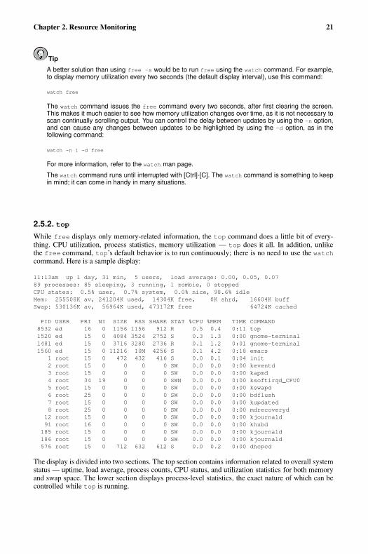
Chapter 2. Resource Monitoring 21
Tip
A better solution than using free -s would be to run free using the watch command. For example,to display memory utilization every two seconds (the default display interval), use this command:
watch free
The watch command issues the free command every two seconds, after first clearing the screen.This makes it much easier to see how memory utilization changes over time, as it is not necessary toscan continually scrolling output. You can control the delay between updates by using the -n option,and can cause any changes between updates to be highlighted by using the -d option, as in thefollowing command:
watch -n 1 -d free
For more information, refer to the watch man page.
The watch command runs until interrupted with [Ctrl]-[C]. The watch command is something to keepin mind; it can come in handy in many situations.
2.5.2. topWhile free displays only memory-related information, the top command does a little bit of every-thing. CPU utilization, process statistics, memory utilization — top does it all. In addition, unlikethe free command, top’s default behavior is to run continuously; there is no need to use the watchcommand. Here is a sample display:
11:13am up 1 day, 31 min, 5 users, load average: 0.00, 0.05, 0.0789 processes: 85 sleeping, 3 running, 1 zombie, 0 stoppedCPU states: 0.5% user, 0.7% system, 0.0% nice, 98.6% idleMem: 255508K av, 241204K used, 14304K free, 0K shrd, 16604K buffSwap: 530136K av, 56964K used, 473172K free 64724K cached
PID USER PRI NI SIZE RSS SHARE STAT %CPU %MEM TIME COMMAND8532 ed 16 0 1156 1156 912 R 0.5 0.4 0:11 top1520 ed 15 0 4084 3524 2752 S 0.3 1.3 0:00 gnome-terminal1481 ed 15 0 3716 3280 2736 R 0.1 1.2 0:01 gnome-terminal1560 ed 15 0 11216 10M 4256 S 0.1 4.2 0:18 emacs
1 root 15 0 472 432 416 S 0.0 0.1 0:04 init2 root 15 0 0 0 0 SW 0.0 0.0 0:00 keventd3 root 15 0 0 0 0 SW 0.0 0.0 0:00 kapmd4 root 34 19 0 0 0 SWN 0.0 0.0 0:00 ksoftirqd_CPU05 root 15 0 0 0 0 SW 0.0 0.0 0:00 kswapd6 root 25 0 0 0 0 SW 0.0 0.0 0:00 bdflush7 root 15 0 0 0 0 SW 0.0 0.0 0:00 kupdated8 root 25 0 0 0 0 SW 0.0 0.0 0:00 mdrecoveryd12 root 15 0 0 0 0 SW 0.0 0.0 0:00 kjournald91 root 16 0 0 0 0 SW 0.0 0.0 0:00 khubd
185 root 15 0 0 0 0 SW 0.0 0.0 0:00 kjournald186 root 15 0 0 0 0 SW 0.0 0.0 0:00 kjournald576 root 15 0 712 632 612 S 0.0 0.2 0:00 dhcpcd
The display is divided into two sections. The top section contains information related to overall systemstatus — uptime, load average, process counts, CPU status, and utilization statistics for both memoryand swap space. The lower section displays process-level statistics, the exact nature of which can becontrolled while top is running.
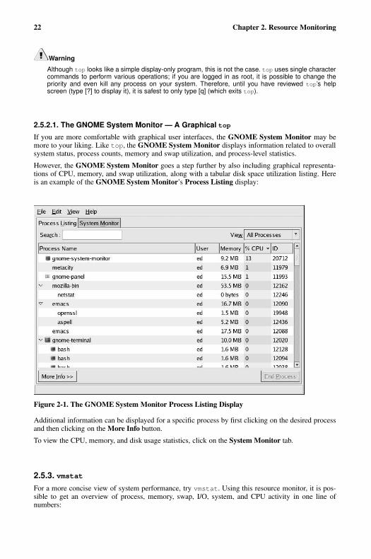
22 Chapter 2. Resource Monitoring
Warning
Although top looks like a simple display-only program, this is not the case. top uses single charactercommands to perform various operations; if you are logged in as root, it is possible to change thepriority and even kill any process on your system. Therefore, until you have reviewed top’s helpscreen (type [?] to display it), it is safest to only type [q] (which exits top).
2.5.2.1. The GNOME System Monitor — A Graphical top
If you are more comfortable with graphical user interfaces, the GNOME System Monitor may bemore to your liking. Like top, the GNOME System Monitor displays information related to overallsystem status, process counts, memory and swap utilization, and process-level statistics.
However, the GNOME System Monitor goes a step further by also including graphical representa-tions of CPU, memory, and swap utilization, along with a tabular disk space utilization listing. Hereis an example of the GNOME System Monitor’s Process Listing display:
Figure 2-1. The GNOME System Monitor Process Listing Display
Additional information can be displayed for a specific process by first clicking on the desired processand then clicking on the More Info button.
To view the CPU, memory, and disk usage statistics, click on the System Monitor tab.
2.5.3. vmstatFor a more concise view of system performance, try vmstat. Using this resource monitor, it is pos-sible to get an overview of process, memory, swap, I/O, system, and CPU activity in one line ofnumbers:
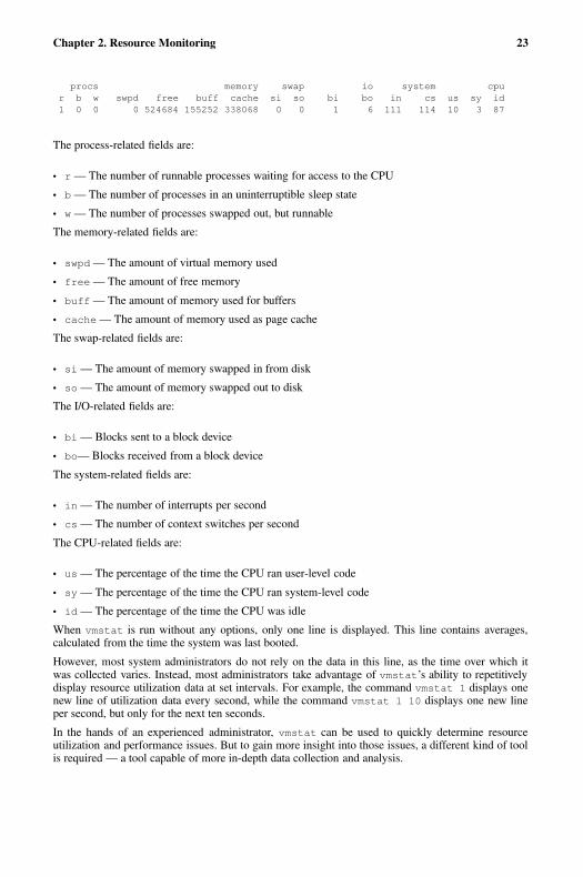
Chapter 2. Resource Monitoring 23
procs memory swap io system cpur b w swpd free buff cache si so bi bo in cs us sy id1 0 0 0 524684 155252 338068 0 0 1 6 111 114 10 3 87
The process-related fields are:
• r — The number of runnable processes waiting for access to the CPU
• b — The number of processes in an uninterruptible sleep state
• w — The number of processes swapped out, but runnable
The memory-related fields are:
• swpd — The amount of virtual memory used
• free — The amount of free memory
• buff — The amount of memory used for buffers
• cache — The amount of memory used as page cache
The swap-related fields are:
• si — The amount of memory swapped in from disk
• so — The amount of memory swapped out to disk
The I/O-related fields are:
• bi — Blocks sent to a block device
• bo— Blocks received from a block device
The system-related fields are:
• in — The number of interrupts per second
• cs — The number of context switches per second
The CPU-related fields are:
• us — The percentage of the time the CPU ran user-level code
• sy — The percentage of the time the CPU ran system-level code
• id — The percentage of the time the CPU was idle
When vmstat is run without any options, only one line is displayed. This line contains averages,calculated from the time the system was last booted.
However, most system administrators do not rely on the data in this line, as the time over which itwas collected varies. Instead, most administrators take advantage of vmstat’s ability to repetitivelydisplay resource utilization data at set intervals. For example, the command vmstat 1 displays onenew line of utilization data every second, while the command vmstat 1 10 displays one new lineper second, but only for the next ten seconds.
In the hands of an experienced administrator, vmstat can be used to quickly determine resourceutilization and performance issues. But to gain more insight into those issues, a different kind of toolis required — a tool capable of more in-depth data collection and analysis.
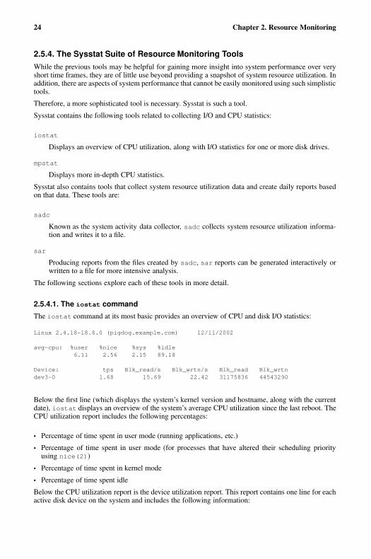
24 Chapter 2. Resource Monitoring
2.5.4. The Sysstat Suite of Resource Monitoring ToolsWhile the previous tools may be helpful for gaining more insight into system performance over veryshort time frames, they are of little use beyond providing a snapshot of system resource utilization. Inaddition, there are aspects of system performance that cannot be easily monitored using such simplistictools.
Therefore, a more sophisticated tool is necessary. Sysstat is such a tool.
Sysstat contains the following tools related to collecting I/O and CPU statistics:
iostat
Displays an overview of CPU utilization, along with I/O statistics for one or more disk drives.
mpstat
Displays more in-depth CPU statistics.
Sysstat also contains tools that collect system resource utilization data and create daily reports basedon that data. These tools are:
sadc
Known as the system activity data collector, sadc collects system resource utilization informa-tion and writes it to a file.
sar
Producing reports from the files created by sadc, sar reports can be generated interactively orwritten to a file for more intensive analysis.
The following sections explore each of these tools in more detail.
2.5.4.1. The iostat command
The iostat command at its most basic provides an overview of CPU and disk I/O statistics:
Linux 2.4.18-18.8.0 (pigdog.example.com) 12/11/2002
avg-cpu: %user %nice %sys %idle6.11 2.56 2.15 89.18
Device: tps Blk_read/s Blk_wrtn/s Blk_read Blk_wrtndev3-0 1.68 15.69 22.42 31175836 44543290
Below the first line (which displays the system’s kernel version and hostname, along with the currentdate), iostat displays an overview of the system’s average CPU utilization since the last reboot. TheCPU utilization report includes the following percentages:
• Percentage of time spent in user mode (running applications, etc.)
• Percentage of time spent in user mode (for processes that have altered their scheduling priorityusing nice(2))
• Percentage of time spent in kernel mode
• Percentage of time spent idle
Below the CPU utilization report is the device utilization report. This report contains one line for eachactive disk device on the system and includes the following information:

Chapter 2. Resource Monitoring 25
• The device specification, displayed as dev � major-number � -sequence-number, where� major-number � is the device’s major number3, and � sequence-number � is a sequencenumber starting at zero.
• The number of transfers (or I/O operations) per second.
• The number of 512-byte blocks read per second.
• The number of 512-byte blocks written per second.
• The total number of 512-byte blocks read.
• The total number of 512-byte block written.
This is just a sample of the information that can be obtained using iostat. For more information, seethe iostat(1) man page.
2.5.4.2. The mpstat command
The mpstat command at first appears no different from the CPU utilization report produced by io-stat:
Linux 2.4.18-14smp (pigdog.example.com) 12/11/2002
07:09:26 PM CPU %user %nice %system %idle intr/s07:09:26 PM all 6.40 5.84 3.29 84.47 542.47
With the exception of an additional column showing the interrupts per second being handled by theCPU, there is no real difference. However, the situation changes if mpstat’s -P ALL option is used:
Linux 2.4.18-14smp (pigdog.example.com) 12/11/2002
07:13:03 PM CPU %user %nice %system %idle intr/s07:13:03 PM all 6.40 5.84 3.29 84.47 542.4707:13:03 PM 0 6.36 5.80 3.29 84.54 542.4707:13:03 PM 1 6.43 5.87 3.29 84.40 542.47
On multiprocessor systems, mpstat allows the utilization for each CPU to be viewed individually,making it possible to determine how effectively each CPU is being used.
2.5.4.3. The sadc command
As stated earlier, the sadc command collects system utilization data and writes it to a file for lateranalysis. By default, the data is written to files in the /var/log/sa/ directory. The files are namedsa � dd � , where � dd � is the current day’s two-digit date.
sadc is normally run by the sa1 script. This script is periodically invoked by cron via the file sys-stat, which is located in /etc/crond.d. The sa1 script invokes sadc for a single one-secondmeasuring interval. By default, cron runs sa1 every 10 minutes, adding the data collected duringeach interval to the current /var/log/sa/sa � dd � file.
3. Device major numbers can be found by using ls -l to display the desired device file in /dev/. Here is
sample output from ls -l /dev/hda:
brw-rw---- 1 root disk 3, 0 Aug 30 19:31 /dev/hda
The major number in this example is 3, and appears between the file’s group and its minor number.
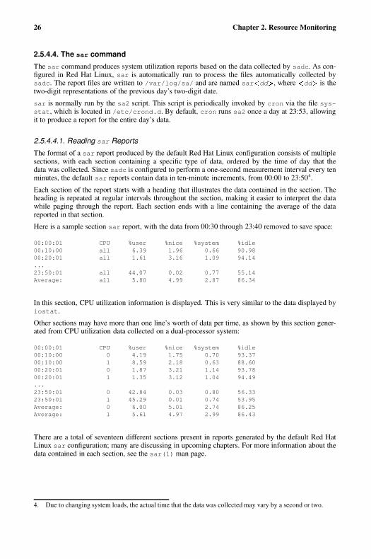
26 Chapter 2. Resource Monitoring
2.5.4.4. The sar command
The sar command produces system utilization reports based on the data collected by sadc. As con-figured in Red Hat Linux, sar is automatically run to process the files automatically collected bysadc. The report files are written to /var/log/sa/ and are named sar � dd , where � dd is thetwo-digit representations of the previous day’s two-digit date.
sar is normally run by the sa2 script. This script is periodically invoked by cron via the file sys-stat, which is located in /etc/crond.d. By default, cron runs sa2 once a day at 23:53, allowingit to produce a report for the entire day’s data.
2.5.4.4.1. Reading sar Reports
The format of a sar report produced by the default Red Hat Linux configuration consists of multiplesections, with each section containing a specific type of data, ordered by the time of day that thedata was collected. Since sadc is configured to perform a one-second measurement interval every tenminutes, the default sar reports contain data in ten-minute increments, from 00:00 to 23:504.
Each section of the report starts with a heading that illustrates the data contained in the section. Theheading is repeated at regular intervals throughout the section, making it easier to interpret the datawhile paging through the report. Each section ends with a line containing the average of the datareported in that section.
Here is a sample section sar report, with the data from 00:30 through 23:40 removed to save space:
00:00:01 CPU %user %nice %system %idle00:10:00 all 6.39 1.96 0.66 90.9800:20:01 all 1.61 3.16 1.09 94.14...23:50:01 all 44.07 0.02 0.77 55.14Average: all 5.80 4.99 2.87 86.34
In this section, CPU utilization information is displayed. This is very similar to the data displayed byiostat.
Other sections may have more than one line’s worth of data per time, as shown by this section gener-ated from CPU utilization data collected on a dual-processor system:
00:00:01 CPU %user %nice %system %idle00:10:00 0 4.19 1.75 0.70 93.3700:10:00 1 8.59 2.18 0.63 88.6000:20:01 0 1.87 3.21 1.14 93.7800:20:01 1 1.35 3.12 1.04 94.49...23:50:01 0 42.84 0.03 0.80 56.3323:50:01 1 45.29 0.01 0.74 53.95Average: 0 6.00 5.01 2.74 86.25Average: 1 5.61 4.97 2.99 86.43
There are a total of seventeen different sections present in reports generated by the default Red HatLinux sar configuration; many are discussing in upcoming chapters. For more information about thedata contained in each section, see the sar(1) man page.
4. Due to changing system loads, the actual time that the data was collected may vary by a second or two.
Chapter 2. Resource Monitoring 27
2.6. Additional ResourcesThis section includes various resources that can be used to learn more about resource monitoring andthe Red Hat Linux-specific subject matter discussed in this chapter.
2.6.1. Installed DocumentationThe following resources are installed in the course of a typical Red Hat Linux installation, and canhelp you learn more about the subject matter discussed in this chapter.
• free(1) man page — Displays free and used memory statistics.
• top(1) man page — Displays CPU utilization and process-level statistics.
• watch(1) man page — Periodically executes the specified program, displaying fullscreen output.
• GNOME System Monitor Help menu entry — Graphically displays process, CPU, memory, anddisk space utilization statistics.
• vmstat(8) man page — Displays a concise overview of process, memory, swap, I/O, system, andCPU utilization.
• iostat(1) man page — Displays CPU and I/O statistics.
• mpstat(1) man page — Displays individual CPU statistics on multiprocessor systems.
• sadc(8) man page — Collects system utilization data.
• sa1(8) man page — A script that runs sadc periodically.
• sar(1) man page — Produces system resource utilization reports.
• sa2(8) man page — Produces daily system resource utilization report files.
• nice(1) man page — Changes process scheduling priority.
2.6.2. Useful Websites
• http://linuxperf.nl.linux.org/ — The Linux Performance Tuning homepage. Provides a good in-troductory overview of resource monitoring for performance tuning purposes. The mailing list,unfortunately, appears to have been overrun by spam and is no longer used.
• http://people.redhat.com/alikins/system_tuning.html — System Tuning Info for Linux Servers. Astream-of-consciousness approach to performance tuning and resource monitoring for servers.
• http://www.linuxjournal.com/article.php?sid=2396 — Performance Monitoring Tools for Linux.This Linux Journal page is geared more toward the administrator interested in writing a customizedperformance graphing solution. Written several years ago, some of the details may no longer apply,but the overall concept and execution are sound.
2.6.3. Related BooksThe following books discuss various issues related to resource monitoring, and are good resources forRed Hat Linux system administrators:
• The Red Hat Linux Customization Guide; Red Hat, Inc. — Includes a chapter on many of theresource monitoring tools described here.

28 Chapter 2. Resource Monitoring
• Linux Performance Tuning and Capacity Planning by Jason R. Fink and Matthew D. Sherer; Sams— Provides more in-depth overviews of the resource monitoring tools presented here, and includesothers that might be appropriate for more specific resource monitoring needs.
• Red Hat Linux Security and Optimization by Mohammed J. Kabir; Red Hat Press — Approximatelythe first 150 pages of this book discuss performance-related issues. This includes chapters dedicatedto performance issues specific to network, Web, email, and file servers.
• Linux Administration Handbook by Evi Nemeth, Garth Snyder, and Trent R. Hein; Prentice Hall— Provides a short chapter similar in scope to this book, but includes an interesting section ondiagnosing a system that has suddenly slowed down.
• Linux System Administration: A User’s Guide by Marcel Gagne; Addison Wesley Professional —Contains a small chapter on performance monitoring and tuning.
Chapter 3.
Bandwidth and Processing Power
Of the two resources discussed in this chapter, one (bandwidth) is often hard for the new systemadministrator to understand, while the other (processing power) is usually a much easier concept tograsp.
Additionally, it may seem that these two resources are not that closely related — why group themtogether?
The reason for addressing both resources together is that these resources are based on the hardwarethat tie directly into a computer’s ability to move and process data. As such, their relationship is ofteninterrelated.
3.1. BandwidthAt its most basic, bandwidth is the capacity for data transfer — in other words, how much data can bemoved from one point to another in a given amount of time. Having point-to-point data communicationimplies two things:
• A set of electrical conductors used to make low-level communication possible
• A protocol to facilitate the efficient and reliable communication of data
There are two types of system components that meet these requirements:
• Buses
• Datapaths
The following sections explore each in more detail.
3.1.1. BusesAs stated above, buses enable point-to-point communication and use some sort of protocol to ensurethat all communication takes place in a controlled manner. However, buses have other distinguishingfeatures:
• Standardized electrical characteristics (such as the number of conductors, voltage levels, signalingspeeds, etc.)
• Standardized mechanical characteristics (such as the type of connector, card size, physical layout,etc.)
• Standardized protocol
The word "standardized" is important because buses are the primary way in which different systemcomponents are connected together.
In many cases, buses allow the interconnection of hardware that is made by multiple manufacturers;without standardization, this would not be possible. However, even in situations where a bus is pro-prietary to one manufacturer, standardization is important because it allows that manufacturer to moreeasily implement different components by using a common interface — the bus itself.
30 Chapter 3. Bandwidth and Processing Power
3.1.1.1. Examples of Buses
No matter where in a computer system you look, there are buses. Here are a few of the more commonones:
• Mass storage buses (IDE and SCSI)
• Networks1 (Ethernet and Token Ring)
• Memory buses (PC133 and Rambus)
• Expansion buses (PCI, ISA, USB)
3.1.2. DatapathsDatapaths can be harder to identify but, like buses, they are everywhere. Also like buses, datapathsenable point-to-point communication. However, unlike buses, datapaths:
• Use a simpler protocol (if any)
• Have little (if any) mechanical standardization
The reason for these differences is that datapaths are normally internal to some system componentand are not used to facilitate the ad-hoc interconnection of different components. As such, datapathsare highly optimized for a particular situation, where speed and low cost are preferred over slower andmore expensive general-purpose flexibility.
3.1.2.1. Examples of Datapaths
Here are some typical datapaths:
• CPU to on-chip cache datapath
• Graphics processor to video memory datapath
3.1.3. Potential Bandwidth-Related ProblemsThere are two ways in which bandwidth-related problems may occur (for either buses or datapaths):
1. The bus or datapath may represent a shared resource. In this situation, high levels of contentionfor the bus reduces the effective bandwidth available for all devices on the bus.
A SCSI bus with several highly-active disk drives would be a good example of this. The highly-active disk drives saturate the SCSI bus, leaving little bandwidth available for any other deviceon the same bus. The end result is that all I/O to any of the devices on this bus will be slow, evenif each device on the bus is not overly active.
2. The bus or datapath may be a dedicated resource with a fixed number of devices attached to it.In this case, the electrical characteristics of the bus (and to some extent the nature of the protocolbeing used) limit the available bandwidth. This is usually more the case with datapaths than withbuses. This is one reason why graphics adapters tend to perform more slowly when operating athigher resolutions and/or color depths — for every screen refresh, there is more data that mustbe passed along the datapath connecting video memory and the graphics processor.
1. Instead of an intra-system bus, networks can be thought of as an inter-system bus.
Chapter 3. Bandwidth and Processing Power 31
3.1.4. Potential Bandwidth-related SolutionsFortunately, bandwidth-related problems can be addressed. In fact, there are several approaches youcan take:
• Spread the load
• Reduce the load
• Increase the capacity
The following sections explore each approach in more detail.
3.1.4.1. Spread the Load
Another approach is to more evenly distribute the bus activity. In other words, if one bus is overloadedand another is idle, perhaps the situation would be improved by moving some of the load to the idlebus.
As a system administrator, this is the first approach you should consider, as often there are additionalbuses already present in your system. For example, most PCs include at least two IDE channels (whichis just another name for a bus). If you have two IDE disk drives and two IDE channels, why shouldboth drives be on the same channel?
Even if your system configuration does not include additional buses, spreading the load might still bea reasonable approach. The hardware expenditures to do so would be less expensive than replacing anexisting bus with higher-capacity hardware.
3.1.4.2. Reduce the Load
At first glance, reducing the load and spreading the load appear to be different sides of the same coin.After all, when one spreads the load, it acts to reduce the load (at least on the overloaded bus), correct?
While this viewpoint is correct, it is not the same as reducing the load globally. The key here is to de-termine if there is some aspect of the system load that is causing this particular bus to be overloaded.For example, is a network heavily loaded due to activities that are unnecessary? Perhaps a small tem-porary file is the recipient of heavy read/write I/O. If that temporary file was created on a networkedfile server, a great deal of network traffic could be eliminated by working with the file locally.
3.1.4.3. Increase the Capacity
The obvious solution to insufficient bandwidth is to increase it somehow. However, this is usuallyan expensive proposition. Consider, for example, a SCSI controller and its overloaded bus. In orderto increase its bandwidth, the SCSI controller (and likely all devices attached to it) would need tobe replaced with faster hardware. If the SCSI controller is a separate card, this would be a relativelystraightforward process, but if the SCSI controller is part of the system’s motherboard, it becomesmuch more difficult to justify the economics of such a change.
3.1.5. In Summary. . .All system administrators should be aware of bandwidth, and how system configuration and usageimpacts available bandwidth. Unfortunately, it is not always apparent what is a bandwidth-relatedproblem and what is not. Sometimes, the problem is not the bus itself, but one of the componentsattached to the bus.

32 Chapter 3. Bandwidth and Processing Power
For example, consider a SCSI adapter that is connected to a PCI bus. If there are performance problemswith SCSI disk I/O, it might be the result of a poorly-performing SCSI adapter, even though the SCSIand PCI buses themselves are nowhere near their bandwidth capabilities.
3.2. Processing PowerOften known as CPU power, CPU cycles, and various other names, processing power is the abilityof a computer to manipulate data. Processing power varies with the architecture (and clock speed) ofthe CPU — usually CPUs with higher clock speeds and those supporting larger word sizes have moreprocessing power than slower CPUs supporting smaller word sizes.
3.2.1. Facts About Processing PowerHere are the two main facts about processing power that you should keep in mind:
• Processing power is fixed
• Processing power cannot be stored
Processing power is fixed, in that the CPU can only go so fast. For example, if you need to addtwo numbers together (an operation that takes only one machine instruction on most architectures), aparticular CPU can do it at one speed, and one speed only. With few exceptions, it is not even possibleto slow the rate at which a CPU processes instructions.
Processing power is also fixed in another way: it is finite. That is, there are limits to the CPU perfor-mance you can put into any given computer. Some systems are capable of supporting a wide range ofCPU speeds, while others may not be upgradeable at all2.
Processing power cannot be stored for later use. In other words, if a CPU can process 100 millioninstructions in one second, one second of idle time equals 100 million instructions that have beenwasted.
If we take these facts and look at them from a slightly different perspective, a CPU "produces" astream of executed instructions at a fixed rate. And if the CPU "produces" executed instructions, thatmeans that something else must "consume" them. The next section describes what these consumersare.
3.2.2. Consumers of Processing PowerThere are two main consumers of processing power:
• Applications
• The operating system itself
3.2.2.1. Applications
The most obvious consumers of processing power are the applications and programs you want thecomputer to run for you. From a spreadsheet to a database, these are the reasons you have a computer.
A single-CPU system can only do one thing at any given time. Therefore, if your application is run-ning, everything else on the system is not. And the opposite is, of course, true — if something otherthan your application is running, then your application is doing nothing.
2. This situation leads to what is humorously termed as a forklift upgrade, which means a complete replacement
of a computer.
Chapter 3. Bandwidth and Processing Power 33
But how is it that many different applications can seemingly run at once under Red Hat Linux? Theanswer is that Red Hat Linux is a multitasking operating system. In other words, it creates the illusionthat many different things are going on simultaneously when in fact that is not possible. The trick isto give each process a fraction of a second’s worth of time running on the CPU before giving the CPUto another process for another fraction of a second. If these context switches happen quickly enough,the illusion of multiple applications running simultaneously is achieved.
Of course, applications do other things than manipulate data using the CPU. They may wait for userinput as well as performing I/O to devices such as disk drives and graphics displays. When theseevents take place, the application does not need the CPU. At these times, the CPU can be used forother processes running other applications without slowing the waiting application at all.
In addition, the CPU can be used by another consumer of processing power: the operating systemitself.
3.2.2.2. The Operating System
It is difficult to determine how much processing power is consumed by the operating system. Thereason for this is that operating systems use a mixture of process-level and system-level code toperform their work. While, for example, it is easy to use top to see what the process running thesystem logging daemon syslogd is doing, it is not so easy to see how much processing power isbeing consumed by system-level I/O-related processing.
In general, it is possible to divide this kind of operating system overhead into two types:
• Operating system housekeeping
• Process-related activities
Operating system housekeeping includes activities such as process scheduling and memory manage-ment, while process-related activities include any processes that support the operating system itself(including system daemons such as syslogd, klogd, etc.).
3.2.3. Improving a CPU ShortageWhen there is insufficient processing power available for the work that needs to be done, you havetwo options:
• Reducing the load
• Increasing the capacity
3.2.3.1. Reducing the Load
Reducing the CPU load is something that can be done with no expenditure of money. The trick is toidentify those aspects of the system load that are under your control and can be cut back. There arethree areas to focus on:
• Reducing operating system overhead
• Reducing application overhead
• Eliminating applications entirely
34 Chapter 3. Bandwidth and Processing Power
3.2.3.1.1. Reducing Operating System Overhead
In order to reduce operating system overhead, you must look at your current system load and deter-mine what aspects of it result in inordinate amounts of overhead. These areas could include:
• Reducing the need for frequent process scheduling
• Lowering the amount of I/O performed
Do not expect miracles; in a reasonably-well configured system, it is unlikely that you will see muchof a performance increase by trying to reduce operating system overhead. This is due to the factthat a reasonably-well configured system will, by definition, result in a minimal amount of overhead.However, if your system is running with too little RAM for instance, you may be able to reduceoverhead by alleviating the RAM shortage.
3.2.3.1.2. Reducing Application Overhead
Reducing application overhead means making sure that the application has everything it needs torun well. Some applications exhibit wildly different behaviors under different environments — anapplication may become highly compute-bound while processing certain types of data, but not others.
The point to keep in mind here is that you must understand the applications running on your systemif you are to enable them to run as efficiently as possible. Often this entails working with your users,and/or your organization’s developers, to help uncover ways in which the applications can be made torun more efficiently.
3.2.3.1.3. Eliminating Applications Entirely
Depending on your organization, this approach might not be available to you, as it often is not asystem administrator’s responsibility to dictate which applications will and will not be run. However,if you can identify any applications that are known "CPU hogs", you might be able to influence thepowers-that-be to retire them.
Doing this will likely involve more than just yourself. The affected users should certainly be a partof this process; in many cases they may have the knowledge and the political power to make thenecessary changes to the application lineup.
Tip
Keep in mind that an application may not need to be eliminated from every system in your organiza-tion. You might be able to move a particularly CPU-hungry application from an overloaded system toanother system that is nearly idle.
3.2.3.2. Increasing the Capacity
Of course, if it is not possible to reduce the demand for processing power, you must find ways ofincreasing the processing power that is available. To do so costs money, but it can be done.
Chapter 3. Bandwidth and Processing Power 35
3.2.3.2.1. Upgrading the CPU
The most straightforward approach is to determine if your system’s CPU can be upgraded. The firststep is to see if the current CPU can be removed. Some systems (primarily laptops) have CPUs thatare soldered in place, making an upgrade impossible. The rest, however, have socketed CPUs, makingupgrades possible — at least in theory.
Next, you must do some research to determine if a faster CPU exists for your system configuration.For example, if you currently have a 1GHz CPU, and a 2GHz unit of the same type exists, an upgrademight be possible.
Finally, you must determine the maximum clock speed supported by your system. To continue theexample above, even if a 2GHz CPU of the proper type exists, a simple CPU swap is not an option ifyour system only supports processors running at 1GHz or below.
Should you find that you cannot install a faster CPU in your system, your options may be limited tochanging motherboards or even the more expensive forklift upgrade mentioned earlier.
However, some system configurations make a slightly different approach possible. Instead of replacingthe current CPU, why not just add another one?
3.2.3.2.2. Is Symmetric Multiprocessing Right for You?
Symmetric multiprocessing (also known as SMP) makes it possible for a computer system to havemore than one CPU sharing all system resources. This means that, unlike a uniprocessor system, anSMP system may actually have more than one process running at the same time.
At first glance, this seems like any system administrator’s dream. First and foremost, SMP makes itpossible to increase a system’s CPU power even if CPUs with faster clock speeds are not available —just by adding another CPU. However, this flexibility comes with some caveats.
The first caveat is that not all systems are capable of SMP operation. Your system must have a moth-erboard designed to support multiple processors. If it does not, a motherboard upgrade (at the least)would be required.
The second caveat is that SMP increases system overhead. This makes sense if you stop to thinkabout it; with more CPUs to schedule work for, the operating system requires more CPU cycles foroverhead. Another aspect to this is that with multiple CPUs there can be more contention for systemresources. Because of these factors, upgrading a dual-processor system to a quad-processor unit doesnot result in a 100% increase in available CPU power. In fact, depending on the actual hardware, theworkload, and the processor architecture, it is possible to reach a point where the addition of anotherprocessor could actually reduce system performance.
Another point to keep in mind is that SMP does not help workloads that consist of one monolithicapplication with a single stream of execution. In other words, if a large compute-bound simulationprogram runs as one process and with no threads, it will not run any faster on an SMP system than ona single-processor machine. In fact, it may even run somewhat slower, due to the increased overheadSMP brings. For these reasons, many system administrators feel that when it comes to CPU power,single stream processing power is the way to go. It provides the most CPU power with the fewestrestrictions on its use.
While this discussion seems to indicate that SMP is never a good idea, there are circumstances inwhich it makes sense. For example, environments running multiple highly compute-bound applica-tions are good candidates for SMP. The reason for this is that applications that do nothing but computefor long periods of time keep contention between active processes (and therefore, the operating systemoverhead) to a minimum, while the processes themselves keep every CPU busy.
One other thing to keep in mind about SMP is that the performance of an SMP system tends todegrade more gracefully as the system load increases. This does make SMP systems popular in serverand multi-user environments, as the ever-changing process mix impacts the system-wide load less ona multi-processor machine.
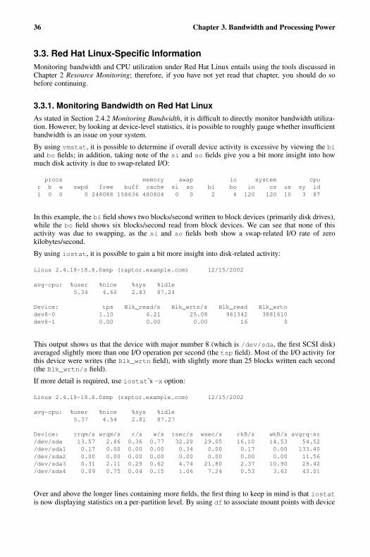
36 Chapter 3. Bandwidth and Processing Power
3.3. Red Hat Linux-Specific InformationMonitoring bandwidth and CPU utilization under Red Hat Linux entails using the tools discussed inChapter 2 Resource Monitoring; therefore, if you have not yet read that chapter, you should do sobefore continuing.
3.3.1. Monitoring Bandwidth on Red Hat LinuxAs stated in Section 2.4.2 Monitoring Bandwidth, it is difficult to directly monitor bandwidth utiliza-tion. However, by looking at device-level statistics, it is possible to roughly gauge whether insufficientbandwidth is an issue on your system.
By using vmstat, it is possible to determine if overall device activity is excessive by viewing the biand bo fields; in addition, taking note of the si and so fields give you a bit more insight into howmuch disk activity is due to swap-related I/O:
procs memory swap io system cpur b w swpd free buff cache si so bi bo in cs us sy id1 0 0 0 248088 158636 480804 0 0 2 6 120 120 10 3 87
In this example, the bi field shows two blocks/second written to block devices (primarily disk drives),while the bo field shows six blocks/second read from block devices. We can see that none of thisactivity was due to swapping, as the si and so fields both show a swap-related I/O rate of zerokilobytes/second.
By using iostat, it is possible to gain a bit more insight into disk-related activity:
Linux 2.4.18-18.8.0smp (raptor.example.com) 12/15/2002
avg-cpu: %user %nice %sys %idle5.34 4.60 2.83 87.24
Device: tps Blk_read/s Blk_wrtn/s Blk_read Blk_wrtndev8-0 1.10 6.21 25.08 961342 3881610dev8-1 0.00 0.00 0.00 16 0
This output shows us that the device with major number 8 (which is /dev/sda, the first SCSI disk)averaged slightly more than one I/O operation per second (the tsp field). Most of the I/O activity forthis device were writes (the Blk_wrtn field), with slightly more than 25 blocks written each second(the Blk_wrtn/s field).
If more detail is required, use iostat’s -x option:
Linux 2.4.18-18.8.0smp (raptor.example.com) 12/15/2002
avg-cpu: %user %nice %sys %idle5.37 4.54 2.81 87.27
Device: rrqm/s wrqm/s r/s w/s rsec/s wsec/s rkB/s wkB/s avgrq-sz/dev/sda 13.57 2.86 0.36 0.77 32.20 29.05 16.10 14.53 54.52/dev/sda1 0.17 0.00 0.00 0.00 0.34 0.00 0.17 0.00 133.40/dev/sda2 0.00 0.00 0.00 0.00 0.00 0.00 0.00 0.00 11.56/dev/sda3 0.31 2.11 0.29 0.62 4.74 21.80 2.37 10.90 29.42/dev/sda4 0.09 0.75 0.04 0.15 1.06 7.24 0.53 3.62 43.01
Over and above the longer lines containing more fields, the first thing to keep in mind is that iostatis now displaying statistics on a per-partition level. By using df to associate mount points with device
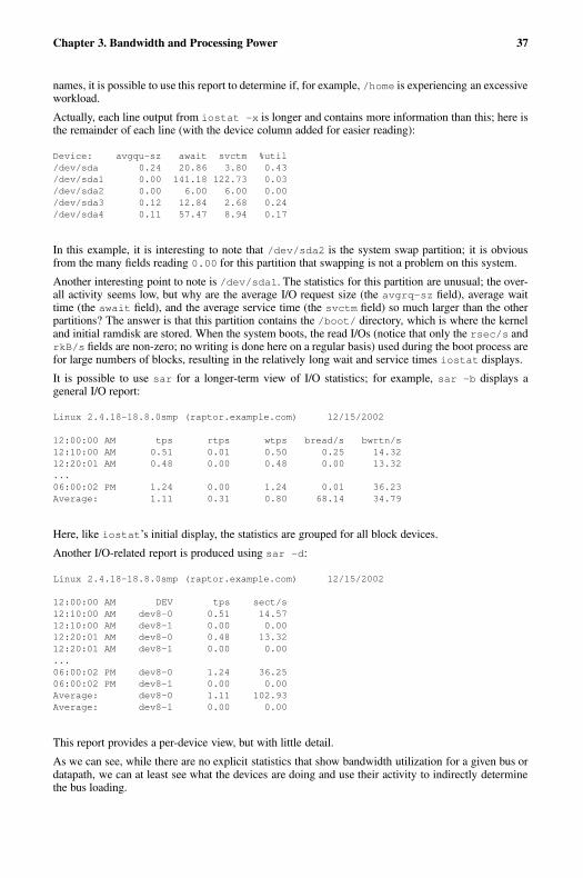
Chapter 3. Bandwidth and Processing Power 37
names, it is possible to use this report to determine if, for example, /home is experiencing an excessiveworkload.
Actually, each line output from iostat -x is longer and contains more information than this; here isthe remainder of each line (with the device column added for easier reading):
Device: avgqu-sz await svctm %util/dev/sda 0.24 20.86 3.80 0.43/dev/sda1 0.00 141.18 122.73 0.03/dev/sda2 0.00 6.00 6.00 0.00/dev/sda3 0.12 12.84 2.68 0.24/dev/sda4 0.11 57.47 8.94 0.17
In this example, it is interesting to note that /dev/sda2 is the system swap partition; it is obviousfrom the many fields reading 0.00 for this partition that swapping is not a problem on this system.
Another interesting point to note is /dev/sda1. The statistics for this partition are unusual; the over-all activity seems low, but why are the average I/O request size (the avgrq-sz field), average waittime (the await field), and the average service time (the svctm field) so much larger than the otherpartitions? The answer is that this partition contains the /boot/ directory, which is where the kerneland initial ramdisk are stored. When the system boots, the read I/Os (notice that only the rsec/s andrkB/s fields are non-zero; no writing is done here on a regular basis) used during the boot process arefor large numbers of blocks, resulting in the relatively long wait and service times iostat displays.
It is possible to use sar for a longer-term view of I/O statistics; for example, sar -b displays ageneral I/O report:
Linux 2.4.18-18.8.0smp (raptor.example.com) 12/15/2002
12:00:00 AM tps rtps wtps bread/s bwrtn/s12:10:00 AM 0.51 0.01 0.50 0.25 14.3212:20:01 AM 0.48 0.00 0.48 0.00 13.32...06:00:02 PM 1.24 0.00 1.24 0.01 36.23Average: 1.11 0.31 0.80 68.14 34.79
Here, like iostat’s initial display, the statistics are grouped for all block devices.
Another I/O-related report is produced using sar -d:
Linux 2.4.18-18.8.0smp (raptor.example.com) 12/15/2002
12:00:00 AM DEV tps sect/s12:10:00 AM dev8-0 0.51 14.5712:10:00 AM dev8-1 0.00 0.0012:20:01 AM dev8-0 0.48 13.3212:20:01 AM dev8-1 0.00 0.00...06:00:02 PM dev8-0 1.24 36.2506:00:02 PM dev8-1 0.00 0.00Average: dev8-0 1.11 102.93Average: dev8-1 0.00 0.00
This report provides a per-device view, but with little detail.
As we can see, while there are no explicit statistics that show bandwidth utilization for a given bus ordatapath, we can at least see what the devices are doing and use their activity to indirectly determinethe bus loading.
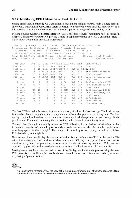
38 Chapter 3. Bandwidth and Processing Power
3.3.2. Monitoring CPU Utilization on Red Hat LinuxUnlike bandwidth, monitoring CPU utilization is much more straightforward. From a single percent-age of CPU utilization in GNOME System Monitor, to the more in-depth statistics reported by sar,it is possible to accurately determine how much CPU power is being consumed and by what.
Moving beyond GNOME System Monitor, top is the first resource monitoring tool discussed inChapter 2 Resource Monitoring to provide a more in-depth representation of CPU utilization. Here isa top report from a dual-processor workstation:
9:44pm up 2 days, 2 min, 1 user, load average: 0.14, 0.12, 0.0990 processes: 82 sleeping, 1 running, 7 zombie, 0 stoppedCPU0 states: 0.4% user, 1.1% system, 0.0% nice, 97.4% idleCPU1 states: 0.5% user, 1.3% system, 0.0% nice, 97.1% idleMem: 1288720K av, 1056260K used, 232460K free, 0K shrd, 145644K buffSwap: 522104K av, 0K used, 522104K free 469764K cached
PID USER PRI NI SIZE RSS SHARE STAT %CPU %MEM TIME COMMAND30997 ed 16 0 1100 1100 840 R 1.7 0.0 0:00 top1120 root 5 -10 249M 174M 71508 S < 0.9 13.8 254:59 X1260 ed 15 0 54408 53M 6864 S 0.7 4.2 12:09 gnome-terminal888 root 15 0 2428 2428 1796 S 0.1 0.1 0:06 sendmail1264 ed 15 0 16336 15M 9480 S 0.1 1.2 1:58 rhn-applet-gui
1 root 15 0 476 476 424 S 0.0 0.0 0:05 init2 root 0K 0 0 0 0 SW 0.0 0.0 0:00 migration_CPU03 root 0K 0 0 0 0 SW 0.0 0.0 0:00 migration_CPU14 root 15 0 0 0 0 SW 0.0 0.0 0:01 keventd5 root 34 19 0 0 0 SWN 0.0 0.0 0:00 ksoftirqd_CPU06 root 34 19 0 0 0 SWN 0.0 0.0 0:00 ksoftirqd_CPU17 root 15 0 0 0 0 SW 0.0 0.0 0:05 kswapd8 root 15 0 0 0 0 SW 0.0 0.0 0:00 bdflush9 root 15 0 0 0 0 SW 0.0 0.0 0:01 kupdated10 root 25 0 0 0 0 SW 0.0 0.0 0:00 mdrecoveryd
The first CPU-related information is present on the very first line: the load average. The load averageis a number that corresponds to the average number of runnable processes on the system. The loadaverage is often listed as three sets of numbers (as seen here), which represent the load average for thepast 1, 5, and 15 minutes, indicating that the system in this example was not very busy.
The next line, although not strictly related to CPU utilization, has an indirect relationship, in thatit shows the number of runnable processes (here, only one -- remember this number, as it meanssomething special in this example). The number of runnable processes is a good indicator of howCPU-bound a system might be.
Next are two lines that display the current utilization for each of the two CPUs in the system. Theutilization statistics are broken down to show whether the CPU cycles expended were done so foruser-level or system-level processing; also included is a statistic showing how much CPU time wasexpended by processes with altered scheduling priorities. Finally, there is an idle time statistic.
Moving down into the process-related section of the display, we find that the process using the mostCPU power is top itself; in other words, the one runnable process on this otherwise-idle system wastop taking a "picture" of itself.
Tip
It is important to remember that the very act of running a system monitor affects the resource utiliza-tion statistics you receive. All software-based monitors do this to some extent.
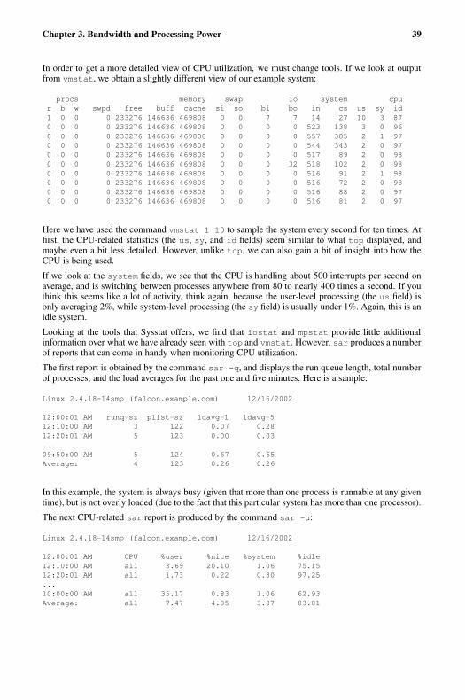
Chapter 3. Bandwidth and Processing Power 39
In order to get a more detailed view of CPU utilization, we must change tools. If we look at outputfrom vmstat, we obtain a slightly different view of our example system:
procs memory swap io system cpur b w swpd free buff cache si so bi bo in cs us sy id1 0 0 0 233276 146636 469808 0 0 7 7 14 27 10 3 870 0 0 0 233276 146636 469808 0 0 0 0 523 138 3 0 960 0 0 0 233276 146636 469808 0 0 0 0 557 385 2 1 970 0 0 0 233276 146636 469808 0 0 0 0 544 343 2 0 970 0 0 0 233276 146636 469808 0 0 0 0 517 89 2 0 980 0 0 0 233276 146636 469808 0 0 0 32 518 102 2 0 980 0 0 0 233276 146636 469808 0 0 0 0 516 91 2 1 980 0 0 0 233276 146636 469808 0 0 0 0 516 72 2 0 980 0 0 0 233276 146636 469808 0 0 0 0 516 88 2 0 970 0 0 0 233276 146636 469808 0 0 0 0 516 81 2 0 97
Here we have used the command vmstat 1 10 to sample the system every second for ten times. Atfirst, the CPU-related statistics (the us, sy, and id fields) seem similar to what top displayed, andmaybe even a bit less detailed. However, unlike top, we can also gain a bit of insight into how theCPU is being used.
If we look at the system fields, we see that the CPU is handling about 500 interrupts per second onaverage, and is switching between processes anywhere from 80 to nearly 400 times a second. If youthink this seems like a lot of activity, think again, because the user-level processing (the us field) isonly averaging 2%, while system-level processing (the sy field) is usually under 1%. Again, this is anidle system.
Looking at the tools that Sysstat offers, we find that iostat and mpstat provide little additionalinformation over what we have already seen with top and vmstat. However, sar produces a numberof reports that can come in handy when monitoring CPU utilization.
The first report is obtained by the command sar -q, and displays the run queue length, total numberof processes, and the load averages for the past one and five minutes. Here is a sample:
Linux 2.4.18-14smp (falcon.example.com) 12/16/2002
12:00:01 AM runq-sz plist-sz ldavg-1 ldavg-512:10:00 AM 3 122 0.07 0.2812:20:01 AM 5 123 0.00 0.03...09:50:00 AM 5 124 0.67 0.65Average: 4 123 0.26 0.26
In this example, the system is always busy (given that more than one process is runnable at any giventime), but is not overly loaded (due to the fact that this particular system has more than one processor).
The next CPU-related sar report is produced by the command sar -u:
Linux 2.4.18-14smp (falcon.example.com) 12/16/2002
12:00:01 AM CPU %user %nice %system %idle12:10:00 AM all 3.69 20.10 1.06 75.1512:20:01 AM all 1.73 0.22 0.80 97.25...10:00:00 AM all 35.17 0.83 1.06 62.93Average: all 7.47 4.85 3.87 83.81

40 Chapter 3. Bandwidth and Processing Power
The statistics contained in this report are no different from those produced by many of the other tools.The biggest benefit here is that sar makes the data available on an ongoing basis and is thereforemore useful for obtaining long-term averages, or for the production of CPU utilization graphs.
On multiprocessor systems, the sar -U command can produce statistics for an individual processoror for all processors. Here is an example of output from sar -U ALL:
Linux 2.4.18-14smp (falcon.example.com) 12/16/2002
12:00:01 AM CPU %user %nice %system %idle12:10:00 AM 0 3.46 21.47 1.09 73.9812:10:00 AM 1 3.91 18.73 1.03 76.3312:20:01 AM 0 1.63 0.25 0.78 97.3412:20:01 AM 1 1.82 0.20 0.81 97.17...10:00:00 AM 0 39.12 0.75 1.04 59.0910:00:00 AM 1 31.22 0.92 1.09 66.77Average: 0 7.61 4.91 3.86 83.61Average: 1 7.33 4.78 3.88 84.02
The sar -w command reports on the number of context switches per second, making it possible togain additional insight in where CPU cycles are being spent:
Linux 2.4.18-14smp (falcon.example.com) 12/16/2002
12:00:01 AM cswch/s12:10:00 AM 537.9712:20:01 AM 339.43...10:10:00 AM 319.42Average: 1158.25
It is also possible to produce two different sar reports on interrupt activity. The first, (produced usingthe sar -I SUM command) displays a single "interrupts per second" statistic:
Linux 2.4.18-14smp (falcon.example.com) 12/16/2002
12:00:01 AM INTR intr/s12:10:00 AM sum 539.1512:20:01 AM sum 539.49...10:40:01 AM sum 539.10Average: sum 541.00
By using the command sar -I PROC, it is possible to break down interrupt activity by processor (onmultiprocessor systems) and by interrupt level (from 0 to 15):
Linux 2.4.18-18.8.0 (pigdog.example.com) 12/16/2002
12:00:00 AM CPU i000/s i001/s i002/s i008/s i009/s i011/s i012/s12:10:01 AM 0 512.01 0.00 0.00 0.00 3.44 0.00 0.00
12:10:01 AM CPU i000/s i001/s i002/s i008/s i009/s i011/s i012/s12:20:01 AM 0 512.00 0.00 0.00 0.00 3.73 0.00 0.00...10:30:01 AM CPU i000/s i001/s i002/s i003/s i008/s i009/s i010/s10:40:02 AM 0 512.00 1.67 0.00 0.00 0.00 15.08 0.00Average: 0 512.00 0.42 0.00 N/A 0.00 6.03 N/A
Chapter 3. Bandwidth and Processing Power 41
This report (which has been truncated horizontally to fit on the page) includes one column for eachinterrupt level (the i002/s field illustrating the rate for interrupt level 2). If this were a multiprocessorsystem, there would be one line per sample period for each CPU.
Another important point to note about this report is that sar adds or removes specific interrupt fieldsif no data is collected for that field. This can be seen in the example report above; the end of the reportincludes interrupt levels (3 and 10) that were not present at the start of the sampling period.
Note
There are two other interrupt-related sar reports — sar -I ALL and sar -I XALL. However, thedefault configuration for the sadc data collection utility does not collect the information necessary forthese reports. This can be changed by editing the file /etc/cron.d/sysstat, and changing this line:
*/10 * * * * root /usr/lib/sa/sa1 1 1
to look like this:
*/10 * * * * root /usr/lib/sa/sa1 -I 1 1
Keep in mind that this change does cause additional information to be collected by sadc, and resultsin larger data file sizes. Therefore, make sure your system configuration can support the additionalspace consumption.
3.4. Additional ResourcesThis section includes various resources that can be used to learn more about the Red Hat Linux-specific subject matter discussed in this chapter.
3.4.1. Installed DocumentationThe following resources are installed in the course of a typical Red Hat Linux installation and canhelp you learn more about the subject matter discussed in this chapter.
• vmstat(8) man page — Displays a concise overview of process, memory, swap, I/O, system, andCPU utilization.
• iostat(1) man page — Displays CPU and I/O statistics.
• sar(1) man page — Produces system resource utilization reports.
• sadc(8) man page — Collects system utilization data.
• sa1(8) man page — A script that runs sadc periodically.
• top(1) man page — Displays CPU utilization and process-level statistics.
42 Chapter 3. Bandwidth and Processing Power
3.4.2. Useful Websites
• http://linuxperf.nl.linux.org/ — The Linux Performance Tuning homepage. Provides a good in-troductory overview of resource monitoring for performance tuning purposes. The mailing list,unfortunately, appears to have been overrun by spam and is no longer used.
• http://people.redhat.com/alikins/system_tuning.html — System Tuning Info for Linux Servers. Astream-of-consciousness approach to performance tuning and resource monitoring for servers.
• http://www.linuxjournal.com/article.php?sid=2396 — Performance Monitoring Tools for Linux.This Linux Journal page is geared more toward the administrator interested in writing a customizedperformance graphing solution. Written several years ago, some of the details may no longer apply,but the overall concept and execution are sound.
3.4.3. Related BooksThe following books discuss various issues related to resource monitoring, and are good resources forRed Hat Linux system administrators:
• The Red Hat Linux Customization Guide; Red Hat, Inc. — Includes a chapter on many of theresource monitoring tools described here.
• Linux Performance Tuning and Capacity Planning by Jason R. Fink and Matthew D. Sherer; Sams— Provides more in-depth overviews of the resource monitoring tools presented here, and includesothers that might be appropriate for more specific resource monitoring needs.
• Linux Administration Handbook by Evi Nemeth, Garth Snyder, and Trent R. Hein; Prentice Hall— Provides a short chapter similar in scope to this book, but includes an interesting section ondiagnosing a system that has suddenly slowed down.
• Linux System Administration: A User’s Guide by Marcel Gagne; Addison Wesley Professional —Contains a small chapter on performance monitoring and tuning.
Chapter 4.
Physical and Virtual Memory
All present-day, general-purpose computers are of the type known as stored program computers. Asthe name implies, stored program computers can load instructions (the building blocks of programs)into some type of internal storage and can subsequently execute those instructions.
Stored program computers also use the same storage for data. This is in contrast to computers that usetheir hardware configuration to control their operation (such as older plugboard-based computers).
The place where programs were stored on the first stored program computers went by a variety ofnames and used a variety of different technologies, from spots on a cathode ray tube, to pressurepulses in columns of mercury. Fortunately, present-day computers use technologies with greater stor-age capacity and much smaller size than ever before.
4.1. Storage Access PatternsOne thing to keep in mind throughout this chapter is that computers tend to access storage in certainways. In fact, most storage access tends to exhibit one (or both) of the following attributes:
• Access tends to be sequential
• Access tends to be localized
Let us look at these points in a bit more detail.
Sequential access means that, if address N is accessed by the CPU, it is highly likely that address N+1will be accessed next. This makes sense, as most programs consist of large sections of instructionsthat execute one after the other.
Localized access means that, if address X is accessed, it is likely that other addresses surrounding Xwill also be accessed in the future.
These attributes are crucial, because it allows smaller, faster storage to effectively buffer larger, slowerstorage. This is the basis for implementing virtual memory. But before we can discuss virtual memory,we must look at the various storage technologies currently in use.
4.2. The Storage SpectrumPresent-day computers actually use a variety of storage technologies. Each technology is geared to-ward a specific function, with speeds and capacities to match. These technologies are:
• CPU registers
• Cache memory
• RAM
• Hard drives
• Off-line backup storage (tape, optical disk, etc.)
In terms of capabilities and cost, these technologies form a spectrum. For example, CPU registers are:
• Very fast (access times of a few nanoseconds)
• Low capacity (usually less than 200 bytes)
44 Chapter 4. Physical and Virtual Memory
• Very limited expansion capabilities (a change in CPU architecture would be required)
• Expensive (more than one dollar/byte)
However, at the other end of the spectrum, off-line backup storage is:
• Very slow (access times may be measured in days, if the backup media must be shipped longdistances)
• Very high capacity (10s - 100s of gigabytes)
• Essentially unlimited expansion capabilities (limited only by the floorspace needed to house thebackup media)
• Very inexpensive (fractional cents/byte)
By using different technologies with different capabilities, it is possible to fine-tune system design formaximum performance at the lowest possible cost. The following sections explore each technology inthe spectrum.
4.2.1. CPU RegistersEvery present-day CPU design includes registers for a variety of purposes, from storing the addressof the currently-executed instruction to more general-purpose data storage and manipulation. CPUregisters run at the same speed as the rest of the CPU; otherwise, they would be a serious bottleneckto overall system performance. The reason for this is that nearly all operations performed by the CPUinvolve the registers in one way or another.
The number of CPU registers (and their uses) are strictly dependent on the architectural design of theCPU itself. There is no way to change the number of CPU registers, short of migrating to a CPU witha different architecture. For these reasons, the number of CPU registers can be considered a constant,as they are unchangeable without great pain.
4.2.2. Cache MemoryThe purpose of cache memory is to act as a buffer between the very limited, very high-speed CPUregisters and the relatively slower and much larger main system memory — usually referred to asRAM1. Cache memory has an operating speed similar to the CPU itself, so that when the CPU accessesdata in cache, the CPU is not kept waiting for the data.
Cache memory is configured such that, whenever data is to be read from RAM, the system hardwarefirst checks to see if the desired data is in cache. If the data is in cache, it is quickly retrieved, andused by the CPU. However, if the data is not in cache, the data is read from RAM and, while beingtransferred to the CPU, is also placed in cache (in case it will be needed again). From the perspectiveof the CPU, all this is done transparently, so that the only difference between accessing data in cacheand accessing data in RAM is the amount of time it takes for the data to be returned.
In terms of storage capacity, cache is much smaller than RAM. Therefore, not every byte in RAMcan have its own location in cache. As such, it is necessary to split cache up into sections that canbe used to cache different areas of RAM, and to have a mechanism that allows each area of cache tocache different areas of RAM at different times. However, given the sequential and localized natureof storage access, a small amount of cache can effectively speed access to a large amount of RAM.
When writing data from the CPU, things get a bit more complicated. There are two different ap-proaches that can be used. In both cases, the data is first written to cache. However, since the purpose
1. While "RAM" is an acronym for "Random Access Memory," and a term that could easily apply to any
storage technology that allowed the non-sequential access of stored data, when system administrators talk about
RAM they invariably mean main system memory.
Chapter 4. Physical and Virtual Memory 45
of cache is to function as a very fast copy of the contents of selected portions of RAM, any timea piece of data changes its value, that new value must be written to both cache memory and RAM.Otherwise, the data in cache and the data in RAM will no longer match.
The two approaches differ in how this is done. One approach, known as write-through cache, imme-diately writes the modified data to RAM. Write-back cache, however, delays the writing of modifieddata back to RAM. The reason for doing this is to reduce the number of times a frequently-modifiedpiece of data will be written back to RAM.
Write-through cache is a bit simpler to implement; for this reason it is most common. Write-backcache is a bit trickier to implement, in addition to storing the actual data, it is necessary to maintainsome sort of flag that flags the cached data as clean (the data in cache is the same as the data in RAM),or dirty (the data in cache has been modified, meaning that the data in RAM is no longer current).Because of this, it is also necessary to implement a way of periodically flushing dirty cache entriesback to RAM.
4.2.2.1. Cache Levels
Cache subsystems in present-day computer designs may be multi-level; that is, there might be morethan one set of cache between the CPU and main memory. The cache levels are often numbered, withlower numbers being closer to the CPU. Many systems have two cache levels:
• L1 cache is often located directly on the CPU chip itself and runs at the same speed as the CPU
• L2 cache is often part of the CPU module, runs at CPU speeds (or nearly so), and is usually a bitlarger and slower than L1 cache
Some systems (normally high-performance servers) also have L3 cache, which is usually part of thesystem motherboard. As might be expected, L3 cache would be larger (and most likely slower) thanL2 cache.
In either case, the goal of all cache subsystems — whether single- or multi-level — is to reduce theaverage access time to the RAM.
4.2.3. Main Memory — RAMRAM makes up the bulk of electronic storage on present-day computers. It is used as storage for bothdata and programs while those data and programs are in use. The speed of RAM in most systemstoday lies between the speeds of cache memory and that of hard drives, and is much closer to theformer than the latter.
The basic operation of RAM is actually quite straightforward. At the lowest level, there are the RAMchips — integrated circuits that do the actual "remembering." These chips have four types of connec-tions to the outside world:
• Power connections (to operate the circuitry within the chip)
• Data connections (to enable the transfer of data into or out of the chip)
• Read/Write connections (to control whether data is to be stored into or retrieved from the chip)
• Address connections (to determine where in the chip the data should be read/written)
Here are the steps required to store data in RAM:
1. The data to be stored is presented to the data connections.
2. The address at which the data is to be stored is presented to the address connections.
3. The read/write connection to set to write mode.
46 Chapter 4. Physical and Virtual Memory
Retrieving data is just as simple:
1. The address of the desired data is presented to the address connections.
2. The read/write connection is set to read mode.
3. The desired data is read from the data connections.
While these steps are simple, they take place at very high speeds, with the time spent at each stepmeasured in nanoseconds.
Nearly all RAM chips created today are sold as modules. Each module consists of a number of in-dividual RAM chips attached to a small circuit board. The mechanical and electrical layout of themodule adheres to various industry standards, making it possible to purchase memory from a varietyof vendors.
Note
The main benefit to a system that uses industry-standard RAM modules is that it tends to keepthe cost of RAM low, due to the ability to purchase the modules from more than just the systemmanufacturer.
Although most computers use industry-standard RAM modules, there are exceptions. Most notableare laptops (and even here some standardization is starting to take hold) and high-end servers.However, even in these instances, it is likely that you will be able to find third-party RAM modules,assuming the system is relatively popular and is not a completely new design.
4.2.4. Hard DrivesAll the technologies that have been discussed so far are volatile in nature. In other words, data con-tained in volatile storage is lost when the power is turned off.
Hard drives, on the other hand, are non-volatile — the data they contain remains there, even after thepower is removed. Because of this, hard drives occupy a special place in the storage spectrum. Theirnon-volatile nature makes them ideal for storing programs and data for longer-term use. Anotherunique aspect to hard drives is that, unlike RAM and cache memory, it is not possible to executeprograms directly when they are stored on hard drives; instead, they must first be read into RAM.
Also different from cache and RAM is the speed of data storage and retrieval; hard drives are atleast an order of magnitude slower than the all-electronic technologies used for cache and RAM. Thedifference in speed is due mainly to their electromechanical nature. Here are the four distinct phasesthat take place during each data transfer to/from a hard drive. The times shown reflect how long itwould take a typical high-performance drive, on average, to complete each phase:
• Access arm movement (5.5 milliseconds)
• Disk rotation (.1 milliseconds)
• Heads reading/writing data (.00014 milliseconds)
• Data transfer to/from the drive’s electronics (.003 Milliseconds)
Of these, only the last phase is not dependent on any mechanical operation.
Chapter 4. Physical and Virtual Memory 47
Note
Although there is much more to learn about hard drives, disk storage technologies are discussed inmore depth in Chapter 5 Managing Storage. For the time being, it is only necessary to realize thehuge speed difference between RAM and disk-based technologies and that their storage capacityusually exceeds that of RAM by a factor of at least 10, and often by 100 or more.
4.2.5. Off-Line Backup StorageOff-line backup storage takes a step beyond hard drive storage in terms of capacity (higher) andspeed (slower). Here, capacities are effectively limited only by your ability to procure and store theremovable media.
The actual technologies used in these devices can vary widely. Here are the more popular types:
• Magnetic tape
• Optical disk
Of course, having removable media means that access times become even longer, particularly whenthe desired data is on media that is not currently in the storage device. This situation is alleviatedsomewhat by the use of robotic devices to automatically load and unload media, but the media storagecapacities of such devices are finite. Even in the best of cases, access times are measured in seconds,which is a far cry even from the slow multi-millisecond access times for a high-performance harddrive.
Now that we have briefly studied the various storage technologies in use today, let us explore basicvirtual memory concepts.
4.3. Basic Virtual Memory ConceptsWhile the technology behind the construction of the various modern-day storage technologies is trulyimpressive, the average system administrator does not need to be aware of the details. In fact, there isreally only one fact that system administrators should always keep in mind:
There is never enough RAM.
While this truism might at first seem humorous, many operating system designers have spent a greatdeal of time trying to reduce the impact of this very real shortage. They have done so by implementingvirtual memory — a way of combining RAM with slower storage to give the system the appearanceof having more RAM than is actually installed.
4.3.1. Virtual Memory in Simple TermsLet us start with a hypothetical application. The machine code making up this application is 10000bytes in size. It also requires another 5000 bytes for data storage and I/O buffers. This means that, inorder to run this application, there must be 15000 bytes of RAM available; even one byte less, and theapplication will not be able to run.
This 15000 byte requirement is known as the application’s address space. It is the number of uniqueaddresses needed to hold both the application and its data. In the first computers, the amount ofavailable RAM had to be greater than the address space of the largest application to be run; otherwise,the application would fail with an "out of memory" error.
48 Chapter 4. Physical and Virtual Memory
A later approach known as overlaying attempted to alleviate the problem by allowing programmersto dictate which parts of their application needed to be memory-resident at any given time. In thisway, code that was only required once for initialization purposes could be overlayed with code thatwould be used later. While overlays did ease memory shortages, it was a very complex and error-prone process. Overlays also failed to address the issue of system-wide memory shortages at runtime.In other words, an overlayed program may require less memory to run than a program that is notoverlayed, but if the system still does not have sufficient memory for the overlayed program, the endresult is the same — an out of memory error.
Virtual memory turns the concept of an application’s address space on its head. Rather than con-centrating on how much memory an application needs to run, a virtual memory operating systemcontinually attempts to find the answer to the question, "how little memory does an application needto run?"
While it at first appears that our hypothetical application requires the full 15000 bytes to run, thinkback to our discussion in Section 4.1 Storage Access Patterns — memory access tends to be sequentialand localized. Because of this, the amount of memory required to execute the application at any giventime is less than 15000 bytes — usually a lot less. Consider the types of memory accesses that wouldbe required to execute a single machine instruction:
• The instruction is read from memory.
• The data on which the instruction will operate is read from memory.
• After the instruction completes, the results of the instruction are written back to memory.
The actual number of bytes necessary for each memory access varies according to the CPU’s archi-tecture, the actual instruction, and the data type. However, even if one instruction required 100 bytesof memory for each type of memory access, the 300 bytes required is still a lot less than the appli-cation’s 15000-byte address space. If a way could be found to keep track of an application’s memoryrequirements as the application runs, it would be possible to keep that application running while usingless than its address space.
But that leaves one question:
If only part of the application is in memory at any given time, where is the rest of it?
4.3.2. Backing Store — the Central Tenet of Virtual MemoryThe short answer to this question is that the rest of the application remains on disk. This might atfirst seem to be a very large performance problem in the making — after all, disk drives are so muchslower than RAM.
While this is true, it is possible to take advantage of the sequential and localized access behavior ofapplications and eliminate most of the performance implications of using disk drives as backing storefor RAM. This is done by structuring the virtual memory subsystem so that it attempts to ensure thatthose parts of the application that are currently needed — or likely to be needed in the near future —are kept in RAM only for as long as they are needed.
In many respects this is similar to the relationship between cache and RAM: making a little fast storageand a lot of slow storage look like a lot of fast storage.
With this in mind, let us look at the process in more detail.
4.4. Virtual Memory: the DetailsFirst, we should introduce a new concept: virtual address space. As the term implies, the virtualaddress space is the program’s address space — how much memory the program would require if it
Chapter 4. Physical and Virtual Memory 49
needed all the memory at once. But there is an important distinction; the word "virtual" means thatthis is the total number of uniquely-addressable memory locations required by the application, andnot the amount of physical memory that must be dedicated to the application at any given time.
In the case of our example application, its virtual address space is 15000 bytes.
In order to implement virtual memory, it is necessary for the computer system to have special mem-ory management hardware. This hardware is often known as an MMU (Memory Management Unit).Without an MMU, when the CPU accesses RAM, the actual RAM locations never change — memoryaddress 123 is always the same physical location within RAM.
However, with an MMU, memory addresses go through a translation step prior to each memory access.This means that memory address 123 might be directed to physical address 82043 at one time, andphysical address 20468 another time. As it turns out, the overhead of individually tracking the virtualto physical translations for billions of bytes of memory would be too great. Instead, the MMU dividesRAM into pages — contiguous sections of memory of a set size that are handled by the MMU assingle entities.
Keeping track of these pages and their address translations might sound like an unnecessary andconfusing additional step, but it is, in fact, crucial to implementing virtual memory. For the reasonwhy, consider the following point.
Taking our hypothetical application with the 15000 byte virtual address space, assume that the applica-tion’s first instruction accesses data stored at address 12374. However, also assume that our computeronly has 12288 bytes of physical RAM. What happens when the CPU attempts to access address12374?
What happens is known as a page fault. Next, let us see what happens during a page fault.
4.4.1. Page FaultsFirst, the CPU presents the desired address (12374) to the MMU. However, the MMU has no transla-tion for this address. So, it interrupts the CPU and causes software, known as a page fault handler, tobe executed. The page fault handler then determines what must be done to resolve this page fault. Itcan:
• Find where the desired page resides on disk and read it in (this is normally the case if the page faultis for a page of code)
• Determine that the desired page is already in RAM (but not allocated to the current process) anddirect the MMU to point to it
• Point to a special page containing nothing but zeros and later allocate a page only if the page is everwritten to (this is called a copy on write page, and is often used for pages containing zero-initializeddata)
• Get it from somewhere else (which is discussed in more detail later)
While the first three actions are relatively straightforward, the last one is not. For that, we need tocover some additional topics.
4.4.2. The Working SetThe group of physical memory pages currently dedicated to a specific process is known as the workingset for that process. The number of pages in the working set can grow and shrink, depending on theoverall availability of pages on a system-wide basis.
The working set grows as a process page faults. The working set shrinks as fewer and fewer freepages exist. In order to keep from running out of memory completely, pages must be removed fromprocess’s working sets and turned into free pages, available for later use. The operating system shrinksprocesses’ working sets by:
50 Chapter 4. Physical and Virtual Memory
• Writing modified pages to a dedicated area on a mass storage device (usually known as swappingor paging space)
• Marking unmodified pages as being free (there is no need to write these pages out to disk as theyhave not changed)
In order to determine appropriate working sets for all processes, the operating system must trackusage information for all pages. In this way, the operating system can determine which pages arebeing actively used (and must remain memory resident) and which pages are not (and therefore, canbe removed from memory). In most cases, some sort of least-recently used algorithm determineswhich pages are eligible for removal from process working sets.
4.4.3. SwappingWhile swapping (writing modified pages out to the system swap space) is a normal part of a sys-tem’s operation, it is possible to experience too much swapping. The reason to be wary of excessiveswapping is that the following situation can easily occur, over and over again:
• Pages from a process are swapped
• The process becomes runnable and attempts to access a swapped page
• The page is faulted back into memory (most likely forcing some other processes’ pages to beswapped out)
• A short time later, the page is swapped out again
If this sequence of events is widespread, it is known as thrashing and is indicative of insufficientRAM for the present workload. Thrashing is extremely detrimental to system performance, as theCPU and I/O loads that can be generated in such a situation can quickly outweigh the load imposedby a system’s real work. In extreme cases, the system may actually do no useful work, spending all itsresources moving pages to and from memory.
4.5. Virtual Memory Performance ImplicationsWhile virtual memory makes it possible for computers to more easily handle larger and more complexapplications, as with any powerful tool, it comes at a price. The price in this case is one of performance— a virtual memory operating system has a lot more to do than an operating system that is not capableof virtual memory. This means that performance is never as good with virtual memory as it is whenthe same application is 100% memory-resident.
However, this is no reason to throw up one’s hands and give up. The benefits of virtual memory are toogreat to do that. And, with a bit of effort, good performance is possible. The thing that must be doneis to look at the system resources that are impacted by heavy use of the virtual memory subsystem.
4.5.1. Worst Case Performance ScenarioFor a moment, take what you have read in this chapter and consider what system resources are usedby extremely heavy page fault and swapping activity:
• RAM — It stands to reason that available RAM is low (otherwise there would be no need to pagefault or swap).
• Disk — While disk space would not be impacted, I/O bandwidth (due to heavy paging and swap-ping) would be.
Chapter 4. Physical and Virtual Memory 51
• CPU — The CPU is expending cycles doing the necessary processing to support memory manage-ment and setting up the necessary I/O operations for paging and swapping.
The interrelated nature of these loads makes it easy to see how resource shortages can lead to severeperformance problems.
All it takes is a system with too little RAM, heavy page fault activity, and a system running near itslimit in terms of CPU or disk I/O. At this point, the system is thrashing, with performance rapidlydecreasing.
4.5.2. Best Case Performance ScenarioAt best, system performance presents a minimal additional load to a well-configured system:
• RAM — Sufficient RAM for all working sets with enough left over to handle any page faults2
• Disk — Because of the limited page fault activity, disk I/O bandwidth would be minimally impacted
• CPU — The majority of CPU cycles are dedicated to actually running applications, instead ofmemory management
From this, the overall point to keep in mind is that the performance impact of virtual memory isminimal when it is used as little as possible. This means that the primary determinant of good virtualmemory subsystem performance is having enough RAM.
Next in line (but much lower in relative importance) are sufficient disk I/O and CPU capacity. How-ever, these resources only help the system performance degrade more gracefully from heavy faultingand swapping; they do little to help the virtual memory subsystem performance (although they obvi-ously can play a major role in overall system performance).
4.6. Red Hat Linux-Specific InformationDue to the inherent complexity of being a demand-paged virtual memory operating system, monitor-ing memory-related resources under Red Hat Linux can be confusing. Therefore, it is best to start withthe more straightforward tools, and work from there.
Using free, it is possible to get a concise (if somewhat simplistic) overview of memory and swaputilization. Here is an example:
total used free shared buffers cachedMem: 1288720 361448 927272 0 27844 187632-/+ buffers/cache: 145972 1142748Swap: 522104 0 522104
We can see that this system has 1.2GB of RAM, of which only about 350MB is actually in use. Asexpected for a system with this much free RAM, none of the 500MB swap partition is in use.
Contrast that example with this one:
total used free shared buffers cachedMem: 255088 246604 8484 0 6492 111320-/+ buffers/cache: 128792 126296Swap: 530136 111308 418828
2. A reasonably active system always experiences some page faults, if for no other reason than because a
newly-launched application experiences page faults as it is first brought into memory.
52 Chapter 4. Physical and Virtual Memory
This system has about 256MB of RAM, the majority of which is in use, leaving only about 8MB free.Over 100MB of the 512MB swap partition is in use. Although this system is certainly more limitedin terms of memory than the first system, to see if this memory limitation is causing performanceproblems we must dig a bit deeper.
Although more cryptic than free, vmstat has the benefit of displaying more than memory utilizationstatistics. Here is the output from vmstat 1 10:
procs memory swap io system cpur b w swpd free buff cache si so bi bo in cs us sy id2 0 0 111304 9728 7036 107204 0 0 6 10 120 24 10 2 892 0 0 111304 9728 7036 107204 0 0 0 0 526 1653 96 4 01 0 0 111304 9616 7036 107204 0 0 0 0 552 2219 94 5 11 0 0 111304 9616 7036 107204 0 0 0 0 624 699 98 2 02 0 0 111304 9616 7052 107204 0 0 0 48 603 1466 95 5 03 0 0 111304 9620 7052 107204 0 0 0 0 768 932 90 4 63 0 0 111304 9440 7076 107360 92 0 244 0 820 1230 85 9 62 0 0 111304 9276 7076 107368 0 0 0 0 832 1060 87 6 73 0 0 111304 9624 7092 107372 0 0 16 0 813 1655 93 5 22 0 2 111304 9624 7108 107372 0 0 0 972 1189 1165 68 9 23
During this 10-second sample, the amount of free memory (the free field) varies somewhat, and thereis a bit of swap-related I/O (the si and so fields), but overall this system is running well. It is doubtful,however, how much additional workload it could handle, given the current memory utilization.
When researching memory-related issues, it is often necessary to see how the Red Hat Linux virtualmemory subsystem is making use of system memory. By using sar, it is possible to look at this aspectof system performance in much more detail.
By reviewing the sar -r report, we can look more closely at memory and swap utilization.:
Linux 2.4.18-18.8.0smp (raptor.example.com) 12/16/2002
12:00:01 AM kbmemfree kbmemused %memused kbmemshrd kbbuffers kbcached12:10:00 AM 240468 1048252 81.34 0 133724 48577212:20:00 AM 240508 1048212 81.34 0 134172 485600...08:40:00 PM 934132 354588 27.51 0 26080 185364Average: 324346 964374 74.83 0 96072 467559
The kbmemfree and kbmemused fields show the typical free and used memory statistics, with thepercentage of memory used displayed in the %memused field. The kbbuffers and kbcached fieldsshow how many kilobytes of memory are allocated to buffers and the system-wide data cache.
The kbmemshrd field is always zero for systems (such as Red Hat Linux) that use the 2.4 Linuxkernel.
The lines for this report have been truncated to fit on the page. Here is the remainder of each line, withthe timestamp added to the left to make reading easier:
12:00:01 AM kbswpfree kbswpused %swpused12:10:00 AM 522104 0 0.0012:20:00 AM 522104 0 0.00...08:40:00 PM 522104 0 0.00Average: 522104 0 0.00
For swap utilization, the kbswpfree and kbswpused fields show the amount of free and used swapspace, in kilobytes, with the %swpused field showing the swap space used as a percentage.

Chapter 4. Physical and Virtual Memory 53
To learn more about the swapping activity is taking place, use the sar -W report. Here is an example:
Linux 2.4.18-18.8.0 (pigdog.example.com) 12/17/2002
12:00:01 AM pswpin/s pswpout/s12:10:01 AM 0.15 2.5612:20:00 AM 0.00 0.00...03:30:01 PM 0.42 2.56Average: 0.11 0.37
Here we can see that, on average, there were three times fewer pages being brought in from swap(pswpin/s) as there were going out to swap (pswpout/s).
To better understand how pages are being used, refer to the sar -B report:
Linux 2.4.18-18.8.0smp (raptor.example.com) 12/16/2002
12:00:01 AM pgpgin/s pgpgout/s activepg inadtypg inaclnpg inatarpg12:10:00 AM 0.03 8.61 195393 20654 30352 4927912:20:00 AM 0.01 7.51 195385 20655 30336 49275...08:40:00 PM 0.00 7.79 71236 1371 6760 15873Average: 201.54 201.54 169367 18999 35146 44702
Here we can view how many blocks per second are paged in from disk (pgpgin/s) and paged out todisk (pgpgout/s). These statistics serve as a barometer of overall virtual memory activity.
However, more knowledge can be gained by looking at the other fields in this report. The Red HatLinux kernel marks all pages as either active or inactive. As the names imply, active pages are cur-rently in use in some manner (as process or buffer pages, for example), while inactive pages are not.This example report shows that the list of active pages (the activepg field) averages approximately660MB3.
The remainder of the fields in this report concentrate on the inactive list — pages that, for one reasonor another, have not recently been used. The inadtypg field shows how many inactive pages are dirty(modified) and may need to be written to disk. The inaclnpg field, on the other hand, shows howmany inactive pages are clean (unmodified) and do not need to be written to disk.
The inatarpg field represents the desired size of the inactive list. This value is calculated by theLinux kernel and is sized such that the inactive list be large enough to act as a reasonable pool forpage replacement purposes.
For additional insight into page status (specifically, how often pages change status), use the sar -Rreport. Here is a sample report:
Linux 2.4.18-18.8.0smp (raptor.example.com) 12/16/2002
12:00:01 AM frmpg/s shmpg/s bufpg/s campg/s12:10:00 AM -0.10 0.00 0.12 -0.0712:20:00 AM 0.02 0.00 0.19 -0.07...08:50:01 PM -3.19 0.00 0.46 0.81Average: 0.01 0.00 -0.00 -0.00
The statistics in this particular sar report are unique, in that they may be positive, negative, or zero.When positive, the value indicates the rate at which pages of this type are increasing. When negative,
3. The page size under Red Hat Linux on the x86 architecture is 4096 bytes
54 Chapter 4. Physical and Virtual Memory
the value indicates the rate at which pages of this type are decreasing. A value of zero indicates thatpages of this type are neither increasing or decreasing.
In this example, the last sample shows slightly over three pages per second being allocated from thelist of free pages (the frmpg/s field) and nearly 1 page per second added to the page cache (thecampg/s field). The list of pages used as buffers (the bugpg/s field) gained approximately one pageevery two seconds, while the shared memory page list (the shmpg/s field) neither gained nor lost anypages.
4.7. Additional ResourcesThis section includes various resources that can be used to learn more about resource monitoring andthe Red Hat Linux-specific subject matter discussed in this chapter.
4.7.1. Installed DocumentationThe following resources are installed in the course of a typical Red Hat Linux installation and canhelp you learn more about the subject matter discussed in this chapter.
• free(1) man page — Displays free and used memory statistics.
• vmstat(8) man page — Displays a concise overview of process, memory, swap, I/O, system, andCPU utilization.
• sar(1) man page — Produces system resource utilization reports.
• sa2(8) man page — Produces daily system resource utilization report files.
4.7.2. Useful Websites
• http://linuxperf.nl.linux.org/ — The Linux Performance Tuning homepage. Provides a good in-troductory overview of resource monitoring for performance tuning purposes. The mailing list,unfortunately, appears to have been overrun by spam and is no longer used.
• http://people.redhat.com/alikins/system_tuning.html — System Tuning Info for Linux Servers. Astream-of-consciousness approach to performance tuning and resource monitoring for servers.
• http://www.linuxjournal.com/article.php?sid=2396 — Performance Monitoring Tools for Linux.This Linux Journal page is geared more toward the administrator interested in writing a customizedperformance graphing solution. Written several years ago, some of the details may no longer apply,but the overall concept and execution are sound.
4.7.3. Related BooksThe following books discuss various issues related to resource monitoring, and are good resources forRed Hat Linux system administrators:
• The Red Hat Linux Customization Guide; Red Hat, Inc. — Includes a chapter on many of theresource monitoring tools described here.
• Linux Performance Tuning and Capacity Planning by Jason R. Fink and Matthew D. Sherer; Sams— Provides more in-depth overviews of the resource monitoring tools presented here and includesothers that might be appropriate for more specific resource monitoring needs.

Chapter 4. Physical and Virtual Memory 55
• Red Hat Linux Security and Optimization by Mohammed J. Kabir; Red Hat Press — Approximatelythe first 150 pages of this book discuss performance-related issues. This includes chapters dedicatedto performance issues specific to network, Web, email, and file servers.
• Linux Administration Handbook by Evi Nemeth, Garth Snyder, and Trent R. Hein; Prentice Hall— Provides a short chapter similar in scope to this book, but includes an interesting section ondiagnosing a system that has suddenly slowed down.
• Linux System Administration: A User’s Guide by Marcel Gagne; Addison Wesley Professional —Contains a small chapter on performance monitoring and tuning.
• Essential System Administration (3rd Edition) by Aeleen Frisch; O’Reilly & Associates — Thechapter on managing system resources contains good overall information, with some Linuxspecifics included.
• System Performance Tuning (2nd Edition) by Gian-Paolo D. Musumeci and Mike Loukides;O’Reilly & Associates — Although heavily oriented toward more traditional UNIXimplementations, there are many Linux-specific references throughout the book.

56 Chapter 4. Physical and Virtual Memory
Chapter 5.
Managing Storage
If there is one thing that takes up the majority of a system administrator’s day, it would have to bestorage management. It seems that disks are always running out of free space, becoming overloadedwith too much I/O activity, or failing unexpectedly. Therefore, it is vital to have a solid workingknowledge of disk storage in order to be a successful system administrator.
5.1. An Overview of Storage HardwareBefore managing storage, it is first necessary to understand the hardware on which data is stored.Unless you have at least some knowledge about mass storage devices operation, you may find yourselfin a situation where you have a storage-related problem, but you lack the background knowledgenecessary to interpret what you are seeing. By gaining some insight into how the underlying hardwareoperates, you will be able to more easily determine whether your computer’s storage subsystem isoperating properly.
The vast majority of all mass-storage devices use some sort of rotating media and supports the randomaccess of data on that media. This means that the following components are present in some formwithin nearly every mass storage device:
• Disk platters
• Access arms
• Data reading/writing device
The following sections explore each of these components in more detail.
5.1.1. Disk PlattersThe rotating media used by nearly all mass storage devices are in the form of one or more flat,circularly-shaped platters. The platter may be composed of any number of different materials, suchaluminum, glass, and polycarbonate.
The surface of each platter is treated in such a way as to enable data storage. The exact nature ofthe treatment depends on the data storage technology to be used. The most common data storagetechnology is based on the property of magnetism; in these cases the platters are covered with acompound that exhibits good magnetic characteristics.
Another common data storage technology is based on optical principles; in these cases, the platters arecovered with materials whose optical properties can be modified, thereby allowing data to be storedoptically1.
No matter what data storage technology is in use, the disk platters are spun, permitting their entiresurface to sweep past another component of most mass storage devices — the data reading/writingdevice.
1. Some optical devices — notably CD-ROM drives — use somewhat different approaches to data storage;
these differences are pointed out at the appropriate points within the chapter.
58 Chapter 5. Managing Storage
5.1.2. Data reading/writing deviceThe data reading/writing device is the component that takes the bits and bytes on which a computersystem operates and turns them into the magnetic or optical variations necessary to interact with thematerials coating the surface of the disk platters.
Sometimes the conditions under which these devices must operate are challenging. For instance, inmagnetically-based mass storage the read/write devices (known as heads) must be very close to thesurface of the platter. However, if the head and the surface of the disk platter were to touch, theresulting friction would do severe damage to both the head and the platter. Therefore, the surfaces ofboth the head and the platter are carefully polished, and the head uses air pressure developed by thespinning platters to float over the platter’s surface, "flying" at an altitude less than the thickness of ahuman hair. This is why magnetic disk drives are sensitive to shock, sudden temperature changes, andany airborne contamination.
The challenges faced by optical heads are somewhat different than for magnetic heads — here, thehead assembly must remain at a relatively constant distance from the surface of the platter. Otherwise,the lenses used to focus on the platter will not produce a sufficiently sharp image.
In either case, the heads use a very small amount of the platter’s surface area for data storage. As theplatter spins below the heads, this surface area takes the form of a very thin circular line.
If this was how mass storage devices worked, it would mean that over 99% of the platter’s surface areawould be wasted. Additional heads could be mounted over the platter, but to fully utilize the platter’ssurface area over a thousand heads would be necessary. What is required is some method of movingthe head over the surface of the platter.
5.1.3. Access ArmsBy using a head attached an arm that is capable of sweeping over the platter’s entire surface, it ispossible to fully utilize the platter for data storage. However, the access arm must be capable of twothings:
• Moving very quickly
• Moving very precisely
The access arm must move as quickly as possible, because the time spent moving the head from oneposition to another is wasted time. That is because no data can be read or written until the access armstops moving2.
The access arm must be able to move with great precision because, as stated earlier, the surface areaused by the heads is very small. Therefore, in order to efficiently use the platter’s storage capacity, itis necessary to move the heads only enough to ensure that any data written in the new position will notoverwrite data written at a previous position. This has the affect of conceptually dividing the platter’ssurface into a thousand or more concentric "rings" or tracks. Movement of the access arm from onetrack to another is often referred to as seeking, and the time it takes the access arms to move from onetrack to another is known as the seek time.
Where there are multiple platters (or one platter with both surfaces used for data storage), the armsfor each surface are stacked, allowing the same track on each surface to be accessed simultaneously.If the tracks for each surface could be visualized with the access stationary over a given track, theywould appear to be stacked one on top of another, making up a cylindrical shape; therefore, the set oftracks accessible at a certain postion of the access arms are known as a cylinder.
2. In some optical devices (such as CD-ROM drives) the access arm is continually moving, causing the head
assembly to describe a spiral path over the surface of the platter. This is a fundamental difference in how the
storage medium is used and reflects the CD-ROM’s origins as a medium for music storage, where continuous
data retrieval is a more common operation than searching for a specific data point.
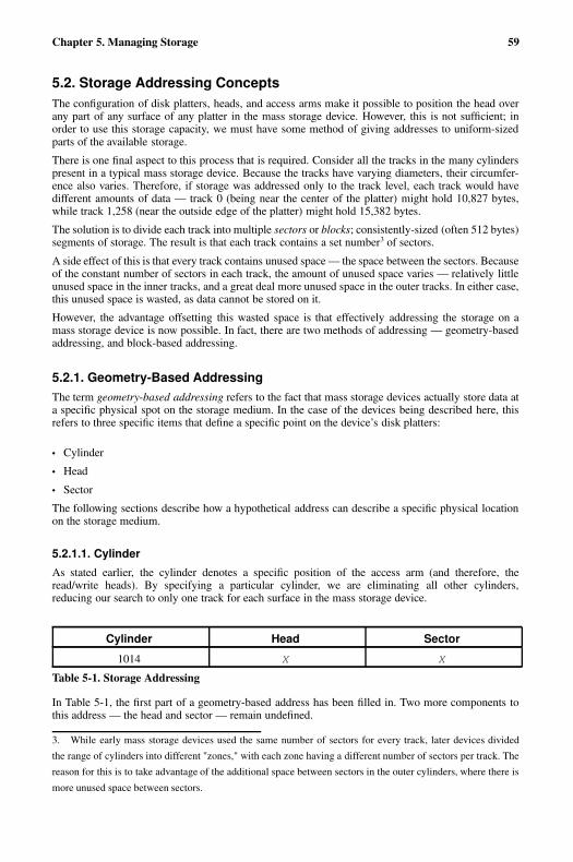
Chapter 5. Managing Storage 59
5.2. Storage Addressing ConceptsThe configuration of disk platters, heads, and access arms make it possible to position the head overany part of any surface of any platter in the mass storage device. However, this is not sufficient; inorder to use this storage capacity, we must have some method of giving addresses to uniform-sizedparts of the available storage.
There is one final aspect to this process that is required. Consider all the tracks in the many cylinderspresent in a typical mass storage device. Because the tracks have varying diameters, their circumfer-ence also varies. Therefore, if storage was addressed only to the track level, each track would havedifferent amounts of data — track 0 (being near the center of the platter) might hold 10,827 bytes,while track 1,258 (near the outside edge of the platter) might hold 15,382 bytes.
The solution is to divide each track into multiple sectors or blocks; consistently-sized (often 512 bytes)segments of storage. The result is that each track contains a set number3 of sectors.
A side effect of this is that every track contains unused space — the space between the sectors. Becauseof the constant number of sectors in each track, the amount of unused space varies — relatively littleunused space in the inner tracks, and a great deal more unused space in the outer tracks. In either case,this unused space is wasted, as data cannot be stored on it.
However, the advantage offsetting this wasted space is that effectively addressing the storage on amass storage device is now possible. In fact, there are two methods of addressing — geometry-basedaddressing, and block-based addressing.
5.2.1. Geometry-Based AddressingThe term geometry-based addressing refers to the fact that mass storage devices actually store data ata specific physical spot on the storage medium. In the case of the devices being described here, thisrefers to three specific items that define a specific point on the device’s disk platters:
• Cylinder
• Head
• Sector
The following sections describe how a hypothetical address can describe a specific physical locationon the storage medium.
5.2.1.1. Cylinder
As stated earlier, the cylinder denotes a specific position of the access arm (and therefore, theread/write heads). By specifying a particular cylinder, we are eliminating all other cylinders,reducing our search to only one track for each surface in the mass storage device.
Cylinder Head Sector
1014 X X
Table 5-1. Storage Addressing
In Table 5-1, the first part of a geometry-based address has been filled in. Two more components tothis address — the head and sector — remain undefined.
3. While early mass storage devices used the same number of sectors for every track, later devices divided
the range of cylinders into different "zones," with each zone having a different number of sectors per track. The
reason for this is to take advantage of the additional space between sectors in the outer cylinders, where there is
more unused space between sectors.

60 Chapter 5. Managing Storage
5.2.1.2. Head
Although in the strictest sense we are selecting a particular disk platter, because each surface has aread/write head dedicated to it, it is easier to think in terms of interacting with a specific head. Infact, the device’s underlying electronics actually select one head and — deselecting the rest — onlyinteract with the selected head for the duration of the I/O operation. All other tracks that make up thecurrent cylinder have now been eliminated.
Cylinder Head Sector
1014 2 X
Table 5-2. Storage Addressing
In Table 5-2, the first two parts of a geometry-based address have been filled in. One final componentto this address — the sector — remains undefined.
5.2.1.3. Sector
By specifying a particular sector, we have completed the addressing, and have uniquely identified thedesired block of data.
Cylinder Head Sector
1014 2 12
Table 5-3. Storage Addressing
In Table 5-3, the complete geometry-based address has been filled in. This address identifies thelocation of one specific block out of all the other blocks on this device.
5.2.1.4. Problems with Geometry-Based Addressing
While geometry-based addressing is straightforward, there is an area of abiguity that can cause prob-lems. The ambiguity is in numbering the cylinders, heads, and sectors.
It is true that each geometry-based address uniquely identifies one specific data block, but that onlyapplies if the numbering scheme for the cylinders, heads, and sectors is not changed. If the numberingscheme changes (such as when the hardware/software interacting with the storage device changes),then all bets are off.
Because of this potential for ambiguity, a different approach to addressing was developed. The nextsection describes it in more detail.
5.2.2. Block-Based AddressingBlock-based addressing is much more straightforward than geometry-based addressing. With block-based addressing, every data block is given a unique number. This number is passed from the computerto the mass storage device, which then internally performs the conversion to the geometry-basedaddress required by the device’s control circuitry.
Because the conversion to a geometry-based address is always done by the device itself, it will alwaysbe consistent, eliminating the problem inherent with giving the device geometry-based addressing.
Chapter 5. Managing Storage 61
5.3. Mass Storage Device InterfacesEvery device used in a computer system must have some means of attaching to that computer system.This attachment point is known as an interface. Mass storage devices are no different — they haveinterfaces too. Interfaces are important for two main reasons:
• There are many different (mostly incompatible) interfaces
• Different interfaces have different performance and price characteristics
Unfortunately, there is no single universal device interface and not even a single mass storage deviceinterface. Therefore, system administrators must be aware of the interface(s) supported by their orga-nization’s systems. Otherwise, there is a real risk of purchasing the wrong hardware when a systemupgrade is planned.
Different interfaces have different performance capabilities, making some interfaces more suitable forcertain environments than others. For example, interfaces capable of supporting high-speed devicesare more suitable for server environments, while slower interfaces would be sufficient for light desktopusage. Such differences in performance also lead to differences in price, meaning that — as always— you get what you pay for. High-performance computing does not come cheaply.
5.3.1. Historical BackgroundOver the years there have been many different interfaces created for mass storage devices. Some havefallen by the wayside, and some are still in use today. However, the following list is provided to givean idea of the scope of interface development over the past thirty years and to provide perspective onthe interfaces in use today.
FD-400
An interface originally designed for the original 8-inch floppy drives in the mid-70s. Used a44-conductor cable with an circuit board edge connector that supplied both power and data.
SA-400
Another floppy disk drive interface (this time originally developed in the late-70s for the then-new 5.25 inch floppy drive). Used a 34-conductor cable with a standard socket connector. Aslightly modified version of this interface is still used today for 5.25 inch floppy and 3.5 inchdiskette drives.
IPI
Standing for Intelligent Peripheral Interface, this interface was used on the 8 and 14-inch diskdrives used on minicomputers of the 1970s.
SMD
A successor to IPI, SMD (stands for Storage Module Device) was used on 8 and 14-inch mini-computer hard drives in the 70s and 80s.
ST506/412
A hard drive interface dating from the early 80s. Used in many personal computers of the day,this interface used two cables — one 34-conductor and one 20-conductor.
ESDI
Standing for Enhanced Small Device Interface, this interface was considered a successor toST506/412 with faster transfer rates and larger supported drive sizes. Dating from the mid-80s,ESDI used the same two-cable connection scheme of its predecessor.
62 Chapter 5. Managing Storage
There were also proprietary interfaces from the larger computer vendors of the day (IBM and DEC,primarily). The intent behind the creation of these interfaces was to attempt to protect the extremelylucrative peripherals business for their computers. However, due to their proprietary nature, the de-vices compatible with these interfaces were more expensive than equivalent non-proprietary devices.Because of this, these interfaces failed to achieve any long-term popularity.
While proprietary interfaces have largely disappeared, and the interfaces described at the start of thissection no longer have much (if any) market share, it is important to know about these no-longer-usedinterfaces, as they prove one point — nothing in the computer industry remains constant for long.Therefore, always be on the lookout for new interface technologies; one day you might find that oneof them may prove to be a better match for your needs than the more traditional offerings you currentuse.
5.3.2. Present-Day Industry-Standard InterfacesUnlike the proprietary interfaces mentioned in the previous section, some interfaces were more widelyadopted, and turned into industry standards. Two interfaces in particular have made this transition andare at the heart of today’s storage industry:
• SCSI
• IDE
5.3.2.1. IDE/ATA
IDE stands for Integrated Drive Electronics. This interface originated in the late 80s, and uses a 40-pinconnector.
Note
Actually, the proper name for this interface is the "AT Attachment" interface (or ATA), but use of theterm "IDE" (which actually refers to an ATA-compatible mass storage device) is still used to someextent. The remainder of this section uses the interface’s proper name — ATA.
ATA implements a bus topology, with each bus supporting two mass storage devices. These twodevices are known as the master and the slave. These terms are misleading, as it implies some sort ofrelationship between the devices; that is not the case. The selection of which device is the master andwhich is the slave is normally selected through the use of jumper blocks on each device.
Note
A more recent innovation is the introduction of cable select capabilities to ATA. This innovation re-quires the use of a special cable, an ATA controller, and mass storage devices that support cableselect (normally through a "cable select" jumper setting). When properly configured, cable selecteliminates the need to change jumpers when moving devices; instead, the device’s position on theATA cable denotes whether it is master or slave.
A variation of this interface illustrates the unique ways in which technologies can be mixed andalso introduces our next industry-standard interface. ATAPI is a variation of the ATA interface andstands for AT Attachment Packet Interface. Used primarily by CD-ROM drives, ATAPI adheres to the
Chapter 5. Managing Storage 63
electrical and mechanical aspects of the ATA interface but uses the communication protocol from thenext interface discussed — SCSI.
5.3.2.2. SCSI
Formally known as the Small Computer System Interface, SCSI as it is known today originated inthe early 80s and was declared a standard in 1986. Like ATA, SCSI makes use of a bus topology.However, there the similarities end.
Using a bus topology means that every device on the bus must be uniquely identified somehow. WhileATA supports only two different devices for each bus and gives each one a specific name, SCSI doesthis by assigning each device on a SCSI bus a unique numeric address or SCSI ID. Each device on aSCSI bus must be configured (usually by jumpers or switches4) to respond to its SCSI ID.
Before continuing any further in this discussion, it is important to note that the SCSI standard does notrepresent a single interface, but a family of interfaces. There are several areas in which SCSI varies:
• Bus width
• Bus speed
• Electrical characteristics
The original SCSI standard described a bus topology in which eight lines in the bus were used for datatransfer. This meant that the first SCSI devices could transfer data one byte at a time. In later years,the standard was expanded to permit implementations where sixteen lines could be used, doublingthe amount of data that devices could transfer. The original "8-bit" SCSI implementations were thenreferred to as narrow SCSI, while the newer 16-bit implementations were known as wide SCSI.
Originally, the bus speed for SCSI was set to 5MHz, permitting a 5MB/second transfer rate on theoriginal 8-bit SCSI bus. However, subsequent revisions to the standard doubled that speed to 10MHz,resulting in 10MB/second for narrow SCSI and 20MB/second for wide SCSI. As with the bus width,the changes in bus speed received new names, with the 10MHz bus speed being termed fast. Sub-sequent enhancements pushed bus speeds to ultra (20MHz), fast-40 (40MHz), and fast-805. Furtherincreases in transfer rates lead to several different versions of the ultra160 bus speed.
By combining these terms, various SCSI configurations can be concisely named. For example, "ultra-wide SCSI" refers to a 16-bit SCSI bus running at 20MHz.
The original SCSI standard used single-ended signaling; this is an electrical configuration where onlyone conductor is used to pass an electrical signal. Later implementations also permitted the use ofdifferential signaling, where two conductors are used to pass a signal. Differential SCSI (which waslater renamed to high voltage differential or HVD SCSI) had the benefit of reduced sensitivity toelectrical noise and allowed longer cable lengths, but it never became popular in the mainstreamcomputer market. A later implementation, known as low voltage differential (LVD), has finally brokenthrough to the mainstream and is a requirement for the higher bus speeds.
The width of a SCSI bus not only dictates the amount of data that can be transferred with each clockcycle, but it also determines how many devices can be connected to a bus. Regular SCSI supports 8uniquely-addressed devices, while wide SCSI supports 16. In either case, you must make sure that alldevices are set to use a unique SCSI ID. Two devices sharing a single ID will cause problems thatcould lead to data corruption.
One other thing to keep in mind is that every device on the bus uses an ID. This includes the SCSIcontroller. Quite often system administrators forget this and unwittingly set a device to use the same
4. Some storage hardware (usually those that incorporate removable drive "carriers") is designed so that the act
of plugging a module into place automatically sets the SCSI ID to an appropriate value.5. Fast-80 is not technically a change in bus speed; instead the 40MHz bus was retained, but data was clocked
at both the rising and falling of each clock pulse, effectivly doubling the throughput.

64 Chapter 5. Managing Storage
SCSI ID as the bus’s controller. This also means that, in practice, only 7 (or 15, for wide SCSI) devicesmay be present on a single bus, as each bus must reserve an ID for the controller.
Tip
Most SCSI implementations include some means of scanning the SCSI bus; this is often used toconfirm that all the devices are properly configured. If a bus scan returns the same device for everysingle SCSI ID, that device has been incorrectly set to the same SCSI ID as the SCSI controller. Toresolve the problem, reconfigure the device to use a different (and unique) SCSI ID.
Because of SCSI’s bus-oriented architecture, it is necessary to properly terminate both ends of the bus.Termination is accomplished by placing a load of the correct electrical impedance on each conductorcomprising the SCSI bus. Termination is an electrical requirement; without it, the various signalspresent on the bus would be reflected off the ends of the bus, garbling all communication.
Many (but not all) SCSI devices come with internal terminators that can be enabled or disabled usingjumpers or switches. External terminators are also available.
One last thing to keep in mind about SCSI — it is not just an interface standard for mass storagedevices. Many other devices (such as scanners, printers, and communications devices) use SCSI.Although these are much less common than SCSI mass storage devices, they do exist. However, it islikely that, with the advent of USB and IEEE-1394 (often called Firewire), these interfaces will beused more for these types of devices in the future.
Tip
The USB and IEEE-1394 interfaces are also starting to make inroads in the mass storage arena;however, no native USB or IEEE-1394 mass-storage devices currently exist. Instead, the present-day offerings are based on ATA or SCSI devices with external conversion circuitry.
No matter what interface a mass storage device uses, the inner workings of the device has a bearingon its performance. The following section explores this important subject.
5.4. Hard Drive Performance CharacteristicsHard drive performance characteristics have already been introduced in Section 4.2.4 Hard Drives;this section discusses the matter in more depth. This is important for system administrators to under-stand, because without at least basic knowledge of how hard drives operate, it is possible to unwittinglymaking changes to your system configuration that could negatively impact its performance.
The time it takes for a hard drive to respond to and complete an I/O request is dependent on twothings:
• The hard drive’s mechanical and electrical limitations
• The I/O load imposed by the system
The following sections explore these aspects of hard drive performance in more depth.
Chapter 5. Managing Storage 65
5.4.1. Mechanical/Electrical LimitationsBecause hard drives are electro-mechanical devices, they are subject to various limitations on theirspeed and performance. Every I/O request requires the various components of the drive to work to-gether to satisfy the request. Because each of these components have different performance character-istics, the overall performance of the hard drive is determined by the sum of the performance of theindividual components.
However, the electronic components are at least an order of magnitude faster than the mechanicalcomponents. Therefore, it is the mechanical components that have the greatest impact on overall harddrive performance.
Tip
The most effective way to improve hard drive performance is to reduce the drive’s mechanical activityas much as possible.
The average access time of a typical hard drive is roughly 5.6 milliseconds. The following sectionsbreak this figure down in more detail, showing how each component impacts the hard drive’s overallperformance.
5.4.1.1. Command Processing Time
All hard drives produced today have sophisticated embedded computer systems controlling their op-eration. These computer systems perform the following tasks:
• Interacting with the outside world via hard drive’s interface
• Controlling the operation of the rest of the hard drive’s components, recovering from any errorconditions that might arise
• Processing the raw data read from and written to the actual storage media
Even though the microprocessors used in hard drives are relatively powerful, the tasks assigned tothem take time to perform. On average, this time is in the range of .003 milliseconds.
5.4.1.2. Heads Reading/Writing Data
The hard drive’s read/write heads only work when the disk platters over which they "fly" are spinning.Because it is the movement of the media under the heads that allows the data to be read or written, thetime that it takes for media containing the desired sector to pass completely underneath the head is thesole determinant of the head’s contribution to total access time. This averages .00014 milliseconds fora 10,000 RPM drive with 700 sectors per track.
5.4.1.3. Rotational Latency
Because a hard drive’s disk platters are continuously spinning, when the I/O request arrives it ishighly unlikely that the platter will be at exactly the right point in its rotation necessary to access thedesired sector. Therefore, even if the rest of the drive is ready to access that sector, it is necessaryfor everything to wait while the platter rotates, bringing the desired sector into position under theread/write head.
This is the reason why higher-performance hard drives typically rotate their disk platters at higherspeeds. Today, speeds of 15,000 RPM are reserved for the highest-performing drives, while 5,400
66 Chapter 5. Managing Storage
RPM is considered adequate only for entry-level drives. This averages .05 milliseconds for a 10,000RPM drive.
5.4.1.4. Access Arm Movement
If there is one component in hard drives that can be considered its Achilles’ Heel, it is the access arm.The reason for this is that the access arm must move very quickly and accurately over relatively longdistances. In addition, the access arm movement is not continuous — it must rapidly accelerate as itapproaches the desired cylinder and then just as rapidly decelerate to avoid overshooting. Therefore,the access arm must be strong (to survive the violent forces caused by the need for quick movement)but also light (so that there is less mass to accelerate/decelerate).
Achieving these conflicting goals is difficult, a fact that is shown by how relatively much time theaccess arm movement takes when compared to the time taken by the other components. Therefore,the movement of the access arm is the primary determinant of a hard drive’s overall performance,averaging 5.5 milliseconds.
5.4.2. I/O Loads and PerformanceThe other thing that controls hard drive performance is the I/O load to which a hard drive is subjected.Some of the specific aspects of the I/O load are:
• The amount of reads versus writes
• The number of current readers/writers
• The locality of reads/writes
These are discussed in more detail in the following sections.
5.4.2.1. Reads Versus Writes
For the average hard drive using magnetic media for data storage, the number of read I/O operationsversus the number of write I/O operations is not of much concern, as reading and writing data takethe same amount of time6. However, other mass storage technologies take different amounts of timeto process reads and writes7.
The impact of this is that devices that take longer to process write I/O operations (for example) willbe able to handle fewer write I/Os than read I/Os. Looked at another way, a write I/O will consumemore of the device’s ability to process I/O requests than will a read I/O.
5.4.2.2. Multiple Readers/Writers
A hard drive that processes I/O requests from multiple sources experiences a different load than ahard drive that services I/O requests from only one source. The main reason for this is due to the factthat multiple I/O requesters have the potential to bring higher I/O loads to bear on a hard drive than asingle I/O requester.
6. Actually, this is not entirely true. All hard drives include some amount of on-board cache memory that is used
to improve read performance. However, any I/O request to read data must eventually be satisfied by physically
reading the data from the storage medium. This means that, while cache may alleviate read I/O performance
problems, it can never totally eliminate the time required to physically read the data from the storage medium.7. Some optical disk drives exhibit this behavior, due to the physical constraints of the technologies used to
implement optical data storage.
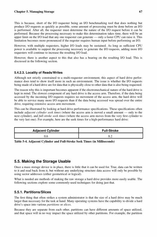
Chapter 5. Managing Storage 67
This is because, short of the I/O requester being an I/O benchmarking tool that does nothing butproduce I/O requests as quickly as possible, some amount of processing must be done before an I/Ois performed. After all, the requester must determine the nature of the I/O request before it can beperformed. Because the processing necessary to make this determination takes time, there will be anupper limit on the I/O load that any one requester can generate — only a faster CPU can raise it. Thislimitation becomes more pronounced if the reqester requires human input before performing an I/O.
However, with multiple requesters, higher I/O loads may be sustained. As long as sufficient CPUpower is available to support the processing necessary to generate the I/O requests, adding more I/Orequesters will continue to increase the resulting I/O load.
However, there is another aspect to this that also has a bearing on the resulting I/O load. This isdiscussed in the following section.
5.4.2.3. Locality of Reads/Writes
Although not strictly constrained to a multi-requester environment, this aspect of hard drive perfor-mance does tend to show itself more in such an environment. The issue is whether the I/O requestsbeing made of a hard drive are for data that is physically close to other data that is also being requested.
The reason why this is important becomes apparent if the electromechanical nature of the hard drive iskept in mind. The slowest component of any hard drive is the access arm. Therefore, if the data beingaccessed by the incoming I/O requests requires no movement of the access arm, the hard drive willbe able to service many more I/O requests than if the data being accessed was spread over the entiredrive, requiring extensive access arm movement.
This can be illustrated by looking at hard drive performance specifications. These specifications ofteninclude adjacent cylinder seek times (where the access arm is moved a small amount — only to thenext cylinder), and full-stroke seek times (where the access arm moves from the very first cylinder tothe very last one). For example, here are the seek times for a high-performance hard drive:
Adjacent Cylinder Full-Stroke
0.6 8.2
Table 5-4. Adjacent Cylinder and Full-Stroke Seek Times (in Milliseconds)
5.5. Making the Storage UsableOnce a mass storage device is in place, there is little that it can be used for. True, data can be writtento it and read back from it, but without any underlying structure data access will only be possible byusing sector addresses (either geometrical or logical).
What is needed are methods of making the raw storage a hard drive provides more easily usable. Thefollowing sections explore some commonly-used techniques for doing just that.
5.5.1. Partitions/SlicesThe first thing that often strikes a system administrator is that the size of a hard drive may be muchlarger than necessary for the task at hand. Many operating systems have the capability to divide a harddrive’s space into various partitions or slices.
Because they are separate from each other, partitions can have different amounts of space utilized,and that space will in no way impact the space utilized by other partitions. For example, the partition
68 Chapter 5. Managing Storage
holding the files comprising the operating system will not be affected even if the partition holding theusers’ files becomes full. The operating system will still have free space for its own use.
Although it is somewhat simplistic, you can think of partitions as being similar to individual diskdrives. In fact, some operating systems actually refer to partitions as "drives". However, this viewpointis not entirely accurate; therefore, it is important that we look at partitions more closely.
5.5.1.1. Partition Attributes
Partitions are defined by the following attributes:
• Partition geometry
• Partition type
• Partition type field
These attributes are explored in more detail in the following sections.
5.5.1.1.1. Geometry
A partition’s geometry refers to its physical placement on a disk drive. The geometry can be specifiedin terms of starting and ending cylinders, heads, and sectors, although most often partitions start andend on cylinder boundaries. A partition’s size is then defined as the amount of storage between thestarting and ending cylinders.
5.5.1.1.2. Partition Type
The partition type refers to the partition’s relationship with the other partitions on the disk drive. Thereare three different partition types:
• Primary partitions
• Extended partitions
• Logical partitions
The following sections describe each partition type.
5.5.1.1.2.1. Primary Partitions
Primary partitions are partitions that take up one of the four primary partition slots in the disk drive’spartition table.
5.5.1.1.2.2. Extended Partitions
Extended partitions were developed in response to the need for more than four partitions per disk drive.An extended partition can itself contain multiple partitions, greatly extending the number of partitionspossible on a single drive. The introduction of extended partitions was driven by the ever-increasingcapacities of new disk drives.

Chapter 5. Managing Storage 69
5.5.1.1.2.3. Logical Partitions
Logical partitions are those partitions contained within an extended partition; in terms of use they areno different than a non-extended primary partition.
5.5.1.1.3. Partition Type Field
Each partition has a type field that contains a code indicating the partition’s anticipated usage. Thetype field may or may not reflect the computer’s operating system. Instead, it may reflect how data isto be stored within the partition. The following section contains more information on this importantpoint.
5.5.2. File SystemsEven with the proper mass storage device, properly configured, and appropriately partitioned, wewould still be unable to store and retrieve information easily — we are missing a way of structuringand organizing that information. What we need is a file system.
The concept of a file system is so fundamental to the use of mass storage devices that the average com-puter user often does not even make the distinction between the two. However, system administratorscannot afford to ignore file systems and their impact on day-to-day work.
A file system is a method of representing data on a mass storage device. File systems usually includethe following features:
• File-based data storage
• Hierarchical directory (sometimes known as "folder") structure
• Tracking of file creation, access, and modification times
• Some level of control over the type of access allowed to a file
• Some concept of file ownership
• Accounting of space utilized
Not all file systems posses every one of these features. For example, a file system constructed for asingle-user operating system could easily use a more simplified method of access control and couldconceivably do away with support for file ownership altogether.
One point to keep in mind is that the file system used can have a large impact on the nature of yourdaily workload. By ensuring that the file system you use in your organization closely matches yourorganization’s functional requirements, you can ensure that not only is the file system up to the task,but that it is more easily and efficiently maintainable.
With this in mind, the following sections explore these features in more detail.
5.5.2.1. File-Based Storage
While file systems that use the file metaphor for data storage are so nearly universal as to be considereda given, there are still some aspects that should be considered here.
First is to be aware of any restrictions on file names. For instance, what characters are permitted in afile name? What is the maximum file name length? These questions are important, as it dictates thosefile names that can be used and those that cannot. Older operating systems with more primitive filesystems often allowed only alphanumeric characters (and uppercase at that), and only traditional 8.3file names (meaning an eight-character file name, followed by a three-character file extension).
70 Chapter 5. Managing Storage
5.5.2.2. Hierarchical Directory Structure
While the file systems used in some very old operating systems did not include the concept of direc-tories, all commonly-used file systems today include this feature. Directories are themselves usuallyimplemented as files, meaning that no special utilities are required to maintain them.
Furthermore, because directories are themselves files, and directories contain files, directories cantherefore contain other directories, making a multi-level directory hierarchy possible. This is a pow-erful concept with which all system administrators should be thoroughly familiar.
Using multi-level directory hierarchies can make file management much easer for you and for yourusers.
5.5.2.3. Tracking of File Creation, Access, Modification Times
Most file systems keep track of the time at which a file was created; some also track modificationand access times. Over and above the convenience of being able to determine when a given file wascreated, accessed, or modified, these dates are vital for the proper operation of incremental backups.
More information on how backups make use of these file system features can be found in Section 8.2Backups.
5.5.2.4. Access Control
Access control is one area where file systems differ dramatically. Some file systems have no clear-cutaccess control model, while others are much more sophisticated. In general terms, most modern dayfile systems combine two components into a cohesive access control methodology:
• User identification
• Permitted action list
User identification means that the file system (and the underlying operating system) must first becapable of uniquely identifying individual users. This makes it possible to have full accountabilitywith respect to any operations on the file system level. Another often-helpful feature is that of usergroups — creating ad-hoc collections of users. Groups are most often used by organizations whereusers may be members of one or more projects. Another feature that some file systems support is thecreation of generic identifiers that can be assigned to one or more users.
Next, the file system must be capable of maintaining lists of actions that are permitted (or not permit-ted) against each file. The most commonly-tracked actions are:
• Reading the file
• Writing the file
• Executing the file
Various file systems may extend the list to include other actions such as deleting, or even the abilityto make changes related to a file’s access control.
5.5.2.5. Accounting of Space Utilized
One constant in a system administrator’s life is that there is never enough free space, and even if thereis, it will not remain free for long. Therefore, a system administrator should at least be able to easilydetermine the level of free space available for each file system. In addition, file systems with well-defined user identification capabilities often include the capability to display the amount of space aparticular user has consumed.
Chapter 5. Managing Storage 71
This feature is vital in large multi-user environments, as it is an unfortunate fact of life that the 80/20rule often applies to disk space — 20 percent of your users will be responsible for consuming 80percent of your available disk space. By making it easy to determine which users are in that 20 percent,you will be able to more effectively manage your storage-related assets.
Taking this a step further, some file systems include the ability to set per-user limits (often known asdisk quotas) on the amount of disk space that can be consumed. The specifics vary from file system tofile system, but in general each user can be assigned a specific amount of storage that a user can use.Beyond that, various file systems differ. Some file systems permit the user to exceed their limit for onetime only, while others implement a "grace period" during which a second, higher limit is applied.
5.5.3. Directory StructureMany system administrators give little thought to how the storage they make available to users todayis actually going to be used tomorrow. However, a bit of thought spent on this matter before handingover the storage to users can save a great deal of unnecessary effort later on.
The main thing that system administrators can do is to use directories and subdirectories to structurethe storage available in an understandable way. There are several benefits to this approach:
• More easily understood
• More flexibility in the future
By enforcing some level of structure on your storage, it can be more easily understood. For example,consider a large mult-user system. Instead of placing all user directories in one large directory, itmight make sense to use subdirectories that mirror your organization’s structure. In this way, peoplethat work in accounting will have their directories under a directory named accounting, people thatwork in engineering would have their directories under engineering, and so on.
The benefits of such an approach would be that it would be easier on a day-to-day basis to keep trackof the storage needs (and usage) of each part of your organization. Obtaining a listing of the filesused by everyone in human resources is straightforward. Backing up all the files used by the legaldepartment is easy.
With the appropriate structure, flexibility is increased. To continue using the previous example, assumefor a moment that the engineering department is due to take on several large new projects. Because ofthis, many new engineers will be hired in the near future. However, there is not enough free storageavailable to support the expected additions to engineering.
However, since every person in engineering has their files stored under the Engineering directory,it would be a straightforward process to:
• Procure the additional storage necessary to support Engineering
• Back up everything under the Engineering directory
• Restore the backup onto the new storage
• Rename the Engineering directory on the original storage to something like Engineering-archive (before deleting it entirely after running smoothly with the new configuration for a month)
• Make the necessary changes so that all Engineering personnel can access their files on the newstorage
Of course, such an approach does have its shortcomings. For example, if people frequently movebetween departments, you must have a way of being informed of such transfers, and modify thedirectory structure appropriately. Otherwise, the structure will no longer reflect reality, which willmake more work — not less — for you in the long run.
72 Chapter 5. Managing Storage
5.5.4. Enabling Storage AccessOnce a mass storage device has been properly partitioned, and a file system written to it, the storageis available for general use.
For some operating systems, this is true — as soon as the operating system detects the new massstorage device, it can be formatted by the system administrator and may be accessed immediatelywith no additional effort.
Other operating systems require an additional step. This step — often referred to as mounting —directs the operating system as to how the storage may be accessed.
5.6. Advanced Storage TechnologiesAlthough everything presented in this chapter so far has dealt only with single hard drives directly-attached to a system, there are other, more advanced options that you can explore. The followingsections describe some of the more common approaches to expanding your mass storage options.
5.6.1. Network-Accessible StorageCombining network and mass storage technologies can result in a great deal more flexibility for systemadministrators. There are two benefits that are possible with this type of configuration:
• Consolidation of storage
• Simplified administration
Storage can be consolidated by deploying high-performance servers with high-speed network con-nectivity and configured with large amounts of fast storage. Given an appropriate configuration, it ispossible to provide storage access at speeds comparable to locally-attached storage. Furthermore, theshared nature of such a configuration often makes it possible to reduce costs, as the expenses associ-ated with providing centralized, shared storage can be less than providing the equivalent storage foreach and every client. In addition, free space is consolidated, instead of being spread out (and notwidely usable) across many clients.
Centralized storage servers also can make many administrative tasks easier. For instance, monitoringfree space is much easier when the storage to be monitored exists on one system. Backups can be vastlysimplified; network-aware backups are possible, but require more work to configure and maintain thanthe straightforward "single-system" backup of a storage server.
There are a number of different networked storage technologies available; choosing one can be diffi-cult. Nearly every operating system on the market today includes some means of accessing network-accessible storage, but the different technologies are in compatible with each other. What is the bestapproach to determining which technology to deploy?
The approach that usually provides the best results is to let the built-in capabilities of the client decidethe issue. There are a number of reasons for this:
• Minimal client integration issues
• Minimal work on each client system
• Low per-client cost of entry
Keep in mind that any client-related issues are multiplied by the number of clients in your organi-zation. By using the clients’ built-in capabilities, you have no additional software to install on eachclient (incurring zero additional cost in software prodcurement). And you have the best chance forgood support and integration with the client operating system.
Chapter 5. Managing Storage 73
There is a downside, however. This means that the server environment must be up to the task ofproviding good support for the network-accessible storage technologies required by the clients. Incases where the server and client operating systems are one and the same, there is normally no issue.Otherwise, it will be necessary to invest time and effort in making the server "speak" the clients’language. Often this tradeoff is more than justified.
5.6.2. RAID-Based StorageOne skill that a system administrator should cultivate is the ability to look at complex system config-urations, and observe the different shortcomings inherent in each configuration. While this might, atfirst glance, seem to be a rather depressing viewpoint to take, it can be a great way to look beyond theshiny new boxes and visualize some future Saturday night with all production down due to a failurethat could easily have been avoided with a bit of forethought.
With this in mind, let us use what we now know about disk-based storage and see if we can determinethe ways that disk drives can cause problems. First, consider an outright hardware failure:
A disk drive with four partitions on it dies completely: what happens to the data on those partitions?
It is immediately unavailable (at least until the failing unit can be replaced, and the data restored froma recent backup).
A disk drive with a single partition on it is operating at the limits of its design due to massive I/Oloads: what happens to applications that require access to the data on that partition?
The applications slow down because the disk drive cannot process reads and writes any faster.
You have a large data file that is slowly growing in size; soon it will be larger than the largest diskdrive available for your system. What happens then?
The disk drive fills up, the data file stops growing, and its associated applications stop running.
Just one of these problems could cripple a data center, yet system administrators must face these kindsof issues every day. What can be done?
Fortunately, there is one technology that can address each one of these issues. The name for thattechnology is RAID.
5.6.2.1. Basic Concepts
RAID is an acronym standing for Redundant Array of Independent Disks8. As the name implies,RAID is a way for multiple disk drives to act as if they were a single disk drive.
RAID techniques were first developed by researchers at the University of California, Berkeley in themid-1980s. At the time, there was a large gap in price between the high-performance disk drives usedon the large computer installations of the day, and the smaller, slower disk drives used by the still-young personal computer industry. RAID was viewed as a method of having several less expensivedisk drives fill in for one higher-priced unit.
More importantly, RAID arrays can be constructed in different ways, resulting in different character-istics depending on the final configuration. Let us look at the different configurations (known as RAIDlevels) in more detail.
8. When early RAID research began, the acronym stood for Redundant Array of Inexpensive Disks, but over
time the "standalone" disks that RAID was intended to supplant became cheaper and cheaper, rendering the price
comparison meaningless.
74 Chapter 5. Managing Storage
5.6.2.1.1. RAID Levels
The Berkeley researchers originally defined five different RAID levels and numbered them "1"through "5." In time, additional RAID levels were defined by other researchers and members of thestorage industry. Not all RAID levels were equally useful; some were of interest only for researchpurposes, and others could not be economically implemented.
In the end, there were three RAID levels that ended up seeing widespread usage:
• Level 0
• Level 1
• Level 5
The following sections discuss each of these levels in more detail.
5.6.2.1.1.1. RAID 0
The disk configuration known as RAID level 0 is a bit misleading, as this is the only RAID levelthat employs absolutely no redundancy. However, even though RAID 0 has no advantages from areliability standpoint, it does have other benefits.
A RAID 0 array consists of two or more disk drives. The available storage capacity on each drive isdivided into chunks, which represents some multiple of the drives’ native block size. Data written tothe array will be written, chunk by chunk, to each drive in the array. The chunks can be thought of asforming stripes across each drive in the array; hence the other term for RAID 0: striping.
For example, with a two-drive array and a 4KB chunk size, writing 12KB of data to the array wouldresult in the data being written in three 4KB chunks to the following drives:
• The first 4KB would be written to the first drive, into the first chunk
• The second 4KB would be written to the second drive, into the first chunk
• The last 4KB would be written to the first drive, into the second chunk
Compared to a single disk drive, the advantages to RAID 0 are:
• Larger total size — RAID 0 arrays can be constructed that are larger than a single disk drive, makingit easier to store larger data files
• Better read/write performance — The I/O load on a RAID 0 array will be spread evenly among allthe drives in the array (Assuming all the I/O is not concentrated on a single chunk)
• No wasted space — All available storage on all drives in the array are available for data storage
Compared to a single disk drive, RAID 0 has the following disadvantage:
• Less reliability — Every drive in a RAID 0 array must be operative in order for the array to beavailable; a single drive failure in an N -drive RAID 0 array will remove 1/N th of all the data,rendering the array useless
Tip
If you have trouble keeping the different RAID levels straight, just remember that RAID 0 has zeropercent redundancy.
Chapter 5. Managing Storage 75
5.6.2.1.1.2. RAID 1
RAID 1 uses two (although some implementations support more) identical disk drives. All data iswritten to both drives, making them mirror images of each other. That is why RAID 1 is often knownas mirroring.
Whenever data is written to a RAID 1 array, two physical writes must take place: one to the first drive,and one to the second drive. Reading data, on the other hand, only needs to take place once and eitherdrive in the array can be used.
Compared to a single disk drive, a RAID 1 array has the following advantages:
• Improved redundancy — Even if one drive in the array were to fail, the data would still be accessible
• Improved read performance — With both drives operational, reads can be evenly split betweenthem, reducing per-drive I/O loads
When compared to a single disk drive, a RAID 1 array has some disadvantages:
• Maximum array size is limited to the largest single drive available.
• Reduced write performance — Because both drives must be kept up-to-date, all write I/Os must beperformed by both drives, slowing the overall process of writing data to the array
• Reduced cost efficiency — With one entire drive dedicated to redundancy, the cost of a RAID 1array is at least double that of a single drive
Tip
If you have trouble keeping the different RAID levels straight, just remember that RAID 1 has onehundred percent redundancy.
5.6.2.1.1.3. RAID 5
RAID 5 attempts to combine the benefits of RAID 0 and RAID 1, while minimizing their respectivedisadvantages.
Like RAID 0, a RAID 5 array consists of multiple disk drives, each divided into chunks. This allowsa RAID 5 array to be larger than any single drive. Like a RAID 1 array, a RAID 5 array uses somedisk space in a redundant fashion, improving reliability.
However, the way RAID 5 works is unlike either RAID 0 or 1.
A RAID 5 array must consist of at least three identically-sized disk drives (although more drives maybe used). Each drive is divided into chunks and data is written to the chunks in order. However, notevery chunk is dedicated to data storage as it is in RAID 0. Instead, in an array with n disk drives init, every nth chunk is dedicated to parity.
Chunks containing parity make it possible to recover data should one of the drives in the array fail.The parity in chunk x is calculated by mathematically combining the data from each chunk x storedon all the other drives in the array. If the data in a chunk is updated, the corresponding parity chunkmust be recalculated and updated as well.
This also means that every time data is written to the array, at least two drives are written to: the driveholding the data, and the drive containing the parity chunk.
One key point to keep in mind is that the parity chunks are not concentrated on any one drive in thearray. Instead, they are spread evenly across all the drives. Even though dedicating a specific driveto contain nothing but parity is possible (and, in fact, this configuration is known as RAID level 4),
76 Chapter 5. Managing Storage
the constant updating of parity as data is written to the array would mean that the parity drive couldbecome a performance bottleneck. By spreading the parity information evenly throughout the array,this impact is reduced.
However, it is important to keep in mind the impact of parity on the overall storage capacity of thearray. Even though the parity information is spread evenly across all the drives in the array, the amountof available storage is reduced by the size of one drive.
Compared to a single drive, a RAID 5 array has the following advantages:
• Improved redundancy — If one drive in the array fails, the parity information can be used to recon-struct the missing data chunks, all while keeping the array available for use9
• Improved read performance — Due to the RAID 0-like way data is divided between drives in thearray, read I/O activity is spread evenly between all the drives
• Reasonably good cost efficiency — For a RAID 5 array of n drives, only 1/nth of the total availablestorage is dedicated to redundancy
Compared to a single drive, a RAID 5 array has the following disadvantage:
• Reduced write performance — Because each write to the array results in at least two writes to thephysical drives (one write for the data and one for the parity), write performance is worse than asingle drive10
5.6.2.1.1.4. Nested RAID Levels
As should be obvious from the discussion of the various RAID levels, each level has specific strengthsand weaknesses. It was not long after RAID-based storage began to be deployed that people began towonder whether different RAID levels could somehow be combined, producing arrays with all of thestrengths and none of the weaknesses of the original levels.
For example, what if the disk drives in a RAID 0 array were themselves actually RAID 1 arrays? Thiswould give the advantages of RAID 0’s speed, with the reliability of RAID 1.
This is just the kind of thing that can be done. Here are the most commonly-nested RAID levels:
• RAID 1+0
• RAID 5+0
• RAID 5+1
Because nested RAID is used in more specialized environments, we will not go into greater detailhere. However, there are two points to keep in mind when thinking about nested RAID:
• Order matters — The order in which RAID levels are nested can have a large impact on reliability.In other words, RAID 1+0 and RAID 0+1 are not the same.
• Costs can be high — If there is any disadvantage common to all nested RAID implementations, itis one of cost; for example, the smallest possible RAID 5+1 array consists of six disk drives (andeven more drives will be required for larger arrays).
Now that we have explored the concepts behind RAID, let us see how RAID can be implemented.
9. I/O performance will be reduced while operating with one drive unavailable, due to the overhead involved in
reconstructing the missing data.10. There is also an impact from the parity calculations required for each write. However, depending on the
specific RAID 5 implementation (specifically, where in the system the parity calculations are performed), this
impact can range from sizable to nearly nonexistent.
Chapter 5. Managing Storage 77
5.6.2.1.2. RAID Implementations
It is obvious from the previous sections that RAID requires additional "intelligence" over and abovethe usual disk I/O processing for individual drives. At the very least, the following tasks must beperformed:
• Dividing incoming I/O requests to the individual disks in the array
• For RAID 5, calculating parity and writing it to the appropriate drive in the array
• Monitoring the individual disks in the array and taking the appropriate action should one fail
• Controlling the rebuilding of an individual disk in the array, when that disk has been replaced orrepaired
• Providing a means to allow administrators to maintain the array (removing and adding drives, initi-ating and halting rebuilds, etc.)
There are two major methods that may be used to accomplish these tasks. The next two sections willdescribe them.
5.6.2.1.2.1. Hardware RAID
A hardware RAID implementation usually takes the form of a specialized disk controller card. Thecard performs all RAID-related functions and directly controls the individual drives in the arraysattached to it. With the proper driver, the arrays managed by a hardware RAID card appear to the hostoperating system just as if they were regular disk drives.
Most RAID controller cards work with SCSI drives, although there are some ATA-based RAID con-trollers as well. In any case, the administrative interface is usually implemented in one of three ways:
• Specialized utility programs that run as applications under the host operating system, presenting asoftware interface to the controller card
• An on-board interface using a serial port that is accessed using a terminal emulator
• A BIOS-like interface that is only accessible during the system’s power-up testing
Some RAID controllers have more than one type of administrative interface available. For obviousreasons, a software interface provides the most flexibility, as it allows administrative functions whilethe operating system is running. However, if you are booting an operating system from a RAID con-troller, an interface that does not require a running operating system is a requirement.
Because there are so many different RAID controller cards on the market, it is impossible to go intofurther detail here. The best course of action is to read the manufacturer’s documentation for moreinformation.
5.6.2.1.2.2. Software RAID
Software RAID is RAID implemented as kernel- or driver-level software for a particular operatingsystem. As such, it provides more flexibility in terms of hardware support — as long as the hardwareis supported by the operating system, RAID arrays can be configured and deployed. This can dramat-ically reduce the cost of deploying RAID by eliminating the need for expensive, specialized RAIDhardware.
Often the excess CPU power available for software RAID parity calculations can greatly exceed theprocessing power present on a RAID controller card. Therefore, some software RAID implementa-tions can actually have the capability for higher performance than hardware RAID implementations.
However, software RAID does have limitations not present in hardware RAID. The most importantone to consider is support for booting from a software RAID array. In most cases, only RAID 1 arrayscan be used for booting, as the computer’s BIOS is not RAID-aware. Since a single drive from a RAID
78 Chapter 5. Managing Storage
1 array is indistinguishable from a non-RAID boot device, the BIOS can successfully start the bootprocess; the operating system can then change over to software RAID operation once it has gainedcontrol of the system.
5.7. Storage Management Day-to-DaySystem administrators must pay attention to storage in the course of their day-to-day routine. Thereare various issues that should be kept in mind:
• Monitoring free space
• Disk quota issues
• File-related issues
• Directory-related issues
• Backup-related issues
• Performance-related issues
• Adding/removing storage
The following sections discuss each of these issues in more detail.
5.7.1. Monitoring Free SpaceMaking sure there is sufficient free space available should be at the top of every system administrator’sdaily task list. The reason why regular, frequent free space checking is so important is because freespace is so dynamic; there can be more than enough space one moment, and almost none the next.
In general, there are three reasons for insufficient free space:
• Excessive usage by a user
• Excessive usage by an application
• Normal growth in usage
These reasons are explored in more detail in the following sections.
5.7.1.1. Excessive Usage by a User
Different people have different levels of neatness. Some people would be horrified to see a speck ofdust on a table, while others would not think twice about having a collection of last year’s pizza boxesstacked by the sofa. It is the same with storage:
• Some people are very frugal in their storage usage and never leave any unneeded files hangingaround.
• Some people never seem to find the time to get rid of files that are no longer needed.
Many times where a user is responsible for using large amounts of storage, it is the second type ofperson that is found to be responsible.
Chapter 5. Managing Storage 79
5.7.1.1.1. Handling a User’s Excessive Usage
This is one area in which a system administrator needs to summon all the diplomacy and socialskills they can muster. Quite often discussions over disk space become emotional, as people viewenforcement of disk usage restrictions as making their job more difficult (or impossible), that therestrictions are unreasonably small, or that they just do not have the time to clean up their files.
The best system administrators take many factors into account in such a situation. Are the restrictionsequitable and reasonable for the type of work being done by this person? Does the person seem to beusing their disk space appropriately? Can you help the person reduce their disk usage in some way(by creating a backup CD-ROM of all emails over one year old, for example)? Your job during theconversation is to attempt to discover if this is, in fact, the case while making sure that someone thathas no real need for that much storage cleans up their act.
In any case, the thing to do is to keep the conversation on a professional, factual level. Try to addressthe user’s issues in a polite manner ("I understand you are very busy, but everyone else in your depart-ment has the same responsibility to not waste storage, and their average utilization is less than half ofyours.") while moving the conversation toward the matter at hand. Be sure to offer assistance if a lackof knowledge/experience seems to be the problem.
Approaching the situation in a sensitive but firm manner is often better than using your authorityas system administrator to force a certain outcome. You might find that sometimes a compromisebetween you and the user is necessary. This compromise can take one of three forms:
• Provide temporary space
• Make archival backups
• Give up
You might find that the user can reduce their usage if they have some amount of temporary space thatthey can use without restriction. People that often take advantage of this situation find that it allowsthem to work without worrying about space until they get to a logical stopping point, at which timethey can perform some housekeeping, and determine what files in temporary storage are really neededor not.
Warning
If you offer this situation to a user, do not fall into the trap of allowing this temporary space to be-come permanent space. Make it very clear that the space being offered is temporary, and that noguarantees can be made as to data retention; no backups of any data in temporary space are evermade.
In fact, administrators often underscore this fact by automatically deleting any files in temporarystorage that are older than a certain age (a week, for example).
Other times, the user may have many files that are so obviously old that it is unlikely continuousaccess to them is needed. Make sure you determine that this is, in fact, the case. Sometimes individualusers are responsible for maintaining an archive of old data; in these instances, you should make apoint of assisting them in that task by providing multiple backups that are treated no differently fromyour data center’s archival backups.
However, there are times when the data is of dubious value. In these instances you might find it best tooffer to make a special backup for them. You then back up the old data, and give the user the backupmedia, explaining that they are responsible for its safekeeping, and if they ever need access to anyof the data, to ask you (or your organization’s operations staff — whatever is appropriate for yourorganization) to restore it.
There are a few things to keep in mind so that this does not backfire on you. First and foremost is to notinclude files that are likely to need restoring; do not select files that are too new. Next, make sure that
80 Chapter 5. Managing Storage
you will be able to perform a restoration if one ever is requested. This means that the backup mediashould be of a type that you are reasonably sure will be used in your data center for the foreseeablefuture.
Tip
Your choice of backup media should also take into consideration those technologies that can enablethe user to handle data restoration themselves. For example, even though backing up several giga-bytes onto CD-R media is more work than issuing a single command and spinning it off to a 20GBtape cartridge, consider that the user will be able to access the data on CD-R whenever they want —without ever involving you.
5.7.1.2. Excessive Usage by an Application
Sometimes an application is responsible for excessive usage. The reasons for this can vary, but caninclude:
• Enhancements in the application’s functionality require more storage
• An increase in users using the application
• The application fails to clean up after itself, leaving no-longer-needed temporary files on disk
• The application is broken, and the bug is causing it to use more storage than it should
Your task is to determine which of the reasons from this list apply to your situation. Being aware of thestatus of the applications used in your data center should help you eliminate several of these reasons,as should your awareness of your user’s processing habits. What remains to be done is often a bit ofdetective work into where the storage has gone. This should narrow down the field substantially.
At this point you must then take the appropriate steps, be it the addition of storage to support anincreasingly-popular application, contacting the application’s developers to discuss its file handlingcharacteristics, or writing scripts to clean up after the application.
5.7.1.3. Normal Growth in Usage
Most organizations experience some level of growth over the long term. Because of this, it is normal toexpect storage utilization to increase at a similar pace. In nearly all circumstances, ongoing monitoringwill reveal the average rate of storage utilization at your organization; this rate can then be used todetermine the time at which additional storage should be procured before your free space actuallyruns out.
If you are in the position of unexpectedly running out of free space due to normal growth, you havenot been doing your job.
However, sometimes large additional demands on your systems’ storage can come up unexpectedly.Your organization may have merged with another, necessitating rapid changes in the IT infrastructure(and therefore, storage). A new high-priority project may have literally sprung up overnight. Changesto an existing application may have resulted in greatly increased storage needs.
No matter what the reason, there are times when you will be taken by surprise. To plan for theseinstances, try to configure your storage architecture for maximum flexibility. Keeping spare storageon-hand (if possible) can alleviate the impact of such unplanned events.
Chapter 5. Managing Storage 81
5.7.2. Disk Quota IssuesMany times the first thing most people think of when they think about disk quotas is using it to forceusers to keep their directories clean. While there are sites where this may be the case, it also helps tolook at the problem of disk space usage from another perspective. What about applications that, forone reason or another, consume too much disk space? It is not unheard of for applications to fail inways that cause them to consume all available disk space. In these cases, disk quotas can help limitthe damage caused by such errant applications, forcing it to stop before no free space is left on thedisk.
The hardest part of implementing and managing disk quotas revolves around the limits themselves.What should they be?
A simplistic approach would be to divide the disk space by the number of users and/or groups usingit, and use the resulting number as the per-user quota. For example, if the system has a 100GB diskdrive and 20 users, each user should be given a disk quota of no more than 5GB. That way, each userwould be guaranteed 5GB (although the disk would be 100% full at that point).
For those operating systems that support it, temporary quotas could be set somewhat higher — say7.5GB, with a permanent quota remaining at 5GB. This would have the benefit of allowing users topermanently consume no more than their percentage of the disk, but still permitting some flexibilitywhen a user reaches (and exceeds) their limit.
When using disk quotas in this manner, you are actually over-committing the available disk space.The temporary quota is 7.5GB. If all 20 users exceeded their permanent quota at the same time andattempted to approach their temporary quota, that 100GB disk would actually have to be 150GB inorder to allow everyone to reach their temporary quota at the same time.
However, in practice not everyone will exceed their permanent quota at the same time, making someamount of overcommitment a reasonable approach. Of course, the selection of permanent and tempo-rary quotas is up to the system administrator, as each site and user community is different.
5.7.3. File-Related IssuesSystem administrators often have to deal with file-related issues. The issues include:
• File Access
• File Sharing
The following sections explore these issues in more depth.
5.7.3.1. File Access
Issues relating to file access typically revolve around one scenario — a user is not able to access a filethat feel they should be able to access.
Often this is a case of user #1 wanting to give a copy of a file to user #2. In most organizations, theability for one user to access another user’s files is strictly curtailed, leading to this problem.
There are three approaches that could conceivably be taken:
• User #1 makes the necessary changes to allow user #2 to access the file wherever it currently exists.
• A file exchange area is created for such purposes; user #1 places a copy of the file there, which canthen be copied by user #2.
• User #1 uses email to give user #2 a copy of the file.
There is a problem with the first approach — depending on how access is granted, user #2 may havefull access to all of user #1’s files. Worse, it might have been done in such a way as to permit all users
82 Chapter 5. Managing Storage
in your organization access to user #1’s files. Still worse, this change may not be reversed after user#2 no longer requires access, leaving user #1’s files permanently accessible by others. Unfortunately,when users are in charge of this type of situation, security is rarely their highest priority.
The second approach eliminates the problem of making all of user #1’s files accessible to others. How-ever, once the file is in the file exchange area the file is readable (and depending on the permissions,even writable) by all other users. This approach also raises the possibility of the file exchange areabecoming filled with files, as users often forget to clean up after themselves.
The third approach, while seemingly an awkward solution, may actually be the preferable one in mostcases. With the advent of industry-standard email attachment protocols and more intelligent emailprograms, sending all kinds of files via email is a mostly foolproof operation, requiring no systemadministrator involvement. Of course, there is the chance that a user will attempt to email a 1GBdatabase file to all 150 people in Finance, so some amount of user education (and possibly limitationson email attachement size) would be prudent. Still, none of these approaches deal with the situation oftwo or more users needing ongoing access to a single file. In these cases, other methods are required.
5.7.3.2. File Sharing
When multiple users need to share a single copy of a file, allowing access by making changes to filepermissions is not the best approach. It is far preferable to formalize the file’s shared status. There areseveral reasons for this:
• Files shared out of a user’s directory are vulnerable to disappearing unexpectedly when the usereither leaves the organization or does nothing more unusual than rearranging their files.
• Maintaining shared access for more than one or two additional users becomes difficult, leading tothe longer-term problem of unnecessary work required whenever the sharing users change respon-sibilities.
Therefore, the preferred approach is to:
• Have the original user relinquish direct ownership of the file
• Create a group that will own the file
• Place the file in a shared directory that is owned by the group
• Make all users needing access to the file part of the group
Of course, this approach would work equally well with multiple files as it would with single files, andcan be used to implement shared storage for large, complex projects.
5.7.4. Adding/Removing StorageBecause the need for additional disk space is never-ending, a system administrator often will needto add disk space, while sometimes also removing older, smaller drives. This section provides anoverview of the basic process of adding and removing storage.
5.7.4.1. Adding Storage
The process of adding storage to a computer system is relatively straightforward. Here are the basicsteps:
1. Installing the hardware
2. Partitioning
Chapter 5. Managing Storage 83
3. Formatting the partition(s)
4. Updating system configuration
5. Modifying backup schedule
Let us look at each step in more detail.
5.7.4.1.1. Installing the Hardware
Before anything else can be done, the new disk drive has to be in place and accessible. While thereare many different hardware configurations possible, the following sections go through the two mostcommon situations — adding an ATA or SCSI disk drive. Even with other configurations, the basicsteps outlined here still apply.
Tip
No matter what storage hardware you use, you should always consider the load a new disk drive willadd to your computer’s I/O subsystem. In general, you should try to spread the disk I/O load over allavailable channels/buses. From a performance standpoint, this is far better than putting all disk driveson one channel and leaving another one empty and idle.
5.7.4.1.1.1. Adding ATA Disk Drives
ATA disk drives are mostly used in desktop and lower-end server systems. Nearly all systems in theseclasses have built-in ATA controllers with multiple ATA channels — normally two or four.
Each channel can support two devices — one master, and one slave. The two devices are connected tothe channel with a single cable. Therefore, the first step is to see which channels have available spacefor an additional disk drive. You will find one of three situations:
• There is a channel with only one disk drive connected to it
• There is a channel with no disk drive connected to it
• There is no space available
The first situation is usually the easiest, as it is very likely that the cable already in place has an unusedconnector into which the new disk drive can be plugged. However, if the cable in place only has twoconnectors (one for the channel and one for the already-installed disk drive), then it will be necessaryto replace the existing cable with a three-connector model.
Before installing the new disk drive, make sure that the two disk drives sharing the channel are appro-priately configured (one as master and one as slave).
The second situation is a bit more difficult, if only for the reason that a cable must be procured inorder to connect a disk drive to the channel. The new disk drive may be configured as master or slave(although traditionally the first disk drive on a channel is normally configured as master).
In the third situation, there is no space left for an additional disk drive. You must then make a decision.Do you:
• Acquire an ATA controller card, and install it
• Replace one of the installed disk drives with the newer, larger one
Adding a controller card entails checking hardware compatibility, physical capacity, and softwarecompatibility. Basically, the card must be compatible with your computer’s bus slots, there must bean open slot for it, and it must be supported by your operating system.

84 Chapter 5. Managing Storage
Replacing an installed disk drive presents a unique problem: what to do with the data on the disk?There are a few possible approaches:
• Write the data to a backup device and restore it after installing the new disk drive
• Use your network to copy the data to another system with sufficient free space, restoring the dataafter installing the new disk drive
• Use the space physically occupied by a third disk drive by:
1. Temporarily removing the third disk drive
2. Temporarily installing the new disk drive in its place
3. Copying the data to the new disk drive
4. Removing the old disk drive
5. Replacing it with the new disk drive
6. Reinstalling the temporarily-removed third disk drive
• Temporarily install the original disk drive and the new disk drive in another computer, copy the datato the new disk drive, and then install the new disk drive in the original computer
As you can see, sometimes a fair bit of effort must be expended to get the data (and the new hardware)where it needs to go. The next section explores the addition of a SCSI disk drive.
5.7.4.1.1.2. Adding SCSI Disk Drives
SCSI disk drives normally are used in higher-end workstations and server systems. Unlike ATA-basedsystems, SCSI systems may or may not have built-in SCSI controllers; some do, while others use aseparate SCSI controller card.
The capabilities of SCSI controllers (whether built-in or not) also vary widely. It may supply a narrowor wide SCSI bus. The bus speed may be normal, fast, ultra, utra2, or ultra160.
If these terms are unfamiliar to you (they were discussed briefly in Section 5.3.2.2 SCSI), you mustdetermine the capabilities of your hardware configuration and select an appropriate new disk drive.The best resource for this information would be the documentation for your system and/or SCSIadapter.
You must then determine how many SCSI buses are available on your system, and which ones haveavailable space for a new disk drive. The number of devices supported by a SCSI bus will vary ac-cording to the bus width:
• Narrow (8-bit) SCSI bus — 7 devices (plus controller)
• Wide (16-bit) SCSI bus — 15 devices (plus controller)
The first step is to see which buses have available space for an additional disk drive. You will find oneof three situations:
• There is a bus with less than the maximum number of disk drives connected to it
• There is a bus with no disk drives connected to it
• There is no space available on any bus
The first situation is usually the easiest, as it is likely that the cable in place has an unused connectorinto which the new disk drive can be plugged. However, if the cable in place does not have an un-used connector, it will be necessary to replace the existing cable with one that has at least one moreconnector.
Chapter 5. Managing Storage 85
The second situation is a bit more difficult, if only for the reason that a cable must be procured inorder to connect a disk drive to the bus.
If there is no space left for an additional disk drive, you must make a decision. Do you:
• Acquire and install a SCSI controller card
• Replace one of the installed disk drives with the new, larger one
Adding a controller card entails checking hardware compatibility, physical capacity, and softwarecompatibility. Basically, the card must be compatible with your computer’s bus slots, there must bean open slot for it, and it must be supported by your operating system.
Replacing an installed disk drive presents a unique problem: what to do with the data on the disk?There are a few possible approaches:
• Write the data to a backup device, and restore it after installing the new disk drive
• Use your network to copy the data to another system with sufficient free space, and restore afterinstalling the new disk drive
• Use the space physically occupied by a third disk drive by:
1. Temporarily removing the third disk drive
2. Temporarily installing the new disk drive in its place
3. Copying the data to the new disk drive
4. Removing the old disk drive
5. Replacing it with the new disk drive
6. Reinstalling the temporarily-removed third disk drive
• Temporarily install the original disk drive and the new disk drive in another computer, copy the datato the new disk drive, and then install the new disk drive in the original computer
Once you have an available connector in which to plug the new disk drive, you must make sure thatthe drive’s SCSI ID is set appropriately. To do this, you must know what all of the other devices onthe bus (including the controller) are using for their SCSI IDs. The easiest way to do this is to accessthe SCSI controller’s BIOS. This is normally done by pressing a specific key sequence during thesystem’s power-up sequence. You can then view the SCSI controller’s configuration, along with thedevices attached to all of its buses.
Next, you must consider proper bus termination. When adding a new disk drive, the rule is actuallyquite straightforward — if the new disk drive is the last (or only) device on the bus, it must havetermination enabled. Otherwise, termination must be disabled.
At this point, you can move on to the next step in the process — partitioning your new disk drive.
5.7.4.1.2. Partitioning
Once the disk drive has been installed, it is time to create one or more partitions to make the spaceavailable to your operating system. Although the tools will vary depending on the operating system,the basic steps are the same:
1. Select the new disk drive
2. View the disk drive’s current partition table, to ensure that the disk drive to be partitioned is, infact, the correct one
86 Chapter 5. Managing Storage
3. Delete any unwanted partitions that may already be present on the new disk drive
4. Create the new partition(s), being sure to specify the desired size and partition type
5. Save your changes and exit the partitioning program
Warning
When partitioning a new disk drive, it is vital that you are sure the disk drive you are about to partitionis the correct one. Otherwise, you may inadvertently partition a disk drive that is already in use, whichwill result in lost data.
Also make sure you have decided on the best partition size. Always give this matter serious thought,because changing it later will be much more difficult than taking a bit of time now to think thingsthrough.
5.7.4.1.3. Formatting the Partition(s)
At this point, the new disk drive has one or more partitions that have been created. However, beforethe space contained within those partitions can be used, the partitions must first be formatted. Byformatting, you are selecting a specific file system that will be used within each partition. As such,this is a pivotal time in the life of this disk drive; the choices you make here cannot be changed laterwithout going through a great deal of work.
The actual process of formatting is done by running a utiliy program; the steps involved in this varyaccording to the operating system. Once formatting is complete, the disk drive is now properly con-figured for use.
Before continuing, it is always best to double-check your work by acessing the partition(s) and makingsure everything is in order.
5.7.4.1.4. Updating System Configuration
If your operating system requires any configuration changes in order to use the new storage you haveadded, now is the time to make the necessary changes.
At this point you can be relatively confident that the new storage will be there the next time the systemboots (although if you can afford a quick reboot, it would not hurt to do so — just to be sure).
The next section explores one of the most commonly-forgotten steps in the process of adding newstorage.
5.7.4.1.5. Modifying the Backup Schedule
Assuming that the new storage is more than temporary, and requires no backups, this is the time tomake the necessary changes to your backup procedures, ensuring that the new storage will be backedup. The exact nature of what you will need to do to make this happen depends on the way thatbackups are performed on your system. However, here are some points to keep in mind while makingthe necessary changes:
• Consider what the optimal backup frequency should be
• Determine what backup style would be most appropriate (full backups only, full with incrementals,full with differentials, etc.)
Chapter 5. Managing Storage 87
• Consider the impact of the additional storage on your backup media usage, particularly as it startsto fill up
• Judge whether the additional backup will cause the backups to take too long and start using timeoutside of your alloted backup window
• Make sure that these changes are communicated to the people that need to know (other systemadministrators, operations personnel, etc.)
Once all this is done, your new storage is ready for use.
5.7.4.2. Removing Storage
Removing disk space from a system is straightforward, with most of the steps being similar to theinstallation sequence (except, of course, in reverse):
1. Move any data to be saved off the disk drive
2. Modify the backup schedule so that the disk drive will no longer be backed up
3. Update the system configuration
4. Erase the contents of the disk drive
5. Remove the disk drive
As you can see, compared to the installation process, there are a few extra steps to take. These stepsare discussed in the following sections.
5.7.4.2.1. Moving Data Off the Disk Drive
Should there be any data on the disk drive that must be saved, the first thing to do is to determinewhere the data should go. The decision depends mainly on what is going to be done with the data. Forexample, if the data is no longer going to be actively used, it should be archived, probably in the samemanner as your system backups. This means that now is the time to consider appropriate retentionperiods for this final backup.
Tip
Keep in mind that, in addition to any data retention guidelines your organization may have, there mayalso be legal requirements for retaining data for a certain length of time. Therefore, make sure youconsult with the department that had been responsible for the data while it was still in use; they willlikely know the appropriate retention period.
On the other hand, if the data will still be used, then the data should reside on the system mostappropriate for that usage. Of course, if this is the case, perhaps it would be easiest to move the databy reinstalling the disk drive on the new system. If you do this, you should make a full backup ofthe data before doing so — people have dropped disk drives full of valuable data (losing everything)while doing nothing more hazardous than walking across a data center.
5.7.4.2.2. Erase the Contents of the Disk Drive
No matter whether the disk drive has valuable data or not, it is a good idea to always erase a diskdrive’s contents prior to reassigning or relinquishing control of it. While the obvious reason is tomake sure that no sensitive information remains on the disk drive, it is also a good time to check thedisk drive’s health by performing a read-write test for bad blocks over the entire drive.
88 Chapter 5. Managing Storage
Important
Many companies (and government agencies) have specific methods of erasing data from disk drivesand other data storage media. You should always be sure you understand and abide by these require-ments; in many cases there are legal ramifications if you fail to do so. The example above should inno way be considered the ultimate method of wiping a disk drive.
In addition, organizations that work with classified data may find that the final disposition of the diskdrive may be subject to certain legally-mandated procedures (such as physical destruction of thedrive). In these instances your organization’s security department should be able to offer guidance inthis matter.
5.8. A Word About Backups. . .One of the most important factors when considering disk storage is that of backups. We have notcovered this subject here, because an in-depth section (Section 8.2 Backups) has been dedicated tobackups.
5.9. Red Hat Linux-Specific InformationDepending on your past system administration experience, managing storage under Red Hat Linuxwill either be mostly familiar or completely foreign. This section discusses aspects of storage admin-istration specific to Red Hat Linux.
5.9.1. Device Naming ConventionsAs with all Linux-like operating systems, Red Hat Linux uses device files to access all hardware (in-cluding disk drives). However, the naming conventions for attached storage devices varies somewhatbetween various Linux and Linux-like implementations. Here is how these device files are namedunder Red Hat Linux.
5.9.1.1. Device Files
Under Red Hat Linux, the device files for disk drives appear in the /dev/ directory. The format foreach file name depends on several aspects of the actual hardware and how it has been configured. Theimportant points are as follows:
• Device type
• Unit
• Partition
5.9.1.1.1. Device Type
The first two letters of the device file name refer to the specific type of device. For disk drives, thereare two device types that are most common:
• sd — The device is SCSI-based
• hd — The device is ATA-based
Chapter 5. Managing Storage 89
More information about ATA and SCSI can be found in Section 5.3.2 Present-Day Industry-StandardInterfaces.
5.9.1.1.2. Unit
Following the two-letter device type are one or two letters denoting the specific unit. The unit desig-nator starts with "a" for the first unit, "b" for the second, and so on. Therefore, the first hard drive onyour system may appear as hda or sda.
Tip
SCSI’s ability to address large numbers of devices necessitated the addition of a second unit charac-ter to support systems with more than 26 SCSI devices attached. Therefore, the first 26 SCSI harddrives on a system would be named sda through sdz, with the 27th named sdaa, the 28th namedsdab, and so on through to sddx.
5.9.1.1.3. Partition
The final part of the device file name is a number representing a specific partition on the device, start-ing with "1." The number may be one or two digits in length, depending on the number of partitionswritten to the specific device. Once the format for device file names is known, it is easy to understandwhat each refers to. Here are some examples:
• /dev/hda1 — The first partition on the first ATA drive
• /dev/sdb12 — The twelfth partition on the second SCSI drive
• /dev/sdad4 — The fourth partition on the thirtieth SCSI drive
5.9.1.1.4. Whole-Device Access
There are instances where it is necessary to access the entire device and not a specific partition. Thisis normally done when the device is not partitioned or does not support standard partitions (such as aCD-ROM drive). In these cases, the partition number is omitted:
• /dev/hdc — The entire third ATA device
• /dev/sdb — The entire second SCSI device
However, most disk drives use partitions (more information on partitioning under Red Hat Linux canbe found in Section 5.9.7.1 Adding Storage).
5.9.2. File System BasicsRed Hat Linux includes support for many popular file systems, making it possible to easily access thefile systems of other operating systems.
This is particularly useful in dual-boot scenarios and when migrating files from one operating systemto another.
The supported file systems include (but are not limited to):
90 Chapter 5. Managing Storage
• EXT2
• EXT3
• NFS
• ISO 9660
• MSDOS
• VFAT
The following sections explore the more popular file systems in greater detail.
5.9.2.1. EXT2
Until recently, the ext2 file system had been the standard file system for Red Hat Linux. As such, ithas received extensive testing and is considered one of the more robust file systems in use today.
However, there is no perfect file system, and ext2 is no exception. One problem that is commonlyreported is that an ext2 file system must undergo a lengthy file system integrity check if the systemwas not cleanly shut down. While this requirement is not unique to ext2, the popularity of ext2,combined with the advent of larger disk drives, meant that file system integrity checks were takinglonger and longer. Something had to be done.
The next section describes the approach taken to resolve this issue under Red Hat Linux.
5.9.2.2. EXT3
The ext3 file system builds upon ext2 by adding journaling capabilities to the already-proven ext2codebase. As a journaling file system, ext3 always keeps the file system in a consistent state, elimi-nating the need for lengthy file system integrity checks.
This is accomplished by writing all file system changes to an on-disk journal, which is then flushed ona regular basis. After an unexpected system event (such as a power outage or system crash), the onlyoperation that needs to take place prior to making the file system available is to process the contentsof the journal; in most cases this takes approximately one second.
Because ext3’s on-disk data format is based on ext2, it is possible to access an ext3 file system on anysystem capable of reading and writing an ext2 file system (without the benefit of journaling, however).This can be a sizable benefit in organizations where some systems are using ext3 and some are stillusing ext2.
5.9.2.3. ISO 9660
In 1987, the International Organization for Standardization (known as ISO) released standard 9660.ISO 9660 defines how files are represented on CD-ROMs. Red Hat Linux system administrators willlikely see ISO 9660-formatted data in two places:
• CD-ROMs
• Files (usually referred to as ISO images) containing complete ISO 9660 file systems, meant to bewritten to CD-R or CD-RW media
The basic ISO 9660 standard is rather limited in functionality, especially when compared with moremodern file systems. File names may be a maximum of eight characters long and an extension of nomore than three characters is permitted. However, various extensions to the standard have becomepopular over the years, among them:
Chapter 5. Managing Storage 91
• Rock Ridge — Uses some fields undefined in ISO 9660 to provide support features such as longmixed-case file names, symbolic links, and nested directories (in other words, directories that canthemselves contain other directories)
• Joliet — An extension of the ISO 9660 standard, developed by Microsoft to allow CD-ROMs tocontain long file names, using the Unicode character set
Red Hat Linux is able to correctly interpret ISO 9660 file systems using both the Rock Ridge andJoliet extensions.
5.9.2.4. MSDOS
Red Hat Linux also supports file systems from other operating systems. As the name for the msdos filesystem implies, the original operating system supporting this file system was Microsoft’s MS-DOS®.As in MS-DOS, a Red Hat Linux system accessing an msdos file system is limited to 8.3 file names.Likewise, other file attributes such as permissions and ownership cannot be changed. However, froma file interchange standpoint, the msdos file system is more than sufficient to get the job done.
5.9.2.5. VFAT
The vfat file system was first used by Microsoft’s Windows® 95 operating system. An improvementover the msdos file system, file names on a vfat file system may be longer than msdos’s 8.3. However,permissions and ownership still cannot be changed.
5.9.3. Mounting File SystemsIn order to access any file system, it is first necessary to mount it. By mounting a file system, you directRed Hat Linux to make a specific partition (on a specific device) available to the system. Likewise,when access to a particular file system is no longer desired, it is necessary to umount it.
In order to mount any file system, two pieces of information must be specified:
• A device file name representing the desired disk drive and partition
• A directory under which the mounted file system will be made available (otherwise known as amount point)
We have already covered the device files earlier (in Section 5.9.1 Device Naming Conventions), so thefollowing section discusses mount points in more detail.
5.9.3.1. Mount Points
Unless you are used to Linux (or Linux-like) operating systems, the concept of a mount point willat first seem strange. However, it is one of the most powerful and flexible methods of managing filesystems developed. With many other operating systems, a full file specification includes the file name,some means of identifying the specific directory in which the file resides, and a means of identifyingthe physical device on which the file can be found.
With Red Hat Linux, a slightly different approach is used. As with other operating systems, a fullfile specification includes the file’s name and the directory in which it resides. However, there is noexplicit device specifier.
The reason for this apparent shortcoming is the mount point. On other operating systems, there is onedirectory hierarchy for each partition. However, on Linux-like systems, there is only one hierarchysystem-wide and this single directory hierarchy can span multiple partitions. The key is the mount
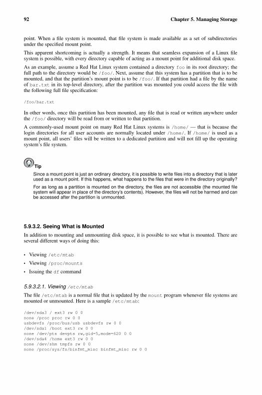
92 Chapter 5. Managing Storage
point. When a file system is mounted, that file system is made available as a set of subdirectoriesunder the specified mount point.
This apparent shortcoming is actually a strength. It means that seamless expansion of a Linux filesystem is possible, with every directory capable of acting as a mount point for additional disk space.
As an example, assume a Red Hat Linux system contained a directory foo in its root directory; thefull path to the directory would be /foo/. Next, assume that this system has a partition that is to bemounted, and that the partition’s mount point is to be /foo/. If that partition had a file by the nameof bar.txt in its top-level directory, after the partition was mounted you could access the file withthe following full file specification:
/foo/bar.txt
In other words, once this partition has been mounted, any file that is read or written anywhere underthe /foo/ directory will be read from or written to that partition.
A commonly-used mount point on many Red Hat Linux systems is /home/ — that is because thelogin directories for all user accounts are normally located under /home/. If /home/ is used as amount point, all users’ files will be written to a dedicated partition and will not fill up the operatingsystem’s file system.
Tip
Since a mount point is just an ordinary directory, it is possible to write files into a directory that is laterused as a mount point. If this happens, what happens to the files that were in the directory originally?
For as long as a partition is mounted on the directory, the files are not accessible (the mounted filesystem will appear in place of the directory’s contents). However, the files will not be harmed and canbe accessed after the partition is unmounted.
5.9.3.2. Seeing What is Mounted
In addition to mounting and unmounting disk space, it is possible to see what is mounted. There areseveral different ways of doing this:
• Viewing /etc/mtab
• Viewing /proc/mounts
• Issuing the df command
5.9.3.2.1. Viewing /etc/mtab
The file /etc/mtab is a normal file that is updated by the mount program whenever file systems aremounted or unmounted. Here is a sample /etc/mtab:
/dev/sda3 / ext3 rw 0 0none /proc proc rw 0 0usbdevfs /proc/bus/usb usbdevfs rw 0 0/dev/sda1 /boot ext3 rw 0 0none /dev/pts devpts rw,gid=5,mode=620 0 0/dev/sda4 /home ext3 rw 0 0none /dev/shm tmpfs rw 0 0none /proc/sys/fs/binfmt_misc binfmt_misc rw 0 0
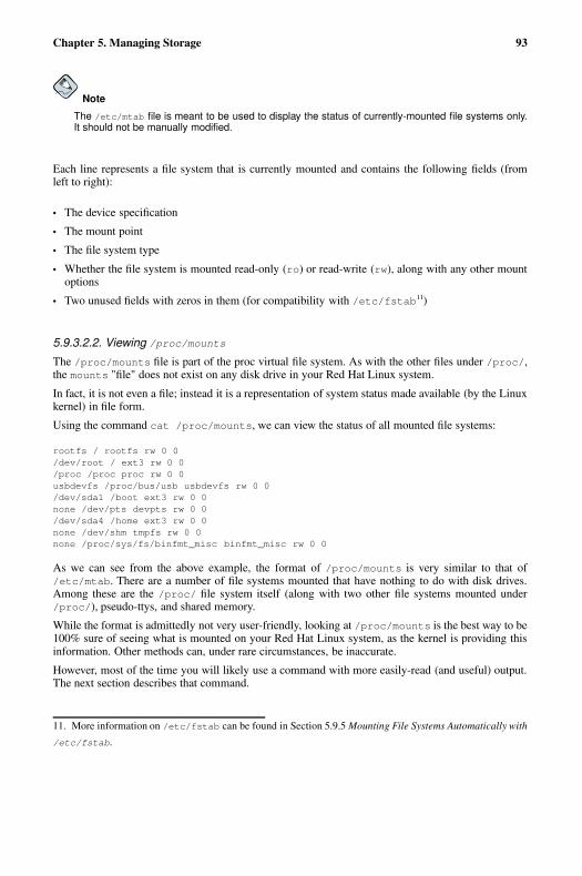
Chapter 5. Managing Storage 93
Note
The /etc/mtab file is meant to be used to display the status of currently-mounted file systems only.It should not be manually modified.
Each line represents a file system that is currently mounted and contains the following fields (fromleft to right):
• The device specification
• The mount point
• The file system type
• Whether the file system is mounted read-only (ro) or read-write (rw), along with any other mountoptions
• Two unused fields with zeros in them (for compatibility with /etc/fstab11)
5.9.3.2.2. Viewing /proc/mounts
The /proc/mounts file is part of the proc virtual file system. As with the other files under /proc/,the mounts "file" does not exist on any disk drive in your Red Hat Linux system.
In fact, it is not even a file; instead it is a representation of system status made available (by the Linuxkernel) in file form.
Using the command cat /proc/mounts, we can view the status of all mounted file systems:
rootfs / rootfs rw 0 0/dev/root / ext3 rw 0 0/proc /proc proc rw 0 0usbdevfs /proc/bus/usb usbdevfs rw 0 0/dev/sda1 /boot ext3 rw 0 0none /dev/pts devpts rw 0 0/dev/sda4 /home ext3 rw 0 0none /dev/shm tmpfs rw 0 0none /proc/sys/fs/binfmt_misc binfmt_misc rw 0 0
As we can see from the above example, the format of /proc/mounts is very similar to that of/etc/mtab. There are a number of file systems mounted that have nothing to do with disk drives.Among these are the /proc/ file system itself (along with two other file systems mounted under/proc/), pseudo-ttys, and shared memory.
While the format is admittedly not very user-friendly, looking at /proc/mounts is the best way to be100% sure of seeing what is mounted on your Red Hat Linux system, as the kernel is providing thisinformation. Other methods can, under rare circumstances, be inaccurate.
However, most of the time you will likely use a command with more easily-read (and useful) output.The next section describes that command.
11. More information on /etc/fstab can be found in Section 5.9.5 Mounting File Systems Automatically with
/etc/fstab.

94 Chapter 5. Managing Storage
5.9.3.2.3. The df Command
While using /etc/mtab or /proc/mounts lets you know what file systems are currently mounted,it does little beyond that. Most of the time you are more interested in one particular aspect of the filesystems that are currently mounted — the amount of free space on them.
For this, we can use the df command. Here is some sample output from df:
Filesystem 1k-blocks Used Available Use% Mounted on/dev/sda3 8428196 4280980 3719084 54% //dev/sda1 124427 18815 99188 16% /boot/dev/sda4 8428196 4094232 3905832 52% /homenone 644600 0 644600 0% /dev/shm
Several differences with /etc/mtab and /proc/mount are immediately obvious:
• An easy-to-read heading is displayed
• With the exception of the shared memory file system, only disk-based file systems are shown
• Total size, used space, free space, and percentage in use figures are displayed
That last point is probably the most important because every system administrator will eventuallyhave to deal with a system that has run out of free disk space. With df it is very easy to see where theproblem lies.
5.9.4. Network-Accessible Storage Under Red Hat LinuxThere are two major technologies used for implemented network-accessible storage under Red HatLinux:
• NFS
• SMB
The following sections describe these technologies.
5.9.4.1. NFS
As the name implies, the Network File System (more commonly known as NFS) is a file system thatmay be accessed via a network connection. With other file systems, the storage device must be directlyattached to the local system. However, with NFS this is not a requirement, making possible a varietyof different configurations, from centralized file system servers to entirely diskless computer systems.
However, unlike the other file systems, NFS does not dictate a specific on-disk format. Instead, itrelies on the server operating system’s native file system support to control the actual I/O to local diskdrive(s). NFS then makes the file system available to any operating system running a compatible NFSclient.
While primarily a Linux and UNIX technology, it is worth noting that NFS client implementationsexist for other operating systems, making NFS a viable technique to share files with a variety ofdifferent platforms.
The file systems an NFS server makes available to clients is controlled by the configuration file/etc/exports. For more information, see the exports(5) man page and the Red Hat Linux Cus-tomization Guide.
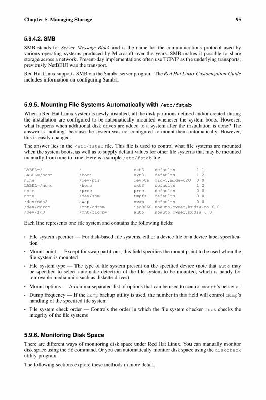
Chapter 5. Managing Storage 95
5.9.4.2. SMB
SMB stands for Server Message Block and is the name for the communications protocol used byvarious operating systems produced by Microsoft over the years. SMB makes it possible to sharestorage across a network. Present-day implementations often use TCP/IP as the underlying transports;previously NetBEUI was the transport.
Red Hat Linux supports SMB via the Samba server program. The Red Hat Linux Customization Guideincludes information on configuring Samba.
5.9.5. Mounting File Systems Automatically with /etc/fstab
When a Red Hat Linux system is newly-installed, all the disk partitions defined and/or created duringthe installation are configured to be automatically mounted whenever the system boots. However,what happens when additional disk drives are added to a system after the installation is done? Theanswer is "nothing" because the system was not configured to mount them automatically. However,this is easily changed.
The answer lies in the /etc/fstab file. This file is used to control what file systems are mountedwhen the system boots, as well as to supply default values for other file systems that may be mountedmanually from time to time. Here is a sample /etc/fstab file:
LABEL=/ / ext3 defaults 1 1LABEL=/boot /boot ext3 defaults 1 2none /dev/pts devpts gid=5,mode=620 0 0LABEL=/home /home ext3 defaults 1 2none /proc proc defaults 0 0none /dev/shm tmpfs defaults 0 0/dev/sda2 swap swap defaults 0 0/dev/cdrom /mnt/cdrom iso9660 noauto,owner,kudzu,ro 0 0/dev/fd0 /mnt/floppy auto noauto,owner,kudzu 0 0
Each line represents one file system and contains the following fields:
• File system specifier — For disk-based file systems, either a device file or a device label specifica-tion
• Mount point — Except for swap partitions, this field specifies the mount point to be used when thefile system is mounted
• File system type — The type of file system present on the specified device (note that auto maybe specified to select automatic detection of the file system to be mounted, which is handy forremovable media units such as diskette drives)
• Mount options — A comma-separated list of options that can be used to control mount’s behavior
• Dump frequency — If the dump backup utility is used, the number in this field will control dump’shandling of the specified file system
• File system check order — Controls the order in which the file system checker fsck checks theintegrity of the file systems
5.9.6. Monitoring Disk SpaceThere are different ways of monitoring disk space under Red Hat Linux. You can manually monitordisk space using the df command. Or you can automatically monitor disk space using the diskcheckutility program.
The following sections explore these methods in more detail.
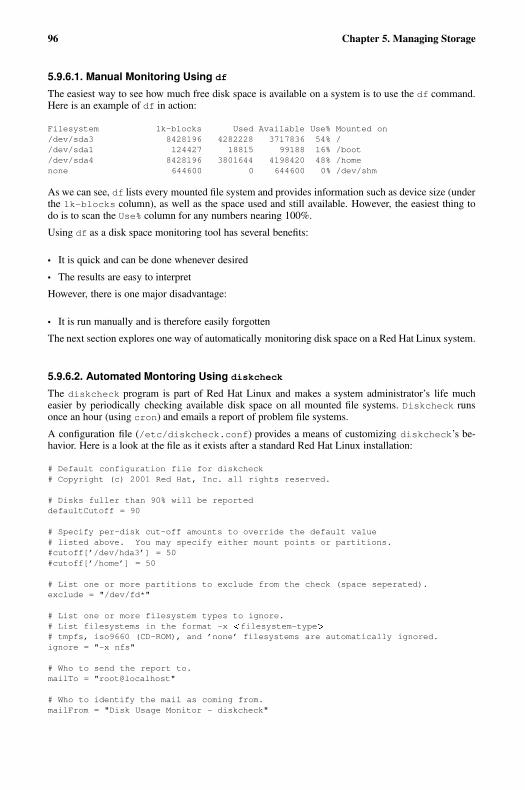
96 Chapter 5. Managing Storage
5.9.6.1. Manual Monitoring Using df
The easiest way to see how much free disk space is available on a system is to use the df command.Here is an example of df in action:
Filesystem 1k-blocks Used Available Use% Mounted on/dev/sda3 8428196 4282228 3717836 54% //dev/sda1 124427 18815 99188 16% /boot/dev/sda4 8428196 3801644 4198420 48% /homenone 644600 0 644600 0% /dev/shm
As we can see, df lists every mounted file system and provides information such as device size (underthe 1k-blocks column), as well as the space used and still available. However, the easiest thing todo is to scan the Use% column for any numbers nearing 100%.
Using df as a disk space monitoring tool has several benefits:
• It is quick and can be done whenever desired
• The results are easy to interpret
However, there is one major disadvantage:
• It is run manually and is therefore easily forgotten
The next section explores one way of automatically monitoring disk space on a Red Hat Linux system.
5.9.6.2. Automated Montoring Using diskcheck
The diskcheck program is part of Red Hat Linux and makes a system administrator’s life mucheasier by periodically checking available disk space on all mounted file systems. Diskcheck runsonce an hour (using cron) and emails a report of problem file systems.
A configuration file (/etc/diskcheck.conf) provides a means of customizing diskcheck’s be-havior. Here is a look at the file as it exists after a standard Red Hat Linux installation:
# Default configuration file for diskcheck# Copyright (c) 2001 Red Hat, Inc. all rights reserved.
# Disks fuller than 90% will be reporteddefaultCutoff = 90
# Specify per-disk cut-off amounts to override the default value# listed above. You may specify either mount points or partitions.#cutoff[’/dev/hda3’] = 50#cutoff[’/home’] = 50
# List one or more partitions to exclude from the check (space seperated).exclude = "/dev/fd*"
# List one or more filesystem types to ignore.# List filesystems in the format -x filesystem-type �# tmpfs, iso9660 (CD-ROM), and ’none’ filesystems are automatically ignored.ignore = "-x nfs"
# Who to send the report to.mailTo = "root@localhost"
# Who to identify the mail as coming from.mailFrom = "Disk Usage Monitor - diskcheck"
Chapter 5. Managing Storage 97
# Location of sendmail-like mailer program.mailProg = "/usr/sbin/sendmail"
The format of the diskcheck.conf file is straightforward and can be easily be changed to suit yourorganization’s needs.
While the comments in the configuration file are largely self-explanatory, there is one part of the filethat you should change immediately — the mailTo line. Because no system administrator shouldever use the root account for any task not requiring root-level access, it is far more preferable to havediskcheck notification email delivered to your personal account.
Here is a sample notification email:
From: [email protected]: Low disk space warningTo: [email protected]: Fri, 31 Jan 2003 13:40:15 -0500
Disk usage for pigdog.example.com:
/dev/hda4 (/) is 91% full -- 5.3G of 5.8G used, 495M remain
By using diskcheck, you can automatically perform a tedious task and rest assured that, if there is aproblem, you will know about it via email.
Tip
If you depend on diskcheck to alert you to disk space shortages, you should give some thought tothe possible impact of running out of disk space on the system to which your email is delivered. If, forexample, the file system holding your home directory is on a storage server, and used by others, if itwere to rapidly fill up, there might not be sufficient time for a notification email to be delivered beforethe file system is completely full. The result? No notification email, leaving you with the impressionthat everything is fine.
For more information on configuring diskcheck, see the chapter on gathering system information inthe Red Hat Linux Customization Guide.
5.9.7. Adding/Removing StorageWhile most of the steps required to add or remove storage depend more on the system hardware thanthe system software, there are aspects of the procedure that are specific to your operating environment.This section explores the steps necessary add and remove storage that are specific to Red Hat Linux.
5.9.7.1. Adding Storage
The process of adding storage to a Red Hat Linux system is relatively straightforward. Here are thesteps that are specific to Red Hat Linux:
• Partitioning
• Formatting the partition(s)
• Updating /etc/fstab
The following sections explore each step in more detail.
98 Chapter 5. Managing Storage
5.9.7.1.1. Partitioning
Once the disk drive has been installed, it is time to create one or more partitions to make the spaceavailable to Red Hat Linux.
There are several different ways of doing this:
• Using the command-line fdisk utility program
• Using parted, another command-line utility program
Although the tools may be different, the basic steps are the same. The commands necessary to performthese steps using fdisk are included:
1. Select the new disk drive (the drive’s name can be identified by following the device namingconventions outlined in Section 5.9.1 Device Naming Conventions). Using fdisk, this is doneby including the device name when you start fdisk:fdisk /dev/hda
2. View the disk drive’s partition table, to ensure that the disk drive to be partitioned is, in fact, thecorrect one. In our example, fdisk displays the partition table by using the p command:Command (m for help): p
Disk /dev/hda: 255 heads, 63 sectors, 1244 cylindersUnits = cylinders of 16065 * 512 bytes
Device Boot Start End Blocks Id System/dev/hda1 * 1 17 136521 83 Linux/dev/hda2 18 83 530145 82 Linux swap/dev/hda3 84 475 3148740 83 Linux/dev/hda4 476 1244 6176992+ 83 Linux
3. Delete any unwanted partitions that may already be present on the new disk drive. This is doneusing the d command in fdisk:Command (m for help): dPartition number (1-4): 1
The process would be repeated for all unneeded partitions present on the disk drive.
4. Create the new partition(s), being sure to specify the desired size and file system type. Usingfdisk, this is a two-step process — first, creating the partition (using the n command):Command (m for help): nCommand action
e extendedp primary partition (1-4)
p
Partition number (1-4): 1First cylinder (1-767): 1Last cylinder or +size or +sizeM or +sizeK: +512M
Second, by setting the file system type (using the t command):Command (m for help): tPartition number (1-4): 1Hex code (type L to list codes): 82
Partition type 82 represents a Linux swap partition.
Chapter 5. Managing Storage 99
5. Save your changes and exit the partitioning program. This is done in fdisk by using the wcommand:Command (m for help): w
Warning
When partitioning a new disk drive, it is vital that you are sure the disk drive you are about to partitionis the correct one. Otherwise, you may inadvertently partition a disk drive that is already in use, whichwill result in lost data.
Also make sure you have decided on the best partition size. Always give this matter serious thought,because changing it once the disk drive is in service will be much more difficult.
5.9.7.1.2. Formatting the Partition(s)
Formatting partitions under Red Hat Linux is done using the mkfs utility program. However, mkfsdoes not actually do the work of writing the file-system-specific information onto a disk drive; insteadit passes control to one of several other programs that actually create the file system.
This is the time to look at the mkfs. � fstype man page for the file system you have selected.For example, look at the mkfs.ext3 man page to see the options available to you when creatinga new ext3 file system. In general, the mkfs. � fstype programs provide reasonable defaults formost configurations; however here are some of the options that system administrators most commonlychange:
• Setting a volume label for later use in /etc/fstab
• On very large hard disks, setting a lower percentage of space reserved for the super-user
• Setting a non-standard block size and/or bytes per inode for configurations that must support eithervery large or very small files
• Checking for bad blocks before formatting
Once file systems have been created on all the appropriate partitions, the disk drive is properly con-figured for use.
Next, it is always best to double-check your work by manually mounting the partition(s) and makingsure everything is in order. Once everything checks out, it is time to configure your Red Hat Linuxsystem to automatically mount the new file system(s) whenever it boots.
5.9.7.1.3. Updating /etc/fstab
As outlined in Section 5.9.5 Mounting File Systems Automatically with /etc/fstab, you must addthe necessary line(s) to /etc/fstab in order to ensure that the new file system(s) are mounted when-ever the system reboots. Once you have updated /etc/fstab, test your work by issuing an "incom-plete" mount, specifying only the device or mount point. Something similar to one of the followingcommands will be sufficient:
mount /homemount /dev/hda3
(Replacing /home or /dev/hda3 with the mount point or device for your specific situation.)
If the appropriate /etc/fstab entry is correct, mount will obtain the missing information from itand complete the mount operation.
100 Chapter 5. Managing Storage
At this point you can be relatively confident that the new file system will be there the next time thesystem boots (although if you can afford a quick reboot, it would not hurt to do so — just to be sure).
5.9.7.2. Removing Storage
The process of removing storage from a Red Hat Linux system is relatively straightforward. Here arethe steps that are specific to Red Hat Linux:
• Remove the disk drive’s partitions from /etc/fstab
• Unmounting the disk drive’s active partitions
• Erase the contents of the disk drive
The following sections cover these topics in more detail.
5.9.7.2.1. Remove the Disk Drive’s Partitions From /etc/fstab
Using the text editor of your choice, remove the line(s) corresponding to the disk drive’s partition(s)from the /etc/fstab file. You can identify the proper lines by one of the following methods:
• Matching the partition’s mount point against the directories in the second column of /etc/fstab
• Matching the device’s file name against the file names in the first column of /etc/fstab
Tip
Be sure to look for any lines in /etc/fstab for swap partitions as well — they can be easily over-looked.
5.9.7.2.2. Terminating Access With unmount
Next, all access to the disk drive must be terminated. For partitions with active file systems on them,this is done using the unmount command. If a swap partition exists on the disk drive, it must be eitherbe deactivated with the swapoff command, or the system should be rebooted.
Unmounting partitions with the umount command requires you to specify either the device file name,or the partition’s mount point:
umount /dev/hda2umount /home
A partition can only be unmounted if it is not currently in use. If the partition cannot be unmountedwhile at the normal runlevel, boot into rescue mode and remove the partition’s /etc/fstab entry.
When using swapoff to disable swapping to a partition, you must specify the device file name repre-senting the swap partition:
swapoff /dev/hda4
If swapping to a swap partition cannot be disabled using swapoff, boot into rescue mode and removethe partition’s /etc/fstab entry.
Chapter 5. Managing Storage 101
5.9.7.2.3. Erase the Contents of the Disk Drive
Erasing the contents of a disk drive under Red Hat Linux is a straightforward procedure.
After unmounting all of the disk drive’s partitions, issue the following command (while logged in asroot):
badblocks -ws � device-name �
Where � device-name � represents the file name of the disk drive you wish to erase, excluding thepartition number. For example, /dev/hdb for the second ATA hard drive.
You will see the following output while badblocks runs:
Writing pattern 0xaaaaaaaa: doneReading and comparing: doneWriting pattern 0x55555555: doneReading and comparing: doneWriting pattern 0xffffffff: doneReading and comparing: doneWriting pattern 0x00000000: doneReading and comparing: done
Keep in mind that badblocks is actually writing four different data patterns to every block on thedisk drive. For large disk drives, this process can take a long time — quite often several hours.
Important
Many companies (and government agencies) have specific methods of erasing data from disk drivesand other data storage media. You should always be sure you understand and abide by these require-ments; in many cases there are legal ramifications if you fail to do so. The example above should inno way be considered the ultimate method of wiping a disk drive.
However, it is much more effective then using the rm command. That is because when you delete afile using rm it only marks the file as deleted — it does not erase the contents of the file.
5.9.8. Implementing Disk QuotasRed Hat Linux is capable of keeping track of disk space usage on a per-user and per-group basisthrough the use of disk quotas. The following section provides an overview of the features present indisk quotas under Red Hat Linux.
5.9.8.1. Some Background on Disk Quotas
Disk quotas under Red Hat Linux have the following features:
• Per-file-system implementation
• Per-user space accounting
• Per-group space accounting
• Tracks disk block usage
• Tracks disk inode usage
• Hard limits
102 Chapter 5. Managing Storage
• Soft limits
• Grace periods
The following sections describe each feature in more detail.
5.9.8.1.1. Per-File-System Implementation
Disk quotas under Red Hat Linux can be used on a per-file-system basis. In other words, disk quotascan be enabled or disabled for each file system individually.
This provides a great deal of flexibility to the system administrator. For example, if the /home/ direc-tory was on its own file system, disk quotas could be enabled there, enforcing equitable disk usage byall users. However the root file system could be left without disk quotas, eliminating the complexityof maintaining disk quotas on a file system where only the operating system itself resides.
5.9.8.1.2. Per-User Space Accounting
Disk quotas can perform space accounting on a per-user basis. This means that each user’s spaceusage is tracked individually. It also means that any limitations on usage (which are discussed in latersections) are also done on a per-user basis.
Having the flexibility of tracking and enforcing disk usage for each user individually makes it possiblefor a system administrator to assign different limits to individual users, according to their responsibil-ities and storage needs.
5.9.8.1.3. Per-Group Space Accounting
Disk quotas can also perform disk usage tracking on a per-group basis. This is ideal for those organi-zations that use groups as a means of combining different users into a single project-wide resource.
By setting up group-wide disk quotas, the system administrator can more closely manage storageutilization by giving individual users only the disk quota they require for their personal use, whilesetting larger disk quotas that would be more appropriate for multi-user projects. This can be a greatadvantage to those organizations that use a "chargeback" mechanism to assign data center costs tothose departments and teams that use data center resources.
5.9.8.1.4. Tracks Disk Block Usage
Disk quotas track disk block usage. Because all the data stored on a file system is stored in blocks,disk quotas are able to directly correlate the files created and deleted on a file system with the amountof storage those files take up.
5.9.8.1.5. Tracks Disk Inode Usage
In addition to tracking disk block usage, disk quotas also can track inode usage. Under Red Hat Linux,inodes are used to store various parts of the file system, but most importantly, inodes hold informationfor each file. Therefore, by tracking (and controlling) inode usage, it is possible to control the creationof new files.
5.9.8.1.6. Hard Limits
A hard limit is the absolute maximum number of disk blocks (or inodes) that can be temporarily usedby a user (or group). Any attempt to use a single block or inode above the hard limit will fail.
Chapter 5. Managing Storage 103
5.9.8.1.7. Soft Limits
A soft limit is the maximum number of disk blocks (or inodes) that can be permanently used by a user(or group).
The soft limit is set below the hard limit. This allows users to temporarily exceed their soft limit,permitting them to finish whatever they were doing, and giving them some time in which to go throughtheir files and trim back their usage to below their soft limit.
5.9.8.1.8. Grace Periods
As stated earlier, any disk usage above the soft limit is temporary. It is the grace period that determinesthe length of time that a user (or group) can extend their usage beyond their soft limit and toward theirhard limit.
If a user continues to use more than the soft limit and the grace period expires, no additional diskusage will be permitted until the user (or group) has reduced their usage to a point below the softlimit.
The grace period can be expressed in seconds, minutes, hours, days, weeks, or months, giving thesystem administrator a great deal of freedom in determining how much time to give users to get theirdisk usages below their soft limits.
5.9.8.2. Enabling Disk Quotas
Note
The following sections provide a brief overview of the steps necessary to enable disk quotas underRed Hat Linux. For a more in-depth treatment of this subject, see the chapter on disk quotas in theRed Hat Linux Customization Guide.
In order to use disk quotas, you must first enable them. This process involves several steps:
1. Modifying /etc/fstab
2. Remounting the file system(s)
3. Running quotacheck
4. Assigning quotas
The /etc/fstab file controls the mounting of file systems under Red Hat Linux. Because disk quotasare implemented on a per-file-system basis, there are two options — usrquota and grpquota— thatmust be added to that file in order to enable disk quotas. The usrquota option enables user-baseddisk quotas, while the grpquota option enables group-based quotas. One or both of these optionsmay be enabled by placing them in the options field for the desired file system.
The affected file system(s) then must be unmounted and remounted in order for the disk quota-relatedoptions to take affect.
Next, the quotacheck command is used to create the disk quota files and to collect the currentusage information from already existing files. The disk quota files (named aquota.user andaquota.group for user- and group-based quotas) contain the necessary quota-related informationand reside in the file system’s root directory.
To assign disk quotas, the edquota command is used.
104 Chapter 5. Managing Storage
This utility program uses a text editor to display the quota information for the user or group specifiedas part of the edquota command. Here is an example:
Disk quotas for user matt (uid 500):Filesystem blocks soft hard inodes soft hard/dev/md3 6618000 0 0 17397 0 0
This shows that user matt is currently using over 6GB of disk space, and over 17,000 inodes. No quota(soft or hard) have yet been set for either disk blocks or inodes, meaning that there is no limit to thedisk space and inodes that this user can currently use..
Using the text editor displaying the disk quota information, the system administrator can then modifythe soft and hard limits as desired:
Disk quotas for user matt (uid 500):Filesystem blocks soft hard inodes soft hard/dev/md3 6618000 6900000 7000000 17397 0 0
In this example, user matt has been given a soft limit of 6.9GB and a hard limit of 7GB. No soft orhard limit on inodes has been set for this user.
Tip
The edquota program can also be used to set the per-file-system grace period by using the -t option.
5.9.8.3. Managing Disk Quotas
There is little actual management required to support disk quotas under Red Hat Linux. Essentially,all that is required is:
• Generating disk usage reports at regular intervals (and following up with users that seem to behaving trouble effectively managing their allocated disk space)
• Making sure that the disk quotas remain accurate
Creating a disk usage report entails running the repquota utility program. Using the commandrepquota /home produces this output:
*** Report for user quotas on device /dev/md3Block grace time: 7days; Inode grace time: 7days
Block limits File limitsUser used soft hard grace used soft hard grace----------------------------------------------------------------------root -- 32836 0 0 4 0 0matt -- 6618000 6900000 7000000 17397 0 0
More information about repquota can be found in the Red Hat Linux Customization Guide, in thechapter on disk quotas.
Whenever a file system is not unmounted cleanly (due to a system crash, for example), it is necessaryto run quotacheck. However, many system administrators recommend running quotacheck on aregular basis, even if the system has not crashed.
The process is similar to the initial use of quotacheckwhen enabling disk quotas. Here is an examplequotacheck command:
quotacheck -avug
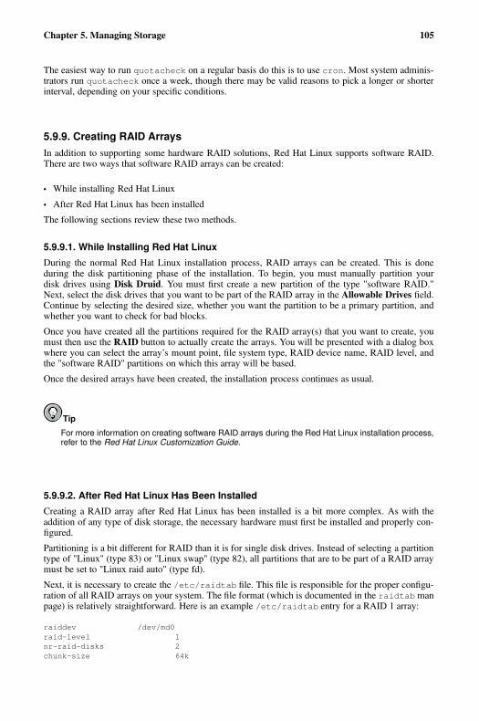
Chapter 5. Managing Storage 105
The easiest way to run quotacheck on a regular basis do this is to use cron. Most system adminis-trators run quotacheck once a week, though there may be valid reasons to pick a longer or shorterinterval, depending on your specific conditions.
5.9.9. Creating RAID ArraysIn addition to supporting some hardware RAID solutions, Red Hat Linux supports software RAID.There are two ways that software RAID arrays can be created:
• While installing Red Hat Linux
• After Red Hat Linux has been installed
The following sections review these two methods.
5.9.9.1. While Installing Red Hat Linux
During the normal Red Hat Linux installation process, RAID arrays can be created. This is doneduring the disk partitioning phase of the installation. To begin, you must manually partition yourdisk drives using Disk Druid. You must first create a new partition of the type "software RAID."Next, select the disk drives that you want to be part of the RAID array in the Allowable Drives field.Continue by selecting the desired size, whether you want the partition to be a primary partition, andwhether you want to check for bad blocks.
Once you have created all the partitions required for the RAID array(s) that you want to create, youmust then use the RAID button to actually create the arrays. You will be presented with a dialog boxwhere you can select the array’s mount point, file system type, RAID device name, RAID level, andthe "software RAID" partitions on which this array will be based.
Once the desired arrays have been created, the installation process continues as usual.
Tip
For more information on creating software RAID arrays during the Red Hat Linux installation process,refer to the Red Hat Linux Customization Guide.
5.9.9.2. After Red Hat Linux Has Been Installed
Creating a RAID array after Red Hat Linux has been installed is a bit more complex. As with theaddition of any type of disk storage, the necessary hardware must first be installed and properly con-figured.
Partitioning is a bit different for RAID than it is for single disk drives. Instead of selecting a partitiontype of "Linux" (type 83) or "Linux swap" (type 82), all partitions that are to be part of a RAID arraymust be set to "Linux raid auto" (type fd).
Next, it is necessary to create the /etc/raidtab file. This file is responsible for the proper configu-ration of all RAID arrays on your system. The file format (which is documented in the raidtab manpage) is relatively straightforward. Here is an example /etc/raidtab entry for a RAID 1 array:
raiddev /dev/md0raid-level 1nr-raid-disks 2chunk-size 64k
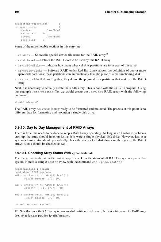
106 Chapter 5. Managing Storage
persistent-superblock 1nr-spare-disks 0
device /dev/hda2raid-disk 0device /dev/hdc2raid-disk 1
Some of the more notable sections in this entry are:
• raiddev — Shows the special device file name for the RAID array12
• raid-level — Defines the RAID level to be used by this RAID array
• nr-raid-disks — Indicates how many physical disk partitions are to be part of this array
• nr-spare-disks — Software RAID under Red Hat Linux allows the definition of one or morespare disk partitions; these partitions can automatically take the place of a malfunctioning disk
• device, raid-disk — Together, they define the physical disk partitions that make up the RAIDarray
Next, it is necessary to actually create the RAID array. This is done with the mkraid program. Usingour example /etc/raidtab file, we would create the /dev/md0 RAID array with the followingcommand:
mkraid /dev/md0
The RAID array /dev/md0 is now ready to be formatted and mounted. The process at this point is nodifferent than for formatting and mounting a single disk drive.
5.9.10. Day to Day Management of RAID ArraysThere is little that needs to be done to keep a RAID array operating. As long as no hardware problemscrop up, the array should function just as if it were a single physical disk drive. However, just as asystem administrator should periodically check the status of all disk drives on the system, the RAIDarrays’ status should be checked as well.
5.9.10.1. Checking Array Status With /proc/mdstat
The file /proc/mdstat is the easiest way to check on the status of all RAID arrays on a particularsystem. Here is a sample mdstat (view with the command cat /proc/mdstat):
Personalities : [raid1]read_ahead 1024 sectorsmd1 : active raid1 hda3[0] hdc3[1]
522048 blocks [2/2] [UU]
md0 : active raid1 hda2[0] hdc2[1]4192896 blocks [2/2] [UU]
md2 : active raid1 hda1[0] hdc1[1]128384 blocks [2/2] [UU]
unused devices: � none �
12. Note that since the RAID array is composed of partitioned disk space, the device file name of a RAID array
does not reflect any partition-level information.
Chapter 5. Managing Storage 107
On this system, there are three RAID arrays (all RAID 1). Each RAID array has its own section in/proc/mdstat and contains the following information:
• The RAID array device name (not including the /dev/ part)
• The status of the RAID array
• The RAID array’s RAID level
• The physical partitions that currently make up the array (followed by the partition’s array unitnumber)
• The size of the array
• The number of configured devices versus the number of operative devices in the array
• The status of each configured device in the array (U meaning the device is OK, and _ indicating thatthe device has failed)
5.9.10.2. Rebuilding a RAID array with raidhotadd
Should /proc/mdstat show that a problem exists with one of the RAID arrays, the raidhotaddutility program should be used to rebuild the array. Here are the steps that would need to be performed:
1. Determine which disk drive contains the failed partition
2. Correct the problem that caused the failure (most likely by replacing the drive)
3. Partition the new drive so that the partitions on it are identical to those on the other drive(s) inthe array
4. Issue the following command:raidhotadd � raid-device ��� disk-partition �
5. Monitor /proc/mdstat to watch the rebuild take place
Tip
Here is a command that can be used to watch the rebuild as it takes place:
watch -n1 cat /proc/mdstat
This command displays the contents of /proc/mdstat, updating it every second.
5.10. Additional ResourcesThis section includes various resources that can be used to learn more about storage technologies andthe Red Hat Linux-specific subject matter discussed in this chapter.
108 Chapter 5. Managing Storage
5.10.1. Installed DocumentationThe following resources are installed in the course of a typical Red Hat Linux installation, and canhelp you learn more about the subject matter discussed in this chapter.
• exports(5) man page — NFS configuration file format.
• fstab(5) man page — File system information configuration file format.
• swapoff(8) man page — Disable swap partitions.
• df(1) man page — Report disk space usage on mounted file systems.
• fdisk(8) man page — Partition table maintenance utility program.
• mkfs(8), mke2fs(8) man pages — File system creation utility programs.
• badblocks(8) man page — Test a device for bad blocks.
• quotacheck(8) man page — Check disk block and inode usage for users and groups and option-ally create disk quota files.
• edquota(8) man page — Disk quota maintenance utility program.
• repquota(8) man page — Disk quota reporting utility program.
• raidtab(5) man page — Software RAID configuration file format.
• mkraid(8) man page — Software RAID array creation utility program.
5.10.2. Useful Websites
• http://www.pcguide.com/ — A good site for all kinds of information on various storage technolo-gies.
• http://www.tldp.org/ — The Linux Documentation Project has HOWTOs and mini-HOWTOs thatprovide good overviews of storage technologies as they relate to Linux.
5.10.3. Related BooksThe following books discuss various issues related to storage and are good resources for Red HatLinux system administrators.
• The Red Hat Linux Installation Guide; Red Hat, Inc. — Contains instructions on partitioning harddrives during the Red Hat Linux installation process as well as an overview of disk partitions.
• The Red Hat Linux Getting Started Guide; Red Hat, Inc. — Provides an introductory view into themanagement of files and directories and using removable mass storage devices.
• The Red Hat Linux Reference Guide; Red Hat, Inc. — Contains detailed information on the direc-tory structure used in Red Hat Linux and an overview of NFS.
• The Red Hat Linux Customization Guide; Red Hat, Inc. — Includes chapters on file systems, RAID,partitioning, disk quotas, NFS, and Samba.
• Linux System Administration: A User’s Guide by Marcel Gagne; Addison Wesley Professional —Contains information on user and group permissions, file systems and disk quota, NFS and Samba.
• Linux Performance Tuning and Capacity Planning by Jason R. Fink and Matthew D. Sherer; Sams— Contains information on disk, RAID, and NFS performance.
• Linux Administration Handbook by Evi Nemeth, Garth Snyder, and Trent R. Hein; Prentice Hall —Contains information on file systems, handling disk drives, NFS, and Samba.
Chapter 6.
Managing User Accounts and Resource Access
Managing user accounts and groups is an essential part of system administration within an organiza-tion. But to do this effectively, a good system administrator must first understand what user accountsand groups are and how they work.
The primary reason for user accounts is to verify the identity of each individual using a computersystem. A secondary (but still important) reason for user accounts is to permit the per-individualtailoring of resources and access privileges.
Resources can include files, directories, and devices. Controlling access to these resources is a largepart of a system administrator’s daily routine; often the access to a resource is controlled by groups.Groups are logical constructs that can be used to cluster user accounts together for a common purpose.For example, if an organization has multiple system administrators, they can all be placed in onesystem administrator group. The group can then be given permission to access key system resources.In this way, groups can be a powerful tool for managing resources and access.
The following sections discuss user accounts and groups in more detail.
6.1. Managing User AccountsAs stated earlier, user accounts are the method by which an individual is identified and authenticatedto the system. User accounts have several different components to them. First, there is the username.The password is next, followed by the access control information.
The following sections explore each of these components in more detail.
6.1.1. The UsernameFrom the system’s standpoint, the username is the answer to the question, "who are you?" As such,usernames have one major requirement — they must be unique. In other words, each user must havea username that is different from all other usernames on that system.
Because of this requirement, it is vital to determine — in advance — how usernames will be created.Otherwise, you will be in the position of being forced to react each time a new user requests anaccount.
What you need is a naming convention for your user accounts.
6.1.1.1. Naming Conventions
By creating a naming convention for usernames, you can save yourself a great deal of trouble. Insteadof making up names as you go along (and finding it harder and harder to come up with a reasonablename), you do some work up-front and devise a convention that will be used for all subsequent useraccounts. Your naming convention can be very simple, or the description alone could take severalpages to document.
The exact nature of your naming convention should take several factors into account:
• The size of your organization
• The structure of your organization
• The nature of your organization
110 Chapter 6. Managing User Accounts and Resource Access
The size of your organization matters, as it dictates how many users your naming convention mustsupport. For example, a very small organization might be able to have everyone use their first name.For a much larger organization this naming convention would not work.
An organization’s structure can also have a bearing on the most appropriate naming convention. Fororganizations with a strictly-defined structure it might be appropriate to include elements of that struc-ture in the naming convention. For example, you could include your organization’s departmental codesas part of each username.
The overall nature of your organization may also mean that some naming conventions are more ap-propriate than others. An organization that deals with highly-classified data might choose a namingconvention that does away with any personally-identifiable ties between the individual and their name.In such an organization, Maggie McOmie’s username might be LUH3417.
Here are some naming conventions that other organizations have used:
• First name (john, paul, george, etc.)
• Last name (smith, jones, brown, etc.)
• First initial, followed by last name (jsmith, pjones, gbrown, etc.
• Department code followed by user’s last name (029smith, 454jones, 191brown, etc.)
Tip
Be aware that if your naming convention includes appending different data together to form a user-name, the potential exists that the result might be offensive or humorous. Therefore, even if you haveautomated username creation, it is wise to have some sort of review process in place.
One thing in common with the naming conventions described here is that it is possible that eventuallythere will be two individuals that, according to the naming convention, should be given the sameusername. This is known as a collision. Because each username must be unique, it is necessary toaddress the issue of collisions. The following section does this.
6.1.1.1.1. Dealing with Collisions
Collisions are a fact of life — no matter how you try, you will eventually find yourself with a collisionon your hands. You must plan for collisions in your naming convention. There are several ways thiscan be done:
• Adding sequence numbers to the colliding username (smith, smith1, smith2, etc.)
• Adding user-specific data to the colliding username (smith, esmith, eksmith, etc.)
• Adding organizational information to the colliding username (smith, smith029, smith454, etc.)
Having some method of resolving collisions is a necessary part of any naming convention. How-ever, it does make it more difficult for someone outside the organization to accurately determine anindividual’s username. Therefore, the downside of most naming conventions is that the occasionalmisdirected email becomes more likely.
Chapter 6. Managing User Accounts and Resource Access 111
6.1.1.2. Dealing with Name Changes
If your organization uses a naming convention that is based on each user’s name, it is a fact of lifethat you will eventually have to deal with name changes. The most common situation is one where awoman marries (or divorces) and changes her name, but this is not the only time a system administratorwill be asked to change a username. Even if a person’s actual name does not change, a change inusername may from time to time be requested. The reasons can range from the user not being satisfiedwith the username to the user being a senior official in your organization and willing to use theirinfluence to obtain a "more appropriate" username.
No matter what the reason, there are several issues to keep in mind when changing a username:
• Make the change to all affected systems
• Keep any underlying user identification constant
• Change the ownership of all files and other user-specific resources (if necessary)
• Handle email-related issues
First and foremost, it is important to make sure that the new username is propagated to all systemswhere the original username was in use. Otherwise, any operating system function that relies on theusername will work on some systems and not on others. Certain operating systems use access controltechniques based on usernames; such systems are particularly vulnerable to problems stemming froma changed username.
Many operating systems use some sort of user identification number for most user-specific processing.To minimize the problems stemming from a username change, try to keep this identification numberconstant between the new and the old username. Failure to do so often results in a scenario where theuser can no longer access files and other resources that they had previously owned under their originalusername.
If the user identification number must be changed, it is necessary to change the ownership for all filesand user-specific resources to reflect the new user identification. This can be an error-prone process,as it seems that there is always something in some forgotten corner of a system that ends up beingoverlooked.
Issues related to email are probably the one area where a username change is the most difficult. Thereason for this is that unless steps are taken to counteract it, email addressed to the old username willnot be delivered to the new username.
Unfortunately, the issues surrounding the impact of username changes on email are multi-dimensional.At its most basic, a username change means that people no longer know the correct username forthe person. At first glance, this might not seem to be such a problem — notify everyone in yourorganization of the change. But what about anyone outside of your organization that has sent thisperson email? How will they be notified? And what about mailing lists (both internal and external)?How can they be updated?
There is no easy answer to these questions. The best answer may be one of creating an email aliassuch that all email sent to the old username will automatically be forwarded to the new username. Theuser can then be urged to alert anyone who sends them email that their username has changed. Astime goes on, fewer and fewer email messages will be delivered using the alias; eventually the aliascan be removed.
While the use of aliases, at some level, perpetuates an incorrect assumption (that the user now knownas esmith is still known as ejones), it is the only way to guarantee that email will reach the properperson.
112 Chapter 6. Managing User Accounts and Resource Access
Important
If you use email aliases, be sure you take whatever steps are necessary to protect the old usernamefrom potential reuse. If you do not do this, and a new user receives the old username, email delivery(for either the original user or the new user) will be disrupted. The exact nature of the disruptiondepends on how email delivery is implemented on your operating system, but the two most likelysymptoms are:
• The new user never receives any email — it all goes to the original user.
• The original user suddenly stops receiving any email — it all goes to the new user.
6.1.2. PasswordsIf the username provides an answer to the question, "who are you?", the password is the response tothe demand that inevitably follows:
"Prove it!"
In more formal terms, a password provides a means of proving the authenticity of a person’s claim tobe the user indicated by the username. The effectiveness of a password-based authentication schemerelies heavily on several aspects of the password:
• The secrecy of the password
• The resistance of the password to guessing
• The resistance of the password to a brute-force attack
Passwords that adequately address these issues are said to be strong, while those that fail to addressone or more of these issues is said to be weak. Creating strong passwords is important for the securityof the organization, as strong passwords are less likely to be discovered or guessed. There are twooptions available to enforce the use of strong passwords:
• The system administrator can create passwords for all users.
• The system administrator can let the users create their own passwords, while verifying that thepasswords are acceptably strong.
Creating passwords for all users ensures that the passwords are strong, but it becomes a daunting taskas the organization grows. It also increases the risk of users writing their passwords down.
For these reasons, most system administrators prefer to have their users create their own passwords.However, a good system administrator takes steps to verify that the passwords are strong.
For guidelines on creating strong passwords, see the chapter titled Workstation Security in the RedHat Linux Security Guide.
The need for passwords to be kept secret should an ingrained part of every system administrator’smindset. However, this point is often lost on many users. In fact, many users do not even understandthe difference between usernames and passwords. Given this unfortunate fact of life, it is vital thatsome amount of user education be undertaken, so that your users understand that their passwordshould be kept as secret as their paycheck.
Passwords should be as difficult as possible to guess. A strong password is one that an attacker wouldnot be able to guess, even if the attacker knew the user well.
A brute-force attack on a password entails methodically trying (usually via a program known as apassword-cracker) every possible combination of characters in the hopes that the proper password

Chapter 6. Managing User Accounts and Resource Access 113
will eventually be found. A strong password should be constructed in such a way as to make thenumber of potential passwords that must be tested very large, forcing the attacker to take a long timesearching for the password.
Strong and weak passwords are explored in more detail in the following sections.
6.1.2.1. Weak Passwords
As stated earlier, a weak password fails one of these three tests:
• It is secret
• It is resistant to being guessed
• It is resistant to a brute-force attack
The following sections show how passwords can be weak.
6.1.2.1.1. Short Passwords
A password that is short is weak because it much more susceptible to a brute-force attack. To illustratethis, consider the following table, where the number of potential passwords that would have to betested in a brute-force attack is shown. (The passwords are assumed to consist only of lower-caseletters.)
Password Length Potential Passwords
1 26
2 676
3 17,576
4 456,976
5 11,881,376
6 308,915,776
Table 6-1. Password Length Versus the Number of Potential Passwords
As you can see, the number of possible passwords increases dramatically as the length increases.
Note
Even though this table ends at six characters, this should not be construed as recommending thatsix-character passwords are sufficiently long for good security. In general, the longer the password,the better.
6.1.2.1.2. Limited Character Set
The number of different characters that can comprise a password has a large impact on the ability ofan attacker to conduct a brute-force attack. For example, instead of the 26 different characters that canbe used in a lower-case-only password, what if we also used digits? That would mean each characterin a password could be one of 36 characters instead of just one of 26. In the case of a six-characterpassword, this increases the number of possible passwords from 308,915,776 to 2,176,782,336.
114 Chapter 6. Managing User Accounts and Resource Access
There is still more that can be done. If we also include mixed-case alphanumeric passwords (forthose operating systems that support it), the number of possible six-character passwords increases to56,800,235,584. Adding other characters (such as punctuation marks) further increases the number ofpossible passwords, making a brute-force attack that much more difficult.
However, one point to keep in mind is that not every attack against a password is a brute-force attack.The following sections describe other attributes that can make a weak password.
6.1.2.1.3. Recognizable Words
Many attacks against passwords are based on the fact that people are most comfortable with pass-words they can remember. And for most people, passwords that are memorable are passwords thatcontain words. Therefore, most password attacks are dictionary-based. In other words, the attackeruses dictionaries of words in an attempt to find the word or words that comprise a password.
Note
Many dictionary-based password attack programs use dictionaries from multiple languages. There-fore, you should not feel that you have a strong password just because you have used non-Englishwords in your password.
6.1.2.1.4. Personal Information
Passwords that contain personal information (the name or birth date of a loved one, a pet, or a personalidentification number) may or may not be picked up by a dictionary-based password attack. However,if the attacker knows you personally (or is sufficiently motivated to research your personal life), theymight be able to guess your password with little or no difficulty.
In addition to dictionaries, many password-crackers also include common names, dates, and othersuch information in their search for passwords. Therefore, even if the attacker does not know thatyour dog is named Gracie, they could still find out that your password is "mydogisgracie", with agood password-cracker.
6.1.2.1.5. Simple Word Tricks
Using any of the previously discussed information as the basis for a password, but reversing the char-acter order will not turn a weak password into a strong password. Most password-crackers performsuch tricks on possible passwords. This includes substituting certain numbers for letters in commonwords. Here are some examples:
• drowssaPdaB1
• R3allyP00r
6.1.2.1.6. The Same Password for Multiple Systems
Even if you have a password that is strong, it is a bad idea to use the exact same password on more thanone system. Obviously little can be done if the systems are configured to use a central authenticationserver of some kind, but in every other instance, different passwords should be used for each system.
Chapter 6. Managing User Accounts and Resource Access 115
6.1.2.1.7. Passwords on Paper
Another way to turn a strong password into a weak one is to write it down. By putting a password onpaper, you no longer have a secrecy problem, you have a physical security problem — now you mustkeep a piece of paper secure. Therefore, writing down a password is never a good idea.
However, some organizations have a legitimate need for written passwords. For example, some or-ganizations have written passwords as part of a procedure to recover from the loss of key personnel(such as system administrators). In these instances, the paper containing the passwords is stored ina physically-secure location that requires multiple people to cooperate in order to get access to thepaper. Vaults with multiple locks and bank safe deposit boxes are often used.
Any organization that explores this method of storing passwords for emergency purposes should beaware that the existence of written passwords adds an element of risk to their systems’ security, nomatter how securely the written passwords may be stored. This is particularly true if it is generallyknown that the passwords are written down (and where they are stored).
Unfortunately, written passwords are often not part of a recovery plan and are not stored in a vault,but are passwords for ordinary users, and are stored in the following places:
• In a desk drawer (locked or unlocked)
• Below a keyboard
• In a wallet
• Taped to the side of a monitor
None of these locations are proper places for a written password.
6.1.2.2. Strong Passwords
We have seen what weak passwords are like; the following sections describe features that all strongpasswords possess.
6.1.2.2.1. Longer Passwords
The longer a password is, the less likely it is that a brute-force attack will succeed. Therefore, if youroperating system supports it, set relatively large minimum password lengths for your users.
6.1.2.2.2. Expanded Character Set
Encourage the use of mixed-case, alphanumeric passwords, and strongly encourage the addition of atleast one non-alphanumeric character to all passwords:
• t1Te-Bf,te
• Lb@lbhom
6.1.2.2.3. Memorable
A password is strong only if it can be remembered. However, being memorable and being easilyguessed too often go hand-in-hand. Therefore, give your user community some tips on the creation ofmemorable passwords that cannot be easily guessed.
For example, take a favorite saying or phrase, and use the first letters of each word as the starting pointin the creation of a new password. The result is memorable (because the phrase on which it is basedis itself memorable), yet the result contains no words.
116 Chapter 6. Managing User Accounts and Resource Access
Note
Keep in mind that just using the first letters of each word in a phrase is not sufficient to make astrong password. Always be sure to increase the password’s character set by including mixed-casealphanumeric characters and at least one special character as well.
6.1.2.3. Password Aging
If at all possible, implement password aging at your organization. Password aging is a feature (avail-able in many operating systems) that sets limits on the time that a given password will be consideredvalid. At the end of a password’s lifetime, the user will be prompted to enter a new password, whichcan then be used until, it too, expires.
The key question regarding password aging that many system administrators face is that of the pass-word lifetime. What should it be?
There are two diametrically-opposed issues at work with respect to password lifetime:
• User convenience
• Security
On one extreme, a password lifetime of 99 years would present very little (if any) user inconvenience.However, it would provide very little (if any) security enhancement.
On the other extreme, a password lifetime of 99 minutes would be a large inconvenience to your users.However, security would be greatly enhanced.
The idea is to find a balance between your users’ desired for convenience and your organization’sneed for security. For most organizations, password lifetimes in the weeks-to-months range are mostcommon.
6.1.3. Access Control InformationAlong with a username and password, user accounts also contain access control information. Thisinformation takes on different forms according to the operating system being used. However, thetypes of information often include:
• System-wide user-specific identification
• System-wide group-specific identification
• Lists of additional groups/capabilities to which the user is a member
• Default access information to be applied to all user-created files and resources
In some organizations, a user’s access control information may never need to be touched. This is mostoften the case with standalone, personal workstations, for example. Other organizations, particularlythose that make extensive use of network-wide resource sharing among different groups of users,require that a user’s access control information be extensively modified.
The workload required to properly maintain your users’ access control information varies accordingto how extensively your organization uses your operating system’s access control features. While it isnot a bad thing to rely so heavily on these features (in fact, it may be unavoidable), it does mean thatyour system environment will require more effort to maintain, and that every user account will havemore ways in which it can be mis-configured.
Chapter 6. Managing User Accounts and Resource Access 117
Therefore, if your organization requires this kind of environment, you should make a point of docu-menting the exact steps required to create and correctly configure a user account. In fact, if there aredifferent types of user accounts, you should document each one (creating a new finance user account,a new operations user account, etc.).
6.1.4. Managing Accounts and Resource Access Day-to-DayAs the old saying goes, the only constant is change. It is no different when dealing with your usercommunity. People will come, people will go, and people will move from one set of responsibilitiesto another. Therefore, system administrators must be able to respond to the changes that are a normalpart of day-to-day life in your organization.
6.1.4.1. New Hires
When a new person joins your organization, they are normally given access to various resources(depending on their responsibilities). They may be given a place to work, a phone, and a key to thefront door.
They may also be given access to one or more of the computers in your organization. As a systemadministrator, it is your responsibility to see that this is done promptly and appropriately. How shouldyou do this?
Before you can do anything, you must first be aware of the new person’s arrival. This is handleddifferently in various organizations. Here are some possibilities:
• Create a procedure where your organization’s personnel department notifies you when a new personarrives.
• Create a form that the person’s supervisor can fill out and use to request an account for the newperson.
Different organizations require different approaches. However it is done, it is vital that you have ahighly-reliable process that can alert you to any account-related work that needs to be done.
6.1.4.2. Terminations
The fact that people will be leaving your organization is a given. Sometimes it will be under happycircumstances and sometimes it will be under unhappy circumstances. In either case, it is vital thatyou are made aware of the situation so that you can take the appropriate actions.
At the very least, the appropriate actions should include:
• Disabling the user’s access to all systems and related resources (usually by changing/locking theuser’s password)
• Backing up the user’s files, in case they contain something that is needed at a later time
• Coordinating access to the user’s files by the user’s manager
The top priority is to secure your systems against the newly-terminated user. This is particularlyimportant if the user was terminated under conditions that could leave the user feeling malice towardyour organization. However, even if the circumstances are not quite so dire, it is in your organization’sbest interest for you to quickly and reliably disable access by the newly-terminated person.
This indicates the need for a process that alerts you to all terminations — preferably even before theactual termination takes place. This implies that you should work with your organization’s personneldepartment to ensure that you are alerted to any upcoming terminations.
118 Chapter 6. Managing User Accounts and Resource Access
Tip
When handling system "lock-downs" in response to terminations, proper timing is important. If thelock-down takes place after the termination process has been completed, there is the potential forunauthorized access by the newly-terminated person. On the other hand, if the lock-down takesplace before the termination process has been initiated, it could alert the person to their impendingtermination, and make the process more difficult for all parties.
The termination process is usually initiated by a meeting between the person to be terminated, theperson’s manager, and a representative of your organization’s personnel department. Therefore,putting a process in place that alerts you to the termination as this meeting starts ensures that thetiming of the lock-down is appropriate.
Once access has been disabled, it is then time to make a backup copy of the newly-terminated person’sfiles. This backup may be part of your organization’s standard backups, or it may be a backup proce-dure dedicated to backing up old user accounts. Issues such as data retention regulations, preservingevidence in case of a wrongful termination lawsuit, and the like will play a part in determining themost appropriate way to handle backups.
In any case, a backup at this point is a good practice, as the next step (manager access to the newly-terminated person’s files) may result in accidentally-deleted files. In such circumstances, having acurrent backup makes it possible to easily recover from any such accidents, making the process easieron the manager and you.
At this point, you must determine what access the newly-terminated person’s manager requires to theperson’s files. Depending on your organization and the nature of the person’s responsibilities, it mightbe that no access is required, or that access to everything will be necessary.
If the person used your systems for more than incidental email, it is likely that the manager will haveto sift through the files, determine what must be kept, and what may be discarded. As this processconcludes, it is likely that at least some of the files will be given to the person or persons taking overthe newly-terminated person’s responsibilities. Your assistance may be required in this final step ofthe process, or the manager may be in a position to handle this themselves. It all depends on the filesand the nature of the work your organization undertakes.
6.1.4.3. Job Changes
Responding to requests to create accounts for new users and handling the sequence of events necessaryto lock-down an account when a person is terminated are both relatively straightforward processes.However, it is not so clear-cut when a person changes responsibilities within your organization. Some-times the person will require changes to their accounts and sometimes they will not.
There will be at least three people involved in making sure the user’s account is appropriately recon-figured to match their new responsibilities:
• You
• The user’s original manager
• The user’s new manager
Between the three of you, it should be possible to determine what must take place to cleanly closeout the user’s old responsibilities, and what must be done to prepare the user’s account for their newresponsibilities. In many ways, this process can be thought of as being equivalent to shutting downan existing user account and creating a new user account. In fact, some organizations do this for allchanges in responsibility.
However, it is more likely that the user’s account will be kept and modified as appropriate to supporttheir new responsibilities. This approach means that you must carefully review the account to ensure
Chapter 6. Managing User Accounts and Resource Access 119
that no resources or access privileges are left on the account, and that the account has the resourcesand privileges appropriate to the person’s new responsibilities.
Further complicating the situation is the fact that often there is a transition period where the user per-forms tasks related to both sets of responsibilities. This is where the user’s original and new managercan help you by giving you a time frame for this transition period.
6.2. Managing User ResourcesCreating user accounts is only part of a system administrator’s job. Management of user resources isalso essential. Therefore, three points must be considered:
• Who can access shared data
• Where users access this data
• What barriers are in place to prevent abuse of resources
The following sections briefly review each of these topics.
6.2.1. Who Can Access Shared DataA user’s access to a given application, file, or directory is determined by the permissions applied tothat application, file, or directory.
In addition, it is often helpful if different permissions can be applied to different classes of users.For example, shared temporary storage should be capable of preventing the accidental (or malicious)deletions of a user’s files by all other users, while still permitting the file’s owner full access.
Another example is the access assigned to a user’s home directory. Only the owner of the homedirectory should be able to create or view files there. Other users should be denied all access (unlessthe user wishes otherwise). This increases user privacy and prevents possible misappropriation ofpersonal files.
But there are many situations where multiple users may need access to the same resources on a ma-chine. In this case, careful creation of shared groups may be necessary.
6.2.1.1. Shared Groups and Data
As mentioned in the introduction, groups are logical constructs that can be used to cluster user ac-counts together for a specific purpose.
When managing users within an organization, it is wise to identify what data should be accessed bycertain departments, what data should be denied to others, and what data should be shared by all.Determining this will aid in the creation of an appropriate group structure, along with permissionsappropriate for the shared data.
For instance, assume that that the accounts receivable department must maintain a list of accounts thatare delinquent on their payments. They must also share that list with the collections department. Ifboth accounts receivable and collections personnel are made members of a group called accounts,this information can then be placed in a shared directory (owned by the accounts group) with groupread and write permissions on the directory.
120 Chapter 6. Managing User Accounts and Resource Access
6.2.1.2. Determining Group Structure
Some of the challenges facing system administrators when creating shared groups are:
• What groups to create
• Who to put in a given group
• What type of permissions should these shared resources have
A common-sense approach to these questions is helpful. One possibility is to mirror your organiza-tion’s structure when creating groups. For example, if there is a finance department, create a groupcalled finance, and make all finance personnel members of that group. If the financial informationis too sensitive for the company at large, but vital for senior officials within the organization, thengrant the senior officials group-level permission to access the directories and data used by the financedepartment by adding all senior officials to the finance group.
It is also good to err on the side of caution when granting permissions to users. This way, sensitiveinformation is less likely to fall into the wrong hands.
By approaching the creation of your organization’s group structure in this manner, the need for accessto shared data within the organization can be safely and effectively met.
6.2.2. Where Users Access Shared DataWhen sharing data among users, it is a common practice to have a central server (or group of servers)that make certain directories available to other machines on the network. This way data is stored inone place; synchronizing data between multiple machines is not necessary.
Before taking this approach, you must first determine what systems are to access the centrally-storeddata. As you do this, take note of the operating systems used by the systems. This information willhave a bearing on your ability to implement such an approach, as your storage server must be capableof serving its data to each of the operating systems in use at your organization.
Unfortunately, once data is shared between multiple computers on a network, the potential for conflictsin file ownership can arise.
6.2.2.1. Global Ownership Issues
There are benefits if data is stored centrally and is accessed by multiple computers over a network.However, assume for a moment that each of those computers has a locally-maintained list of useraccounts. What if the list of users on each of these systems are not consistent with the list of userson the central server? Even worse, what if the list of users on each of these systems are not evenconsistent with each other?
Much of this depends on how users and access permissions are implemented on each system, but insome cases it is possible that user A on one system may actually be known as user B on anothersystem. This becomes a real problem when data is shared between these systems, as data that user Ais allowed to access from one system can also be read by user B from another system.
For this reason, many organizations use some sort of central user database. This assures that there areno overlaps between user lists on different systems.
6.2.2.2. Home Directories
Another issue facing system administrators is whether or not users should have centrally-stored homedirectories.
Chapter 6. Managing User Accounts and Resource Access 121
The primary advantage of centralizing home directories on a network-attached server is that if a userlogs into any machine on the network, they will be able to access the files in their home directory.
The disadvantage is that if the network goes down, users across the entire organization will be unableto get to their files. In some situations (such as organizations that make widespread use of laptops),having centralized home directories may not be desirable. But if it makes sense for your organization,deploying centralized home directories can make a system administrator’s life much easier.
6.2.3. What Barriers Are in Place To Prevent Abuse of ResourcesThe careful organization of groups and assignment of permissions for shared resources is one of themost important things a system administrator can do to prevent resource abuse among users within anorganization. In this way, those who should not have access to sensitive resources are denied access.
But no matter how your organization does things, the best guard against abuse of resources is alwayssustained vigilance on the part of the system administrator. Keeping your eyes open is often the onlyway to avoid having an unpleasant surprise waiting for you at your desk one morning.
6.3. Red Hat Linux-Specific InformationThe following sections describe the various features specific to Red Hat Linux that relate to the ad-ministration of user accounts and associated resources.
6.3.1. User Accounts, Groups, and PermissionsUnder Red Hat Linux, a user can log into the system and use any applications or files they are permit-ted to access after a normal user account is created. Red Hat Linux determines whether or not a useror group can access these resources based on the permissions assigned to them.
There are three different permissions for files, directories, and applications. These permissions areused to control the kinds of access allowed. Different one-character symbols are used to describe eachpermission in a directory listing. The following symbols are used:
• r — Indicates that a given category of user can read a file.
• w — Indicates that a given category of user can write to a file.
• x — Indicates that a given category of user can execute the contents of a file.
A fourth symbol (-) indicates that no access is permitted.
Each of the three permissions are assigned to three different categories of users. The categories are:
• owner — The owner of the file or application.
• group — The group that owns the file or application.
• everyone — All users with access to the system.
As stated earlier, it is possible to view the permissions for a file by invoking a long format listing withthe command ls -l. For example, if the user juan creates an executable file named foo, the outputof the command ls -l foo would look like this:
-rwxrwxr-x 1 juan juan 0 Sep 26 12:25 foo
The permissions for this file are listed at the start of the line, beginning with rwx. This first set ofsymbols define owner access — in this example, the owner juan has full access, and may read, write,
122 Chapter 6. Managing User Accounts and Resource Access
and execute the file. The next set of rwx symbols define group access (again, with full access), whilethe last set of symbols define the types of access permitted for all other users. Here, all other usersmay read and execute the file, but may not modify it in any way.
One important point to keep in mind regarding permissions and user accounts is that every applicationrun on Red Hat Linux runs in the context of a specific user. Typically, this means that if user juanlaunches an application, the application runs using user juan’s context. However, in some cases theapplication may need a more privileged level of access in order to accomplish a task. Such applicationsinclude those that edit system settings or log in users. For this reason, special permissions have beencreated.
There are three such special permissions within Red Hat Linux. They are:
• setuid — used only for applications, this permission indicates that the application is to run as theowner of the file and not as the user executing the application. It is indicated by the character s inplace of the x in the owner category. If the owner of the file does not have execute permissions, theS is capitalized to reflect this fact.
• setgid — used primarily for applications, this permission indicates that the application is to run asthe group owning the file and not as the group of the user executing the application.
If applied to a directory, all files created within the directory are owned by the group owning thedirectory, and not by the group of the user creating the file. The setgid permission is indicated bythe character s in place of the x in the group category. If the group owner of the file or directorydoes not have execute permissions, the S is capitalized to reflect this fact.
• sticky bit — used primarily on directories, this bit dictates that a file created in the directory canbe removed only by the user that created the file. It is indicated by the character t in place of thex in the everyone category. If the everyone category does not have execute permissions, the T iscapitalized to reflect this fact.
Under Red Hat Linux, the sticky bit is set by default on the /tmp/ directory for exactly this reason.
6.3.1.1. Usernames and UIDs, Groups and GIDs
In Red Hat Linux, user account and group names are primarily for peoples’ convenience. Internally,the system uses numeric identifiers. For users, this identifier is known as a UID, while for groups theidentifier is known as a GID. Programs that make user or group information available to users translatethe UID/GID values into their more human-readable counterparts.
Important
UIDs and GIDs must be globally unique within your organization if you intend to share files andresources over a network. Otherwise, whatever access controls you put in place will fail to workproperly, as they are based on UIDs and GIDs, not usernames and group names.
Specifically, if the /etc/passwd and /etc/group files on a file server and a user’s workstation differin the UIDs or GIDs they contain, improper application of permissions can lead to security issues.
For example, if user juan has a UID of 500 on a desktop computer, files juan creates on a file serverwill be created with owner UID 500. However, if user bob logs in locally to the file server (or evensome other computer), and bob’s account also has a UID of 500, bob will have full access to juan’sfiles, and vice versa.
Therefore, UID and GID collisions are to be avoided at all costs.
There are two instances where the actual numeric value of a UID or GID has any specific meaning. AUID and GID of zero (0) are used for the root user, and are treated specially by Red Hat Linux —all access is automatically granted.
Chapter 6. Managing User Accounts and Resource Access 123
The second instance is that UIDs and GIDs below 500 are reserved for system use. Unlike UID/GIDzero (0), UIDs and GIDs below 500 are not treated specially by Red Hat Linux. However, theseUIDs/GIDs are never to be assigned to a user, as it is likely that some system component eithercurrently uses or will use these UIDs/GIDs at some point in the future. For more information on thesestandard users and groups, see the chapter titled Users and Groups in the Red Hat Linux ReferenceGuide.
When new user accounts are added using the standard Red Hat Linux user creation tools, the new useraccounts are assigned the first available UID and GID starting at 500. The next new user account isassigned UID/GID 501, followed by UID/GID 502, and so on.
A brief overview of the various user creation tools available under Red Hat Linux occurs later in thischapter. But before reviewing these tools, the next section reviews the files Red Hat Linux uses todefine system accounts and groups.
6.3.2. Files Controlling User Accounts and GroupsOn Red Hat Linux, information about user accounts and groups are stored in several text files withinthe /etc/ directory. When a system administrator creates new user accounts, these files must eitherbe edited by hand or applications must be used to make the necessary changes.
The following section documents the files in the /etc/ directory that store user and group informationunder Red Hat Linux.
6.3.2.1. /etc/passwd
The /etc/passwd file is world-readable and contains a list of users, each on a separate line. On eachline is a colon delimited list containing the following information:
• Username — The name the user types when logging into the system.
• Password — Contains the encrypted password (or an x if shadow passwords are being used —more on this later).
• User ID (UID) — The numerical equivalent of the username which is referenced by the system andapplications when determining access privileges.
• Group ID (GID) — The numerical equivalent of the primary group name which is referenced bythe system and applications when determining access privileges.
• GECOS — Named for historical reasons, the GECOS1 field is optional and is used to store extrainformation (such as the user’s full name). Multiple entries can be stored here in a comma delimitedlist. Utilities such as finger access this field to provide additional user information.
• Home directory — The absolute path to the user’s home directory, such as /home/juan/.
• Shell — The program automatically launched whenever a user logs in. This is usually a commandinterpreter (often called a shell). Under Red Hat Linux, the default value is /bin/bash. If this fieldis left blank, /bin/sh is used. If it is set to a non-existent file, then the user will be unable to loginto the system.
Here is an example of a /etc/passwd entry:
root:x:0:0:root:/root:/bin/bash
1. GECOS stands for General Electric Comprehensive Operating Supervisor. This field was used at Bell Labs,
in the original UNIX implementation. The lab had many different computers, including one running GECOS.
This field was used to store information when the UNIX system sent batch and print jobs to the GECOS system.

124 Chapter 6. Managing User Accounts and Resource Access
This line shows that the root user has a shadow password, as well as a UID and GID of 0. The rootuser has /root/ as a home directory, and uses /bin/bash for a shell.
For more information about /etc/passwd, see the passwd(5) man page.
6.3.2.2. /etc/shadow
Because the /etc/passwd file must be world-readable (the main reason being that this file is usedto perform the translation from UID to username), there is a risk involved in storing everyone’s pass-word in /etc/passwd. True, the passwords are encrypted. However, it is possible to perform attacksagainst passwords if the encrypted password is available.
If a copy of /etc/passwd can be obtained by an attacker, an attack that can be carried out in secretbecomes possible. Instead of risking detection by having to attempt an actual login with every potentialpassword generated by password-cracker, an attacker can use a password cracker in the followingmanner:
• A password-cracker generates potential passwords
• Each potential password is then encrypted using the same algorithm as the system
• The encrypted potential password is then compared against the encrypted passwords in/etc/passwd
The most dangerous aspect of this attack is that it can take place on a system far-removed fromyour organization. Because of this, the attacker can use the highest-performance hardware available,making it possible to go through massive numbers of passwords very quickly.
Therefore, the /etc/shadow file is readable only by the root user and contains password (and op-tional password aging information) for each user. As in the /etc/passwd file, each user’s informationis on a separate line. Each of these lines is a colon delimited list including the following information:
• Username — The name the user types when logging into the system. This allows the login appli-cation to retrieve the user’s password (and related information).
• Encrypted password — The 13 to 24 character password. The password is encrypted using eitherthe crypt(3) library function or the md5 hash algorithm. In this field, values other than a validly-formatted encrypted or hashed password are used to control user logins and to show the passwordstatus. For example, if the value is ! or *, the account is locked and the user is not allowed to login. If the value is !! a password has never been set before (and the user, not having set a password,will not be able to log in).
• Date password last changed — The number of days since January 1, 1970 (also called the epoch)that the password was last changed. This information is used in conjunction with the passwordaging fields that follow.
• Number of days before password can be changed — The minimum number of days that must passbefore the password can be changed.
• Number of days before a password change is required — The number of days that must pass beforethe password must be changed.
• Number of days warning before password change — The number of days before password expira-tion during which the user is warned of the impending expiration.
• Number of days before the account is disabled — The number of days after a password expiresbefore the account will be disabled.
• Date since the account has been disabled — The date (stored as the number of days since theepoch) since the user account has been disabled.
• A reserved field — A field that is ignored in Red Hat Linux.
Chapter 6. Managing User Accounts and Resource Access 125
Here is an example line from /etc/shadow:
juan:$1$.QKDPc5E$SWlkjRWexrXYgc98F.:11956:0:90:5:30:12197:
This line shows the following information for user juan:
• The password was last changed September 25, 2002
• There is no minimum amount of time required before the password can be changed
• The password must be changed every 90 days
• The user will get a warning five days before the password must be changed
• The account will be disabled 30 days after the password expires if no login attempt is made
• The account will expire on May 24, 2003
For more information on the /etc/shadow file, see the shadow(5) man page.
6.3.2.3. /etc/group
The /etc/group file is world-readable and contains a list of groups, each on a separate line. Eachline is a four field, colon delimited list including the following information:
• Group name — The name of the group. Used by various utility programs as a human-readableidentifier for the group.
• Group password — If set, this allows users that are not part of the group to join the group by usingthe newgrp command and typing the password stored here. If a lower case x is in this field, thenshadow group passwords are being used.
• Group ID (GID) — The numerical equivalent of the group name. It is used by the operating systemand applications when determining access privileges.
• Member list — A comma delimited list of the users belonging to the group.
Here is an example line from /etc/group:
general:x:502:juan,shelley,bob
This line shows that the general group is using shadow passwords, has a GID of 502, and that juan,shelley, and bob are members.
For more information on /etc/group, see the group(5) man page.
6.3.2.4. /etc/gshadow
The /etc/gshadow file is readable only by the root user and contains an encrypted password for eachgroup, as well as group membership and administrator information. Just as in the /etc/group file,each group’s information is on a separate line. Each of these lines is a colon delimited list includingthe following information:
• Group name — The name of the group. Used by various utility programs as a human-readableidentifier for the group.
• Encrypted password — The encrypted password for the group. If set, non-members of the groupcan join the group by typing the password for that group using the newgrp command. If the valueof this field is !, then no user is allowed to access the group using the newgrp command. A value
126 Chapter 6. Managing User Accounts and Resource Access
of !! is treated the same as a value of ! — however, it also indicates that a password has never beenset before. If the value is null, only group members can log into the group.
• Group administrators — Group members listed here (in a comma delimited list) can add or removegroup members using the gpasswd command.
• Group members — Group members listed here (in a comma delimited list) are regular,non-administrative members of the group.
Here is an example line from /etc/gshadow:
general:!!:shelley:juan,bob
This line shows that the general group has no password and does not allow non-members to joinusing the newgrp command. In addition, shelley is a group administrator, and juan and bob areregular, non-administrative members.
Since editing these files by hand raises the potential for syntax errors, it is recommended that theapplications provided with Red Hat Linux for this purpose be used instead. The next section reviewsthe primary tools for performing these tasks.
6.3.3. User Account and Group ApplicationsThere are two basic types of applications that can be used when managing user accounts and groupson Red Hat Linux systems:
• The graphical User Manager application
• A suite of command line tools
For detailed instructions on using User Manager, see the chapter titled User and Group Configurationin the Red Hat Linux Customization Guide.
While both the User Manager application and the command line utilities perform essentially thesame task, the command line tools have the advantage of being script-able and are therefore moreeasily automated.
The following table describes some of the more common command line tools used to create andmanage user accounts and groups:
Application Function
/usr/sbin/useradd Adds user accounts. This tool is also used to specify primary andsecondary group membership.
/usr/sbin/userdel Deletes user accounts.
/usr/sbin/usermod Edits account attributes including some functions related to passwordaging. For more fine-grained control, use the passwd command.usermod is also used to specify primary and secondary groupmembership.
passwd Sets passwords. Although primarily used to change a user’s password,it also controls all aspects of password aging.
/usr/sbin/chpasswd Reads in a file consisting of username and password pairs, andupdates each users’ password accordingly.
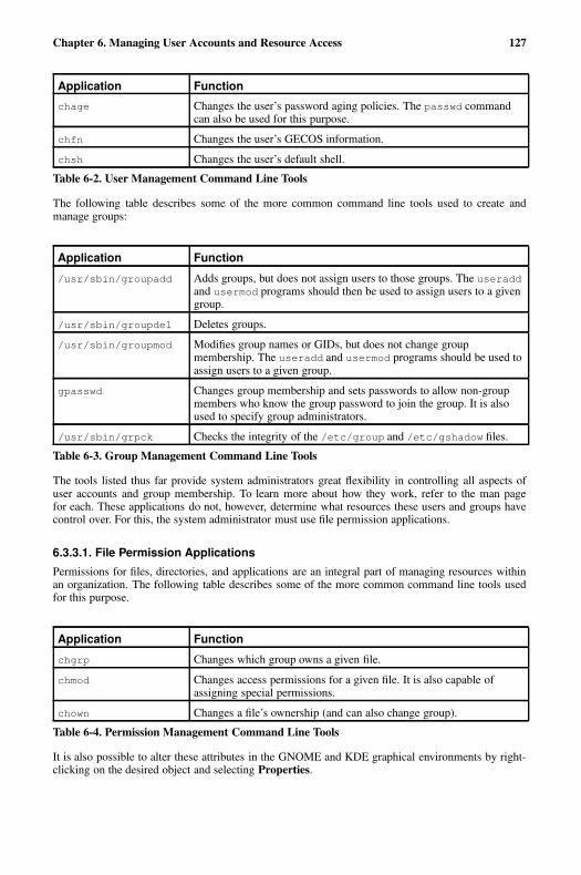
Chapter 6. Managing User Accounts and Resource Access 127
Application Function
chage Changes the user’s password aging policies. The passwd commandcan also be used for this purpose.
chfn Changes the user’s GECOS information.
chsh Changes the user’s default shell.
Table 6-2. User Management Command Line Tools
The following table describes some of the more common command line tools used to create andmanage groups:
Application Function
/usr/sbin/groupadd Adds groups, but does not assign users to those groups. The useraddand usermod programs should then be used to assign users to a givengroup.
/usr/sbin/groupdel Deletes groups.
/usr/sbin/groupmod Modifies group names or GIDs, but does not change groupmembership. The useradd and usermod programs should be used toassign users to a given group.
gpasswd Changes group membership and sets passwords to allow non-groupmembers who know the group password to join the group. It is alsoused to specify group administrators.
/usr/sbin/grpck Checks the integrity of the /etc/group and /etc/gshadow files.
Table 6-3. Group Management Command Line Tools
The tools listed thus far provide system administrators great flexibility in controlling all aspects ofuser accounts and group membership. To learn more about how they work, refer to the man pagefor each. These applications do not, however, determine what resources these users and groups havecontrol over. For this, the system administrator must use file permission applications.
6.3.3.1. File Permission Applications
Permissions for files, directories, and applications are an integral part of managing resources withinan organization. The following table describes some of the more common command line tools usedfor this purpose.
Application Function
chgrp Changes which group owns a given file.
chmod Changes access permissions for a given file. It is also capable ofassigning special permissions.
chown Changes a file’s ownership (and can also change group).
Table 6-4. Permission Management Command Line Tools
It is also possible to alter these attributes in the GNOME and KDE graphical environments by right-clicking on the desired object and selecting Properties.
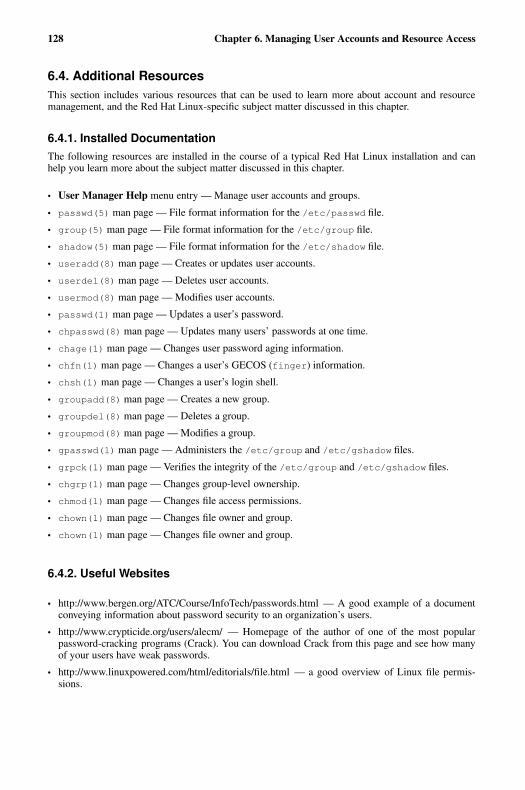
128 Chapter 6. Managing User Accounts and Resource Access
6.4. Additional ResourcesThis section includes various resources that can be used to learn more about account and resourcemanagement, and the Red Hat Linux-specific subject matter discussed in this chapter.
6.4.1. Installed DocumentationThe following resources are installed in the course of a typical Red Hat Linux installation and canhelp you learn more about the subject matter discussed in this chapter.
• User Manager Help menu entry — Manage user accounts and groups.
• passwd(5) man page — File format information for the /etc/passwd file.
• group(5) man page — File format information for the /etc/group file.
• shadow(5) man page — File format information for the /etc/shadow file.
• useradd(8) man page — Creates or updates user accounts.
• userdel(8) man page — Deletes user accounts.
• usermod(8) man page — Modifies user accounts.
• passwd(1) man page — Updates a user’s password.
• chpasswd(8) man page — Updates many users’ passwords at one time.
• chage(1) man page — Changes user password aging information.
• chfn(1) man page — Changes a user’s GECOS (finger) information.
• chsh(1) man page — Changes a user’s login shell.
• groupadd(8) man page — Creates a new group.
• groupdel(8) man page — Deletes a group.
• groupmod(8) man page — Modifies a group.
• gpasswd(1) man page — Administers the /etc/group and /etc/gshadow files.
• grpck(1) man page — Verifies the integrity of the /etc/group and /etc/gshadow files.
• chgrp(1) man page — Changes group-level ownership.
• chmod(1) man page — Changes file access permissions.
• chown(1) man page — Changes file owner and group.
• chown(1) man page — Changes file owner and group.
6.4.2. Useful Websites
• http://www.bergen.org/ATC/Course/InfoTech/passwords.html — A good example of a documentconveying information about password security to an organization’s users.
• http://www.crypticide.org/users/alecm/ — Homepage of the author of one of the most popularpassword-cracking programs (Crack). You can download Crack from this page and see how manyof your users have weak passwords.
• http://www.linuxpowered.com/html/editorials/file.html — a good overview of Linux file permis-sions.

Chapter 6. Managing User Accounts and Resource Access 129
6.4.3. Related BooksThe following books discuss various issues related to account and resource management, and are goodresources for Red Hat Linux system administrators.
• The Red Hat Linux Getting Started Guide; Red Hat, Inc. — Provides an introductory view into fileownership and permissions in the chapter entitled Shell Prompt Basics.
• The Red Hat Linux Reference Guide; Red Hat, Inc. — Contains detailed information on the usersand groups present in Red Hat Linux.
• The Red Hat Linux Customization Guide; Red Hat, Inc. — Includes a chapter on user and groupconfiguration.
• Linux Administration Handbook by Evi Nemeth, Garth Snyder, and Trent R. Hein; Prentice Hall —Provides a chapter on user account maintenance, a section on security as it relates to user accountfiles, and a section on file attributes and permissions.

130 Chapter 6. Managing User Accounts and Resource Access
Chapter 7.
Printers and Printing
Printers are an essential resource for creating a hard copy — a physical depiction of data on paper —version of documents and collateral for business, academic, and home use. Printers have become anindispensable peripheral in all levels of business and institutional computing.
This chapter discusses the various printers available and compare their uses in different computingenvironments. It then describes how printing is supported by Red Hat Linux.
7.1. Types of PrintersLike any other computer peripheral, there are several types of printers available. Some printers employtechnologies that mimic manual typewriter-style functionality, while others spray ink on paper, oruse a laser to generate an image of the page to be printed. Printer hardware interfaces with a PC ornetwork using parallel, serial, or data networking protocols. There are several factors to consider whenevaluating printers for procurement and deployment in your computing environment.
The following sections discuss the various printer types and the protocols that printers use to commu-nicate with computers.
7.1.1. Printing ConsiderationsThere are several aspects to factor into printer evaluations. The following specifies some of the mostcommon criteria when evaluating your printing needs.
7.1.1.1. Function
Evaluating your organizational needs and how a printer services those needs is the essential criteriain determining the right type of printer for your environment. The most important question to ask is"What do we need to print?" Since there are specialized printers for text, images, or any variationthereof, you should be certain that you procure the right tool for your purposes.
For example, if your requirements call for high-quality color images on professional-grade glossypaper, it is recommended to use a dye-sublimation or thermal wax transfer color printer instead of alaser or impact printer.
Conversely, laser or inkjet printers are well-suited for printing rough drafts or documents intended forinternal distribution (such high-volume printers are usually called workgroup printers). Determiningthe needs of the everyday user allows administrators to determine the right printer for the job.
Other factors to consider are features such as duplexing — the ability of the printer to print on bothsides of a piece of paper. Traditionally, printers could only print on one side of the page (called simplexprinting). Most printer models today do not have duplexing by default (or they may be able to simulatea manual duplexing method which forces the user to flip the paper themselves). Some models offeradd-on hardware for duplexing; such add-ons can drive one-time costs up considerably. However,duplex printing may reduce costs over time by reducing the amount of paper used to print documents,thus reducing the cost of consumables — primarily paper.
Another factor to consider is paper size. Most printers are capable of handling the more commonpaper sizes:
• letter — (8 1/2" x 11")
• A4 — (210mm x 297mm)
132 Chapter 7. Printers and Printing
• JIS B5 — (182mm x 257mm)
• legal — (8 1/2" x 14")
If certain departments (such as marketing or design) have specialized needs such as creating postersor banners, there are large-format printers capable of using A3 (297mm x 420mm) or tabloid (11" x17") paper sizes. In addition, there are printers capable of even larger sizes, although these are oftenonly used for specialized purposes, such as printing blueprints.
Additionally, high-end features such as network modules for workgroup and remote site printingshould also be considered during evaluation.
7.1.1.2. Cost
Cost is another factor to consider when evaluating printers. However, determining the one-time costassociated with the purchase of the printer itself is not sufficient. There are other costs to consider,such as consumables, parts and maintenance, and printer add-ons.
Consumables is a general term for printing supplies. Ink and paper are the two most common printingconsumables. Ink is the material that the printer projects onto the medium (the paper).
Ink is itself a generalized term, as not all printers use liquid inks. For example, laser printers use apowder known as toner, while impact printers use ribbons saturated with ink. There are specializedprinters that heat the ink before it is transferred onto paper, while others spray the ink in small dropsonto the printing surface. Ink replacement costs vary widely and depend on whether the containerholding the ink can be recharged (refilled) or if it requires a full replacement of the ink cartridge.
There are also various types of paper or print media to choose from. For most printing needs, a wood-pulp based paper medium is sufficient. However, there are variations of paper that are recommended(or required) for certain printers.
For example, creating an accurate print of a digital image requires a special glossy paper that canwithstand prolonged exposure to natural or artificial lighting, as well as ensure accuracy of colorreproduction; these qualities are known as color fastness. For archival-quality documents that requiredurability and a professional level of legibility (such as contracts, résumés, and permanent records),a matte (or non-glossy) paper should be used. The stock (or thickness) of paper is also important, assome printers have a paper path that is not straight. The use of paper that is too thin or too thick canresult in jams. Some printers can also print on transparencies — a thin film that allows light froma projector to pass through it, displaying the resulting imprinted image on to a projected surface forpresentations and lectures. Specialized papers such as those noted here can affect consumables costs,and should be taken into consideration when evaluating printing needs.
7.2. Impact PrintersImpact printers are the oldest print technologies still in active production. Some of the largest printervendors continue to manufacture, market, and support impact printers, parts, and supplies. Impactprinters are most functional in specialized environments where low-cost printing is essential. Thethree most common forms of impact printers are dot-matrix, daisy-wheel, and line printers.
7.2.1. Dot-Matrix PrintersThe technology behind dot-matrix printing is quite simple. The paper is pressed against a drum(a rubber-coated cylinder) and is intermittently pulled forward as printing progresses. Theelectromagnetically-driven printhead moves across the paper and strikes the printer ribbon situatedbetween the paper and printhead pin. The impact of the printhead against the printer ribbon imprintsink dots on the paper which form human-readable characters.

Chapter 7. Printers and Printing 133
Dot-matrix printers vary in print resolution and overall quality with either 9 or 24-pin printheads.The more pins per inch, the higher the print resolution. Most dot-matrix printers have a maximumresolution around 240 dpi (dots per inch). While this resolution is not as high as those possible inlaser or inkjet printers, there is one distinct advantage to dot-matrix (or any form of impact) printing.Because the printhead must strike the surface of the paper with enough force to transfer ink from aribbon onto the page, it is ideal for environments that must produce carbon copies through the use ofspecial multi-part documents. These documents have carbon (or other pressure-sensitive material) onthe underside and create a mark on the sheet underneath when pressure is applied. Retailers and smallbusinesses often use carbon copies as receipts or bills of sale.
7.2.2. Daisy-wheel PrintersIf you have ever seen or worked with a manual typewriter before, then you understand the techno-logical concept behind daisy-wheel printers. These printers have printheads composed of metallic orplastic wheels cut into petals. Each petal has the form of a letter (in capital and lower-case), number,or punctuation mark on it. When the petal is struck against the printer ribbon, the resulting shapeforces ink onto the paper. Daisy-wheel printers are loud and slow. They cannot print graphics, andcannot change fonts unless the print wheel is physically replaced. With the advent of laser printers,daisy-wheel printers are generally not used in modern computing environments.
7.2.3. Line PrintersAnother type of impact printer somewhat similar to the daisy-wheel is the line printer. However,instead of a print wheel, line printers have a mechanism that allows multiple characters to be simul-taneously printed on the same line. The mechanism may use a large spinning print drum or a loopedprint chain. As the drum or chain are rotated over the paper’s surface, electromechanical hammersbehind the paper push the paper (along with a ribbon) onto the surface of the drum or chain, markingthe paper with the shape of the character on the drum or chain.
Because of the nature of the print mechanism, line printers are much faster than dot-matrix or daisy-wheel printers; however, they tend to be quite loud, have limited multi-font capability, and oftenproduce lower print quality than more recent printing technologies.
Because line printers are used for their speed, they use special tractor-fed paper with pre-punchedholes along each side. This arrangement makes continuous unattended high-speed printing possible,with stops only required when a box of paper runs out.
7.2.4. Impact Printer ConsumablesOf all the printer types, however, impact printers have relatively low consumable costs. Ink ribbonsand paper are the primary recurring costs for impact printers. Some Impact printers (usually line anddot-matrix printers) require tractor-fed paper, which can increase the costs of operation somewhat.
7.3. Inkjet PrintersAn Inkjet printer uses one of the most popular printing technologies today. The relative low cost ofthe printers and multi-purpose printing abilities make it a good choice for small businesses and homeoffices.
Inkjets use quick-drying, water-based inks and a printhead with a series of small nozzles that sprayink on the surface of the paper. The printhead assembly is driven by a belt-fed motor that moves theprinthead across the paper.
134 Chapter 7. Printers and Printing
Inkjets were originally manufactured to print in monochrome (black and white) only. However, theprinthead has since been expanded and the nozzles increased to accommodate cyan, magenta, yellow,and black. This combination of colors (called CMYK) allows for printing images with nearly the samequality as a photo development lab using certain types of coated paper. When coupled with crisp andhighly readable text print quality, inkjet printers are a sound all-in-one choice for monochrome orcolor printing needs.
7.3.1. Inkjet ConsumablesInkjet printers tend to be low cost and scale slightly upward based on print quality, extra features, andthe ability to print on larger formats than the standard legal or letter paper sizes. While the one-timecost of purchasing an inkjet is lower than other printer types, there is the factor of inkjet consumablesthat must be considered. Because demand for inkjets is large and spans the computing spectrum fromhome to enterprise, the procurement of consumables can be costly.
Note
When shopping for an inkjet printer, always make sure you know what kind of ink cartridge(s) itrequires. This is especially critical for color units. CMYK inkjet printers require ink for each color;however, the important point is whether each color is stored in a separate cartridge or not.
Some printers use one multi-chambered cartridge; unless some sort of refilling process is possible,as soon as one color ink runs out, the entire cartridge must be replaced. Other printers use a multi-chambered cartridge for cyan, magenta, and yellow, but also have a separate cartridge for black.In environments where a great deal of text is printed, this type of arrangement can be beneficial.However, the best solution is to find a printer with separate cartridges for each color; you can theneasily replace any color whenever it runs out.
Some inkjet manufacturers also require you to use specially treated paper for printing high-qualityimages and documents. Such paper uses a moderate to high gloss coating formulated to absorb col-ored inks, which prevents clumping (the tendency for water-based inks to collect in certain areaswhere colors blend, causing muddiness or dried ink blots) or banding (where the print output hasa striped pattern of extraneous lines on the printed page.) Consult your printer’s documentation forrecommended papers.
7.4. Laser PrintersAn older technology than inkjet, laser printers are another popular alternative to legacy impact print-ing. Laser printers are known for their high volume output and low cost-per-page. Laser printers areoften deployed in enterprises as a workgroup or departmental print center, where performance, dura-bility, and output requirements are a constant. Because laser printers service these needs so readily(and at a reasonable cost-per-page), the technology is widely regarded as the workhorse of enterpriseprinting.
Laser printers share much of the same technologies as photocopiers. Rollers pull a sheet of paper froma paper tray and through a charge roller, which gives the paper an electrostatic charge. At the sametime, a printing drum is given the opposite charge. The surface of the drum is then scanned by a laser,discharging the drum’s surface and leaving only those points corresponding to the desired text andimage with a charge. This charge is then used to force toner to adhere to the drum’s surface.
The paper and drum are then brought into contact; their differing charges cause the toner to thenadhere to the paper. Finally, the paper travels between fusing rollers, which heat the paper and meltthe toner, fusing it onto the paper’s surface.
Chapter 7. Printers and Printing 135
7.4.1. Color Laser PrintersColor laser printers are an emerging technology created by printer manufacturers whose aim is tocombine the features of laser and inkjet technology into a multi-purpose printer package. The tech-nology is based on traditional monochrome laser printing, but uses additional technologies to createcolor images and documents. Instead of using black toner only, color laser printers use a CMYK tonercombination. The print drum either rotates each color and lays the toner down one color at a time,or lays all four colors down onto a plate and then passes the paper through the drum, transferring thecomplete image onto the paper. Color laser printers also employ fuser oil along with the heated fusingrolls, which further bonds the color toner to the paper and can give varying degrees of gloss to thefinished image.
Because of their increased features, color laser printers are typically twice (or several times) as expen-sive as monochrome laser printers. In calculating the total cost of ownership with respect to printingresources, some administrators may wish to separate monochrome (text) and color (image) function-ality to a dedicated monochrome laser printer and a dedicated inkjet printer, respectively.
7.4.2. Laser ConsumablesDepending on the type of laser printer deployed, consumable costs usually are fixed and scale evenlywith increased usage or print job volume over time. Toner comes in cartridges that are usually replacedoutright; however, some models come with refillable cartridges. Color laser printers require one tonercartridge for each of the four colors. Additionally, color laser printers require fuser oils to bond toneronto paper and waste toner bottles to capture toner spillover. These added supplies raise the consum-ables cost of color laser printers; however, it is worth noting that such consumables, on average, lastabout 6000 pages, which is much greater than comparable inkjet or impact consumable lifespans.Paper type is less of an issue in laser printers, which means bulk purchases of regular xerographic orphotocopy paper are acceptable for most print jobs. However, if you plan to print high-quality images,you should opt for glossy paper for a professional finish.
7.5. Other Printer TypesThere are other types of printers available, mostly special-purpose printers for professional graphicsor publishing organizations. These printers are not for general purpose use, however. Because they arerelegated to niche uses, their prices (both one-time and recurring consumables costs) tend to be higherrelative to more mainstream units.
Thermal Wax Printers
These printers are used mostly for business presentation transparencies and for color proofing(creating test documents and images for close quality inspection before sending off master docu-ments to be pressed on industrial four-color offset printers). Thermal wax printers use sheet-sized,belt driven CMYK ribbons and specially-coated paper or transparencies. The printhead containsheating contacts that melt each colored wax onto the paper as it is rolled through the printer.
Dye-Sublimation Printers
Used in organizations such as service bureaus — where professional quality documents, pam-phlets, and presentations are more important than consumables costs — dye-sublimation (ordye-sub) printers are the workhorses of quality CMYK printing. The concepts behind dye-subprinters are similar to thermal wax printers except for the use of diffusive plastic dye film insteadof colored wax as the ink element. The printhead heats the colored film and vaporizes the imageonto specially coated paper.
136 Chapter 7. Printers and Printing
Dye-sub is quite popular in the design and publishing world as well as the scientific researchfield, where preciseness and detail are required. Such detail and print quality comes at a price, asdye-sub printers are also known for their high costs-per-page.
Solid Ink Printers
Used mostly in the packaging and industrial design industries, solid ink printers are prized fortheir ability to print on a wide variety of paper types. Solid ink printers, as the name implies, usehardened ink sticks that that are melted and sprayed through small nozzles on the printhead. Thepaper is then sent through a fuser roller which further forces the ink onto the paper.
The solid ink printer is ideal for prototyping and proofing new designs for product packages; assuch, most service-oriented businesses would not have a need for this type of printer.
7.6. Printer Languages and TechnologiesBefore the advent of laser and inkjet technology, impact printers could only print standard, justifiedtext with no variation in letter size or font style. Today, printers are able to process complex documentswith embedded images, charts, and tables in multiple frames and in several languages, all in one printjob. Such complexity must adhere to some format conventions. This is what spurred the developmentof the page description language (or PDL) — a specialized document formatting language speciallymade for computer communication with printers.
Over the years, printer manufacturers have developed their own proprietary languages to describedocument formats. However, such proprietary languages are applied only to the printers that the man-ufacturers created themselves. If, for example, you were to send a print-ready file using a proprietaryPDL to a professional press, there was no guarantee that your file would be compatible with theprinter’s machines. The issue of portability came into question.
Xerox® developed the Interpress™ protocol for their line of printers, but full adoption of the languageby the rest of the printing industry was never realized. Two original developers of Interpress left Xeroxand formed Adobe®, a software company catering mostly to electronic graphics and document profes-sionals. At Adobe, they developed a widely-adopted PDL called PostScript™, which uses a markuplanguage to describe text formatting and image information that could be processed by printers. Atthe same time, the Hewlett-Packard® Company developed the Printer Control Language™ (or PCL)for use in their ubiquitous Laser and inkjet printer lines. PostScript and PCL are widely adopted PDLsand are supported by most printer manufacturers (along with the printer’s own proprietary languages,when available).
PDLs work on the same principle as computer programming languages. When a document is readyfor printing, the PC or workstation takes the images, typographical information, and document layout,and uses them as objects that form instructions for the printer to process. The printer then translatesthose objects into rasters, a series of scanned lines that form an image of the document (called RasterImage Processing or RIP), and prints the output onto the page as one image, complete with text andany graphics included. This work-flow makes printing documents of any complexity uniform andstandard, allowing for little or no variation in printing from one printer to the next. PDLs are designedto be portable to any format, and scalable to fit several paper sizes.
Choosing the right printer is a matter of determining what standards the various departments in yourorganization have adopted for their needs. Most departments use word processing and other produc-tivity software that use the PostScript language for outputting to printers. However, if your graphicsdepartment requires PCL or some proprietary form of printing, you must take that into considerationas well.
Chapter 7. Printers and Printing 137
7.7. Networked Versus Local PrintersDepending on organizational needs, it may be unnecessary to assign one printer to each member ofyour organization. Such overlap in expenditure can eat into allotted budgets, leaving less capital forother necessities. While local printers attached via a parallel or USB cable to every workstation are anideal solution for the user, it is usually not economically feasible.
Printer manufacturers have addressed this need by developing departmental (or workgroup) printers.These machines are usually durable, fast, and have long-life consumables. Workgroup printers usuallyare attached to a print server, a standalone device (such as a reconfigured workstation) that handlesprint jobs and routes output to the proper printer when available. More recent departmental printersinclude built-in or add-on network interfaces that eliminate the need for a dedicated print server.
7.8. Red Hat Linux-Specific InformationThe following describes the various features specific to Red Hat Linux that relate to printers andprinting.
The Printer Configuration Tool allows users to configure a printer in Red Hat Linux. This tool helpsmaintain the printer configuration file, print spool directories, and print filters.
Starting with version 9, Red Hat Linux defaults to the CUPS printing system. The previous defaultprinting system, LPRng is still provided. If the system was upgraded from a previous Red Hat Linuxversion that used LPRng, the upgrade process did not replace LPRng with CUPS; the system willcontinue to use LPRng.
If a system was upgraded from a previous Red Hat Linux version that used CUPS, the upgrade processpreserved the configured queues, and the system will continue to use CUPS.
The Printer Configuration Tool configures both the CUPS and LPRng printing system, depending onwhich one the system is configured to use. When you apply changes, it configures the active printingsystem.
To use the Printer Configuration Tool you must have root privileges. To start the application, selectMain Menu Button (on the Panel) => System Settings => Printing, or type the command redhat-config-printer. This command automatically determines whether to run the graphical or text-based version depending on whether the command is executed in the graphical X Window Systemenvironment or from a text-based console.
You can also force the Printer Configuration Tool to run as a text-based application by using thecommand redhat-config-printer-tui from a shell prompt.
Important
Do not edit the /etc/printcap file or the files in the /etc/cups/ directory. Each time the printerdaemon (lpd or cups) is started or restarted, new configuration files are dynamically created. Thefiles are dynamically created when changes are applied with Printer Configuration Tool as well.
If you are using LPRng and want to add a printer without using the Printer Configuration Tool,edit the /etc/printcap.local file. The entries in /etc/printcap.local are not displayed inthe Printer Configuration Tool but are read by the printer daemon. If you upgraded your systemfrom a previous version of Red Hat Linux, your existing configuration file was converted to the newformat used by this application. Each time a new configuration file is generated, the old file is savedas /etc/printcap.old.
If you are using CUPS, the Printer Configuration Tool does not display any queues or shares notconfigured using the Printer Configuration Tool; however, it will not remove them from the config-uration files.
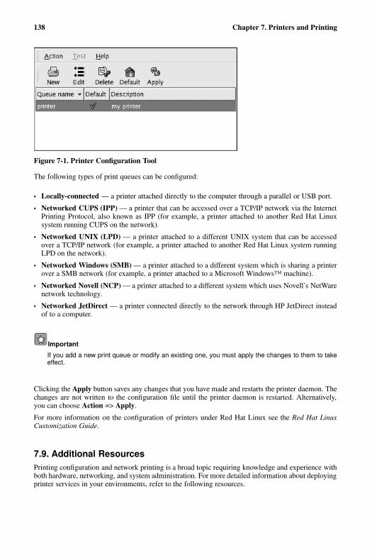
138 Chapter 7. Printers and Printing
Figure 7-1. Printer Configuration Tool
The following types of print queues can be configured:
• Locally-connected — a printer attached directly to the computer through a parallel or USB port.
• Networked CUPS (IPP) — a printer that can be accessed over a TCP/IP network via the InternetPrinting Protocol, also known as IPP (for example, a printer attached to another Red Hat Linuxsystem running CUPS on the network).
• Networked UNIX (LPD) — a printer attached to a different UNIX system that can be accessedover a TCP/IP network (for example, a printer attached to another Red Hat Linux system runningLPD on the network).
• Networked Windows (SMB) — a printer attached to a different system which is sharing a printerover a SMB network (for example, a printer attached to a Microsoft Windows™ machine).
• Networked Novell (NCP) — a printer attached to a different system which uses Novell’s NetWarenetwork technology.
• Networked JetDirect — a printer connected directly to the network through HP JetDirect insteadof to a computer.
Important
If you add a new print queue or modify an existing one, you must apply the changes to them to takeeffect.
Clicking the Apply button saves any changes that you have made and restarts the printer daemon. Thechanges are not written to the configuration file until the printer daemon is restarted. Alternatively,you can choose Action => Apply.
For more information on the configuration of printers under Red Hat Linux see the Red Hat LinuxCustomization Guide.
7.9. Additional ResourcesPrinting configuration and network printing is a broad topic requiring knowledge and experience withboth hardware, networking, and system administration. For more detailed information about deployingprinter services in your environments, refer to the following resources.
Chapter 7. Printers and Printing 139
7.9.1. Installed Documentation
• printcap(5) man page — File format for the /etc/printcap printer configuration file.
• lpr(1) man page — Information on printing selected files on the printer of your choice.
• lpd(8) man page — The LPRng printer daemon.
• lprm(1) man page — Information on removing print jobs from a printer queue.
• cupsd(8) man page — The CUPS printer daemon.
• cupsd.conf(5) man page — The file format for the CUPS printer daemon configuration file.
• classes.conf(5) man page — The file format for the CUPS class configuration file.
• Files in /usr/share/doc/cups- � version � — The document collection for CUPS.
• Files in /usr/share/doc/LPRng- � version � — The document collection for LPRng.
7.9.2. Useful Websites
• http://www.webopedia.com/TERM/p/printer.html — General definitions of printers and descrip-tions of printer types.
• http://www.linuxprinting.org/ — A database of documents about printing, along with a database ofnearly 1000 printers compatible with Linux printing facilities.
• http://www.cups.org/ — Documentation, FAQs, and newsgroups about CUPS.
• http://www.tldp.org/HOWTO/Printing-HOWTO/index.html — The Linux Printing-HOWTO fromthe Linux Documentation Project.
7.9.3. Related Books
• Network Printing by Matthew Gast and Todd Radermacher; O’Reilly & Associates, Inc. — Com-prehensive information on using Linux as a print server in heterogeneous environments.
• The Red Hat Linux Customization Guide; Red Hat, Inc. — Includes a chapter on printer configura-tion.

140 Chapter 7. Printers and Printing
Chapter 8.
Planning for Disaster
Disaster planning is a subject that is easy for a system administrator to forget — it is not pleasant, andit always seems that there is something else more pressing to do. However, letting disaster planningslide is one of the worst things a system administrator can do.
Although it is often the dramatic disasters (such as a fire, flood, or storm) that first come to mind, themore mundane problems (such as construction workers cutting cables or even an overflowing sink)can be just as disruptive. Therefore, the definition of a disaster that a system administrator should keepin mind is any unplanned event that disrupts the normal operation of the organization.
While it would be impossible to list all the different types of disasters that could strike, this sectionexamines the leading factors that are part of each type of disaster so that any possible exposure can beexamined not in terms of its likelihood, but in terms of the factors that could lead to disaster.
8.1. Types of DisastersIn general, there are four different factors that can trigger a disaster. These factors are:
• Hardware failures
• Software failures
• Environmental failures
• Human errors
8.1.1. Hardware FailuresHardware failures are easy to understand — the hardware fails, and work grinds to a halt. What is moredifficult to understand is the nature of the failures and how your exposure to them can be minimized.Here are some approaches that you can use:
8.1.1.1. Keeping Spare Hardware
At its simplest, exposure due to hardware failures can be reduced by having spare hardware available.Of course, this approach assumes two things:
• Someone on-site has the necessary skills to diagnose the problem, identify the failing hardware,and replace it.
• A replacement for the failing hardware is available.
These issues are covered in more detail below.
8.1.1.1.1. Having the Skills
Depending on your past experience and the hardware involved, having the necessary skills might bea non-issue. However, if you have not worked with hardware before, you might consider looking intolocal community colleges for introductory courses on PC repair. While such a course is not in and ofitself sufficient to prepare you for tackling problems with an enterprise-level server, it is a good wayto learn the basics (proper handling of tools and components, basic diagnostic procedures, and so on).
142 Chapter 8. Planning for Disaster
Tip
Before taking the approach of first fixing it yourself, make sure that the hardware in question:
• Is not still under warranty
• Is not under a service/maintenance contract of any kind
If you attempt repairs on hardware that is covered by a warranty and/or service contract, you arelikely violating the terms of these agreements and jeopardizing your continued coverage.
However, even with minimal skills, it might be possible to effectively diagnose and replace failinghardware — if you choose your stock of replacement hardware properly.
8.1.1.1.2. What to Stock?
This question illustrates the multi-faceted nature of anything related to disaster recovery. When con-sidering what hardware to stock, here are some of the issues you should keep in mind:
• Maximum allowable downtime
• The skill required to make the repair
• Budget available for spares
• Storage space required for spares
• Other hardware that could utilize the same spares
Each of these issues has a bearing on the types of spares that should be stocked. For example, stockingcomplete systems would tend to minimize downtime and require minimal skills to install but would bemuch more expensive than having a spare CPU and RAM module on a shelf. However, this expensemight be worthwhile if your organization has several dozen identical servers that could benefit from asingle spare system.
No matter what the final decision, the following question is inevitable and is discussed next.
8.1.1.1.2.1. How Much to Stock?
The question of spare stock levels is also multi-faceted. Here the main issues are:
• Maximum allowable downtime
• Projected rate of failure
• Estimated time to replenish stock
• Budget available for spares
• Storage space required for spares
• Other hardware that could utilize the same spares
At one extreme, for a system that can afford to be down a maximum of two days, and a spare thatmight be used once a year and could be replenished in a day, it would make sense to carry only onespare (and maybe even none, if you were confident of your ability to secure a spare within 24 hours).
At the other end of the spectrum, a system that can afford to be down no more than a few minutes,and a spare that might be used once a month (and could take several weeks to replenish) might meanthat a half dozen spares (or more) should be on the shelf.
Chapter 8. Planning for Disaster 143
8.1.1.1.3. Spares That Are Not Spares
When is a spare not a spare? When it is hardware that is in day-to-day use but is also available to serveas a spare for a higher-priority system should the need arise. This approach has some benefits:
• Less money dedicated to "non-productive" spares
• The hardware is known to be operative
There are, however, downsides to this approach:
• Normal production of the lower-priority task is interrupted
• There is an exposure should the lower-priority hardware fail (leaving no spare for the higher-priorityhardware)
Given these constraints, the use of another production system as a spare may work, but the success ofthis approach hinges on the system’s specific workload and the impact the system’s absence has onoverall data center operations.
8.1.1.2. Service Contracts
Service contracts make the issue of hardware failures someone else’s problem. All that is necessaryfor you to do is to confirm that a failure has, in fact, occurred and that it does not appear to have asoftware-related cause. You then make a telephone call, and someone shows up to make things rightagain.
It seems so simple. But as with most things in life, there is more to it than meets the eye. Here aresome things that you must consider when looking at a service contract:
• Hours of coverage
• Response time
• Parts availability
• Available budget
• Hardware to be covered
We explore each of these details more closely below.
8.1.1.2.1. Hours of Coverage
Different service contracts are available to meet different needs; one of the big variables betweendifferent contracts relates to the hours of coverage. Unless you are willing to pay a premium for theprivilege, you cannot just call any time and expect to see a technician at your door a short time later.
Instead, depending on your contract, you might find that you cannot even phone the service companyuntil a specific day/time, or if you can, they will not dispatch a technician until the day/time specifiedfor your contract.
Most hours of coverage are defined in terms of the hours and the days during which a technician maybe dispatched. Some of the more common hours of coverage are:
• Monday through Friday, 09:00 to 17:00
• Monday through Friday, 12/18/24 hours each day (with the start and stop times mutually agreedupon)
• Monday through Saturday (or Monday through Sunday), same times as above
144 Chapter 8. Planning for Disaster
As you might expect, the cost of a contract increases with the hours of coverage. In general, extendingthe coverage Monday through Friday tends to cost less than adding on Saturday and Sunday coverage.
But even here there is a possibility of reducing costs if you are willing to do some of the work.
8.1.1.2.1.1. Depot Service
If your situation does not require anything more than the availability of a technician during standardbusiness hours and you have sufficient experience to be able to determine what is broken, you mightconsider looking at depot service. Known by many names (including walk-in service and drop-offservice), manufacturers may have service depots where technicians work on hardware brought in bycustomers.
Depot service has the benefit of being as fast as you are. You do not have to wait for a technician tobecome available and show up at your facility. Depot technicians do not go out on customer calls,meaning that there will be someone to work on your hardware as soon as you can get it to the depot.
Because depot service is done at a central location, there is a good chance that any required parts willbe available. This can eliminate the need for an overnight shipment or waiting for a part to be drivenseveral hundred miles from another office that just happened to have that part in stock.
There are some trade-offs, however. The most obvious is that you cannot choose the hours of service— you get service when the depot is open. Another aspect to this is that the technicians do not workpast their quitting time, so if your system failed at 16:30 on a Friday and you got the system to thedepot by 17:00, it will not be worked on until the technicians arrive at work the following Mondaymorning.
Another trade-off is that depot service depends on having a depot nearby. If your organization islocated in a metropolitan area, this is likely not going to be a problem. However, organizations inmore rural locations may find that a depot is a long drive away.
Tip
If considering depot service, take a moment and consider the mechanics of actually getting thehardware to the depot. Will you be using a company vehicle or your own? If your own, does yourvehicle have the necessary space and load capacity? What about insurance? Will more than oneperson be necessary to load and unload the hardware?
Although these are rather mundane concerns, they should be addressed before making the decisionto use depot service.
8.1.1.2.2. Response Time
In addition to the hours of coverage, many service agreements specify a level of response time. Inother words, when you call requesting service, how long will it be before a technician arrives? As youmight imagine, a faster response time equates to a more expensive service agreement.
There are limits to the response times that are available. For instance, the travel time from the manu-facturer’s office to your facility has a large bearing on the response times that are possible1. Responsetimes in the four hour range are usually considered among the quicker offerings. Slower response
1. And this would likely be considered a best-case response time, as technicians usually are responsible for
territories that extend away from their office in all directions. If you are at one end of their territory and the only
available technician is at the other end, the response time will be even longer.
Chapter 8. Planning for Disaster 145
times can range from eight hours (which effectively becomes "next day" service for a standard busi-ness hours agreement), to 24 hours. As with every other aspect of a service agreement, even thesetimes are negotiable — for the right price.
Note
Although it is not a common occurrence, you should be aware that service agreements with re-sponse time clauses can sometimes stretch a manufacturer’s service organization beyond its abilityto respond. It is not unheard of for a very busy service organization to send somebody — anybody— on a short response-time service call just to meet their response time commitment. This personapparently diagnoses the problem, calling "the office" to have someone bring "the right part."
In fact, they are just waiting until someone who is actually capable of handling the call arrives.
While it might be understandable to see this happen under extraordinary circumstances (such aspower problems that have damaged systems throughout their service area), if this is a consistentmethod of operation you should contact the service manager and demand an explanation.
If your response time needs are stringent (and your budget correspondingly large), there is one ap-proach that can cut your response times even further — to zero.
8.1.1.2.2.1. Zero Response Time — Having an On-Site Technician
Given the appropriate situation (you are one of the biggest customers in the area), sufficient need(downtime of any magnitude is unacceptable), and financial resources (if you have to ask for theprice, you probably cannot afford it), you might be a candidate for a full-time, on-site technician. Thebenefits of having a technician always standing by are obvious:
• Instant response to any problem
• A more proactive approach to system maintenance
As you might expect, this option can be very expensive, particularly if you require an on-site technician24x7. But if this approach is appropriate for your organization, you should keep a number of points inmind in order to gain the most benefit.
First, on-site technicians need many of the resources of a regular employee, such as a workspace,telephone, appropriate access cards and/or keys, and so on.
On-site technicians are not very helpful if they do not have the proper parts. Therefore, make surethat secure storage is set aside for the technician’s spare parts. In addition, make sure that the tech-nician keeps a stock of parts appropriate for your configuration and that those parts are not routinely"cannibalized" by other technicians for their customers.
8.1.1.2.3. Parts Availability
Obviously, the availability of parts plays a large role in limiting your organization’s exposure to hard-ware failures. In the context of a service agreement, the availability of parts takes on another dimen-sion, as the availability of parts applies not only to your organization, but to any other customer inthe manufacturer’s territory that might need those parts as well. Another organization that has pur-chased more of the manufacturer’s hardware than you might get preferential treatment when it comesto getting parts (and technicians, for that matter).
Unfortunately, there is little that can be done in such circumstances, short of working out the problemwith the service manager.
146 Chapter 8. Planning for Disaster
8.1.1.2.4. Available Budget
As outlined above, service contracts vary in price according to the nature of the services being pro-vided. Keep in mind that the costs associated with a service contract are a recurring expense; eachtime the contract is due to expire you must negotiate a new contract and pay again.
8.1.1.2.5. Hardware to be Covered
Here is an area where you might be able to help keep costs to a minimum. Consider for a moment thatyou have negotiated a service agreement that has an on-site technician 24x7, on-site spares — youname it. Every single piece of hardware you have purchased from this vendor is covered, includingthe PC that the company receptionist uses to surf the Web while answering phones and handing outvisitor badges.
Does that PC really need to have someone on-site 24x7? Even if the PC were vital to the receptionist’sjob, the receptionist only works from 09:00 to 17:00; it is highly unlikely that:
• The PC will be in use from 17:00 to 09:00 the next morning (not to mention weekends)
• A failure of this PC will be noticed, except between 09:00 and 17:00
Therefore, paying on the chance that this PC might need to be serviced in the middle of a Saturdaynight is a waste of money.
The thing to do is to split up the service agreement such that non-critical hardware is grouped sepa-rately from more critical hardware. In this way, costs can be kept as low as possible.
Note
If you have twenty identically-configured servers that are critical to your organization, you might betempted to have a high-level service agreement written for only one or two, with the rest covered by amuch less expensive agreement. Then, the reasoning goes, no matter which one of the servers failson a weekend, you will say that it is the one eligible for high-level service.
Do not do this. Not only is it dishonest, most manufacturers keep track of such things by using serialnumbers. Even if you figure out a way around such checks, you will spend far more after beingdiscovered than you will by being honest and paying for the service you really need.
8.1.2. Software FailuresSoftware failures can result in extended downtimes. For example, owners of a certain brand of com-puter systems noted for their high-availability features recently experienced this firsthand. A bug inthe time handling code of the computer’s operating system resulted in each customer’s systems crash-ing at a certain time of a certain day. While this particular situation is a more spectacular example of asoftware failure in action, other software-related failures may be less dramatic, but still as devastating.
Software failures can strike in one of two areas:
• Operating system
• Applications
Each type of failure has its own specific impact and is explored in more detail in the following sections.
Chapter 8. Planning for Disaster 147
8.1.2.1. Operating System Failures
In this type of failure, the operating system is responsible for the disruption in service. Operatingsystem failures come from two areas:
• Crashes
• Hangs
The main thing to keep in mind about operating system failures is that they take out everything that thecomputer was running at the time of the failure. As such, operating system failures can be devastatingto production.
8.1.2.1.1. Crashes
Crashes occur when the operating system experiences an error condition from which it cannot recover.The reasons for crashes can range from an inability to handle an underlying hardware problem to abug in the kernel-level code comprising the operating system. When an operating system crashes, thesystem must be rebooted in order to continue production.
8.1.2.1.2. Hangs
When the operating system stops handling system events, the system grinds to a halt. This is knownas a hang. Hangs can be caused by deadlocks (two resource consumers contending for resources theother has) and livelocks (two or more processes responding to each other’s activities, but doing nouseful work), but the end result is the same — a complete lack of productivity.
8.1.2.2. Application Failures
Unlike operating system failures, application failures can be more limited in the scope of their damage.Depending on the specific application, a single application failing might impact only one person. Onthe other hand, if it is a server application servicing a large population of client applications, theconsequences of a failure would be much more widespread.
Application failures, like operating system failures, can be due to hangs and crashes; the only differ-ence is that here it is the application that is hanging or crashing.
8.1.2.3. Getting Help — Software Support
Just as hardware vendors provide support for their products, many software vendors make supportpackages available to their customers. Except for the obvious differences (no spare hardware is re-quired, and most of the work can be done by support personnel over the phone), software supportcontracts can be quite similar to hardware support contracts.
The level of support provided by a software vendor can vary. Here are some of the more commonsupport strategies employed today:
• Documentation
• Self support
• Web or email support
• Telephone support
• On-site support
Each type of support is described in more detail below.
148 Chapter 8. Planning for Disaster
8.1.2.3.1. Documentation
Although often overlooked, software documentation can serve as a first-level support tool. Whetheronline or printed, documentation often contains the information necessary to resolve many issues.
8.1.2.3.2. Self Support
Self support relies on the customer using online resources to resolve their own software-related is-sues. Quite often these resources take the form of Web-based FAQs (Frequently Asked Questions) orknowledge bases.
FAQs often have little or no selection capabilities, leaving the customer to scroll through questionafter question in the hopes of finding one that addresses the issue at hand. Knowledge bases tend to besomewhat more sophisticated, allowing the entry of search terms. Knowledge bases can also be quiteextensive in scope, making it a good tool for resolving problems.
8.1.2.3.3. Web or Email Support
Many times what looks like a self support website also includes Web-based forms or email addressesthat make it possible to send questions to support staff. While this might at first glance appear to be animprovement over a good self support website, it really depends on the people answering the email.
If the support staff is overworked, it is difficult to get the necessary information from them, as theirmain concern is to quickly respond to each email and move on to the next one. The reason for this isbecause nearly all support personnel are evaluated by the number of issues that they resolve. Escalationof issues is also difficult because there is little that can be done within an email to encourage moretimely and helpful responses — particularly when the person reading your email is in a hurry to moveon to the next one.
The way to get the best service is to make sure that your email addresses all the questions that asupport technician might ask, such as:
• Clearly describe the nature of the problem
• Include all pertinent version numbers
• Describe what you have already done in an attempt to address the problem (applied the latestpatches, rebooted with a minimal configuration, etc.)
By giving the support technician more information, you stand a better chance of getting the supportyou need.
8.1.2.3.4. Telephone Support
As the name implies, telephone support entails speaking to a support technician via telephone. Thisstyle of support is most similar to hardware support; that there can be various levels of support avail-able (with different hours of coverage, response time, etc.).
8.1.2.3.5. On-Site Support
Also known as on-site consulting, this is the most expensive approach to software support. Normally itis reserved for resolving specific issues or making critical changes, such as initial software installationand configuration, major upgrades, and so on. As expected, this is the most expensive type of softwaresupport available.
Still, there are instances where on-site support makes sense. As an example, consider a small organi-zation with a single system administrator. The organization is going to be deploying its first database
Chapter 8. Planning for Disaster 149
server, but the deployment (and the organization) is not large enough to justify hiring a dedicateddatabase administrator. In this situation, it can often be cheaper to bring in a specialist from thedatabase vendor to handle the initial deployment (and occasionally later on, as the need arises) then itwould be to train the system administrator in a skill that will be seldom used.
8.1.3. Environmental FailuresEven though the hardware may be running perfectly, and even though the software may be configuredproperly and is working as it should, problems can still occur. The most common problems that occuroutside of the system itself have to do with the physical environment in which the system resides.
Environmental issues can be broken into four major categories:
• Building integrity
• Electricity
• Air conditioning
• Weather and the outside world
8.1.3.1. Building Integrity
For such a seemingly simple structure, a building performs a great many functions. It provides shelterfrom the elements. It provides the proper micro-climate for the building’s contents. It has mechanismsto provide power and to protect against fire, theft, and vandalism. Performing all these functions, it isnot surprising that there is a great deal that can go wrong with a building. Here are some possibilitiesto consider:
• Roofs can leak, allowing water into data centers.
• Various building systems (such as water, sewer, or air handling) can fail, rendering the buildinguninhabitable.
• Floors may have insufficient load-bearing capacity to hold the equipment you want to put in thedata center.
It is important to have a creative mind when it comes to thinking about the different ways buildingscan fail. The list above is only meant to start you thinking along the proper lines.
8.1.3.2. Electricity
Because electricity is the lifeblood of any computer system, power-related issues are paramount inthe mind of system administrators everywhere. There are several different aspects to power; they arecovered in more detail in the following sections.
8.1.3.2.1. The Security of Your Power
First, it is necessary to determine how secure your normal power supply may be. Just like nearly everyother data center, you probably obtain your power from a local power company via power transmissionlines. Because of this, there are limits to what you can do to make sure that your primary power supplyis as secure as possible.
150 Chapter 8. Planning for Disaster
Tip
Organizations located near the boundaries of a power company might be able to negotiate connec-tions to two different power grids:
• The one servicing your area
• The one from the neighboring power company
The costs involved in running power lines from the neighboring grid are sizable, making this an optiononly for larger organizations. However, such organizations find that the redundancy gained outweighthe costs in many cases.
The main things to check are the methods by which the power is brought onto your organization’sproperty and into the building. Are the transmission lines above ground or below? Above-groundlines are susceptible to:
• Damage from extreme weather conditions (ice, wind, lightning)
• Traffic accidents that damage the poles and/or transformers
• Animals straying into the wrong place and shorting out the lines
However, below-ground lines have their own unique shortcomings:
• Damage from construction workers digging in the wrong place
• Flooding
• Lightning (though much less so than above-ground lines)
Continue to trace the power lines into your building. Do they first go to an outside transformer? Isthat transformer protected from vehicles backing into it or trees falling on it? Are all exposed shutoffswitches protected against unauthorized use?
Once inside your building, could the power lines (or the panels to which they attach) be subject toother problems? For instance, could a plumbing problem flood the electrical room?
Continue tracing the power into the data center; is there anything else that could unexpectedly interruptyour power supply? For example, is the data center sharing one or more circuits with non-data centerloads? If so, the external load might one day trip the circuit’s overload protection, taking down thedata center as well.
8.1.3.2.2. Power Quality
It is not enough to ensure that the data center’s power source is as secure as possible. You must alsobe concerned with the quality of the power being distributed throughout the data center. There areseveral factors that must be considered:
Voltage
The voltage of the incoming power must be stable, with no voltage reductions (often called sags,droops, or brownouts) or voltage increases (often known as spikes and surges).
Waveform
The waveform must be a clean sine wave, with minimal THD (Total Harmonic Distortion).
Frequency
The frequency must be stable (most countries use a power frequency of either 50Hz or 60Hz).

Chapter 8. Planning for Disaster 151
Noise
The power must not include any RFI (Radio Frequency Interference) or EMI (Electro-MagneticInterference) noise.
Current
The power must be supplied at a current rating sufficient to run the data center.
Power supplied directly from the power company does not normally meet the standards necessaryfor a data center. Therefore, some level of power conditioning is usually required. There are severaldifferent approaches possible:
Surge Protectors
Surge protectors do just what their name implies — they filter surges from the power supply. Mostdo nothing else, leaving equipment vulnerable to damage from other power-related problems.
Power Conditioners
Power conditioners attempt a more comprehensive approach; depending on the sophistication ofthe unit, power conditioners often can take care of most of the types of problems outlined above.
Motor-Generator Sets
A motor-generator set is essentially a large electric motor powered by your normal power supply.The motor is attached to a large flywheel, which is, in turn, attached to a generator. The motorturns the flywheel and generator, which generates electricity in sufficient quantities to run the datacenter. In this way, the data center power is electrically isolated from outside power, meaning thatmost power-related problems are eliminated. The flywheel also provides the ability to maintainpower through short outages, as it takes several seconds for the flywheel to slow to the point atwhich it can no longer generate power.
Uninterruptible Power Supplies
Some types of Uninterruptible Power Supplies (more commonly known as UPSs) include most(if not all) of the protection features of a power conditioner2.
With the last two technologies listed above, we have started in on the topic most people think of whenthey think about power — backup power. In the next section, different approaches to providing backuppower are explored.
8.1.3.2.3. Backup Power
One power-related term that nearly everyone has heard is the term blackout. A blackout is a completeloss of electrical power and may last from a fraction of a second to weeks.
Because the length of blackouts can vary so greatly, it is necessary to approach the task of providingbackup power using different technologies for power outages of different lengths.
Tip
The most frequent blackouts last, on average, no more than a few seconds; longer outages are muchless frequent. Therefore, concentrate first on protecting against blackouts of only a few minutes induration, then work out methods of reducing your exposure to longer outages.
2. UPSs are discussed in more detail in Section 8.1.3.2.3.2 Providing Power For the Next Few Minutes.
152 Chapter 8. Planning for Disaster
8.1.3.2.3.1. Providing Power For the Next Few Seconds
Since the majority of outages last only a few seconds, your backup power solution must have twoprimary characteristics:
• Very short time to switch to backup power (known as transfer time)
• A runtime (the time that backup power will last) measured in seconds to minutes
The backup power solutions that match these characteristics are motor-generator sets and UPSs. Theflywheel in the motor-generator set allows the generator to continue producing electricity for enoughtime to ride out outages of a second or so. Motor-generator sets tend to be quite large and expensive,making them a practical solution only for mid-sized and larger data centers.
However, another technology — called a UPS — can fill in for those situations where a motor-generator set is too expensive. It can also handle longer outages.
8.1.3.2.3.2. Providing Power For the Next Few Minutes
UPSs can be purchased in a variety of sizes — small enough to run a single low-end PC for fiveminutes or large enough to power an entire data center for an hour or more.
UPSs are made up of the following parts:
• A transfer switch for switching from the primary power supply to the backup power supply
• A battery, for providing backup power
• An inverter, which converts the DC current from the battery into the AC current required by thedata center hardware
Apart from the size and battery capacity of the unit, UPSs come in two basic types:
• The offline UPS uses its inverter to generate power only when the primary power supply fails.
• The online UPS uses its inverter to generate power all the time, powering the inverter via its batteryonly when the primary power supply fails.
Each type has their advantages and disadvantages. The offline UPS is usually less expensive, becausethe inverter does not have to be constructed for full-time operation. However, a problem in the inverterof an offline UPS will go unnoticed (until the next power outage, that is).
Online UPSs tend to be better at providing clean power to your data center; after all, an online UPS isessentially generating power for you full time.
But no matter what type of UPS you choose, you must properly size the UPS to your anticipated load(thereby ensuring that the UPS has sufficient capacity to produce electricity at the required voltageand current), and you must determine how long you would like to be able to run your data center onbattery power.
To determine this information, you must first identify those loads that are to be serviced by the UPS.Go to each piece of equipment and determine how much power it draws (this is normally listed on alabel near the unit’s power cord). Write down the voltage, watts, and/or amps. Once you have thesefigures for all of the hardware, you must convert them to VA (Volt-Amps). If you have a wattagenumber, you can use the listed wattage as the VA; if you have amps, multiply it by volts to get VA. Byadding the VA figures you can arrive at the approximate VA rating required for the UPS.
Chapter 8. Planning for Disaster 153
Note
Strictly speaking, this approach to calculating VA is not entirely correct; however, to get the true VAyou would need to know the power factor for each unit, and this information is rarely, if ever, provided.In any case, the VA numbers obtained from this approach reflects worst-case values, leaving a largemargin of error for safety.
Determining runtime is more of a business question than a technical question — what sorts of outagesare you willing to protect against, and how much money are you prepared to spend to do so? Mostsites select runtimes that are less than an hour or two at most, as battery-backed power becomes veryexpensive beyond this point.
8.1.3.2.3.3. Providing Power For the Next Few Hours (and Beyond)
Once we get into power outages that are measured in days, the choices get even more expensive. Thetechnologies capable of handling long-term power outages are limited to generators powered by sometype of engine — diesel and gas turbine, primarily.
Note
Keep in mind that engine-powered generators require regular refueling while they are running. Youshould know your generator’s fuel "burn" rate at maximum load and arrange fuel deliveries accord-ingly.
At this point, your options are wide open, assuming your organization has sufficient funds. This is alsoan area where experts should help you determine the best solution for your organization. Very few sys-tem administrators have the specialized knowledge necessary to plan the acquisition and deploymentof these kinds of power generation systems.
Tip
Portable generators of all sizes can be rented, making it possible to have the benefits of generatorpower without the initial outlay of money necessary to purchase one. However, keep in mind thatin disasters affecting your general vicinity, rented generators will be in very short supply and veryexpensive.
8.1.3.2.4. Planning for Extended Outages
While a black out of five minutes is little more than an inconvenience to the personnel in a darkenedoffice, what about an outage that lasts an hour? Five hours? A day? A week?
The fact is, at some point even if the data center is operating normally, an extended outage willeventually affect your organization. Consider the following points:
• What if there is no power to maintain environmental control in the data center?
• What if there is no power to maintain environmental control in the entire building?
• What if there is no power to operate personal workstations, the telephone system, the lights?
154 Chapter 8. Planning for Disaster
The point here is that your organization must determine at what point an extended outage will justhave to be tolerated. Or if that is not an option, your organization must reconsider its ability to functioncompletely independently of on-site power for extended periods, meaning that very large generatorswill be needed to power the entire building.
Of course, even this level of planning cannot take place in a vacuum. It is very likely that whatevercaused the extended outage is also affecting the world outside your organization, and that the outsideworld will start having an affect on your organization’s ability to continue operations, even givenunlimited power generation capacity.
8.1.3.3. Heating, Ventilation, and Air Conditioning
The Heating, Ventilation, and Air Conditioning (HVAC) systems used in today’s office buildings areincredibly sophisticated. Often computer controlled, the HVAC system is vital to providing a com-fortable work environment.
Data centers usually have additional air handling equipment, primarily to remove the heat generatedby the many computers and associated equipment. Failures in an HVAC system can be devastating tothe continued operation of a data center. And given their complexity and electro-mechanical nature,the possibilities for failure are many and varied. Here are a few examples:
• The air handling units (essentially large fans driven by large electric motors) can fail due to electri-cal overload, bearing failure, belt/pulley failure, etc.
• The cooling units (often called chillers) can lose their refrigerant due to leaks, or they can have theircompressors and/or motors seize.
HVAC repair and maintenance is a very specialized field — a field that the average system admin-istrator should leave to the experts. If anything, a system administrator should make sure that theHVAC equipment serving the data center is checked for normal operation on a daily basis (if not morefrequently) and is maintained according to the manufacturer’s guidelines.
8.1.3.4. Weather and the Outside World
There are some types of weather that can cause problems for a system administrator:
• Heavy snow and ice can prevent personnel from getting to the data center, and can even clog airconditioning condensers, resulting in elevated data center temperatures just when no one is able toget to the data center to take corrective action.
• High winds can disrupt power and communications, with extremely high winds actually doingdamage to the building itself.
There are other types of weather than can still cause problems, even if they are not as well known. Forexample, exceedingly high temperatures can result in overburdened cooling systems, and brownoutsor blackouts as the local power grid becomes overloaded.
Although there is little that can be done about the weather, knowing the way that it can affect yourdata center operations can help you to keep things running even when the weather turns bad.
8.1.4. Human ErrorsIt has been said that computers really are perfect. The reasoning behind this statement is that if youdig deeply enough, behind every computer error you will find the human error that caused it. In thissection, the more common types of human errors and their impacts are explored.
Chapter 8. Planning for Disaster 155
8.1.4.1. End-User Errors
The users of a computer can make mistakes that can have serious impact. However, due to theirnormally unprivileged operating environment, user errors tend to be localized in nature. Because mostusers interact with a computer exclusively through one or more applications, it is within applicationsthat most end-user errors occur.
8.1.4.1.1. Improper Use of Applications
When applications are used improperly, various problems can occur:
• Files inadvertently overwritten
• Wrong data used as input to an application
• Files not clearly named and organized
• Files accidentally deleted
The list could go on, but this is enough to illustrate the point. Due to users not having super-userprivileges, the mistakes they make are usually limited to their own files. As such, the best approach istwo-pronged:
• Educate users in the proper use of their applications and in proper file management techniques
• Make sure backups of users’ files are made regularly and that the restoration process is as stream-lined and quick as possible
Beyond this, there is little that can be done to keep user errors to a minimum.
8.1.4.2. Operations Personnel Errors
Operators have a more in-depth relationship with an organization’s computers than end-users. Whereend-user errors tend to be application-oriented, operators tend to perform a wider range of tasks.Although the nature of the tasks have been dictated by others, some of these tasks can include the useof system-level utilities, where the potential for widespread damage due to errors is greater. Therefore,the types of errors that an operator might make center on the operator’s ability to follow the proceduresthat have been developed for the operator’s use.
8.1.4.2.1. Failure to Follow Procedures
Operators should have sets of procedures documented and available for nearly every action they per-form3. It might be that an operator does not follow the procedures as they are laid out. There can beseveral reasons for this:
• The environment was changed at some time in the past, and the procedures were never updated.Now the environment changes again, rendering the operator’s memorized procedure invalid. At thispoint, even if the procedures were updated (which is unlikely, given the fact that they were notupdated before) the operator will not be aware of it.
• The environment was changed, and no procedures exist. This is just a more out-of-control versionof the previous situation.
3. If the operators at your organization do not have a set of operating procedures, work with them, your man-
agement, and your users to get them created. Without them, a data center is out of control and likely to experience
severe problems in the course of day-to-day operations.
156 Chapter 8. Planning for Disaster
• The procedures exist and are correct, but the operator will not (or cannot) follow them.
Depending on the management structure of your organization, you might not be able to do much morethan communicate your concerns to the appropriate manager. In any case, making yourself availableto do what you can to help resolve the problem is the best approach.
8.1.4.2.2. Mistakes Made During Procedures
Even if the operator follows the procedures, and even if the procedures are correct, it is still possiblefor mistakes to be made. If this happens, the possibility exists that the operator is careless (in whichcase the operator’s management should become involved).
Another explanation is that it was just a mistake. In these cases, the best operators realize that some-thing is wrong and seek assistance. Always encourage the operators you work with to contact theappropriate people immediately if they suspect something is wrong. Although many operators arehighly-skilled and able to resolve many problems independently, the fact of the matter is that this isnot their job. And a problem that is made worse by a well-meaning operator harms both that person’scareer and your ability to quickly resolve what might originally have been a small problem.
8.1.4.3. System Administrator Errors
Unlike operators, system administrators perform a wide variety of tasks using an organization’s com-puters. Also unlike operators, the tasks that system administrators perform are often not based ondocumented procedures.
Therefore, system administrators sometimes make unnecessary work for themselves when they arenot careful about what they are doing. During the course of carrying out day-to-day responsibilities,system administrators have more than sufficient access to the computer systems (not to mention theirsuper-user access privileges) to mistakenly bring systems down.
System administrators either make errors of misconfiguration or errors during maintenance.
8.1.4.3.1. Misconfiguration Errors
System administrators must often configure various aspects of a computer system. This configurationmight include:
• User accounts
• Network
• Applications
The list could go on quite a bit longer. The actual task of configuration varies greatly; some tasksrequire editing a text file (using any one of a hundred different configuration file syntaxes), whileother tasks require running a configuration utility.
The fact that these tasks are all handled differently is merely an additional challenge to the basicfact that each configuration task itself requires different knowledge. For example, the knowledge re-quired to configure a mail transport agent is fundamentally different from the knowledge required toconfigure a new network connection.
Given all this, perhaps it should be surprising that so few mistakes are actually made. In any case,configuration is, and will continue to be, a challenge for system administrators. Is there anything thatcan be done to make the process less error-prone?
Chapter 8. Planning for Disaster 157
8.1.4.3.1.1. Change Control
The common thread of every configuration change is that some sort of a change is being made. Thechange may be large, or it may be small. But it is still a change and should be treated in a particularway.
Many organizations implement some type of change control process. The intent is to help systemadministrators (and all parties affected by the change) to manage the process of change and to reducethe organization’s exposure to any errors that may occur.
A change control process normally breaks the change into different steps. Here is an example:
Preliminary research
Preliminary research attempts to clearly define:
• The nature of the change to take place
• Its impact, should the change succeed
• A fallback position, should the change fail
• An assessment of what types of failures are possible
Preliminary research might include testing the proposed change during a scheduled downtime,or it may go so far as to include implementing the change first on a special test environment runon dedicated test hardware.
Scheduling
The change is examined with an eye toward the actual mechanics of implementation. Thescheduling being done includes outlining the sequencing and timing of the change (along withthe sequencing and timing of any steps necessary to back the change out should a problemarise), as well as ensuring that the time allotted for the change is sufficient and does not conflictwith any other system-level activity.
The product of this process is often a checklist of steps for the system administrator to use whilemaking the change. Included with each step are instructions to perform in order to back out thechange should the step fail. Estimated times are often included, making it easier for the systemadministrator to determine whether the work is on schedule or not.
Execution
At this point, the actual execution of the steps necessary to implement the change should bestraightforward and anti-climactic. The change is either implemented, or (if trouble crops up) itis backed out.
Monitoring
Whether the change is implemented or not, the environment is monitored to make sure thateverything is operating as it should.
Documenting
If the change has been implemented, all existing documentation is updated to reflect the changedconfiguration.
Obviously, not all configuration changes require this level of detail. Creating a new user accountshould not require any preliminary research, and scheduling would likely consist of determiningwhether the system administrator has a spare moment to create the account. Execution would besimilarly quick; monitoring might consist of ensuring that the account was usable, and documentingwould probably entail sending an email to the new user’s manager.
But as configuration changes become more complex, a more formal change control process becomesnecessary.
158 Chapter 8. Planning for Disaster
8.1.4.3.2. Mistakes Made During Maintenance
This type of error can be insidious because there is usually so little planning and tracking done duringday-to-day maintenance.
System administrators see the results of this kind of error every day, especially from the many usersthat swear they did not change a thing — the computer just broke. The user that says this usuallydoes not remember what they did, and when the same thing happens to you, you will probably notremember what you did, either.
The key thing to keep in mind is that you must be able to remember what changes you made duringmaintenance if you are to be able to resolve any problems quickly. A full-blown change control processis not realistic for the hundreds of small things done over the course of a day. What can be done tokeep track of the 101 small things a system administrator does every day?
The answer is simple — takes notes. Whether it is done in a paper notebook, a PDA, or as commentsin the affected files, take notes. By tracking what you have done, you stand a better chance of seeinga failure as being related to a change you recently made.
8.1.4.4. Service Technician Errors
Sometimes the very people that are supposed to help you keep your systems running reliably canactually make things worse. This is not due to any conspiracy; it is just that anyone working on anytechnology for any reason risks rendering that technology inoperable. The same effect is at work whenprogrammers fix one bug but end up creating another.
8.1.4.4.1. Improperly-Repaired Hardware
In this case, the technician either failed to correctly diagnose the problem and made an unnecessary(and useless) repair, or the diagnosis was correct, but the repair was not carried out properly. It maybe that the replacement part was itself defective, or that the proper procedure was not followed whenthe repair was carried out.
This is why it is important to be aware of what the technician is doing at all times. By doing this, youcan keep an eye out for failures that seem to be related to the original problem in some way. This keepsthe technician on track should there be a problem; otherwise there is a chance that the technician willview this fault as being new and unrelated to the one that was supposedly fixed. In this way, time isnot wasted chasing the wrong problem.
8.1.4.4.2. Fixing One Thing and Breaking Another
Sometimes, even though a problem was diagnosed and repaired successfully, another problem popsup to take its place. The CPU module was replaced, but the anti-static bag it came in was left in thecabinet, blocking the fan and causing an over-temperature shutdown. Or the failing disk drive in theRAID array was replaced, but because a connector on another drive was bumped and accidentallydisconnected, the array is still down.
These things might be the result of chronic carelessness or an honest mistake. It does not matter. Whatyou should always do is to carefully review the repairs made by the technician and ensure that thesystem is working properly before letting the technician leave.
Chapter 8. Planning for Disaster 159
8.2. BackupsBackups have two major purposes:
• To permit restoration of individual files
• To permit wholesale restoration of entire file systems
The first purpose is the basis for the typical file restoration request: a user accidentally deletes a fileand asks that it be restored from the latest backup. The exact circumstances may vary somewhat, butthis is the most common day-to-day use for backups.
The second situation is a system administrator’s worst nightmare: for whatever reason, the systemadministrator is staring at hardware that used to be a productive part of the data center. Now, it is littlemore than a lifeless chunk of steel and silicon. The thing that is missing is all the software and datayou and your users have assembled over the years. Supposedly everything has been backed up. Thequestion is: has it?
And if it has, will you be able to restore it?
8.2.1. Different Data: Different Backup NeedsIf you look at the kinds of data4 processed and stored by a typical computer system, you will find thatsome of the data hardly ever changes, and some of the data is constantly changing.
The pace at which data changes is crucial to the design of a backup procedure. There are two reasonsfor this:
• A backup is nothing more than a snapshot of the data being backed up. It is a reflection of that dataat a particular moment in time.
• Data that changes infrequently can be backed up infrequently, while data that changes often mustbe backed up more frequently.
System administrators that have a good understanding of their systems, users, and applications shouldbe able to quickly group the data on their systems into different categories. However, here are someexamples to get you started:
Operating System
This data normally only changes during upgrades, the installation of bug fixes, and any site-specific modifications.
Tip
Should you even bother with operating system backups? This is a question that many systemadministrators have pondered over the years. On the one hand, if the installation process isrelatively easy, and if the application of bugfixes and customizations are well documented andeasily reproducible, reinstalling the operating system may be a viable option.
On the other hand, if there is the least doubt that a fresh installation can completely recreatethe original system environment, backing up the operating system is the best choice, even if thebackups are performed much less frequently than the backups for production data. Occasionaloperating system backups also come in handy when only a few system files must be restored(for example, due to accidental file deletion).
4. We are using the term data in this section to describe anything that is processed via backup software. This
includes operating system software, application software, as well as actual data. No matter what it is, as far as
backup software is concerned, it is all data.

160 Chapter 8. Planning for Disaster
Application Software
This data changes whenever applications are installed, upgraded, or removed.
Application Data
This data changes as frequently as the associated applications are run. Depending on the specificapplication and your organization, this could mean that changes take place second-by-second oronce at the end of each fiscal year.
User Data
This data changes according to the usage patterns of your user community. In most organizations,this means that changes take place all the time.
Based on these categories (and any additional ones that are specific to your organization), you shouldhave a pretty good idea concerning the nature of the backups that are needed to protect your data.
Note
You should keep in mind that most backup software deals with data on a directory or file system level.In other words, your system’s directory structure plays a part in how backups will be performed. Thisis another reason why it is always a good idea to carefully consider the best directory structure for anew system and group files and directories according to their anticipated usage.
8.2.2. Backup Software: Buy Versus BuildIn order to perform backups, it is first necessary to have the proper software. This software must notonly be able to perform the basic task of making copies of bits onto backup media, it must also inter-face cleanly with your organization’s personnel and business needs. Some of the features to considerwhen reviewing backup software include:
• Schedules backups to run at the proper time
• Manages the location, rotation, and usage of backup media
• Works with operators (and/or robotic media changers) to ensure that the proper media is available
• Assists operators in locating the media containing a specific backup of a given file
As you can see, a real-world backup solution entails much more than just scribbling bits onto yourbackup media.
Most system administrators at this point look at one of two solutions:
• Purchase a commercially-developed solution
• Create an in-house developed backup system from scratch (possibly integrating one or more opensource technologies)
Each approach has its good and bad points. Given the complexity of the task, an in-house solution isnot likely to handle some aspects (such as media management, or have comprehensive documentationand technical support) very well. However, for some organizations, this might not be a shortcoming.
A commercially-developed solution is more likely to be highly functional, but may also be overly-complex for the organization’s present needs. That said, the complexity might make it possible tostick with one solution even as the organization grows.
Chapter 8. Planning for Disaster 161
As you can see, there is no clear-cut method for deciding on a backup system. The only guidance thatcan be offered is to ask you to consider these points:
• Changing backup software is difficult; once implemented, you will be using the backup softwarefor a long time. After all, you will have long-term archive backups that you must be able to read.Changing backup software means you must either keep the original software around (to accessthe archive backups), or you must convert your archive backups to be compatible with the newsoftware.
Depending on the backup software, the effort involved in converting archive backups may be asstraightforward (though time-consuming) as running the backups through an already-existing con-version program, or it may require reverse-engineering the backup format and writing custom soft-ware to perform the task.
• The software must be 100% reliable — it must back up what it is supposed to, when it is supposedto.
• When the time comes to restore any data — whether a single file or an entire file system — thebackup software must be 100% reliable.
8.2.3. Types of BackupsIf you were to ask a person that was not familiar with computer backups, most would think that abackup was just an identical copy of all the data on the computer. In other words, if a backup wascreated Tuesday evening, and nothing changed on the computer all day Wednesday, the backup createdWednesday evening would be identical to the one created on Tuesday.
While it is possible to configure backups in this way, it is likely that you would not. To understandmore about this, we first need to understand the different types of backups that can be created. Theyare:
• Full backups
• Incremental backups
• Differential backups
8.2.3.1. Full Backups
The type of backup that was discussed at the beginning of this section is known as a full backup. Afull backup is a backup where every single file is written to the backup media. As noted above, if thedata being backed up never changes, every full backup being created will be the same.
That similarity is due to the fact that a full backup does not check to see if a file has changed since thelast backup; it blindly writes everything to the backup media whether it has been modified or not.
This is the reason why full backups are not done all the time — every file is written to the backupmedia. This means that a great deal of backup media is used even if nothing has changed. Backing up100 gigabytes of data each night when maybe 10 megabytes worth of data has changed is not a soundapproach; that is why incremental backups were created.
8.2.3.2. Incremental Backups
Unlike full backups, incremental backups first look to see whether a file’s modification time is morerecent than its last backup time. If it is not, the file has not been modified since the last backup and canbe skipped this time. On the other hand, if the modification date is more recent than the last backupdate, the file has been modified and should be backed up.

162 Chapter 8. Planning for Disaster
Incremental backups are used in conjunction with a regularly-occurring full backup (for example, aweekly full backup, with daily incrementals).
The primary advantage gained by using incremental backups is that the incremental backups run morequickly than full backups. The primary disadvantage to incremental backups is that restoring any givenfile may mean going through one or more incremental backups until the file is found. When restoringa complete file system, it is necessary to restore the last full backup and every subsequent incrementalbackup.
In an attempt to alleviate the need to go through every incremental backup, a slightly different ap-proach was implemented. This is known as the differential backup.
8.2.3.3. Differential Backups
Differential backups are similar to incremental backups in that both backup only modified files. How-ever, differential backups are cumulative — in other words, with a differential backup, once a file hasbeen modified it will continue to be included in all subsequent differential backups (until the next, fullbackup, of course).
This means that each differential backup contains all the files modified since the last full backup, mak-ing it possible to perform a complete restoration with only the last full backup and the last differentialbackup.
Like the backup strategy used with incremental backups, differential backups normally follow thesame approach: a single periodic full backup followed by more frequent differential backups.
The affect of using differential backups in this way is that the differential backups tend to grow abit over time (assuming different files are modified over the time between full backups). This placesdifferential backups somewhere between incremental backups and full backups in terms of backupmedia utilization and backup speed, while often providing faster single-file and complete restorations(due to fewer backups to search/restore).
Given these characteristics, differential backups are worth careful consideration.
8.2.4. Backup MediaWe have been very careful to use the term "backup media" throughout the previous sections. Thereis a reason for that. Most experienced system administrators usually think about backups in terms ofreading and writing tapes, but today there are other options.
At one time, tape devices were the only removable media devices that could reasonably be used forbackup purposes. However, this has changed. In the following sections we look at the most popularbackup media, and review their advantages as well as their disadvantages.
8.2.4.1. Tape
Tape was the first widely-used removable data storage medium. It has the benefits of low media costand reasonably-good storage capacity. However, tape has some disadvantages — it is subject to wear,and data access on tape is sequential in nature.
These factors mean that it is necessary to keep track of tape usage (retiring tapes once they havereached the end of their useful life), and that searching for a specific file on tape can be a lengthyproposition.
On the other hand, tape is one of the most inexpensive mass storage media available, and it has a longhistory of reliability. This means that building a good-sized tape library need not consume a large partof your budget, and you can count on it being usable now and in the future.
Chapter 8. Planning for Disaster 163
8.2.4.2. Disk
In years past, disk drives would never have been used as a backup medium. However, storage priceshave dropped to the point where, in some cases, using disk drives for backup storage does make sense.
The primary reason for using disk drives as a backup medium would be speed. There is no faster massstorage medium available. Speed can be a critical factor when your data center’s backup window isshort, and the amount of data to be backed up is large.
But disk storage is not the ideal backup medium, for a number of reasons:
• Disk drives are not normally removable. One key factor to an effective backup strategy is to get thebackups out of your data center and into off-site storage of some sort. A backup of your productiondatabase sitting on a disk drive two feet away from the database itself is not a backup; it is a copy.And copies are not very useful should the data center and its contents (including your copies) bedamaged or destroyed by some unfortunate set of circumstances.
• Disk drives are expensive (at least compared to other backup media). There may be situationswhere money truly is no object, but in all other circumstances, the expenses associated with usingdisk drives for backup mean that the number of backup copies must be kept low to keep the overallcost of backups low. Fewer backup copies mean less redundancy should a backup not be readablefor some reason.
• Disk drives are fragile. Even if you spend the extra money for removable disk drives, their fragilitycan be a problem. If you drop a disk drive, you have lost your backup. It is possible to purchasespecialized cases that can reduce (but not entirely eliminate) this hazard, but that makes an already-expensive proposition even more so.
• Disk drives are not archival media. Even assuming you are able to overcome all the other problemsassociated with performing backups onto disk drives, you should consider the following. Mostorganizations have various legal requirements for keeping records available for certain lengths oftime. The chance of getting usable data from a 20-year-old tape is much greater than the chance ofgetting usable data from a 20-year-old disk drive. For instance, would you still have the hardwarenecessary to connect it to your system? Another thing to consider is that a disk drive is much morecomplex than a tape cartridge. When a 20-year-old motor spins a 20-year-old disk platter, causing20-year-old read/write heads to fly over the platter surface, what are the chances that all thesecomponents will work flawlessly after sitting idle for 20 years?
Note
Some data centers back up to disk drives and then, when the backups have been completed, thebackups are written out to tape for archival purposes. This allows for the fastest possible backupsduring the backup window. Writing the backups to tape can then take place during the remainderof the business day; as long as the "taping" finishes before the next day’s backups are done, timeis not an issue.
All this said, there are still some instances where backing up to disk drives might make sense. In thenext section we see how they can be combined with a network to form a viable (if expensive) backupsolution.
8.2.4.3. Network
By itself, a network cannot act as backup media. But combined with mass storage technologies, itcan serve quite well. For instance, by combining a high-speed network link to a remote data cen-ter containing large amounts of disk storage, suddenly the disadvantages about backing up to disksmentioned earlier are no longer disadvantages.
164 Chapter 8. Planning for Disaster
By backing up over the network, the disk drives are already off-site, so there is no need for transportingfragile disk drives anywhere. With sufficient network bandwidth, the speed advantage you can getfrom backing up to disk drives is maintained.
However, this approach still does nothing to address the matter of archival storage (though the same"spin off to tape after the backup" approach mentioned earlier can be used). In addition, the costsof a remote data center with a high-speed link to the main data center make this solution extremelyexpensive. But for the types of organizations that need the kind of features this solution can provide,it is a cost they will gladly pay.
8.2.5. Storage of BackupsOnce the backups are complete, what happens then? The obvious answer is that the backups must bestored. However, what is not so obvious is exactly what should be stored — and where.
To answer these questions, we must first consider under what circumstances the backups are to beused. There are three main situations:
1. Small, ad-hoc restoration requests from users
2. Massive restorations to recover from a disaster
3. Archival storage unlikely to ever be used again
Unfortunately, there are irreconcilable differences between numbers 1 and 2. When a user accidentallydeletes a file, they would like it back immediately. This implies that the backup media is no more thana few steps away from the system to which the data is to be restored.
In the case of a disaster that necessitates a complete restoration of one or more computers in your datacenter, if the disaster was physical in nature, whatever it was that destroyed your computers wouldalso have destroyed the backups sitting a few steps away from the computers. This would be a verybad state of affairs.
Archival storage is less controversial; since the chances that it will ever be used for any purpose arerather low, if the backup media was located miles away from the data center there would be no realproblem.
The approaches taken to resolve these differences vary according to the needs of the organizationinvolved. One possible approach is to store several days worth of backups on-site; these backups arethen taken to more secure off-site storage when newer daily backups are created.
Another approach would be to maintain two different pools of media:
• A data center pool used strictly for ad-hoc restoration requests
• An off-site pool used for off-site storage and disaster recovery
Of course, having two pools implies the need to run all backups twice or to make a copy of the backups.This can be done, but double backups can take too long, and copying requires multiple backup drivesto process the copies (and probably a dedicated system to actually perform the copy).
The challenge for a system administrator is to strike a balance that adequately meets everyone’s needs,while ensuring that the backups are available for the worst of situations.
8.2.6. Restoration IssuesWhile backups are a daily occurrence, restorations are normally a less frequent event. However,restorations are inevitable; they will be necessary, so it is best to be prepared.
Chapter 8. Planning for Disaster 165
The important thing to do is to look at the various restoration scenarios detailed throughout this sectionand determine ways to test your ability to actually carry them out. And keep in mind that the hardestone to test is also the most critical one.
8.2.6.1. Restoring From Bare Metal
The phrase "restoring from bare metal" is a system administrator’s way of describing the process ofrestoring a complete system backup onto a computer with absolutely no data of any kind on it — nooperating system, no applications, nothing.
Overall, there are two basic approaches to bare metal restorations:
Reinstall, followed by restore
Here the base operating system is installed just as if a brand-new computer were being initiallyset up. Once the operating system is in place and configured properly, the remaining disk drivescan be partitioned and formatted, and all backups restored from backup media.
Rescue disks
A rescue disk is bootable media of some kind (often a CD-ROM) that contains a minimal systemenvironment, able to perform most basic system administration tasks. The rescue disk environ-ment contains the necessary utilities to partition and format disk drives, the device drivers nec-essary to access the backup device, and the software necessary to restore data from the backupmedia.
Note
Some computers have the ability to create bootable backup tapes and to actually boot from them tostart the restoration process. However, this capability is not available to all computers. Most notably,computers based on the PC architecture do not lend themselves to this approach.
8.2.6.2. Testing Backups
Every type of backup should be tested on a periodic basis to make sure that data can be read from it.It is a fact that sometimes backups are performed that are, for one reason or another, unreadable. Theunfortunate part in all this is that many times it is not realized until data has been lost and must berestored from backup.
The reasons for this can range from changes in tape drive head alignment, misconfigured backupsoftware, and operator error. No matter what the cause, without periodic testing you cannot be surethat you are actually generating backups from which data can be restored at some later time.
8.3. Disaster RecoveryAs a quick thought experiment, the next time you are in your data center, look around, and imaginefor a moment that it is gone. And not just the computers. Imagine that the entire building no longerexists. Next, imagine that your job is to get as much of the work that was being done in the data centergoing in some fashion, some where, as soon as possible. What would you do?
166 Chapter 8. Planning for Disaster
By thinking about this, you have taken the first step of disaster recovery. Disaster recovery is the abilityto recover from an event impacting the functioning of your organization’s data center as quickly andcompletely as possible. The type of disaster may vary, but the end goal is always the same.
The steps involved in disaster recovery are numerous and wide-ranging. Here is a high-level overviewof the process, along with key points to keep in mind.
8.3.1. Creating, Testing, and Implementing a Disaster Recovery PlanA backup site is vital, but it is still useless without a disaster recovery plan. A disaster recovery plandictates every facet of the disaster recovery process, including but not limited to:
• What events denote possible disasters
• What people in the organization have the authority to declare a disaster and thereby put the planinto effect
• The sequence of events necessary to prepare the backup site once a disaster has been declared
• The roles and responsibilities of all key personnel with respect to carrying out the plan
• An inventory of the necessary hardware and software required to restore production
• A schedule listing the personnel that will be staffing the backup site, including a rotation scheduleto support ongoing operations without burning out the disaster team members
• The sequence of events necessary to move operations from the backup site to the restored/new datacenter
Disaster recovery plans often fill multiple looseleaf binders. This level of detail is vital because in theevent of an emergency, the plan may well be the only thing left from your previous data center (otherthan the last off-site backups, of course) to help you rebuild and restore operations.
Tip
While disaster recovery plans should be readily available at your workplace, copies should also bestored off-site. This way, a disaster that destroys your workplace will not take every copy of thedisaster recovery plan with it. A good place to store a copy is your off-site backup storage location. Ifit does not violate your organization’s security policies, copies may also be kept in key team members’homes, ready for instant use.
Such an important document deserves serious thought (and possibly professional assistance to create).
And once such an important document is created, the knowledge it contains must be tested periodi-cally. Testing a disaster recovery plan entails going through the actual steps of the plan: going to thebackup site and setting up the temporary data center, running applications remotely, and resumingnormal operations after the "disaster" is over. Most tests do not attempt to perform 100% of the tasksin the plan; instead a representative system and application is selected to be relocated to the backupsite, put into production for a period of time, and returned to normal operation at the end of the test.
Note
Although it is an overused phrase, a disaster recovery plan must be a living document; as the datacenter changes, the plan must be updated to reflect those changes. In many ways, an out-of-datedisaster recovery plan can be worse than no plan at all, so make it a point to have regular (quarterly,for example) reviews and updates of the plan.
Chapter 8. Planning for Disaster 167
8.3.2. Backup Sites: Cold, Warm, and HotOne of the most important aspects of disaster recovery is to have a location from which the recoverycan take place. This location is known as a backup site. In the event of a disaster, a backup site is whereyour data center will be recreated, and where you will operate from, for the length of the disaster.
There are three different types of backup sites:
• Cold backup sites
• Warm backup sites
• Hot backup sites
Obviously these terms do not refer to the temperature of the backup site. Instead, they refer to theeffort required to begin operations at the backup site in the event of a disaster.
A cold backup site is little more than an appropriately configured space in a building. Everythingrequired to restore service to your users must be procured and delivered to the site before the processof recovery can begin. As you can imagine, the delay going from a cold backup site to full operationcan be substantial.
Cold backup sites are the least expensive sites.
A warm backup site is already stocked with hardware representing a reasonable facsimile of thatfound in your data center. To restore service, the last backups from your off-site storage facility mustbe delivered, and bare metal restoration completed, before the real work of recovery can begin.
Hot backup sites have a virtual mirror image of your current data center, with all systems configuredand waiting only for the last backups of your user data from your off-site storage facility. As you canimagine, a hot backup site can often be brought up to full production in no more than a few hours.
A hot backup site is the most expensive approach to disaster recovery.
Backup sites can come from three different sources:
• Companies specializing in providing disaster recovery services
• Other locations owned and operated by your organization
• A mutual agreement with another organization to share data center facilities in the event of a disaster
Each approach has its good and bad points. For example, contracting with a disaster recovery firmoften gives you access to professionals skilled in guiding organizations through the process of creating,testing, and implementing a disaster recovery plan. As you might imagine, these services do not comewithout cost.
Using space in another facility owned and operated by your organization can be essentially a zero-costoption, but stocking the backup site and maintaining its readiness is still an expensive proposition.
Crafting an agreement to share data centers with another organization can be extremely inexpensive,but long-term operations under such conditions are usually not possible, as the host’s data center muststill maintain their normal production, making the situation strained at best.
In the end, the selection of a backup site is a compromise between cost and your organization’s needfor the continuation of production.
8.3.3. Hardware and Software AvailabilityYour disaster recovery plan must include methods of procuring the necessary hardware and softwarefor operations at the backup site. A professionally-managed backup site may already have everythingyou need (or you may need to arrange the procurement and delivery of specialized materials the sitedoes not have available); on the other hand, a cold backup site means that a reliable source for every
168 Chapter 8. Planning for Disaster
single item must be identified. Often organizations work with manufacturers to craft agreements forthe speedy delivery of hardware and/or software in the event of a disaster.
8.3.4. Availability of BackupsWhen a disaster is declared, it is necessary to notify your off-site storage facility for two reasons:
• To have the last backups brought to the backup site
• To arrange regular backup pickup and dropoff to the backup site (in support of normal backups atthe backup site)
Tip
In the event of a disaster, the last backups you have from your old data center are vitally important.Consider having copies made before anything else is done, with the originals going back off-site assoon as possible.
8.3.5. Network Connectivity to the Backup SiteA data center is not of much use if it is totally disconnected from the rest of the organization thatit serves. Depending on the disaster recovery plan and the nature of the disaster itself, your usercommunity might be located miles away from the backup site. In these cases, good connectivity isvital to restoring production.
Another kind of connectivity to keep in mind is that of telephone connectivity. You must ensure thatthere are sufficient telephone lines available to handle all verbal communication with your users.What might have been a simple shout over a cubicle wall may now entail a long-distance telephoneconversation; so plan on more telephone connectivity than might at first appear necessary.
8.3.6. Backup Site StaffingThe problem of staffing a backup site is multi-dimensional. One aspect of the problem is determiningthe staffing required to run the backup data center for as long as necessary. While a skeleton crewmay be able to keep things going for a short period of time, as the disaster drags on more people willbe required to maintain the effort needed to run under the extraordinary circumstances surrounding adisaster.
This includes ensuring that personnel have sufficient time off to unwind and possibly travel back totheir homes. If the disaster was wide-ranging enough to affect peoples’ homes and families, additionaltime must be allotted to allow them to manage their own disaster recovery. Temporary lodging nearthe backup site will be necessary, along with the transportation required to get people to and from thebackup site and their lodgings.
Often a disaster recovery plan includes on-site representative staff from all parts of the organization’suser community. This depends on the ability of your organization to operate with a remote data center.If user representatives must work at the backup site, similar accommodations must be made availablefor them, as well.
Chapter 8. Planning for Disaster 169
8.3.7. Moving Back Toward NormalcyEventually, all disasters end. The disaster recovery plan must address this phase as well. The new datacenter must be outfitted with all the necessary hardware and software; while this phase often does nothave the time-critical nature of the preparations made when the disaster was initially declared, backupsites cost money every day they are in use, so economic concerns dictate that the switchover take placeas quickly as possible.
The last backups from the backup site must be made and delivered to the new data center. After theyare restored onto the new hardware, production can be switched over to the new data center.
At this point the backup data center can be decommissioned, with the disposition of all temporaryhardware dictated by the final section of the plan. Finally, a review of the plan’s effectiveness is held,with any changes recommended by the reviewing committee integrated into an updated version of theplan.
8.4. Red Hat Linux-Specific InformationThere is little about the general topic of disasters and disaster recovery that has a direct bearing on anyspecific operating system. After all, the computers in a flooded data center will be inoperative whetherthey run Red Hat Linux or some other operating system. However, there are parts of Red Hat Linuxthat relate to certain specific aspects of disaster recovery; these are discussed in this section.
8.4.1. Software SupportAs a software vendor, Red Hat does have a number of support offerings for its products, including RedHat Linux. You are using the most basic support tool right now by reading this manual. Documentationfor Red Hat Linux is available on the Red Hat Linux Documentation CD (which can be installed onyour Red Hat Linux system for fast access), in printed form in the various Red Hat Linux boxedproducts, and in electonic form at http://www.redhat.com/docs/.
Self support options are available via the many mailing lists hosted by Red Hat (available athttps://listman.redhat.com/mailman/listinfo/). These mailing lists take advantage of combinedknowledge of the Red Hat Linux user community; in addition, many lists are monitored by Red Hatpersonnel, who contribute as time permits. In addition, a knowledge base is available on the Red Hatwebsite; it is available from Red Hat’s main support page at http://www.redhat.com/apps/support/.
More comprehensive support options exist; information on them can be found on the Red Hat website.
8.4.2. Backup TechnologiesRed Hat Linux comes with several different programs for backing up and restoring data. By them-selves, these utility programs do not constitute a complete backup solution. However, they can beused as the nucleus of such a solution.
Note
As noted in Section 8.2.6.1 Restoring From Bare Metal , most computers based on the standard PCarchitecture do not possess the necessary functionality to boot directly from a backup tape. Conse-quently, Red Hat Linux is not capable of performing a tape boot when running on such hardware.
However, it is also possible to use your Red Hat Linux CD-ROM as a rescue disk; for more informationsee the chapter on rescue mode in the Red Hat Linux Customization Guide.
170 Chapter 8. Planning for Disaster
8.4.2.1. tar
The tar utility is well known among UNIX system administrators. It is the archiving method ofchoice for sharing ad-hoc bits of source code and files between systems. The tar implementationincluded with Red Hat Linux is GNU tar, one of the more feature-rich tar implementations.
Using tar, backing up the contents of a directory can be as simple as issuing a command similar tothe following:
tar cf /mnt/backup/home-backup.tar /home/
This command creates an archive file called home-backup.tar in /mnt/backup/. The archivecontains the contents of the /home/ directory.
The resulting archive file will be nearly as large as the data being backed up. Depending on the typeof data being backed up, compressing the archive file can result in significant size reductions. Thearchive file can be compressed by adding a single option to the previous command:
tar czf /mnt/backup/home-backup.tar.gz /home/
The resulting home-backup.tar.gz archive file is now gzip compressed5.
There are many other options to tar; to learn more about them, read the tar(1) man page.
8.4.2.2. cpio
The cpio utility is another traditional UNIX program. It is an excellent general-purpose program formoving data from one place to another and, as such, can serve well as a backup program.
The behavior of cpio is a bit different from tar. Unlike tar, cpio reads the names of the files it is toprocess via standard input. A common method of generating a list of files for cpio is to use programssuch as find whose output is then piped to cpio:
find /home/ | cpio -o � /mnt/backup/home-backup.cpio
This command creates a cpio archive file (containing the everything in /home/) called home-backup.cpio and residing in the /mnt/backup directory.
Tip
Because find has a rich set of file selection tests, sophisticated backups can easily be created. Forexample, the following command performs a backup of only those files that have not been accessedwithin the past year:
find /home/ -atime +365 | cpio -o � /mnt/backup/home-backup.cpio
There are many other options to cpio (and find); to learn more about them read the cpio(1) andfind(1) man pages.
5. The .gz extension is traditionally used to signify that the file has been compressed with gzip. Sometimes
.tar.gz is shortened to .tgz to keep file names reasonably sized.
Chapter 8. Planning for Disaster 171
8.4.2.3. dump/restore: Not Recommended!
The dump and restore programs are Linux equivalents to the UNIX programs of the same name. Assuch, many system administrators with UNIX experience may feel that dump and restore are viablecandidates for a good backup program under Red Hat Linux. Unfortunately, the design of the Linuxkernel has moved ahead of dump’s design. Here is Linus Torvald’s comment on the subject:
From: Linus TorvaldsTo: Neil ConwaySubject: Re: [PATCH] SMP race in ext2 - metadata corruption.Date: Fri, 27 Apr 2001 09:59:46 -0700 (PDT)Cc: Kernel Mailing List � linux-kernel At vger Dot kernel Dot org �
[ linux-kernel added back as a cc ]
On Fri, 27 Apr 2001, Neil Conway wrote:��� I’m surprised that dump is deprecated (by you at least ;-)). What to� use instead for backups on machines that can’t umount disks regularly?
Note that dump simply won’t work reliably at all even in 2.4.x: the buffercache and the page cache (where all the actual data is) are notcoherent. This is only going to get even worse in 2.5.x, when thedirectories are moved into the page cache as well.
So anybody who depends on "dump" getting backups right is already playingRussian roulette with their backups. It’s not at all guaranteed to get theright results - you may end up having stale data in the buffer cache thatends up being "backed up".
Dump was a stupid program in the first place. Leave it behind.
� I’ve always thought "tar" was a bit undesirable (updates atimes or� ctimes for example).
Right now, the cpio/tar/xxx solutions are definitely the best ones, andwill work on multiple filesystems (another limitation of "dump"). Whateverproblems they have, they are still better than the _guaranteed_(*) datacorruptions of "dump".
However, it may be that in the long run it would be advantageous to have a"filesystem maintenance interface" for doing things like backups anddefragmentation..
Linus
(*) Dump may work fine for you a thousand times. But it _will_ fail underthe right circumstances. And there is nothing you can do about it.
Given this problem, the use of dump/restore is strongly discouraged.
8.4.2.4. The Advanced Maryland Automatic Network Disk Archiver (AMANDA)
AMANDA is a client/server based backup application produced by the University of Maryland. Byhaving a client/server architecture, a single backup server (normally a fairly powerful system witha great deal of free space on fast disks and configured with the desired backup device) can back upmany client systems, which need nothing more than the AMANDA client software.
This approach to backups makes a great deal of sense, as it concentrates those resources needed forbackups in one system, instead of requiring additional hardware for every system requiring backup
172 Chapter 8. Planning for Disaster
services. AMANDA’s design also serves to centralize the administration of backups, making the sys-tem administrator’s life that much easier.
The AMANDA server manages a pool of backup media and rotates usage through the pool in orderto ensure that all backups are retained for the administrator-dictated retention period. All media ispre-formatted with data that allows AMANDA to detect whether the proper media is available or not.In addition, AMANDA can be interfaced with robotic media changing units, making it possible tocompletely automate backups.
AMANDA can use either tar or dump to do the actual backups (although under Red Hat Linuxusing tar is preferable, due to the issues with dump raised in Section 8.4.2.3 dump/restore: NotRecommended!). As such, AMANDA backups do not require AMANDA in order to restore files — adecided plus.
In operation, AMANDA is normally scheduled to run once a day during the data center’s backup win-dow. The AMANDA server connects to the client systems and directs the clients to produce estimatedsizes of the backups to be done. Once all the estimates are available, the server constructs a schedule,automatically determining the order in which systems are to be backed up.
Once the backups actually start, the data is sent over the network from the client to the server, where itis stored on a holding disk. Once a backup is complete, the server starts writing it out from the holdingdisk to the backup media. At the same time, other clients are sending their backups to the server forstorage on the holding disk. This results in a continuous stream of data available for writing to thebackup media. As backups are written to the backup media, they are deleted from the server’s holdingdisk.
Once all backups have been completed, the system administrator is emailed a report outlining thestatus of the backups, making review easy and fast.
Should it be necessary to restore data, AMANDA contains a utility program that allows the operatorto identify the file system, date, and file name(s). Once this is done, AMANDA identifies the correctbackup media and then locates and restores the desired data. As stated earlier, AMANDA’s designalso makes it possible to restore data even without AMANDA’s assistance, although identification ofthe correct media would be a slower, manual process.
This section has only touched upon the most basic AMANDA concepts. If you would like to do moreresearch on AMANDA, you can start with the amanda(8) man page.
8.5. Additional ResourcesThis section includes various resources that can be used to learn more about disaster recovery and theRed Hat Linux-specific subject matter discussed in this chapter.
8.5.1. Installed DocumentationThe following resources are installed in the course of a typical Red Hat Linux installation and canhelp you learn more about the subject matter discussed in this chapter.
• tar(1) man page — Archives data
• cpio(1) man page — Copies files to and from archives
• find(1) man page — Searches for files
• amanda(8) man page — An overview for the various AMANDA-related commands
• Files in /usr/share/doc/amanda-server- � version � / — Many AMANDA-related docu-ments and example files
Chapter 8. Planning for Disaster 173
8.5.2. Useful Websites
• http://www.redhat.com/apps/support/ — The Red Hat support homepage provides easy access tovarious resources related to the support of Red Hat Linux.
• http://www.disasterplan.com/ — An interesting page with links to many sites related to disasterrecovery. Includes a sample disaster recovery plan.
• http://web.mit.edu/security/www/isorecov.htm — The Massachusetts Institute of Technology In-formation Systems Business Continuity Planning homepage contains several informative links.
• http://www.linux-backup.net/ — An interesting overview of many backup-related issues.
• http://www.linux-mag.com/1999-07/guru_01.html — A good article from Linux Magazine on themore technical aspects of producing backups under Linux.
• http://www.amanda.org/ — The Advanced Maryland Automatic Network Disk Archiver(AMANDA) homepage. Contains pointers to the various AMANDA-related mailing lists andother online resources.
8.5.3. Related BooksThe following books discuss various issues related to disaster recovery, and are good resources forRed Hat Linux system administrators:
• The Red Hat Linux Customization Guide; Red Hat, Inc. — Includes a chapter on rescue mode,which could be useful in bare metal restorations.
• Unix Backup & Recovery by W. Curtis Preston; O’Reilly & Associates — Although not writtenspecifically for Linux systems, this book provides in-depth coverage into many backup-relatedissues, and even includes a chapter on disaster recovery.

174 Chapter 8. Planning for Disaster

Index
Symbols/etc/cups/, 137/etc/fstab file
mounting file systems with, 95updating, 99
/etc/group filegroup, role in, 125user account, role in, 125
/etc/gshadow filegroup, role in, 125user account, role in, 125
/etc/mtab file, 92/etc/passwd file
group, role in, 123user account, role in, 123
/etc/printcap, 137/etc/printcap.local, 137/etc/shadow file
group, role in, 124user account, role in, 124
/proc/mdstat file, 106/proc/mounts file, 93
Aabuse, resource, 121account
(See user account)ATA disk drive
adding, 83automation, 8
overview of, 1
Bbackups
AMANDA backup software, 171building software, 160buying software, 160data-related issues surrounding, 159introduction to, 159media types, 162
disk, 163network, 163tape, 162
restoration issues, 164bare metal restorations, 165testing restoration, 165
schedule, modifying, 86storage of, 164technologies used, 169
cpio, 170dump, 171tar, 170
types of, 161differential backups, 162full backups, 161incremental backups, 161
bandwidth-related resources(See resources, system, bandwidth)
bash shell, automation and, 8business, knowledge of, 6
Ccache memory, 44capacity planning, 16CD-ROM
file system(See ISO 9660 file system)
centralized home directory, 120chage command, 126change control, 157chfn command, 126chgrp command, 127chmod command, 127chown command, 127chpasswd command, 126color laser printers, 135communication
necessity of, 3Red Hat Linux-specific information, 9
conventionsdocument, i
CPU power(See resources, system, processing power)
CUPS, 137
Ddaisy-wheel printers
(See impact printers)data
shared access to, 119, 120global ownership issues, 120
devicefile names, 88naming convention, 88partition, 89type, 88unit, 89whole-device access, 89
df command, 94, 96disaster planning, 141
power, backup, 151generator, 153

176
motor-generator set, 152outages, extended, 153UPS, 152
types of disasters, 141air conditioning, 154application failures, 147building integrity, 149electrical, 149electricity, quality of, 150electricity, security of, 149environmental failures, 149hardware failures, 141heating, 154human errors, 154HVAC, 154improper repairs, 158improperly-used applications, 155maintenance-related errors, 158misconfiguration errors, 156mistakes during procedures, 156operating system crashes, 147operating system failures, 147operating system hangs, 147operator errors, 155procedural errors, 155service technician errors, 158software failures, 146system administrator errors, 156user errors, 155ventilation, 154weather-related, 154
disaster recoverybackup site, 167
network connectivity to, 168staffing of, 168
backups, availability of, 168end of, 169hardware availability, 167introduction to, 165plan, creating, testing, implementing, 166software availability, 167
disk drives, 46disk quotas
enabling, 103introduction to, 101management of, 104overview of, 101
block usage tracking, 102file-system specific, 102grace period, 103group specific, 102hard limits, 102inode usage tracking, 102soft limits, 103user specific, 102
disk space
(See storage)diskcheck command, 96documentation
Red Hat Linux-specific information, 9documentation, necessity of, 2dot-matrix printers
(See impact printers)
Eengineering, social, 7execute permission, 121EXT2 file system, 90EXT3 file system, 90
Ffile names
device, 88free command, 20, 51
GGID, 122gnome-system-monitor command, 22gpasswd command, 126group
files controlling, 123/etc/group, 125/etc/gshadow, 125/etc/passwd, 123/etc/shadow, 124
GID, 122management of, 109permissions related to, 121
execute, 121read, 121setgid, 121setuid, 121sticky bit, 121write, 121
shared data access using, 119structure, determining, 120system GIDs, 122system UIDs, 122tools for managing, 126
gpasswd command, 126groupadd command, 126groupdel command, 126groupmod command, 126grpck command, 126
UID, 122group ID
(See GID)

177
groupadd command, 126groupdel command, 126groupmod command, 126grpck command, 126
Hhard drives, 46hardware
failures of, 141service contracts, 143
availability of parts, 145budget for, 146coverage hours, 143depot service, 144drop-off service, 144hardware covered, 146on-site technician, 145response time, 144walk-in service, 144
skills necessary to repair, 141spares
keeping, 141stock, quantities, 142stock, selection of, 142swapping hardware, 143
home directorycentralized, 120
IIDE interface
overview of, 62impact printers, 132
consumables, 133daisy-wheel, 132dot-matrix, 132line, 132
inkjet printers, 133consumables, 134
intrusion detection systems, 10iostat command, 24, 36ISO 9660 file system, 90
Llaser printers, 134
color, 135consumables, 135
line printers(See impact printers)
lpd, 138LPRng, 137
Mmanaging
printers, 131memory
monitoring of, 18resource utilization of, 43virtual memory, 47
backing store, 48overview of, 47page faults, 49performance of, 50performance, best case, 51performance, worst case, 50swapping, 50virtual address space, 48working set, 49
monitoringresources, 15system performance, 16
monitoring statisticsbandwidth-related, 18CPU-related, 17memory-related, 18selection of, 16storage-related, 19
mount points(See storage, file system, mount point)
mounting file systems(See storage, file system, mounting)
mpstat command, 24MSDOS file system, 91
NNFS, 94
Ppage faults, 49PAM, 10partition, 89
attributes of, 68geometry, 68type, 68type field, 69
creation of, 85, 98extended, 68logical, 69overview of, 67primary, 68
passwd command, 126password, 112
aging, 116big character set used in, 115

178
longer, 115memorable, 115personal info used in, 114repeatedly used, 114shortness of, 113small character set used in, 113strong, 115weak, 113word tricks used in, 114words used in, 114written, 115
perl, automation and, 8permissions, 121
tools for managingchgrp command, 127chmod command, 127chown command, 127
philosophy of system administration, 1physical memory
(See memory)planning, importance of, 7Pluggable Authentication Modules
(See PAM)printconf
(See printer configuration)printer configuration, 137
CUPS, 137text-based application, 137
Printer Configuration Tool(See printer configuration)
printer description languages (PDL), 136Interpress, 136PCL, 136PostScript, 136
printersadditional resources, 138color, 133
CMYK, 133inkjet, 133laser, 135
considerations, 131duplex, 131languages
(See printer description languages (PDL))local, 137managing, 131networked, 137types, 131
color laser, 135daisy-wheel, 132dot-matrix, 132dye-sublimation, 135impact, 132inkjet, 133laser, 134line, 132
solid ink, 135thermal wax, 135
printtool(See printer configuration)
processing power, resources related to(See resources, system, processing power)
Qquota, disk
(See disk quotas)
RRAID
arraysmanagement of, 106raidhotadd command, use of, 107rebuilding, 107status, checking, 106
arrays, creating, 105after installation time, 105at installation time, 105
creating arrays(See RAID, arrays, creating)
implementations of, 77hardware RAID, 77software RAID, 77
introduction to, 73levels of, 74
nested RAID, 76RAID 0, 74RAID 0, advantages of, 74RAID 0, disadvantages of, 74RAID 1, 75RAID 1, advantages of, 75RAID 1, disadvantages of, 75RAID 5, 75RAID 5, advantages of, 76RAID 5, disadvantages of, 76
nested RAID, 76overview of, 73
raidhotadd command, use of, 107RAM, 45read permission, 121recursion
(See recursion)Red Hat Linux-specific information
automation, 8backup technologies
AMANDA, 171cpio, 170dump, 171tar, 170
backups technologies

179
overview of, 169bash shell, 8communication, 9disaster recovery, 169documentation, 9intrusion detection systems, 10PAM, 10perl, 8resource monitoring
bandwidth, 36CPU power, 36memory, 51
resource monitoring tools, 20free, 20, 51iostat, 36sar, 37, 39, 52Sysstat, 20top, 20, 38vmstat, 20, 36, 38, 52
RPM, 10security, 10shell scripts, 8software support, 169support, software, 169Tripwire, 10
redhat-config-printer(See printer configuration)
resource abuse, 121resource monitoring, 15
bandwidth, 18capacity planning, 16concepts behind, 15CPU power, 17memory, 18storage, 19system capacity, 16system performance, 16tools
free, 20GNOME System Monitor, 22iostat, 24mpstat, 24sa1, 24sa2, 24sadc, 24sar, 24, 26Sysstat, 24top, 21vmstat, 22
tools used, 20what to monitor, 16
resources, importance of, 5resources, system
bandwidth, 29buses role in, 29buses, examples of, 30
capacity, increasing, 31datapaths, examples of, 30datapaths, role in, 30load, reducing, 31load, spreading, 31monitoring of, 18overview of, 29problems related to, 30solutions to problems with, 31
memory(See memory)
processing power, 29application overhead, reducing, 34application use of, 32applications, eliminating, 34capacity, increasing, 34consumers of, 32CPU, upgrading, 35facts related to, 32load, reducing, 33monitoring of, 17O/S overhead, reducing, 34operating system use of, 33overview of, 32shortage of, improving, 33SMP, 35symmetric multiprocessing, 35upgrading, 35
storage(See storage)
RPM, 10RPM Package Manager
(See RPM)
Ssa1 command, 24sa2 command, 24sadc command, 24sar command, 24, 26, 37, 39, 52
reports, reading, 26SCSI disk drive
adding, 84SCSI interface
overview of, 63security
importance of, 6Red Hat Linux-specific information, 10
setgid permission, 10, 121setuid permission, 10, 121shell scripts, 8SMB, 95SMP, 35social engineering, risks of, 7software

180
support fordocumentation, 148email support, 148on-site support, 148overview, 147self support, 148telephone support, 148Web support, 148
sticky bit permission, 121storage
adding, 82, 97/etc/fstab, updating, 99ATA disk drive, 83backup schedule, modifying, 86configuration, updating, 86formatting, 86, 99hardware, installing, 83partitioning, 85, 98SCSI disk drive, 84
deploying, 67disk quotas, 81
(See disk quotas)file system, 69, 89
/etc/mtab file, 92/proc/mounts file, 93access control, 70access times, 70accounting, space, 70creation times, 70df command, using, 94directories, 70display of mounted, 92enabling access to, 72EXT2, 90EXT3, 90file-based, 69hierarchical directory, 70ISO 9660, 90modification times, 70mount point, 91mounting, 91mounting with /etc/fstab file, 95MSDOS, 91space accounting, 70structure, directory, 71VFAT, 91
file-related issues, 81file access, 81file sharing, 82
management of, 57, 78application usage, 80excessive use of, 78free space monitoring, 78growth, normal, 80user issues, 79
mass-storage devices
access arm movement, 66access arms, 58addressing concepts, 59addressing, block-based, 60addressing, geometry-based, 59block-based addressing, 60command processing, 65cylinder, 59disk platters, 57electrical limitations of, 65geometry, problems with, 60geometry-based addressing, 59head, 60heads, 58heads reading, 65heads writing, 65I/O loads, performance, 66I/O loads, reads, 66I/O loads, writes, 66I/O locality, 67IDE interface, 62industry-standard interfaces, 62interfaces for, 61interfaces, historical, 61interfaces, industry-standard, 62latency, rotational, 65mechanical limitations of, 65movement, access arm, 66overview of, 57performance of, 64platters, disk, 57processing, command, 65readers versus writers, 66rotational latency, 65SCSI interface, 63sector, 60
monitoring, 95df command, using, 96diskcheck command, using, 96
monitoring of, 19network-accessible, 72, 94
NFS, 94SMB, 95
partitionattributes of, 68extended, 68geometry of, 68logical, 69overview of, 67primary, 68type field, 69type of, 68
patterns of access, 43RAID-based
(See RAID)removing, 87, 100

181
/etc/fstab, removing from, 100data, removing, 87erasing contents, 87, 101unmount command, use of, 100
technologies, 43backup storage, 47cache memory, 44CPU registers, 44disk drive, 46hard drive, 46L1 cache, 45L2 cache, 45main memory, 45off-line storage, 47RAM, 45
technologies, advanced, 72swapping, 50symmetric multiprocessing, 35Sysstat, 20, 24system administration
philosophy of, 1automation, 1business, 6communication, 3documentation, 2planning, 7resources, 5security, 6social engineering, risks of, 7unexpected occurrences, 8users, 6
system performance monitoring, 16system resources
(See resources, system)
Ttools
groups, managing(See group, tools for managing)
resource monitoring, 20free, 20GNOME System Monitor, 22iostat, 24mpstat, 24sa1, 24sa2, 24sadc, 24sar, 24, 26Sysstat, 24top, 21vmstat, 22
user accounts, managing(See user account, tools for managing)
top command, 20, 21, 38
Tripwire, 10
UUID, 122unexpected, preparation for, 8user account
access control, 116files controlling, 123
/etc/group, 125/etc/gshadow, 125/etc/passwd, 123/etc/shadow, 124
GID, 122home directory
centralized, 120management of, 109, 109, 117
job changes, 118new hires, 117terminations, 117
password, 112aging, 116big character set used in, 115longer, 115memorable, 115personal information used in, 114repeatedly used, 114shortness of, 113small character set used in, 113strong, 115weak, 113word tricks used in, 114words used in, 114written, 115
permissions related to, 121execute, 121read, 121setgid, 121setuid, 121sticky bit, 121write, 121
resources, management of, 119shared data access, 119system GIDs, 122system UIDs, 122tools for managing, 126
chage command, 126chfn command, 126chpasswd command, 126passwd command, 126useradd command, 126userdel command, 126usermod command, 126
UID, 122username, 109
182
changes to, 111collisions in naming, 110naming convention, 109
user ID(See UID)
useradd command, 126userdel command, 126usermod command, 126username, 109
changing, 111collisions between, 110naming convention, 109
usersimportance of, 6
VVFAT file system, 91virtual address space, 48virtual memory
(See memory)vmstat command, 20, 22, 36, 38, 52
Wwatch command, 20working set, 49write permission, 121
Colophon
The Red Hat Linux manuals are written in DocBook SGML v4.1 format. The HTML and PDF formatsare produced using custom DSSSL stylesheets and custom jade wrapper scripts. The DocBook SGMLfiles are written in Emacs with the help of PSGML mode.
Garrett LeSage created the admonition graphics (note, tip, important, caution, and warning). Theymay be freely redistributed with the Red Hat documentation.
The Red Hat Linux Product Documentation Team consists of the following people:
Sandra A. Moore — Primary Writer/Maintainer of the Red Hat Linux x86 Installation Guide; Con-tributing Writer to the Red Hat Linux Getting Started Guide
Tammy Fox — Primary Writer/Maintainer of the Red Hat Linux Customization Guide; ContributingWriter to the Red Hat Linux Getting Started Guide; Writer/Maintainer of custom DocBook stylesheetsand scripts
Edward C. Bailey — Primary Writer/Maintainer of the Red Hat Linux System Administration Primer;Contributing Writer to the Red Hat Linux x86 Installation Guide
Johnray Fuller — Primary Writer/Maintainer of the Red Hat Linux Reference Guide; Co-writer/Co-maintainer of the Red Hat Linux Security Guide; Contributing Writer to the Red Hat Linux SystemAdministration Primer
John Ha — Primary Writer/Maintainer to the Red Hat Linux Getting Started Guide; Co-writer/Co-maintainer of the Red Hat Linux Security Guide; Contributing Writer to the Red Hat Linux SystemAdministration Primer

184