Embed Size (px)
Citation preview
Recycling of Concrete using Chemical Admixtures
Submitted in partial fulfilment of the requirements
of the degree of
Bachelor of Engineering
by
Khan Abdul Karim
(Roll No. 11CE20)
Shafi Abdul Basit
(Roll No. 12CE70)
Shaikh Ramjan Mustak
(Roll No. 13CE84)
Supervisor:
Prof. Rohan Dasgupta
Department of Civil Engineering
Anjuman-i-Islam’s Kalsekar Technical Campus, New Panvel
University of Mumbai
2015-2016
ii
University Of Mumbai
CERTIFICATE
This is to certify that following students has satisfactorily completed and delivered a
Project-A seminar report entitled “RECYCLING OF CONCRETE USING CHEMICAL
ADMIXTURE” submitted in partial fulfilment of the requirements for the award of the
degree of bachelor of Engineering in Civil Engineering course conducted by university of
Mumbai in Anjuman-I-Islam’s Kalsekar Technical Campus, Navi-Mumbai.
Prof. Rohan Dasgupta
(Guide)
Dr. R .B. Magar Dr. Abdul Razak Honnutagi
(Head of Department) (Director)

iii
Project Report Approval for B.E.
This project report entitled Recycling of Concrete using Chemical Admixturess
by Shaikh Ramjan Mustak, Shafi Abdul Basit and Khan Abdul Karim is
approved for the degree of Bachelor of Engineering in Civil Engineering.
Examiners
1. ---------------------------------------------
2. ---------------------------------------------
Supervisor
------------------------------------------------
Chairman/Director
------------------------------------------------
Date: 29/04/2016
Place: New Panvel, Navi Mumbai

iv
Declaration
We declare that this written submission represents our ideas in our own
words and where others' ideas or words have been included, we have adequately
cited and referenced the original sources. We also declare that we have adhered
to all principles of academic honesty and integrity and have not misrepresented
or fabricated or falsified any idea/data/fact/source in our submission. I
understand that any violation of the above will be cause for disciplinary action
by the Institute and can also evoke penal action from the sources which have
thus not been properly cited or from whom proper permission has not been taken
when needed.
-----------------------------------------------
Khan Abdul Karim ( Roll no . 11CE20)
---------------------------------------------
Shafi Abdul Basit (Roll No. 12CE70)
---------------------------------------------------
Shaikh Ramjan Mustak (Roll No. 13CE84)
Date: 29/04/2016

v
Acknowledgement
It is our privilege to express our sincerest regards to our project guide, Prof. Rohan
Dasgupta for their valuable inputs, able guidance, encouragement, whole-hearted cooperation
and constructive criticism throughout the duration of our project.
We deeply express our sincere thanks to our Head of Department Dr. Rajendra Magar
and our Director Dr. Abdul Razak Honnutagi for encouraging and allowing us to present the
project on the topic “Recycling of Concrete Using Chemical Admixture” at our own
department premices for the partial fulfilment of the requirements leading to the award of
Bachelor of Engineering degree.
We take this opportunity to thank all our professors and non-teaching staff who
directly or indirectly helped our project, especially Prof. Dada Patil, Prof. D.S. Shah, Prof.
Fauwaz Parkar, Prof. Firoz Nadaf, Prof. Junaid Maste, Prof. Junaid Siddiqui, Prof. Shafi
Mujawar, Prof. Prathamesh Gawde, Dr. Prabha Joshi Prof. G.B. Mahajan, and Prof. Umesh
Jhadhav. We pay our respect and love to our parents and all our family members and friends
for their love and encouragement throughout our career. Last but not the least we express our
thanks to our friends for their cooperation and support.

vi
Abstract
The development in the construction industry all over the world is progressing day by
day. High-tech and modernized designs are being built and old buildings are being
demolished or renovated. One of the things builders, developers and contractors must
consider during construction, renovation or demolition is where to put all the debris. When
structures made of concrete are to be demolished, concrete recycling is an increasingly
common method of disposing of the rubble. Concrete debris was once routinely shipped to
landfills for disposal, but recycling has a number of benefits that has made it more attractive
option in this age of greater environmental awareness, more environmental laws, and the
desire to keep construction costs down. In this study, we are aiming to design a concrete
debris mixture as mortar mix that will meet the IS requirements, in order to help contribute to
the industry in saving the environment, to encourage the government to find solutions
regarding the disposal to landfills of waste materials and save the environment, to provide
new knowledge to the contractors and developers on how to improve the construction
industry methods and services by using recycled concrete debris, and to sustain good product
performance and meet recycling goals. The objectives of this project are to prepare a mix
design of M20 grade concrete using concrete rubble from demolition site and admixture
(super-plasticizer), to prepare a mix design of M25 grade concrete using concrete rubble from
demolition site and admixture (super-plasticizer), to carry out Slump Cone Test on the above
mentioned concrete mixes, to carry out Compressive Strength Test on the above mentioned
concrete mixes, to carry out different tests on recycled aggregates & natural aggregates &
compare their results and to finally conclude the effectiveness of concrete recycling based on
the above test results
Keywords: Concrete, recycling, debris, slump cone test, compressive strength
vii
Table of Content
Certificate ii
Approval Sheet iii
Declaration iv
Acknowledgement v
Abstract vi
Table Of Content vii
List Of Figures viii
List Of Tables ix
1.0 Introduction 1
1.1 General 1
1.2 Background 2
1.3 Problem 3
1.4 Solution 4
1.5 Objective of the Project 5
1.6 Organization of the Project 5
2.0 Review of Literature 6
2.1 Introduction 6
2.2 Summaries of Relevant Technical Papers 6
2.3 Conclusion 12
3.0 Methodology 13
3.1 Introduction 13
3.2 Collection of Debris 13
3.3 Procurement of Material 13
3.4 Batching of Concrete 14
3.5 High Range Water Reducing & Retarding Super Plasticizer
for Concrete 15
3.6 Concrete Mix Design 16
3.7 Concrete Placing and Compaction of Concrete 22
3.8 Curing of Concrete 26
3.9 Tests Required to be Performed 34
4.0 Results & Discussions 46
4.1 Introduction 46
4.2 Results of M25 Mix 46
4.3 Results of M20 Mix 50
5.0 Conclusion 55
References 56
viii
List of Figures
3.1: 53 Grade OPC (Brand Ambuja Cement ) 14
3.2. Crushing of Debris 14
3.3.Crushed Debris 14
3.4. Placing of Concrete 22
3.5. Placing of Concrete 23
3.6. Compaction of Cubes 23
3.7.Curing of Concrete 30
3.8.Sieve Analysis 35
3.9.Penetration Testing Apparatus 37
3.10.Le Chatelier’s Apparatus 40
3.11.Slump Cone Test Apparatus 42
3.12. Compressive Strength Testing Machine 45
4.1. Slump Cone Test 49
4.2.Comparison of Compressive Strength of Standard and Recycled Concrete of M25 50
4.3.Comparison of Compressive Strngth of Standard and Recycled Concrete of M20 54

ix
List of Tables
3.1.Recommended Minimum Mixing Times 21
4.2.Sieve Analysis of Aggregate Smaller than 10mm 47
4.3 Penetration test of Standard and Concrete Debris Mix for M25 Grade of Concrete 48
4.4.Design Stipulation for M25 Grade Concrete 48
4.5.Mix Proportions for M25 Grade Concrete 48
4.6. Particle Size Distribution of Fine and Coarse Aggregates for M25 Grade of
Concrete
49
4.7. Workability for M25 Grade of Concrete 49
4.8. Compressive Strength of Concrete for M25 Grade 50
4.9. Sieve Analysis of Aggregate Larger than 10mm for M25 Grade 51
4.10. Sieve Analysis of Aggregate Smaller than 10mm for M25 Grade 51
4.11. Penetration test of Standard and Concrete Debris Mix for M20 Grade of
Concrete
52
4.12. Design Stipulation for M20 Grade Concrete 52
4.13. Particle Size Distribution of Fine and Coarse Aggregates for M20 Grade of
Concrete
53
4.14 Workability for M20 Grade of Concrete 53
4.15. Compressive Strength of Concrete for M20 Grade 54

Chapter 1
Introduction
1.1. General
As time goes by, the development in the construction industry all over the world is
progressing. Many structures are being built, both residential and non residential, as well as
roads and bridges. Just like many countries, the demand for new structures in the India is highly
increasing. High-tech and modernized designs are built and old buildings are demolished or
renovated. The resulting non-hazardous and uncontaminated materials are called debris. These
include asphalt, bricks, concrete and other masonry materials, soil, rock, wall coverings,
drywalls, plumbing fixtures, insulation, roofing, shingles, steel plates, glass, metal, wood waste,
carpet and electrical wires. These materials can be separated and salvaged prior to disposal.
One of the things builders, developers and contractors must consider during construction,
renovation or demolition is where to put all the debris. As what most people do in the
preservation of the environment and for economic purposes, studies, researches and experiments
are being done to find solution considering where else to put debris and what can be done to
lessen its disposal landfill to disposal and since, there is an increasing environmental problem
regarding the waste disposal to landfills, it is necessary to think of possible ways on how to avoid
these problems and at the same time secure safety and convenience, and that is, to recycle.
When structures made of concrete are to be demolished, concrete recycling is an
increasingly common method of disposing of the rubble. Concrete debris was once routinely
Chapter 1
2
shipped to landfills for disposal, but recycling has a number of benefits that has made it more
attractive option in this age of greater environmental awareness, more environmental laws, and
the desire to keep construction costs down. Major motivators include the realization that using
recycled materials can achieve cost savings, qualify for tax savings, improve product
performance and meet recycling goals. It is beneficial in two ways: it reduces the inputs (energy
and raw materials) to a production system and reduces the amount of water produced for
disposal.
In this study, we are aiming to design a concrete debris mixture as mortar mix that will
meet the IS requirements, in order to help contribute to the industry in saving the environment, to
encourage the government to find solutions regarding the disposal to landfills of waste materials
and save the environment, to provide new knowledge to the contractors and developers on how
to improve the construction industry methods and services by using recycled concrete debris, and
to sustain good product performance and meet recycling goals.
1.2. Background:
The construction of buildings, bridges and roadways continues to increase in the
twenty-first century, especially in areas with ever-growing populations. Existing structures and
highways require repair or replacement as they reach the end of their service life or simply no
longer satisfy their intended purpose due to the growing population. As modern construction
continues, two pressing issues will become more apparent to societies: an increasing demand for
construction materials, especially concrete and asphalt aggregates and an increasing production
of construction and demolition waste. Already, it has been estimated that two billion tons of new
aggregate are produced each year in India. This demand is anticipated to increase to two and a
half billion tons each year by 2020. With such a high demand for new aggregates, the concern
arises of the depletion of the current sources of natural aggregates and the availability of new
sources. Similarly, the construction waste produced is also expected to increase. From building
demolition alone, the annual production of construction waste is estimated to be 123 million
tons. Currently, this waste is most commonly disposed of in landfills. To address both the
concern of increasing demand for new aggregates and increasing production of waste, many
states have begun to recognize that a more sustainable solution exists in recycling waste concrete
for use as aggregate in new concrete, or recycled concrete aggregates (RCA). The solution helps

Introduction
3
address the question of how to sustain modern construction demands for aggregates as well as
helps to reduce the amount of waste that enters already over-burdened landfills. There are many
studies that prove that concrete made with this type of coarse aggregates can have mechanical
properties similar to those of conventional concretes and even high-strength concrete is
nowadays a possible goal for this environmentally sound practice. Some researchers insist that
the quantity of recycled aggregate varies with river aggregate by % of 0, 50 and 100 respectively.
Compressive strength mainly depends on the quality of recycled aggregate. If good quality
aggregate is used for the production of new concrete, the recycled aggregate has no influence on
the compressive strength, regardless of the replacement ratio of natural coarse aggregate with
recycled aggregate. The modulus of elasticity of concrete also decreases with increasing recycled
aggregate content as a consequence of lower modulus of elasticity of recycled aggregate
compared to natural aggregate. Some researchers have concluded that the use of recycled
aggregates in concrete is both economically viable & technically feasible. In addition to
demolition waste sources, RA can also be composed of excess concrete materials returned to the
plant. Large scale recycling of demolished waste will offer, not only the solution of growing
waste disposal problem and energy requirement, but will also help construction industry in
getting aggregates locally. Such demolition waste can be crushed to required size, depending
upon the place of its application and crushed material is screened in order to produce recycled
aggregate of appropriate sizes. Utilization of construction & demolition waste is quite common
in industrialized countries but in India so far no organized effort has been made.
1.3. Problem
The environmental impact of concrete, its manufacture and applications, is complex.
Some effects are harmful; others welcome. Many depend on circumstances. A major component
of concrete is cement, which has its own environmental and social impacts and contributes
largely to those of concrete. In spite of the harm that badly planned use of concrete can do,
well-planned concrete construction can have many sustainable benefits. The cement industry is
one of the primary producers of carbon dioxide, a major greenhouse gas. Concrete is used to
create hard surfaces which contribute to surface runoff that may cause soil erosion, water
pollution and flooding. Conversely, concrete is one of the most powerful tools for proper flood
control, by means of damming, diversion, and deflection of flood waters, mud flows, and the

Chapter 1
4
like. Concrete is a primary contributor to the urban heat island effect, but is less so than
asphalt. Concrete dust released by building demolition and natural disasters can be a major
source of dangerous air pollution. The presence of some substances in concrete, including useful
and unwanted additives, can cause health concerns due to toxicity and radioactivity. Wet
concrete is highly alkaline and should always be handled with proper protective equipment.
Concrete recycling is increasing in response to improved environmental awareness, legislation,
and economic considerations.
1.4. Solution:
The solution to the above problem lies in recycling of concrete. There are many good
reasons for a business or individual to take the time to recycle concrete instead of having it
dumped in a concrete disposal. First of all, recycling concrete benefits the environment. While
some pollution is generated when a concrete recycling plant crushes the used concrete, this
pollution is negligible compared to the pollution produced by trucks transporting concrete to and
from a quarry. Anyone who is concerned about air pollution should do everything possible to
promote concrete recycling.
The fact that crushed concrete can be used in place of granite also helps to preserve the
environment. Mining granite not only produces air pollution but also water pollution. It has been
estimated that every ton of recycled concrete saves 1,360 gallons of water that would otherwise
be used to mine granite.
As the concept of recycling concrete has started gaining in popularity, more and more
companies have found ways to use this form of concrete. Small pieces of recycled concrete are
often used in place of gravel for new building projects. This is commonly done when a new road
is built. After the broken, recycled concrete has been laid down, fresh concrete or asphalt is
poured over it to form the road surface.
If the recycled concrete does not have any contaminants, it can be used as dry aggregate
and mixed in with fresh concrete. Large pieces of concrete are commonly used for erosion
control. Crushed concrete blocks can also be placed in wire cages known as gabions and then
used to build cheap yet durable retaining wall or even outer property walls.
Whether or not the recycled concrete can be used for a particular project depends on the
quality standards set by the recycling plant that handles the used concrete. If the plant has a high

Introduction
5
quality control system, then the crushed concrete can in some cases be used in place of mulch or
traditional landscaping stones.
There are numerous advantages to recycling concrete. While this form of recycling was
not common until recently, it is starting to become more and more popular. Recycling concrete
helps to protect the environment, reduce landfill space and prevent water and air pollution.
Concrete recycling also provides job opportunities in the local area and reduces costs for
construction companies and those who are hiring such companies to build a particular structure.
There are numerous uses for recycled concrete, so any individual involved in the construction
business will want to take advantage of recycled concrete to not only reduce operating costs but
even more importantly preserve the earth for future generations.
1.5. Objectives of the project:
The objectives of this project are as follows:
i) To prepare a mix design of M20 grade concrete using concrete rubble from demolition
site and admixture (super-plasticizer)
ii) To prepare a mix design of M25 grade concrete using concrete rubble from demolition
site and admixture (super-plasticizer)
iii) To carry out Slump Cone Test on the above mentioned concrete mix
iv) To carry out Compressive Strength Test on the above mentioned concrete mix
v) To carry out different tests on recycled aggregates & natural aggregates & compare their
results.
vi) To conclude the effectiveness of Concrete Recycling based on the above test results
1.6. Organization of the project:
In the first chapter “Introduction”, the background, problem, proposed solution,
objectives of the project and its expected outcomes are mention. In the second chapter, namely
“Review of Literature”, various technical papers related to the subject are summarized in order to
understand the nature of work that has already been carried out in this field. The third chapter is
called “Methodology” and in this chapter, the various tests carried out in this project are
discussed. In the fourth chapter “Results”, the results of the above test are presented. In the fifth

Chapter 1
6
chapter called “Conclusion”, based on the above results, the effectiveness of using recycled
concrete is commented upon.
7
Chapter 2
Review of Literature
2.1. Introduction:
Technical papers from various well-known journals from all over the world are studied in
this section and each relevant paper is summarised and presented in this chapter in chronological
order so as to understand the existing work available on this topic.
2.2. Summaries of relevant technical papers:
Shi Cong Kou, Chi Sun Poon et al (2002) have shown that the use of high percentages
of recycled aggregates in concrete would usually worsen the concrete properties. This paper tries
to address the deficiency of the use of recycled aggregates by systematically presenting results
on the influence of incorporating Class F fly ash on concrete properties. In this study, two series
of concrete mixtures were prepared with water-to-binder (W/B) ratios of 0.45 and 0.55. The
recycled aggregate was used as 0, 20, 50, and 100% by weight replacements of natural
aggregate. In addition, fly ash was used as 0, 25, and 35% by weight replacements of cement.
The results showed that the compressive strengths, tensile strengths, and static modulus of
elasticity values of the concrete at all ages decreased as the recycled aggregate and the fly ash

Chapter 2
8
contents increased. Further, an increase in the recycled aggregate content decreased the
resistance to chloride ion penetration and increased the drying shrinkage and creep of concrete.
Nevertheless, the use of fly ash as a substitute for cement improved the resistance to chloride ion
penetration and decreased the drying shrinkage and creep of the recycled aggregate concrete. The
results showed that one of the practical ways to utilize a high percentage of recycled aggregate in
structural concrete is by incorporating 25–35% of fly ash as some of the drawbacks induced by
the use of recycled aggregates in concrete could be minimized.
W. H. Wang, H. L. Lin et al. (2010) have concluded that there are an Interfacial
Transition Zone (ITZ) between the recycled aggregate and the new mortar matrix body. The ITZ
is still the weakest position in the recycled aggregate concrete. In this paper, the micro-hardness
of the ITZ and the interface between the old cement paste of recycled aggregate and new mortar
matrix body of recycled aggregate concrete in different strength grade are tested by using digital
micro-hardness meter. The testing results indicate the micro-hardness value of the recycled
aggregate is much higher than that of the ITZ of the recycled aggregate concrete and the micro-
hardness of the interface between the old cement paste of recycled aggregate and the new mortar
matrix body is the lowest. The testing result also shows the value of micro-hardness increase
gradually with the testing distance growth from the interface to the new mortar matrix body and
it keeps constant when the testing distance from the interface to the new mortar matrix reaches
100um. The micro-hardness of the old cement paste and new mortar matrix in the ITZ grows
with the strength grade growth of the recycled aggregate concrete.It is concluded from the
experiment that the mineral admixtures can improve the performance of ITZ and enhance the
micro-hardness of recycled aggregate concrete.The micro-hardness can reflect the interfacial
strength of recycled aggregate concrete well and the testing results would provide important
references for explosion the failure mechanism of recycled aggregates concrete.
Yijin Li and Xinpeng Sun et al. (2010) have investigated that the cement-stabilized
recycled aggregate base course material was prepared with lower quantities of ordinary Portland
cement (only 4% and 5% by weight) and recycled aggregate replacing
30%,40%,50%,60%,75%,80%,90% and 100% of crushed stone. Compaction, un-confined
compressive strength and dry shrinkage of mixture were tested. The effects of recycled aggregate
replacing levels and cement dosage were analyzed based on compaction test. The results showed
that the use of 100% recycled concrete aggregates increased the optimum moisture content and

Review of Literature
9
decreased the maximum dry density of base course materials compared to those of natural base
materials. The effect of recycled aggregate replacement on un-confined compressive strength
was discussed at 7, 28 and 90 days. The relational model between recycled aggregate
replacement and un-confined compressive strength were established. The results of dry shrinkage
tests showed that the ratio of dry shrinkage of the base materials prepared with recycled concrete
aggregates increased with the increase of replacement levels of recycled concrete aggregates.
The primary mix proportion parameters were determined with maximum replacement of
recycled aggregates, meeting the requirements of base course road performance and lower costs
Claudio Javier Zega and Angel Antonio Di Maio (2010) have shown that using waste
materials for new products is a global trend undergoing rapid development. Recycling materials
allows for a more efficient life cycle and contributes to environmental protection. In the
construction field, this trend has gained importance because of the shortage of natural resources
and because of environmental problems caused by storing building-demolition wastes. This
situation has led to the search for new applications for these wastes, and their use as aggregates
in concrete is an interesting alternative. In this paper, some characteristics of recycled coarse
aggregates obtained by crushing waste ready-mix concrete, as well as the mechanical and
durability properties of recycled concretes made by using 25, 50, and 75% of these aggregates, are
presented. Recycled concretes show lower compressive strength than conventional concrete for the
higher strength level, whereas the durability properties of the two are similar.
Ignjatovic et al. (2012) studied nine full scale beams with 0%, 50%, and 100% recycled
coarse aggregate and 0.28%, 1.46%, and 2.54% longitudinal reinforcement ratios. They reported
no noticeable difference between load-deflection behaviour, service load deflection, and ultimate
flexural strength of RCA and CC beams, but they observed that the beams with a higher range of
recycled aggregate showed higher levels of concrete destruction at failure.
J. D. Thompsonand H. and H. Bashford(2012) have investigated that Construction is
the largest contributor to landfill waste and concrete accounts for a significant portion of that
waste. In turn, concrete waste can easily be recycled and reused as aggregate base course under
roadway pavements and building slabs. Using recycled concrete in this manner reduces the
environmental impact of construction by diverting waste and limiting the amount of virgin
aggregate required for construction. Since aggregate is a finite resource, recycling and using
recycled concrete limits the quantity of natural resources needed to support construction activity.

Chapter 2
10
This research identified barriers and drivers associated with recycling concrete and using the
recycled material in new construction in the Phoenix metropolitan area. Data was collected
through interviews with general contractors, demolition contractors, concrete recyclers, and
engineers, as well as observation of jobsite activities. The results of this research revealed that
the infrastructure for recycling and reusing concrete material is in place but there is a need to
establish that recycled concrete is an acceptable material for use as base material in the Phoenix
area, and there is a need for education and awareness among the stakeholders. Factors impacting
the decision to recycle versus sending concrete debris to a landfill were not cost and proximity as
expected but were the result of existing relationships contractors have with disposal locations.
The factors impacting whether or not to utilize recycled material were lack of enabling standard
specifications, perception of risk, and the regulatory environment of the municipality where the
construction takes place.
Weerachart Tangchirapat, Rak Buranasing et al. (2012) have investigated that the
effects of fineness and replacement of fly ash on the fresh and hardened properties of recycled
aggregate concrete. Two groups of recycled aggregate concretes were studied and compared with
that of conventional concrete (CON) in which crushed limestone and local river sand were used
as aggregates. The first group was prepared using 100% coarse recycled concrete aggregate and
local river sand. For the second group, crushed limestone and local river sand were fully replaced
by both coarse and fine recycled concrete aggregates. The results indicate that the slump loss of
the recycled aggregate concrete with fly ash was reduced to lower than that of the recycled
aggregate concrete without fly ash when the fineness of the fly ash was increased, which
increased the slump loss of the fresh concrete. Fly ash can be used to increase the compressive
strength of recycled aggregate concrete, depending on its fineness and the degree of fly ash
replacement. The addition of fly ash with different fineness in recycled aggregate concrete had
no significant effect on the splitting tensile strength and the modulus of elasticity of the recycled
aggregate concrete, which are related to its compressive strength.
Matais (2014) has shown that the use of recycled aggregates in concrete production can
significantly contribute to its sustainability, but it may also jeopardize its durability. The use of
superplasticizers may compensate for this performance handicap by contributing to the
improvement of the inner structure of this type of concrete. The main goal of this study is to
evaluate the effect of standard and high-performance superplasticizers on the key durability-
Review of Literature
11
related properties (shrinkage, water absorption by immersion and by capillarity, carbonation and
chloride penetration resistance) of concrete made with different percentages of recycled coarse
aggregates (RCA) from crushed concrete and compare the findings with the corresponding effect
on conventional concrete. The overall conclusion is that recycled aggregate concrete is more
susceptible to deterioration because of environmental conditions affecting this concrete’s
durability performance more than that of conventional concrete. However, introducing
superplasticizers in recycled aggregate concrete can help to enhance the concrete’s performance
and offset this higher susceptibility.
Ali Soleimanbeigi and Tuncer B. Edil et al.(2015) have concluded that the
Compressibility of recycled materials including bottom ash (BA), foundry slag (FSG), foundry
sand (FSD), recycled asphalt pavement (RAP), recycled pavement material (RPM), recycled
concrete aggregate (RCA), and recycled asphalt shingle (RAS) mixed with glacial outwash sand
(GOS) was evaluated using one-dimensional (1D) compression tests. Results showed that except
RCA, compressibility of all the compacted recycled materials is higher than that of the
compacted GOS. Different compression mechanisms were attributed to each recycled material
depending on the type, composition, and morphological characteristics of the particles.
Bituminous recycled materials including RAP, RPM, and RAS-GOS mixtures exhibited
relatively higher compressibility compared with nonbituminous recycled materials. At a constant
vertical effective stress (σ′v), compression of the recycled materials increased over time with
strain rates that are higher for bituminous recycled materials compared to nonbituminous
recycled materials. The vertical strain rates (ε˙v) of all the recycled materials log-linearly
increased with increasing σ′v. The slope of the logε˙v−logσ′v curves, termed stress coefficient of
compression, is independent of the elapsed time after loading. The stress coefficient of
compression indicates degree of stress dependency for compression and is different for each
recycled material. Secondary compression ratio is a power function of σ′vindicating that an
embankment constructed with recycled materials settles at different rates along the embankment
height. Temperature rises increased compressibility of the compacted RAP and RAS-GOS
mixtures. On the other hand, thermal preloading significantly reduced the compressibility of the
compacted RAP and RAS-GOS mixtures. Construction of embankments containing bituminous
materials such as RAP, RPM, or RAS is recommended during summer to induce thermal
preloading and reduce long-term settlement. Long-term settlements of typical highway

Chapter 2
12
embankments constructed with the recycled materials used in this study were below the
allowable limit.
M. M. Y. Ali and A. Arulrajah (2012) have concluded that the recycling industry
continues to grow as a means of utilizing waste materials in today's world and as such more
markets must be urgently established for recycled products. Currently in the state of Victoria,
Australia, 186,000 tonnes of recycled glass are stockpiled annually and these stockpiles are
growing. However, there is little known reuse application for recycled glass in pavement sub-
base applications due to limited knowledge of its geotechnical properties. The reuse of recycled
glass in road pavement applications will provide the opportunity not only to get rid of the waste
glass stockpiled and minimize the use of virgin materials in pavement applications but also to
minimize the valuable land being used for stockpiles. This paper presents a preliminary
laboratory evaluation of select geotechnical properties of recycled glass when used in blends of
up to 50% with recycled crushed concrete in pavement sub-base applications. Laboratory tests
discussed in this paper include modified compaction, Los Angeles abrasion loss, consolidated
drained tri-axial compression test and California Bearing Ratio (CBR) test. The findings of this
laboratory evaluation indicate that potentially up to 30% recycled crushed glass of particle size
less than 4.75 mm could be safely added to Class 3 recycled crushed concrete in pavement sub-
base applications.
Revathi Purushothamanand, Ramesh RuthirapathyAmirthavalli et al (2012) have
investigated that with the rise in the adoption of recycled aggregate for construction,
investigation on ways to improve its quality has been wide spread. The major factor that affects
the quality of recycled aggregate is the large amount of cement mortar that remains on the
surface of the recycled aggregate. This attached mortar results in higher porosity, higher water
absorption rates, and thus a weaker interfacial zone between new cement mortar and aggregates,
weakening the strength and mechanical performance of concrete made from recycled aggregate.
This paper attempts to compare the effect of chemical as well as mechanical treatment
approaches in reducing the mortar attached to aggregate. Six series of concrete mixtures are
prepared using natural aggregate, recycled aggregate, recycled aggregate treated with HCl
and H2SO4, recycled aggregate obtained after scrubbing treatment, and heating and scrubbing
treatment. The physical and mechanical properties of these aggregates, and their strength and
performance of recycled aggregate concrete are determined. The results show that treatment
Review of Literature
13
with H2SO4, and heating and scrubbing yield, aggregate with reduced water absorption and
other desired properties of natural aggregate. The concrete made out of these treated aggregates
are able to achieve strength and performance characteristics on par with natural aggregate
concrete.
2.3. Conclusion:
By studying the above technical papers, a lot of knowledge has been gained regarding the
recycling of concrete using chemical admixtures. It can also be noted that super-plasticizers are
the kind of chemical admixtures that work the best in giving the recycled concrete its desirable
properties. However significant work has also been found to be published on the effect of
superplasticizer on recycled concrete. Therefore, we have chosen to work on its effect on
recycling of concrete. We also hope to publish our findings in reputed journals.

13
Chapter 3
Methodology
3.1. Introduction:
Based on the knowledge gained from the review of literature available on the topic,
methodologies various tests on recycled concrete and its related materials are discussed
below citing reference of relevant codes when and where required.
3.2. Collection of debris:
Concrete aggregate collected from demolition sites is put through a crushing
machine. Crushing facilities accept only uncontaminated concrete, which must be free
of trash, wood, paper and other such materials. Metals such as rebar are accepted, since
they can be removed with magnets and other sorting devices and melted down for
recycling elsewhere. The remaining aggregate chunks are sorted by size. Larger chunks
may go through the crusher again. After crushing has taken place, other particulates are
filtered out through a variety of methods including hand-picking and water flotation.
3.3. Procurement of material:
3.3.1. Cement:
Ambuja Cement Pvt. Ltd has been kind enough to provide us with required amount of 53
grade OPC cement.

Chapter 3
14
Fig. 3.1: 53 grade OPC (`Brand: Ambuja Cement)
3.3.2. Aggregates:
Fine as well as course aggregates were replaced by concrete debris taken from site
demolished.
Fig 3.2: Crushing of debris Fig. 3.3: Crushed debris
3.3. Batching of Concrete:
It is the process of measuring concrete mix ingredients either by volume or by mass and
introducing them into the mixture. Traditionally batching is done by volume but most
specifications require that batching be done by mass rather than volume. Percentage of
accuracy for measurement of concrete materials is as follows:

Methodology
15
3.3.1.Cement:
When the quantity of cement to be batched exceeds 30% of scale capacity, the measuring
accuracy should be within 1% of required mass. If measuring quantity is less than 30% i.e.
for smaller batches then the measuring accuracy should be within 4% of the required
quantity.
3.3.2. Aggregates:
If the measurement is more than 30% of the scale capacity then the measuring accuracy
should be within 1%. If measurement is less than 30% then the measuring accuracy should
be within less than 3%.
3.3.3. Water:
Water is measured in volumetric quantity as 1 liter = 1kg. In case of water, the measuring
accuracy should be within 1%.
3.3.4. Admixtures:
For mineral admixtures same accuracy as that required for cement. For chemical
admixtures same accuracy as that required for water. Mineral admixtures accuracy is
same as that of cement because it is used as partial replacement of cement. As chemical
admixtures are liquid or added to water therefore its accuracy is same as that of water.
The mixing operation consists of rotation or stirring, the objective being to coat the
surface the all aggregate particles with cement paste, and to blind all the ingredients of the
concrete into a uniform mass; this uniformity must not be disturbed by the process of
discharging from the mixer.
3.4. High Range Water Reducing and Retarding Superplasticiser for concrete
CAC-Super flow 65 is a super plasticising admixture to produce flowable or
pumpable concrete for Higher grades, without bleeding and segregation when added to the
concrete mix having slump of at least 25mm without admixture.

Chapter 3
16
CAC-Super flow 65 is formulated from synthetic polymers specially designed to impart
the cohesiveness to the concrete mix for easy pumping and placing. It considerably
improves the properties of fresh and hardened concrete.
3.4.1. Area of Application:
i. Ready Mix Concrete upto grades of M50
ii. High Ultimate Strength Concrete
iii. Precast / Pre-stressed Concrete
iv. Casting in hot climates
v. Pumped concrete
vi. Primary uses to obtain-
vii. High workability for longer period
viii. Higher early & ultimate strengths
ix. With congested reinforcement
x. Increases durability & impermeability
xi. Lower pumping pressure
3.5. Concrete Mix Design:
The process of selecting suitable ingredients of concrete and determining their
relative amounts with the objective of producing a concrete of the required, strength,
durability, and workability as economically as possible, is termed the concrete mix design.
The proportioning of ingredient of concrete is governed by the required performance of
concrete in 2 states, namely the plastic and the hardened states. If the plastic concrete is
not workable, it cannot be properly placed and compacted. The property of workability,
therefore, becomes of vital importance.
3.5.1. Requirements of concrete mix design:
The requirements which form the basis of selection and proportioning of mix
ingredients are:
i. The minimum compressive strength required from structural consideration
Methodology
17
ii. The adequate workability necessary for full compaction with the
compacting equipment available.
iii. Maximum water-cement ratio and/or maximum cement content to give
adequate durability for the particular site conditions
iv. Maximum cement content to avoid shrinkage cracking due to temperature
cycle in mass concrete.
3.5.2. Procedure:
Determine the mean target strength ft from the specified characteristic compressive
strength at 28-day fck and the level of quality control.
ft = fck + 1.65 S
where S is the standard deviation obtained from the Table of approximate contents
given after the design mix.
Obtain the water cement ratio for the desired mean target using the emperical
relationship between compressive strength and water cement ratio so chosen is
checked against the limiting water cement ratio. The water cement ratio so chosen
is checked against the limiting water cement ratio for the requirements of durability
given in table and adopts the lower of the two values.
Estimate the amount of entrapped air for maximum nominal size of the aggregate
from the table.
Select the water content, for the required workability and maximum size of
aggregates (for aggregates in saturated surface dry condition) from table.
Determine the percentage of fine aggregate in total aggregate by absolute volume
from table for the concrete using crushed coarse aggregate.
Adjust the values of water content and percentage of sand as provided in the table
for any difference in workability, water cement ratio, grading of fine aggregate and
for rounded aggregate the values are given in table.
Calculate the cement content form the water-cement ratio and the final water
content as arrived after adjustment. Check the cement against the minimum cement
content from the requirements of the durability, and greater of the two values is
adopted.
From the quantities of water and cement per unit volume of concrete and the
percentage of sand already determined in steps 6 and 7 above, calculate the content

Chapter 3
18
of coarse and fine aggregates per unit volume of concrete from the following
relations:
where V = absolute volume of concrete
= gross volume (1m3) minus the volume of entrapped air
Sc = specific gravity of cement
W = Mass of water per cubic metre of concrete, kg
C = mass of cement per cubic metre of concrete, kg
p = ratio of fine aggregate to total aggregate by absolute volume
fa, Ca = total masses of fine and coarse aggregates, per cubic metre of concrete,
respectively, kg, and
Sfa, Sca = specific gravities of saturated surface dry fine and coarse aggregates,
respectively
Determine the concrete mix proportions for the first trial mix.
Prepare the concrete using the calculated proportions and cast three cubes of 150
mm size and test them wet after 28-days moist curing and check for the strength.
Prepare trial mixes with suitable adjustments till the final mix proportions are
arrived at.
3.5.3. Standards
Reference: IS 9103: 1999
a. Methods of Applications:
Add 70-80% water to the concrete based on Mix Design by weight. The correct quantity of
CAC-Superflow 65 should be measured with recommended dispenser and should be added
to the concrete with remaining mixing water. Allow to mix it for recommended mixing
time. The addition of CAC-Superflow 65 to dry mixes or cement is not recommended.
Methodology
19
b. Dosage:
As a starting point, a dosage range of 0.7kg to 1.2kg per 100kg of cementitious materials is
recommended. Optimum dosage of CAC-Super flow 65 should be determined in trial
mixes. Please consult CAC Pvt. Ltd. Technical staff for further information.
c. Batch mixer:
The usual type of mixer is a batch mixer, which means that one batch of concrete is mixed
and discharged before any more materials are put into the mixer. There are four types of
batch mixer.
d. Tilting drum mixer:
A tilting drum mixer is one whose drum in which mixing take place is tilted for
discharging. The drum is conical or bowl shaped with internal vanes, and the discharge is
rapid and unsegregated so that these mixers are suitable for mixes of low workability and
for those containing large size aggregate.
e. Non tilting drum mixer:
A non tilting drum is one in which the axis of the mixer is always horizontal, and
discharge take place by inserting a chute into the drum or by reversing the direction or
rotation of drum. Because of slow rate of discharge, some segregation may occur.
f. Pan type mixer:
A pan type mixer is a forced–action mixer, as distinct from drum mixer which relies on the
free fall of the concrete inside the drum. The pan mixer consist of a circular pan rotating
about its axis with one or two stars paddles rotating about vertical axis of pan.
g. Dual drum mixer:
A dual drum is sometimes used in highway construction. Here there are two drums in
series, concrete being mixed part of the time in one and then transferred to the other for the
remainder of the mixing time before discharging.

Chapter 3
20
h. Continuous mixers:
These are fed automatically by a continuous weigh-batching system.
i. Charging the mixer:
There are no general rules on the order of feeding the ingredients into the mixer as this
depend on the properties of the mixer and mix. Usually a small quantity of water is fed
first, followed by all the solids materials. If possible greater part of the water should also
be fed during the same time, the remainder being added after the solids. However, when
using very dry mixes in drum mixers it is necessary to feed the coarse aggregate just after
the small initial water feed in order to ensure that the aggregate surface is sufficiently
wetted.
j .Uniformity of Mixing
In any mixer, it is essential that a sufficient interchange of materials occurs between parts
of the chamber, so that a uniform concrete is produced. The efficiency of the mixer can be
measured by the variability of the samples from the mix. ASTM prescribes samples to be
taken from about points 1/6 and 5/6 of the discharge of the batch and the difference in the
properties of the two samples should not exceed any of the following:
a. Density of concrete 1 lb/ft³
b. Air content 1%
c. Slump 1" when average is less than 4"
d. 1.5" when average is less than 4 to 6"
e. % of aggregate retained on 4 No. sieve 6%
f. Compressive strength 7 day, 3 cylinders 7.5%
k. Mixing time:
It is important to know the minimum mixing time necessary to produce a concrete of
uniform composition, and of reliable strength. The mixing time or period should be
measured from time all the cementing materials and aggregates are in mixer drum till
taking out the concrete. Mixing time depends on the type and size of mixer, on the speed
of rotation, and on the quality of blending of ingredients during charging of the mixer.
Generally, a mixing time of less than 1 to 1.25 minutes produces appreciable non-

Methodology
21
uniformity in composition and a significant lower strength; mixing beyond 2 minutes
causes no significant improvement in these properties.
Capacity of mixer
(yd³)
Mixing time (Minutes)
Up to 1 1
2 1.25
3 1.5
4 1.75
5 2
6 2.25
10 3.25
Table 3.1: Recommended minimum mixing times
l. Prolong mixing:
If mixing take place over a long period, evaporation of water from the mix can occur, with
a consequent decrease in workability and an increase in strength. A secondary effect is that
of grinding of the aggregate, particularly if soft; the grading thus becomes finer and the
workability lower. In case of air entrained concrete, prolong mixing reduces the air
content.
m. Ready mixed concrete:
If instead of being batched and mixed on site, concrete is delivered for placing from a
central plant. It is referred to as ready-mixed or pre-mixed concrete. This type of concrete
is used extensively abroad as it offers numerous advantages in comparison with other
methods of manufacture:
Close quality control of batching which reduces the variability of the desired
properties of hardened concrete.

Chapter 3
22
Use on congested sites or in highway construction where there is little space for a
mixing plant and aggregate stockpiles;
Use of agitator trucks to ensure care in transportation of concrete, thus prevention
segregation and maintaining workability
Convenience when small quantities of concrete or intermittent placing is required.
There are two categories of ready-mixed concrete: central-mixed and transit mixed or
truck mixed. In the first category, mixing is done in a central plant and then concrete is
transported in an agitator truck. In the second category, the materials are batched at a
central plant but are mixed in a truck.
3.7. Concrete Placing and Compaction of Concrete:
The operation of placing and compaction are interdependent and are carried out
simultaneously. They are most important for the purpose of ensuring the requirements of
strength, impermeability and durability of hardened concrete in the actual structure. As for
as placing is concerned, the main objective is to deposit the concrete as close as possible to
its final position so that segregation is avoided and the concrete can be fully compacted.
The aim of good concrete placing can be stated quite simply.
Fig:3.4: Placing of Concrete.
Methodology
23
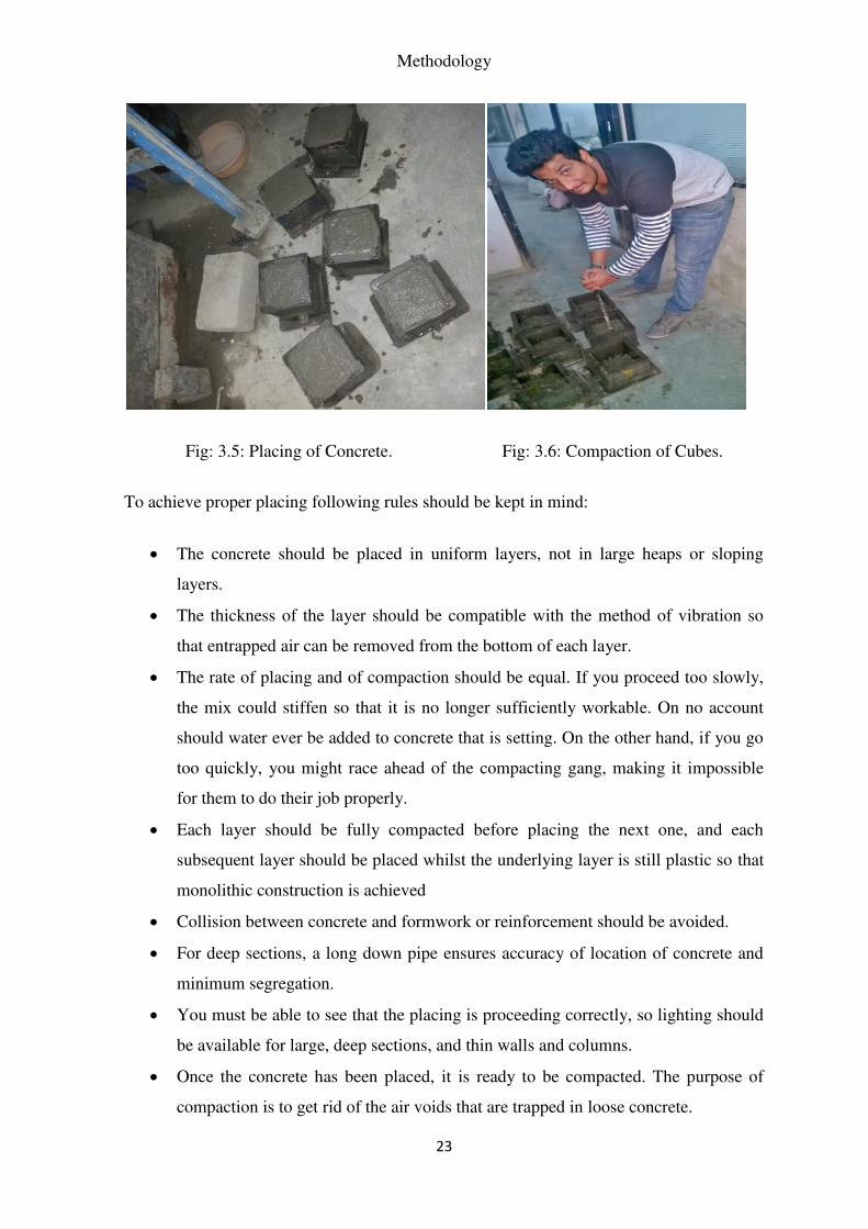
Fig: 3.5: Placing of Concrete. Fig: 3.6: Compaction of Cubes.
To achieve proper placing following rules should be kept in mind:
The concrete should be placed in uniform layers, not in large heaps or sloping
layers.
The thickness of the layer should be compatible with the method of vibration so
that entrapped air can be removed from the bottom of each layer.
The rate of placing and of compaction should be equal. If you proceed too slowly,
the mix could stiffen so that it is no longer sufficiently workable. On no account
should water ever be added to concrete that is setting. On the other hand, if you go
too quickly, you might race ahead of the compacting gang, making it impossible
for them to do their job properly.
Each layer should be fully compacted before placing the next one, and each
subsequent layer should be placed whilst the underlying layer is still plastic so that
monolithic construction is achieved
Collision between concrete and formwork or reinforcement should be avoided.
For deep sections, a long down pipe ensures accuracy of location of concrete and
minimum segregation.
You must be able to see that the placing is proceeding correctly, so lighting should
be available for large, deep sections, and thin walls and columns.
Once the concrete has been placed, it is ready to be compacted. The purpose of
compaction is to get rid of the air voids that are trapped in loose concrete.

Chapter 3
24
3.7.1. Necessity of Compaction:
It is important to compact the concrete fully because:
Air voids reduce the strength of the concrete. For every 1% of entrapped air, the
strength falls by somewhere between 5 and 7%. This means that concrete
containing a mere 5% air voids due to incomplete compaction can lose as much as
one third of its strength.
Air voids increase concrete's permeability. That in turn reduces its durability. If the
concrete is not dense and impermeable, it will not be watertight. It will be less able
to withstand aggressive liquids and its exposed surfaces will weather badly.
Moisture and air are more likely to penetrate to the reinforcement causing it to rust.
Air voids impair contact between the mix and reinforcement (and, indeed, any
other embedded metals). The required bond will not be achieved and the reinforced
member will not be as strong as it should be.
Air voids produce blemishes on struck surfaces. For instance, blowholes and
honeycombing might occur.
Summing up, fully compacted concrete is dense, strong and durable; badly compacted
concrete will be porous, weak and prone to rapid deterioration. Sooner or later it will have
to be repaired or replaced. It pays, therefore, to do the job properly in the first place. Stiff
mixes contain far more air than workable ones. That is one of the reasons why a low-slump
concrete requires more compactive effort than one with a higher slump - the compaction
needs to continue for a longer time, or more equipment has to be used.
Even air-entrained concrete needs to be compacted to get rid of entrapped air voids. The
difference between air voids and entrained air bubbles should be noted at this stage. The
air bubbles that are entrained are relatively small and spherical in shape, increase the
workability of the mix, reduce bleeding, and increase frost resistance. Entrapped air on the
other hand tends to be irregular in shape and is detrimental to the strength of the mix. It is
to remove this air that the concrete must be properly compacted. There is little danger that
compaction will remove the minute air bubbles that have been deliberately entrained, since
they are so stable.

Methodology
25
3.7.2. Methods of Compaction of concrete
a. Vibration:
To compact concrete you apply energy to it so that the mix becomes more fluid. Air
trapped in it can then rise to the top and escape. As a result, the concrete becomes
consolidated, and you are left with a good dense material that will, after proper curing,
develop its full strength and durability.
Vibration is the next and quickest method of supplying the energy. Manual techniques
such as rodding are only suitable for smaller projects. Various types of vibrator are
available for use on site.
b. Poker Vibrators
The poker, or immersion, vibrator is the most popular of the appliances used for
compacting concrete. This is because it works directly in the concrete and can be moved
around easily.
c. Sizes:
Pokers with diameters ranging from 25 to 75mm are readily available, and these are
suitable for most reinforced concrete work. Larger pokers are available - with diameters up
to 150mm - but these are for mass concrete in heavy civil engineering.
d. Radius of action:
When a poker vibrator is operating, it will be effective over a circle centered on the poker.
The distance from the poker to the edge of the circle is known as the radius of action.
However, the actual effectiveness of any poker depends on the workability of the concrete
and the characteristics of the vibrator itself. As a general rule, the bigger the poker and the
higher its amplitude, the greater will be the radius of action. It is better to judge from your
own observations, as work proceeds on site, the effective radius of the poker you are
operating on the concrete you are compacting. The length of time it takes for a poker
vibrator to compact concrete fully depends on:
Chapter 3
26
The workability of the concrete: the less workable the mix, the longer it must be
vibrated.
The energy put in by the vibrator: bigger vibrators do the job faster.
The depth of the concrete: thick sections take longer.
3.8. Curing of Concrete:
Definition:
Curing can be described as keeping the concrete moist and warm enough so that the
hydration of cement can continue. More elaborately, it can be described as the process of
maintaining satisfactory moisture content and a favorable temperature in concrete during
the period immediately following placement, so that hydration of cement may continue
until the desired properties are developed to a sufficient degree to meet the requirement of
service.
If curing is neglected in the early period of hydration, the quality of concrete will
experience a sort of irreparable loss. An efficient curing in the early period of hydration
can be compared to a good and wholesome feeding given to a new born baby.
3.8.1. Methods of Curing Concrete:
Concrete curing methods may be divided broadly into four categories:
a. Water curing
b. Membrane curing
c. Application of heat
d. Miscellaneous

Methodology
27
a. Water Curing:
This is by far the best method of curing as it satisfies all the requirements of curing,
namely, promotion of hydration, elimination of shrinkage and absorption of the heat of
hydration. It is pointed out that even if the membrane method is adopted, it is desirable that
a certain extent of water curing is done before the concrete is covered with membranes.
Water curing can be done in the following ways:
i. Ponding.
ii. Spraying or Fogging
iii. Wet Covering
The precast concrete items are normally immersed in curing tanks for certain duration.
Pavement slabs, roof slab etc. are covered under water by making small ponds. Vertical
retaining wall or plastered surfaces or concrete columns etc. are cured by spraying water.
In some cases, wet coverings such as wet gunny bags, hessian cloth, jute matting, straw
etc., are wrapped to vertical surface for keeping the concrete wet. For horizontal surfaces
saw dust, earth or sand are used as wet covering to keep the concrete in wet condition for a
longer time so that the concrete is not unduly dried to prevent hydration.
i. Ponding: This is the most common and inexpensive method of curing flat
surfaces such as floor slabs, flat roofs, pavements and other horizontal
surfaces. A dike around the edge of the slab, which may be sub-divided into
smaller dikes, is erected and water is filled to create a shallow pond. Care
must be taken to ensure that the water in the pond does not dry up, as it may
lead to an alternate drying and wetting condition.
ii. Sprinkling, fogging & mist curing: Using a fine spray or fog or mist of
water can be an efficient method of supplying water to the concrete surface
especially during hot weather, which helps to reduce the temperature of
concrete, eventually conserving moisture inside the body of concrete.
iii. Wet coverings: Water absorbent fabrics such as hessian, burlaps, cotton
mats, rugs etc. may be used to maintain water on the concrete surface by
completely covering the surface immediately after the concrete has set.
Chapter 3
28
They must be continuously kept moist to prevent the fabric from absorbing
water from the body of concrete, due to capillary action. In rural areas,
straw sprinkled with water regularly can be used to cure concrete. Care
must be taken when using straw, as dry straw can fly away if the wind
velocity is very high and it can also cause fire hazards. Moist earth, sand or
saw dust can be used to cure horizontal surfaces. However, staining of the
surface can occur due to certain organic matter, if present.
b. Impermeable Membrane Curing:
Formwork leaving the formwork in place during the early age of concrete is one of
the most efficient methods of curing, especially for columns. The formwork
reduces considerably.
Plastic sheeting Plastic sheets form an effective barrier to control the moisture
losses from the surface of the concrete, provided they are secured in place and are
protected from damage. They must be placed immediately after the final set of
concrete without causing any damage to the surface. On flat surfaces like slabs,
pavements, etc they must be properly secured to the surface and must extend
beyond the edges of the slab, so that they are not blown away by gusty winds. Also
foot, machinery and vehicular traffic must be avoided over the plastic sheet, to
prevent damage. For vertical surfaces, the member must be thoroughly wrapped
and the edges taped to prevent loss of moisture from the concrete surface. Plastic
sheet may be transparent or colored depending upon the ambient temperature
prevailing during that particular season. The efficiency of this system can be
enhanced by flooding the concrete surface of the slab with water, under the plastic
sheet.
Membrane curing compounds - Curing compounds are wax, acrylic and water
based liquids which are sprayed over the freshly finished concrete to form an
impermeable membrane that minimizes the loss of moisture from the concrete.
These are cost effective methods of curing where standard curing procedures are
difficult to adopt. When used to cure concrete the timing of the application is
critical for maximum effectiveness. They must be applied when the free water on
the surface has evaporated and there is no water sheen on the surface visible. Too
early application dilutes the membrane, where as too late application results in
being absorbed into the concrete. Care must be taken to avoid foot, machinery and

Methodology
29
vehicular traffic over the concrete surface to prevent damage of the coating.
For concretes with low w/c ratio, the use of curing compounds may not be suitable
for curing. When hydration takes place the relative humidity of interior concrete
drops leading to self-drying of concrete. Under such circumstances, wet curing
provides an external source of water to replenish the water utilized in the hydration
process. Curing compounds may also prevent the bond between the hardened and
the freshly placed concrete overlay. For example Curing compounds should not be
applied to two lift pavement construction. Similarly, curing compounds should not
be applied to concrete surface which will be receiving plasters, decorative &
protective paints, etc, as it affects the adhesion.
c. Steam Curing:
Steam curing is a process for accelerating the early hardening of concrete and mortars by
exposing it to steam and humidity. This type of system is most commonly used for precast
concrete products where standard products are manufactured in the factory and the
turnaround time of the formwork is very quick. In the curing chamber, the control of
temperature and humidity is of prime importance or else the concrete products are likely of
fracture, crumble and develop other problems later in their service lives. This type of
curing systems are generally adopted for railway sleepers, concrete blocks, pipes, manhole
covers, poles, pipe culverts, prestressed precast concrete products, and so forth.
Curing in Hot and cold weather requires additional attention.
d. Hot weather:
During hot weather, concrete must be protected from excessive drying and from direct sun
and wind. Curing materials which reflect sunlight to reduce concrete temperature must be
used. Water curing is recommended and care should be taken to prevent excessive stress
caused by alternative wetting and drying or by cold water on warm concrete. Framed
enclosures of canvas tarpaulins or sun shades may be used to protect the concrete from
direct sunlight.
e. Cold weather:
Some problems associated with temperature below 4o C are:

Chapter 3
30
Freezing of concrete before adequate strength is developed
Slow development of concrete strength
Thermal stresses induced by the cooling of warm concrete to cooler ambient
temperatures.
In cold weather, some procedures like heated enclosures, insulating blankets &
curing compounds may be used. The temperature of fresh concrete must be kept
above 100C by using heated raw materials and the curing shall be continued for a
longer period of time till concrete gains the desired strength.
3.8.2. Necessity of Curing:
Often questions are asked whether water can be poured over the above concrete within two
hours to prevent the drying. The associated problem is, if water is applied within say two
hours, whether it will interfere with the water/cement ratio and cause harmful effects. In
other words, question is how early water can be applied over concrete surface so that
uninterrupted and continued hydration takes place, without causing interference with the
water/cement ratio.
Fig: 3.7. Curing of Concrete
The answer is that first of all, concrete should not be allowed to dry fast in any situation.
Concrete that are liable to quick drying is required to be covered with wet gunny bag or
wet hessian cloth properly squeezed, so that the water does not drip and at the same time,
does not allow the concrete to dry.

Methodology
31
This condition should be maintained for 24 hours or at least till the final setting time of
cement at which duration the concrete will have assumed the final volume. Even if water is
poured, after this time, it is not going to interfere with the water/cement ratio.
However, the best practice is to keep the concrete under the wet gunny bag for 24 hours
and then commence water curing by way of ponding or spraying. Of course, when curing
compound is used immediately after bleeding water, if any, dries up, the question of when
to start water curing does not arise at all.
Even on the next day they make arrangements and build bunds with mud or lean mortar to
retain water. This further delays the curing. Such practice is followed for concrete road
construction by municipal corporations also. It is a bad practice. It is difficult to set time
frame how early water curing can be started.
It depends on, prevailing temperature, humidity, wind velocity, type of cement, fineness of
cement, w/c used and size of member etc. The point to observe is that, the top surface of
concrete should not be allowed to dry. Enough moisture must be present to promote
hydration.
Regarding how long to cure, it is again difficult to set a limit. Since all the desirable
properties of concrete are improved by curing, the curing period should be as long as
practical. For general guidance, concrete must be cured till it attains about 70% of
specified strength. At lower temperature curing period must be increased. Since the rate of
hydration is influenced by cement composition and fineness, the curing period should be
prolonged for concretes made with cements of slow strength gain characteristics.
3.8.3. Importance of Curing:
Curing is the process of controlling the rate and extent of moisture loss from concrete to
ensure an uninterrupted hydration of Portland cement after concrete has been placed and
finished in its final position. Curing also ensures to maintain an adequate temperature of
concrete in its early ages, as this directly affects the rate of hydration of cement and

Chapter 3
32
eventually the strength gain of concrete or mortars.
Curing of concrete must begin as soon as possible after placement & finishing and must
continue for a reasonable period of time as per the relevant standards, for the concrete to
achieve its desired strength and durability. Uniform temperature should also be maintained
throughout the concrete depth to avoid thermal shrinkage cracks. Also protective measures
to control moisture loss from the concrete surface are essential to prevent plastic shrinkage
cracks.
3.8.4. Reasons to Cure Concrete
i. There are several important reasons why one should cure concrete:
1.Concrete strength gain - Concrete strength increase with age as moisture and a
favorable temperature is present for hydration of cement. An experimental
investigation was conducted by "Cement, Concrete & Aggregates Australia"
(CCAA) and the same was published in their data sheet on "Curing of Concrete,"
which has been included in this article for reference. Figure-1 illustrates a
comparison of the strength of concrete at 180 days of moist curing with various
periods of moist curing (0, 3, 7, 14 & 28 days) and then allowing it to dry out.
From the graph below, it can be observed that concrete allowed to dry out
immediately, achieves only 40% of the strength of the same concrete water cured
for the full period of 180 days.
ii. 2. Improved durability of concrete – The durability of concrete is affected by a
number of factors including its permeability, porosity and absorptivity. Well cured
concrete can minimize thermal, plastic & drying shrinkage cracks, making concrete
more water tight, thus preventing moisture and water borne chemicals from
entering into the concrete and thereby increasing its durability.
iii. 3. Enhanced serviceability - Concrete that is allowed to dry out quickly undergoes
considerable early age shrinkage. Inadequate curing contributes to weak and dusty
surfaces having a poor abrasion resistance.
iv. 4. Improved microstructure - Material properties are directly related to their
microstructure. Curing assists the cement hydration reaction to progress steadily
and develops calcium silicate hydrate gel, which binds the aggregates leading to a
rock solid mass, makes the concrete denser, decreases the porosity and enhances
the physical and mechanical properties of concrete.

Methodology
33
2(CaO)3(SiO2) + 6H2 (CaO)3(SiO2) 3(H2O) + 3Ca(OH)2
C-S-H gel
2(CaO)2(SiO2) + 4H2O (CaO)3(SiO2) 3(H2O) + Ca(OH)2
C-S-H gel
3.8.5. Right Time to Cure Concrete
i. After concrete has been placed in its final position and during the initial set, bleed
water rises to the concrete surface as plastic settlement occurs. During this period,
if the rate of evaporation of bleed water is greater than the rising water, plastic
shrinkage of the concrete occurs. Initial mist curing is necessary to keep the surface
moist to prevent the surface from drying out.
ii. Between initial set and final set, intermediate curing would be needed if the
finishing is complete prior to final set. This may be in the form of a barrier which
prevents the loss of moisture from the concrete surface. e.g. covering the concrete
surfaces with plastic sheets, waterproof paper, etc.
iii. After final set, meticulous curing will have to be done as per the procedures
selected. e.g. water curing methods-Ponding, Misting, wet coverings with hessian
cloth, Impermeable membrane curing, Curing compounds, etc.
3.8.6. Duration of Curing:
The duration of curing of concrete depends on the grade & type of cement, mix proportion,
desired concrete strength, shape and size of the concrete member and environmental
&exposure conditions. The duration may vary from few days to a month.
IS-456:2000 provisions for duration of Curing (Indian Standard-Plain & Reinforced
concrete-Code of Practice, 4th revision, page 27)
Exposed surfaces of concrete shall be kept continuously damp or in a wet condition by
ponding or by covering with sacks, canvas, hessian or other similar material and kept
continuously wet for atleast 7 days from the date of placing, in case of Ordinary Portland
Cement (OPC) and atleast 10 days when mineral admixtures or blended cements are used.
Chapter 3
34
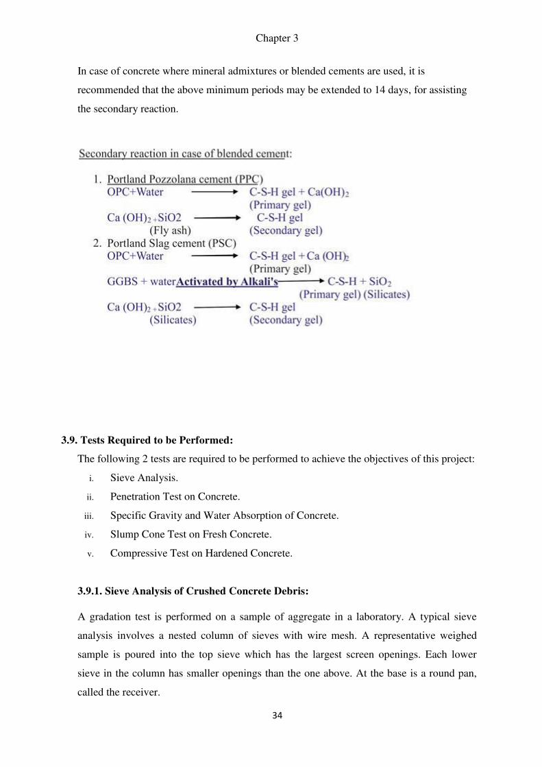
In case of concrete where mineral admixtures or blended cements are used, it is
recommended that the above minimum periods may be extended to 14 days, for assisting
the secondary reaction.
3.9. Tests Required to be Performed:
The following 2 tests are required to be performed to achieve the objectives of this project:
i. Sieve Analysis.
ii. Penetration Test on Concrete.
iii. Specific Gravity and Water Absorption of Concrete.
iv. Slump Cone Test on Fresh Concrete.
v. Compressive Test on Hardened Concrete.
3.9.1. Sieve Analysis of Crushed Concrete Debris:
A gradation test is performed on a sample of aggregate in a laboratory. A typical sieve
analysis involves a nested column of sieves with wire mesh. A representative weighed
sample is poured into the top sieve which has the largest screen openings. Each lower
sieve in the column has smaller openings than the one above. At the base is a round pan,
called the receiver.

Methodology
35
The column has been shaken typically by manual method by us. The shaker shakes the
column, usually for some fixed amount of time. After the shaking is complete the material
on each sieve is weighed. The weight of the sample of each sieve is then divided by the
total weight to give a percentage retained on each sieve.
Fig: 3.8: Sieve analysis
The size of the average particle on each sieve is then analyzed to get a cut-off point or
specific size range, which is then captured on a screen.
3.9.2. Penetration Test of Standard and Concrete Debris Mix:
3.9.2.1: Scope:
This standard covers the method for determining the setting time of concrete with
slump greater than zero, by testing mortar sieved from the concrete mixture. 1.2 In this
method of test, the initial setting time and the final setting time are the time intervals
required for the mortar sieved from the concrete mixture to reach the prescribed
penetration resistance after the initial. contact of cement and water.

Chapter 3
36
3.9.2.2: Terminology:
For the purpose of this standard, the following definitions shall apply. 2.1 Initial Setting
Time - The elapsed time, after initial contact of cement and water, required for the mortar
(sieved from the concrete) to reach a penetration resistance of 3’43 N/mm2 (35 kg f/cm2).
2.2 Final Setting Time - The elapsed time, after initial contact of cement and water,
required for the mortar ( sieved from the concrete ) to reach a penetration resistance of
26.97 N/mm2 (275 kg f/cm z).
3.9.2.3: Apparatus:
Containers for Mortar Specimens Rigid, watertight, non- absorptive, non-oiled containers,
either cylindrical or rectangular in cross- *h: section, with minimum lateral dimension 150
mm and height at least 150 mm. NOTE -The container for the mortar from the concrete
mixture a hall provide enough mortar surface for the undisturbed reading of penetration
resistance. Penetration Resistance Apparatus Spring reaction-type apparatus, graduated
from 50 N (5 kg f) to 600 N (60 kg f) in increments of 10 N (1 kg f ) or less; or hydraulic
reaction-type apparatus with pressure gauge of 700 to 900 N ( 70 to 90 kg f ) capacity,
graduated in increments of 10 N ( 1 kg f ) or less. Indications of actual needle loads by
these apparatus shall be accurate to 10 N (1 kg f ). Removable needles of 645,323,161, 65,
32 and 16 mm2 bearing areas shall be provided. Each needle shank shall be scribed
peripherally at a distance of 25 mm above the bearing face. The length of the 16 mm2
needle shall be not more than 90 mm to minimize bending. NOTE - The spring reaction-
type apparatus shall be recalibrated periodically. Pipette from the pipette or suitable
instrument for drawing off free water surface of the test specimens. Tamping Rod - Round,
straight, steel rod 16 mm in diameter and approximately 609 mm in length, having the
tamping end rounded to a hemispherical tip, of 16 mm diameter.

Methodology
37
Fig: 3.9: Penetration testing Apparatus.
3.9.2.4: Preparation of Mortar Specimen:
From the concrete mixture under test, select a representative sample of concrete of
sufficient volume to provide enough mortar to fill the test con- tainer, or containers, to a
depth of at least 140 mm. 4.2 Remove essentially all of the mortar from the sample of
concrete by sieving it through a 4.75-mm IS sieve onto a non-absorptive surface. 4.3
Thoroughly remix the mortar by hand on the non-absorptive surface and place it in the
container, or containers in layers of 50 mm each, and compact by rodding each layer. Rod
the specimen by means of the tamping rod held so as to penetrate the mortar with the
round end. Rod the mortar once for each 6.5 cm2 of top surface area of the specimen and
distribute the strokes uniformly over the cross-section of the specimen. After completion
of the rodding, tap the sides of the containers lightly with the tamping rod to close voids
left by the tamping rod and to further level the surface of the specimen. Upon completion
of specimen preparation, the mortar surface shall be at least 13 mm below the top edge of
the container to provide space for the collection and removal of bleeding water and to
avoid contact between the mortar surface and the protective covering specified.

Chapter 3
38
3.9.2.5: Storage of Mortar Specimen:
Store and maintain the specimens at the temperature, selected for testing the specimens. To
prevent excessive evaporation of moisture, keep the specimens covered and protected with
a suitable tight-fitting, water- impermeable cover for the duration of the test, except when
bleeding water is being removed or penetration tests are being made. The specimens shall
be shielded from the sun.
3.9.2.6: Procedure:
Remove bleeding water from ‘the surface of the mortar specimens just prior to making a
penetration test by means of a pipette or a suitable instrument. To facilitate collection of
bleeding water, tilt the specimen carefully to an angle of about 12” from the horizontal by
placing a block under one side 2 minutes prior to removal of the bleeding water. 7.2 Insert
a needle of appropriate size, depending upon the state of hardening of the mortar, in the
penetration resistance apparatus and bring the burning surface of the needle into contact
with the mortar surface. Gradually and uniformly apply a vertical force downward on the
apparatus until the needle penetrates the mortar to a depth of 25 mm as indicated by the
scribe mark. The time required to penetrate to the 25 mm depth shall be approximately 10
seconds. Record the force required and the time of application, measured as elapsed time
after initial contact of cement and water. In subsequent penetration tests take care to avoid
areas where the mortar has been disturbed by previous tests. The clear distance between
two needle impressions shall be at least two diameters of the needle being used, but not
less than 13 mm. The clear distance between any needle impression and the side of the
container shall be not less than 25 mm. 7.3 Make penetration tests at hourly intervals for
normal mixtures and normal temperatures, the initial test being made after an elapsed time
of 3 to 4 h. For accelerated mixtures or high temperatures, it may be advisable to make the
initial test after an elapsed time of 1 or 2 h and subsequent tests at + h intervals. For low-
temperature conditions or retarded concrete mixtures, the initial penetration test may be
deferred for an elapsed time of 4 to 6 h, and perhaps longer. Subsequent tests may be made
at intervals of 1 h, unless the rate of increase in penetration resistance indicates that shorter
intervals are desirable. 7.4 Not less than six penetration resistance determinations shah be
made in each rate of hardening test and the time intervals between penetration resistance
determinations shall be such as to give a satisfactory rate of hardening curve, as indicated
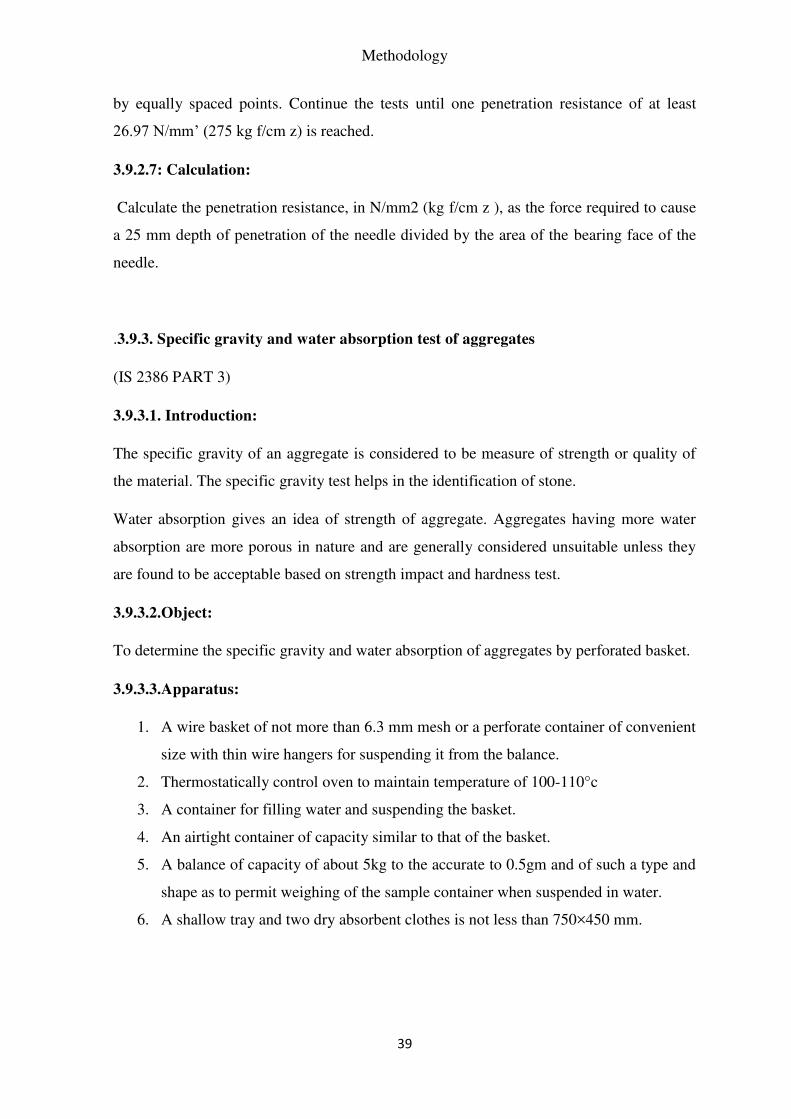
Methodology
39
by equally spaced points. Continue the tests until one penetration resistance of at least
26.97 N/mm’ (275 kg f/cm z) is reached.
3.9.2.7: Calculation:
Calculate the penetration resistance, in N/mm2 (kg f/cm z ), as the force required to cause
a 25 mm depth of penetration of the needle divided by the area of the bearing face of the
needle.
.3.9.3. Specific gravity and water absorption test of aggregates
(IS 2386 PART 3)
3.9.3.1. Introduction:
The specific gravity of an aggregate is considered to be measure of strength or quality of
the material. The specific gravity test helps in the identification of stone.
Water absorption gives an idea of strength of aggregate. Aggregates having more water
absorption are more porous in nature and are generally considered unsuitable unless they
are found to be acceptable based on strength impact and hardness test.
3.9.3.2.Object:
To determine the specific gravity and water absorption of aggregates by perforated basket.
3.9.3.3.Apparatus:
1. A wire basket of not more than 6.3 mm mesh or a perforate container of convenient
size with thin wire hangers for suspending it from the balance.
2. Thermostatically control oven to maintain temperature of 100-110°c
3. A container for filling water and suspending the basket.
4. An airtight container of capacity similar to that of the basket.
5. A balance of capacity of about 5kg to the accurate to 0.5gm and of such a type and
shape as to permit weighing of the sample container when suspended in water.
6. A shallow tray and two dry absorbent clothes is not less than 750×450 mm.
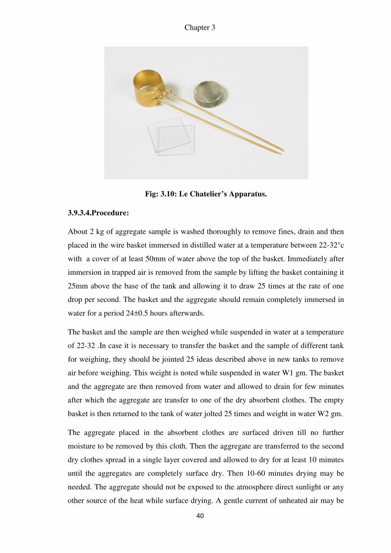
Chapter 3
40
Fig: 3.10: Le Chatelier’s Apparatus.
3.9.3.4.Procedure:
About 2 kg of aggregate sample is washed thoroughly to remove fines, drain and then
placed in the wire basket immersed in distilled water at a temperature between 22-32°c
with a cover of at least 50mm of water above the top of the basket. Immediately after
immersion in trapped air is removed from the sample by lifting the basket containing it
25mm above the base of the tank and allowing it to draw 25 times at the rate of one
drop per second. The basket and the aggregate should remain completely immersed in
water for a period 24±0.5 hours afterwards.
The basket and the sample are then weighed while suspended in water at a temperature
of 22-32 .In case it is necessary to transfer the basket and the sample of different tank
for weighing, they should be jointed 25 ideas described above in new tanks to remove
air before weighing. This weight is noted while suspended in water W1 gm. The basket
and the aggregate are then removed from water and allowed to drain for few minutes
after which the aggregate are transfer to one of the dry absorbent clothes. The empty
basket is then returned to the tank of water jolted 25 times and weight in water W2 gm.
The aggregate placed in the absorbent clothes are surfaced driven till no further
moisture to be removed by this cloth. Then the aggregate are transferred to the second
dry clothes spread in a single layer covered and allowed to dry for at least 10 minutes
until the aggregates are completely surface dry. Then 10-60 minutes drying may be
needed. The aggregate should not be exposed to the atmosphere direct sunlight or any
other source of the heat while surface drying. A gentle current of unheated air may be
Methodology
41
used during first 10 minutes to accelerate the drying of aggregate surface. A surface
dry aggregate is then weighed W3gm. The aggregate is placed in shallow tray and kept
in an oven maintained a temperature of 110°c for 24 hours. It is removed form the
oven. Cooled in an airtight container of weighed W4 gm. Atleast two days should be
carried out but not concurrently.
3.9.3.5. Calculations:
Weight of saturated aggregate suspended in water with the basket= W1 gm
Weight of basket suspended in water = W2 gm
Weight of saturated aggregate in water = (W1-W2) = WS gm
Weight of saturated surface dry aggregate in air = W4 gm
Weight of water equal to the volume of aggregate = (W3 – WS) gm
1. Specific gravity = � ℎ � � � � ℎ � �
= � � −�� =
� � − � −�
2. Apparent specific gravity = � ℎ � � � � ℎ � � � �� � � � �
=� � −�� =
� � − � −�
3. Water Absorption = percent by weight of water absorbed in terms oven dried
weight of
Aggregates.
= � −� �
3.9.4. Slump Cone Tests on Fresh Concrete

Chapter 3
42
This test is performed to measure consistency or workability of fresh concrete,
where the nominal maximum size of aggregate does not exceed 38 mm using slump test
apparatus.
Reference Code: IS: 1199 – 1959 – Method of sampling and analysis of concrete.
3.9.4.1. Equipments and Apparatus:
Slump cone (Height = 30 cm, Base dia = 20 cm, Top dia = 10 cm)
Tamping rod (Length = 60 cm, Dia = 16 mm)
Fig: 3.11: Slump Cone Test Apparatus
3.9.4.2. Procedure:
1. The internal surface of the mould is thoroughly cleaned and freed from superfluous
moisture before commencing the test. And if the cone is in completely dry condition
then dampen it using a damp cloth.
2. The mould is then placed on a smooth, horizontally levelled rigid and non-absorbent
surface such as a rigid plate. It is held firmly in place during filling by the operator by
standing on the two foot pieces provided in the slump cone.
3. The mould is filled by concrete in four layers, each approximately one-quarter of
height of the mould, and each layer is tamped down with 25 strokes of tamping rod
with pointed end in a uniform manner.

Methodology
43
4. After tamping the top layer, the concrete is struck off level with a trowel and any
mortar leaked out between the mould and base plate is cleaned away.
5. The mould is then removed from the concrete immediately by raising it slowly and
carefully in a vertical direction.
3.9.4.3. Report: Report the slump in terms of millimeters to the nearest 5 mm of
subsidence of the specimen during the test.
3.9.4.4. Notes to Remember:
If concrete consists of aggregates of size larger than 38 mm, then that concrete should
be first sieved on a 38 mm sieve. Concrete passing the 38 mm sieve is then tested for
workability using the slump cone apparatus of above mentioned dimension.
If the slump test shows shearing of the concrete mass or become completely
collapsed, then the test results are invalid and the slump test is repeated. See Fig. 1.2.
After completion of the slump test, to get an idea on cohesiveness of concrete, tap
slightly the outer perimeter of the slumped concrete. If it subsides further, then it is an
indication of good quality concrete having required cohesiveness. But if it gets
collapsed or shears away then the concrete lacks cohesiveness and this is an indication
of poor quality concrete.
3.9.4.5. Safety and Precautions:
Use hand gloves & shoes while testing.
Equipment should be cleaned thoroughly before testing & after testing.
The apparatus should remain free from vibrations during the test.
Petroleum jelly should be applied to the mould.
3.9.5. Compression Test on Concrete:
It is the most common test conducted on hardened concrete as it is an easy test to
perform and also most of the desirable characteristic properties of concrete are
qualitatively related to its compressive strength. The compression test is carried out on
specimens cubical in shape of the size 150 × 150 × 150 mm. The test was carried out in the
following steps:
First of all the mould preferably of cast iron, is used to prepare the specimen of size
150 × 150 × 150 mm. During the placing of concrete in the moulds it is compacted with
the tamping bar with not less than 35 strokes per layer. Then these moulds are placed on
the vibrating table and are compacted until the specified condition is attained. After 24
hours the specimens are removed from the moulds and immediately submerged in clean

Chapter 3
44
fresh water. After 28 days the specimens are tested under the load in a compression testing
machine.
3.9.5.1. Procedure:
1. Representative samples of concrete shall be taken and used for casting cubes 15 cm x
15 cm x 15 cm or cylindrical specimens of 15 cm dia x 30 cm long.
2. The concrete shall be filled into the moulds in layers approximately 5 cm deep. It
would be distributed evenly and compacted either by vibration or by hand tamping.
After the top layer has been compacted, the surface of concrete shall be finished level
with the top of the mould using a trowel; and covered with a glass plate to prevent
evaporation.
3. The specimen shall be stored at site for 24+ ½ h under damp matting or sack. After
that, the samples shall be stored in clean water at 27+20C; until the time of test. The
ends of all cylindrical specimens that are not plane within 0.05 mm shall be capped.
4. Just prior to testing, the cylindrical specimen shall be capped with sulphur mixture
comprising 3 parts sulphur to 1 part of inert filler such as fire clay.
5. Specimen shall be tested immediately on removal from water and while they are still
in wet condition.
6. The bearing surface of the testing specimen shall be wiped clean and any loose
material removed from the surface. In the case of cubes, the specimen shall be placed
in the machine in such a manner that the load cube as cast, that is, not to the top and
bottom.
7. Align the axis of the specimen with the steel plate, do not use any packing.
8. The load shall be applied slowly without shock and increased continuously at a rate of
approximately 140 kg/sq.cm/min until the resistance of the specimen to the increased
load breaks down and no greater load can be sustained. The maximum load applied to
the specimen shall then be recorded and any unusual features noted at the time of
failure brought out in the report.
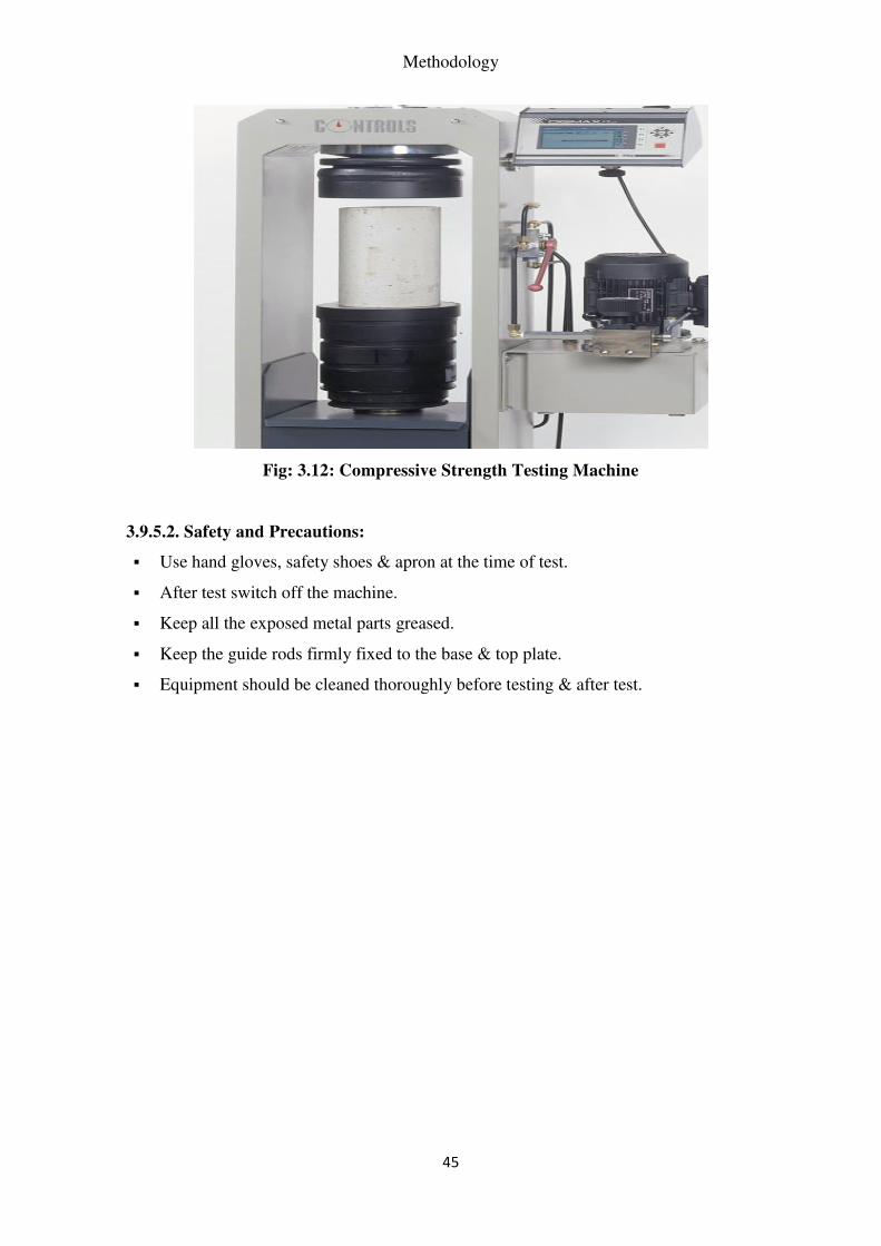
Methodology
45
Fig: 3.12: Compressive Strength Testing Machine
3.9.5.2. Safety and Precautions:
Use hand gloves, safety shoes & apron at the time of test.
After test switch off the machine.
Keep all the exposed metal parts greased.
Keep the guide rods firmly fixed to the base & top plate.
Equipment should be cleaned thoroughly before testing & after test.

48
Chapter 4
Results and Discussions
4.1. Introduction:
Based on the methodologies discussed in the previous chapter, sieve analysis was carried
out on aggregates larger than 10 mm and on aggregates smaller than 10 mm. Specific gravity and
water absorption test is carried out on the aggregates and is checked for IS standards. Penetration
test was also carried out on standard and debris concrete mix. The particle size distribution and
mix design of the different mixes has also been presented in this chapter. And finally the
workability by slump cone test and compressive strength results from compressive strength test
are also added and discussed here. All the above are presented separately for M20 and M25
grades in the formats below.
4.2. Results of M25 Mix:
The results of the various tests carried out on M25 Grade of Concrete Mix are presented
in the tables below and compared with the standard values as and when required.
4.2.1. Sieve Analysis:
Table 4.1: Sieve Analysis of Aggregate Larger than 10mm (as per IS 2386 Part 1) for M25
grade of concrete
IS Sieve
Size
(mm)
Test No 1 Test No 2 Mean of
percent
retained
Cumulative percent
Wt.
retained
Percent
retained
Wt.
retained
Percent
retained
Retained
Passing

Chapter 4
49
(gm) (gm)
40 0 0 0 0 0 100
25 241.4 11 257.3 13 12 12 88
20 266.6 12 329.1 16 14 26 74
12.5 368.2 17 91.6 5 11 37 63
10 128.4 59 1330.3 6.5 62 99 01
4.75 - - - - - - -
2.36 - - - - - - -
Pan 26.4 01 23.3 1 1 100 0
Total 2187 100 2031.6 100 100
Table 4.2: Sieve Analysis of Aggregate Smaller than 10mm (as per IS 2386 Part 1) for M25
grade of concrete
IS Sieve
Size
mm
Test No 1 Test No 2 Mean of
percent
retained
Cumulative percent
Wt.
retained
(gm)
Percent
retained
Wt.
retained
(gm)
Percent
retained
Retained
Passing
10 100
4.75 495.5 55 379.8 42 49 49 51
2.36 135.4 15 135.2 15 15 64 36
1.18 132.6 15 165.8 19 17 81 19
0.6 59.1 07 88.5 10 09 90 10
0.3 37 04 65.2 07 05 95 05
0.15 15.4 02 25.2 03 02 97 03
Pan 20.9 02 33 04 03 100 00
Total 895.9 100 892.7 100 100

Results and Discussions
50
Table 4.3: Penetration Test of Standard and Concrete Debris Mix for M25 grade of
concrete
Standard mix Penetration
(mm)
Concrete Debris Mix Penetration
(mm)
1 3.8 1 4.0
2 5.0 2 5.5
3 4.5 3 5.9
4 5.0 4 5.0
5 4.0 5 4.0
Average 4.46 Average 4.88
The above table shows the different values of penetration of each five specimens of the
M25 mix. The average difference of the penetration of the standard mix is 8.61% higher than the
average penetration of the concrete debris mixture. However, the penetration must be read from
the nearest ¼ in (6.4 mm). Hence, the penetration of the concrete debris mixture passed the
allowed penetration for mortar.
Table 4.4: Design Stipulation for M25 Grade Concrete
Characteristic strength at 28 days (N/mm2) 25
Workability, slump at placing point (mm) 100±20
Nominal maximum size of aggregate (mm) 40
Table 4.5: Mix Proportions for M25 Grade of Concrete
Data on Ingredients Source Specific
Gravity
DLBD
(kg/l)
Water
Absorption (%)
Quantity
(kg/cum)
Cement Ambuja
OPC 53
3.00 -- -- 320
Fine aggregates N.A 2.57 -- 5.16 697
Coarse aggregates N.A 2.54 -- 5.36 1187
Water Local -- 160

Chapter 4
51
Admixture CAC
SF 65
1.23 3.20
Water/cementitious 0.50 Aggregate /
Cementitious
5.89 -
Table 4.6: Particle Size Distribution of Fine and Coarse Aggregates for M25 grade of
concrete
IS Sieve NS CS 10 mm 20 mm
40 100 -- -- 95
25 100 -- -- 95
20 100 -- -- 29
12.5 100 -- -- 22
10 100 -- -- 19
4.75 95 -- -- 10
2.36 81 -- -- 7
1.18 60 -- -- 4
0.6 45 -- -- 3
0.3 23 -- -- 2
0.15 5 -- -- 1
Table 4.7: Workability (Slump Cone) for M25 Grade of Concrete
Initial reading (mm) Final reading (mm)
100 80
Fig. 4.1: Slump Cone Test

Results and Discussions
52
Table 4.8: Compressive Strength of Concrete for M25 grade of Concrete
No. of Days 3 7 14 28
Average Compressive Strength
(N/mm2)
21 25.1 30 34.9
Fig. 4.2: Comparison of Compressive Strength of Standard and Recycled Concrete
(N/mm2) for M25 Grade of Concrete
From the above figure, it is evident that the compressive strength of recycled concrete is
more than that of standard concrete.
4.3. Results of M20 Mix:
The results of the various tests carried out on M20 Grade of Concrete Mix are presented
in the tables below and compared with the standard values as and when required.
4.3.1. Sieve Analysis:
Table 4.9: Sieve Analysis of Aggregate Larger than 10mm (as per IS 2386 Part 1) for M20
grade of Concrete
IS Sieve
Size
(mm)
Test No 1 Test No 2 Mean of
percent
retained
Cumulative percent
Wt.
retained
Percent
retained
Wt.
retained
Percent
retained
Retained
Passing

Chapter 4
53
(gm) (gm)
40 0 0 0 0 0 100
25 193.12 11 205.84 13 12 12 88
20 213.28 12 263.28 16 14 26 74
12.5 294.56 17 73.28 5 11 37 63
10 102.72 59 1064.24 6.5 62 99 01
4.75 - - - - - - -
2.36 - - - - - - -
Pan 21.12 01 18.64 1 1 100 0
Total 1749.6 100 1625.28 100 100
Table 4.10: Sieve Analysis of Aggregate Smaller than 10mm (as per IS 2386 Part 1) for
M20 grade of concrete
IS Sieve
Size
mm
Test No 1 Test No 2 Mean of
percent
retained
Cumulative percent
Wt.
retained
(gm)
Percent
retained
Wt.
retained
(gm)
Percent
retained
Retained
Passing
10 - - - - - - 100
4.75 396.4 55 379.8 42 49 49 51
2.36 108.32 15 135.2 15 15 64 36
1.18 106.08 15 165.8 19 17 81 19
0.6 47.28 07 88.5 10 09 90 10
0.3 29.6 04 65.2 07 05 95 05
0.15 12.32 02 25.2 03 02 97 03
Pan 16.72 02 33 04 03 100 00
Total 716.72 100 892.7 100 100
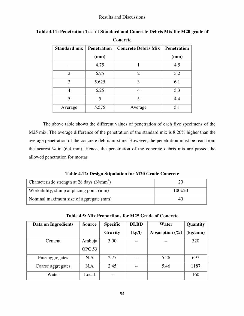
Results and Discussions
54
Table 4.11: Penetration Test of Standard and Concrete Debris Mix for M20 grade of
Concrete
Standard mix Penetration
(mm)
Concrete Debris Mix Penetration
(mm)
1 4.75 1 4.5
2 6.25 2 5.2
3 5.625 3 6.1
4 6.25 4 5.3
5 5 5 4.4
Average 5.575 Average 5.1
The above table shows the different values of penetration of each five specimens of the
M25 mix. The average difference of the penetration of the standard mix is 8.26% higher than the
average penetration of the concrete debris mixture. However, the penetration must be read from
the nearest ¼ in (6.4 mm). Hence, the penetration of the concrete debris mixture passed the
allowed penetration for mortar.
Table 4.12: Design Stipulation for M20 Grade Concrete
Characteristic strength at 28 days (N/mm2) 20
Workability, slump at placing point (mm) 100±20
Nominal maximum size of aggregate (mm) 40
Table 4.5: Mix Proportions for M25 Grade of Concrete
Data on Ingredients Source Specific
Gravity
DLBD
(kg/l)
Water
Absorption (%)
Quantity
(kg/cum)
Cement Ambuja
OPC 53
3.00 -- -- 320
Fine aggregates N.A 2.75 -- 5.26 697
Coarse aggregates N.A 2.45 -- 5.46 1187
Water Local -- 160
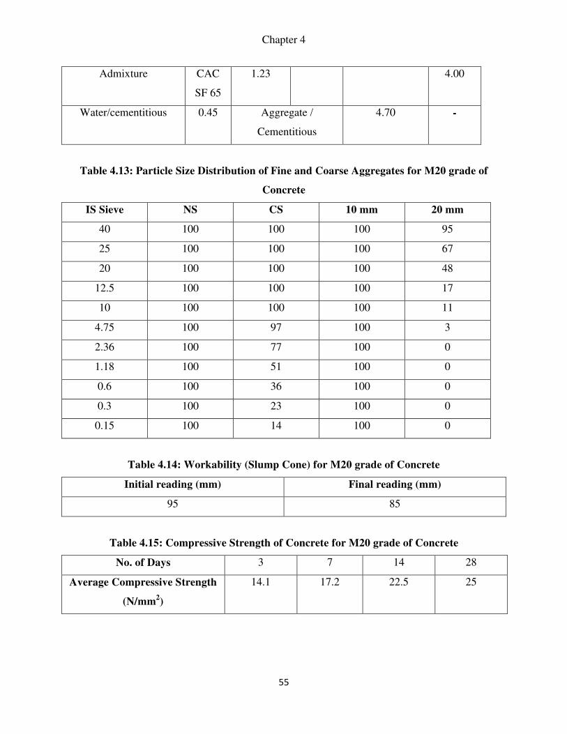
Chapter 4
55
Admixture CAC
SF 65
1.23 4.00
Water/cementitious 0.45 Aggregate /
Cementitious
4.70 -
Table 4.13: Particle Size Distribution of Fine and Coarse Aggregates for M20 grade of
Concrete
IS Sieve NS CS 10 mm 20 mm
40 100 100 100 95
25 100 100 100 67
20 100 100 100 48
12.5 100 100 100 17
10 100 100 100 11
4.75 100 97 100 3
2.36 100 77 100 0
1.18 100 51 100 0
0.6 100 36 100 0
0.3 100 23 100 0
0.15 100 14 100 0
Table 4.14: Workability (Slump Cone) for M20 grade of Concrete
Initial reading (mm) Final reading (mm)
95 85
Table 4.15: Compressive Strength of Concrete for M20 grade of Concrete
No. of Days 3 7 14 28
Average Compressive Strength
(N/mm2)
14.1 17.2 22.5 25

Results and Discussions
56
Fig. 4.3. Comparison of Compressive Strength of Standard and Recycled Concrete of M20
(N/mm2)

61
Chapter 5
Conclusion
Mix designs are prepared for M25 and M20 grade of concrete with recycled concrete as
aggregates. Sieve analysis, penetration test on concrete, specific gravity and water absorption
test of aggregates, slump cone test and compressive test on concrete is carried out.
From the results of the above mentioned tests, as presented in the above it can be
concluded that recycled concrete can be used as an aggregate as it meets all the Indian
standards specified for aggregates for concrete.
Furthermore, the concrete made with it i.e. recycled concrete also passes the standards
mentioned in the I.S. codes as far as workability is concerned. Also, the compressive strength
of recycled concrete is also more than that of standard concrete.
Therefore, it is not only environmental-friendly but also beneficial from an engineering
point of view too to use recycled concrete. It also proves to be economical than standard
concrete.
In the future scope of the project, further tests like flexural test, split tensile test, vicat
tests etc. may be performed on recycled concrete to get an in depth knowledge of the same.

62
REFERENCES
1. Thompson, J. and Bashford, H. (2012) Concrete Recycling and Utilization of Recycled
Concrete: An Investigation of the Barriers and Drivers within the Phoenix Metropolitan Area.
Construction Research Congress 2012: pp. 1682-1688.doi: 10.1061/9780784412329.169.
2. Tangchirapat, W., Rattanashotinunt, C., Buranasing, R., and Jaturapitakkul,
C. (2013). ”Influence of Fly Ash on Slump Loss and Strength of Concrete Fully
Incorporating Recycled Concrete Aggregates.” J. Mater. Civ. Eng., 25(2), 243–251.
3. Du, T., Wang, W., Lin, H., Liu, Z., and Liu, J. (2010) Experimental Study on Interfacial
Strength of the High Performance Recycled Aggregate Concrete. Earth and Space 2010: pp.
2821-2828.
4. Soleimanbeigi, A. and Edil, T. (2015). J. Geotech. Geoenviron. Eng., 141(5), 04015011.
5. Ali, M. and Arulrajah, A. (2012) Potential Use of Recycled Crushed Concrete-Recycled
Crushed Glass Blends in Pavement Subbase Applications. GeoCongress 2012: pp. 3662-
3671.
6. Purushothaman, R., Amirthavalli, R., and Karan, L. (2015). ”Influence of Treatment
Method”Compressibility of Recycled Materials for Use As Highway Embankment Fill.” s on
the Strength and Performance Characteristics of Recycled Aggregate Concrete.” J. Mater.
Civ. Eng., 27(5), 04014168.
7. Li, Y., Sun, X., and Yin, J. (2010) Mix Design of Cement-Stabilized Recycled Aggregate
Base Course Material. Paving Materials and Pavement Analysis: pp. 184-192.
8. Matias, D., de Brito, J., Rosa, A., and Pedro, D. (2014). ”Durability of Concrete with
Recycled Coarse Aggregates: Influence of Superplasticizers.” J. Mater. Civ. Eng., 26(7),
06014011.
9. IS : 1199 – 1959 – Method of sampling and analysis of concrete.
10. IS: 516-1959 – Methods of tests for strength of concrete.
11. Concrete Mix Design (http://www.engineeringcivil.com/concrete-mix-design-as-per-
indian-standard-code.html )
12. Reinforced Concrete Structures - Vol. 2 1992by Dr. B.C. Punmia and Ashok Kumar Jain.
13. “Chemistry of Cement and Concrete” by F. M. Lea.
14. “Properties of Concrete” by A.M. Neville.
15. “Concrete Technology” by D. F. Orchard.