Embed Size (px)
Citation preview
http://jcm.sagepub.com/Journal of Composite Materials
http://jcm.sagepub.com/content/46/12/1459The online version of this article can be found at:
DOI: 10.1177/0021998311420604
2012 46: 1459 originally published online 21 September 2011Journal of Composite MaterialsPaolo Feraboli, Hirohide Kawakami, Bonnie Wade, Federico Gasco, Luciano DeOto and Attilio Masini
Recyclability and reutilization of carbon fiber fabric/epoxy composites
Published by:
http://www.sagepublications.com
On behalf of:
American Society for Composites
can be found at:Journal of Composite MaterialsAdditional services and information for
http://jcm.sagepub.com/cgi/alertsEmail Alerts:
http://jcm.sagepub.com/subscriptionsSubscriptions:
http://www.sagepub.com/journalsReprints.navReprints:
http://www.sagepub.com/journalsPermissions.navPermissions:
http://jcm.sagepub.com/content/46/12/1459.refs.htmlCitations:
What is This?
- Sep 21, 2011 OnlineFirst Version of Record
- May 30, 2012Version of Record >>
at UNIV TORONTO on August 11, 2014jcm.sagepub.comDownloaded from at UNIV TORONTO on August 11, 2014jcm.sagepub.comDownloaded from
JOURNAL OFC O M P O S I T EM AT E R I A L SArticle
Recyclability and reutilization ofcarbon fiber fabric/epoxy composites
Paolo Feraboli1, Hirohide Kawakami1,2, Bonnie Wade1,Federico Gasco1, Luciano DeOto3 and Attilio Masini3
Abstract
Solid carbon fiber/epoxy laminates manufactured by liquid resin infusion of twill fabric reinforcement are recycled in a
bath of boiling sulfuric acid to separate the fibers from the matrix. The recycled reinforcement consists of long fibers
arranged in a random, entangled mat. Using the same epoxy matrix and infusion materials and process, the recycled
fibers are reutilized to manufacture solid laminates. The physical properties of the recycled laminates are evaluated by
means of pulse-echo ultrasound, visual microscopy, and fiber volume content. The average fiber volume content of the
recycled laminates is 33%, compared to the 62% of the twill laminates. The mechanical properties of the recycled
composite include tension modulus and strength, compression modulus and strength, three-point bend flexure strength,
and short beam shear strength. The properties are compared against the values of the twill reinforcement with quasi-
isotropic stacking sequence. Results show that the recycled material offers promising elastic properties and strength
values, similar to those of advanced carbon fiber sheet molding compounds, and therefore can be used as structural
material.
Keywords
recycling, liquid resin infusion, mechanical testing
Introduction
A wide range of composite material forms are findinguse in today’s aerospace, automotive, and other trans-portation industry segments.1–5 These materials arefinally fulfilling the promise of providing manufacturerswith a cost-competitive alternative to aluminum alloys.The Boeing 787 Dreamliner, due to join the world’sactive fleet by 2010, features over 50% carbon fiberreinforced polymers (CFRP) by structural weight.1
Beside the direct benefits resulting from the greater spe-cific mechanical properties, such as increased fuel effi-ciency, and reduced pollutant and acoustic emissions,other indirect advantages of a CFRP-intensive airframeare reduced maintenance requirements, and increasedpassenger comfort due to the superior fatigue- and cor-rosion-resistance characteristics of these materials.However, the introduction of composites in the primarystructure of modern aircraft presents new challenges,such as meeting crashworthiness and lightning strikeprotection requirements, and developing a mainte-nance, inspection, and repair strategy. End-of-life con-siderations are also becoming increasingly important,
because of the large volumes of parts comprised ofCFRP that are entering service. The vast majority ofCFRP for aerospace and automotive structural appli-cations consists of thermoset resins (typically epoxy andvinylester), which cannot be re-shaped or re-formedonce processed. The chemical structure of thermosets,which imparts them the desirable attributes of highmechanical properties and environmental durability,is associated to an irreversible cross-linking processthat takes place during curing. Hence, once a part is
1Automobili Lamborghini Advanced Composite Structures Laboratory,
Department of Aeronautics & Astronautics, University of Washington,
Seattle, WA, 98195-2400, USA2Japan Ministry of Defense, Tokyo, Japan3Advanced Composites Research Center, Automobili Lamborghini S.p.A.,
Sant’Agata Bolognese, Italy
Corresponding author:
Paolo Feraboli, Automobili Lamborghini Advanced Composite Structures
Laboratory, Department of Aeronautics & Astronautics, University of
Washington, Seattle, WA, 98195-2400, USA
Email: [email protected]
Journal of Composite Materials
46(12) 1459–1473
! The Author(s) 2011
Reprints and permissions:
sagepub.co.uk/journalsPermissions.nav
DOI: 10.1177/0021998311420604
jcm.sagepub.com
at UNIV TORONTO on August 11, 2014jcm.sagepub.comDownloaded from
shaped and cured, it is not easy to physically ormechanically separate the matrix from the reinforce-ment. Even if careful effort is taken to reduce produc-tion waste during manufacturing, there is still a need torecycle CFRP material in order to avoid incinerating ordisposing it in landfills.
Since the 1990s, industry has been investigating waysto recycle CFRP products.6,7 Boeing and other indus-trial organizations have come together in 2006 to estab-lish a common industry working group, Aircraft FleetRecycling Association (AFRA), with a mutually sharedcommitment to improving older fleet asset managementand fostering the recovery and reuse of aerospace mate-rials. Boeing is working with AFRA-affiliated compa-nies to develop technologies and processes capable ofrecovering CFRP parts after the end of their servicelife. The recycling of composites is normally a two-step procedure that involves first, a mechanical separa-tion process of composites from other aircraft materialsduring an aircraft’s retirement, and second, a recyclingprocess that recovers fibers of sufficient quality so thatthey can be re-introduced as a materials source inmanufacturing. To date, several recycling technologieshave been suggested for aerospace-grade CFRP mate-rials,8–10 which can be broadly divided into mechanical,thermal, and chemical processing. In mechanical pro-cessing, the cured parts undergo crushing in a series ofmills, through which the material is reduced to particlesranging in size from 50 mm to 10mm. In this process, allthe constituents of the original CFRP appear in theresulting recyclate, which is therefore a mixture ofmatrix, and reinforcement. These recyclates are typi-cally reutilized as powder fillers in new composites,not for structural applications. For example, theyhave been used to replace calcium carbonate in com-mercial-grade sheet molding compounds (SMC) orbulk molding compounds (BMC), the advantage ofthe recyclates being that they are lighter than the mate-rials they replace.
In thermal processing, it is possible to separate thefibers from the matrix, since the fibers have the mostrecoverable value in a CFRP. The bulk of the efforts todate have focused on pyrolysis and vacuum pyrolysis asthe primary process to extract fibers for reutiliza-tion.8–12 Heat is applied in the absence of oxygen, typ-ically in furnaces using inert gases or under vacuum.Typical temperatures of 500�C and 600�C require sev-eral hours for the pyrolysis to take place. Single-fibermechanical tests seem to show that contradicting resultshave been obtained, with some authors reporting moreor less degradation in strength. Milled Carbon Ltd6–8
uses a pyrolytic continuous flow process to burn off theresin and additives and separating the fibers, which canthen be processed by chopping or milling for variousapplications. Pyrolysis was initially deemed a viable
technology but later discarded as the primary processbecause at a temperature of 500�C, the carbon fibersretain oxidation residue or char.
Another thermal process being proposed is catalyticconversion, whereby a depolymerizing catalyst is usedto convert the cured resin into low–molecular-weighthydrocarbons.6–8 Adherent Technologies Inc. uses aheat transfer fluid (e.g., phenol), which is heatedbetween 150�C and 300�C, to remove the bulk of theresin and some contaminants. Vacuum pyrolysis is usedas posttreatment to eliminate the remaining resin andcontaminants, and achieve 99% purity. The process,though still in the early phases of development byAdherent Technologies, yields more pure carbon fibersthan pyrolysis. However, challenges arise if the partscontain scrap contaminants (such as metal, paint,wires), which are typically present in all structures.
Within the framework of AFRA, shredded compos-ite scrap from retired or damaged Boeing F/A-18 hor-izontal stabilizers was sent to both Milled Carbon andAdherent Technologies.6–8 The reclaimed AS4 fibersunderwent visual and X-ray surface quality assessmentplus single-fiber mechanical property testing. Therecycled fibers were chopped and successfully incorpo-rated into SMC, BMC, or as resin injection moldingfeedstock, and incorporated into fiber preforms forthe compression molding of an automotive component(Corvette C6 fender well).
A third type of thermal processing being proposed atthe laboratory scale uses fluidized bed treatments orsupercritical fluid treatments to successfully separatethe matrix from the fibers. In the fluidized bed treat-ment,8,9 the scrap composite is placed in a bed of silicasand fluidized with heated air at temperatures of 450–500�C. During this thermal process, the polymer matrixmaterial volatizes leaving recovered carbon fibers,which are separated through a cyclone from the gasstream. In the supercritical fluid treatment,13 which isa thermal and chemical process, the pieces of materialto be recycled (approximately 25mm long) areinfringed by a supercritical flow (e.g., propanol orglycol), at temperatures between 450�C and 500�C,pressure of 50 bars, and velocities up to 1m/s, whichremoves the epoxy resin from the surface of the fibers.The recycled product is fluffy and random, and com-prises individual fiber filaments with minimal contami-nation and mean length from 6 to 10mm. Althoughprocessed in air, the carbon fibers seem to show negli-gible oxidation, and small reduction in surface oxygencontent, indicating a good potential for subsequentbonding to a polymer matrix. The fibers exhibit a strengthdegradation of 20%, while the modulus remains unaf-fected. Advantages of the fluidized bed process is that itis suitable to process parts containing mechanicalinserts, surface paints, and foam cores. The recyclates
1460 Journal of Composite Materials 46(12)
at UNIV TORONTO on August 11, 2014jcm.sagepub.comDownloaded from
could be utilized as reinforcement for nonstructuralcomposite applications such as BMC or nonwovenveils.
Microwave, thermal shock, and molten salt bathprocesses have also been used with partial success,but they have a tendency to produce recycled fiberswith residues of resin or other contaminants on thesurface.8,10
Limited effort has been directed toward chemicalprocessing. Little success was achieved in Jody et al.10
where a glycol/water solution at 240�C was used totreat composite scrap containing a urethane-based sub-strate. A more successful approach was conducted inref.,14 where neat epoxy resin and epoxy-based compos-ites were dissolved in a solution of nitric acid at tem-perature 80�C and concentrationof 4M (mol/L). Theextract was then neutralized and utilized subsequentlyfor repolymerization. The study showed that it is pos-sible to recover the epoxy resin following chemical pro-cessing, and the thermal and mechanical tests show thatstrength and glass transition temperature for therecycled resin are much higher than the pristine resindue to a higher density network structure. Anotherpromising method of recycling of carbon fibers fromcarbon/epoxy composites with a nitric acid solutionwas demonstrated in Liu et al.15 Three variables werecontrolled during the experiment: decomposition tem-perature (90�C), acid solution concentration (8M), andratio of specimen weight to acid solution volume(6 g : 100mL). The epoxy matrix in the carbon/epoxycomposites was completely decomposed in 12 h. Then,the insoluble carbon fibers were separated from thesolution and washed with acetone, and dried in anoven at 60�C. The carbon fiber surface was clean,with very little contamination. Gel permeation andgas chromatography showed that the epoxy resincould entirely decompose into low-molecular-weightcompounds, with negligible contamination on thefibers. Electron probe microscopy showed no damageto the recycled carbon fibers, and single-fiber tensiontests showed that the strength loss of the recycledcarbon fibers was negligible.
A summary of the studies performed to date on thepossibility to recycle and reuse carbon fibers shows thatthe majority of the efforts call for chopping or millingof the recycled fibers, with a particular effort aimedtoward fine particulates, whiskers, and nonwoven mats.These materials are not well suited for structural appli-cations, but may be utilized for their high thermally orelectrically conductive properties. This study focuses onassessing the possibility to use reclaimed fibers forstructural applications. The reclaiming process isbased on chemical solution of the matrix, which gener-ates pure recycled fibers, without residues, contami-nants, or surface modification, unlike many of the
currently used recycling processes. The precursor is afabric, not tape as in the majority of the recycling stud-ies performed to date, and the recycling process gener-ates a mat of long, entangled, random fibers which canbe used as reinforcement without the need for second-ary chopping or milling. Finally, it proposes a directcomparison in terms of physical and mechanical prop-erties between the composites made of pristine fiberfabric and those made of the reclaimed random mat.Using the same liquid resin and infusion process tomanufacture the composite laminates with the pristineand recycled reinforcements, it is possible to extrapo-late the immediate influence of the architecture of thereinforcement on the laminate-level properties. Thesetests yield significant information on the possibility touse the recycled fibers as reinforcement for structuralapplications.
Experimental approach
Pristine material
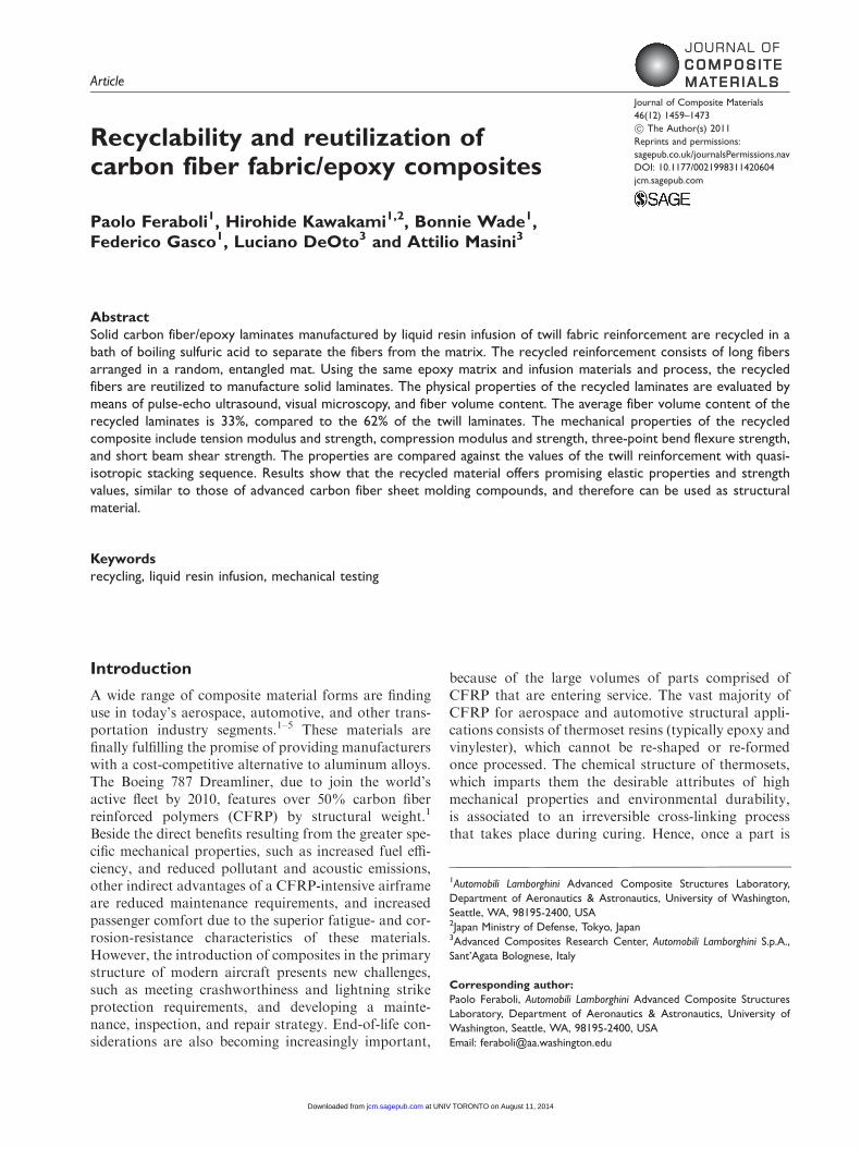
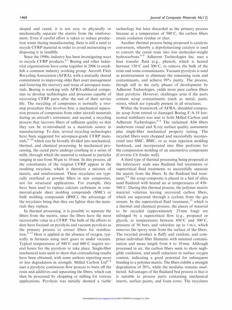
Parts are manufactured by vacuum-assisted resin trans-fer molding (VaRTM) at the Advanced CompositesResearch Center of Automobili Lamborghini S.p.A.in Sant’Agata Bolognese, Italy. The parts includeembedded surface-treated aluminum inserts for boltedconnections and are representative of typical primaryautomotive structures used by the super luxury carmanufacturer (Figure 1(A) and (B)). Flat plates arealso manufactured using the same method in order toobtain control specimens for comparative mechanicalperformance evaluation. Two different quasi-isotropicstacking sequences are investigated, yielding an upperbound and a lower bound for flexural strength. Theseare [(0/90)/(�45)]2s and [(�45)/(0/90)]2s. The reinforce-ment used is a Toray T700 carbon fiber, 12 k tow, 2� 2twill architecture, 380 gr fiber areal weight (FAW)(Figure 2(A)). The dry fabric reinforcement comes ina roll with a pre-applied binder, or tackifier, used formanual preforming or automated thermoforming(Figure 2(B)). The binder is present in a nominal con-tent of 5% by weight. It should be noted that wovenfabric comprises over 60% of Europe’s carbon fiberwaste.7 The resin used is a Huntsman two-part liquidepoxy with XB 3518 BD resin and Aradur 22962 hard-ener, in a mix ratio of 100:26 parts by weight (Table 1).The untoughened resin is a low-viscosity systemdesigned for infusion and has a pot life of over 3 h atroom temperature but only 15min at 60�C. The ovencure cycle calls for 1 h at 100�C with vacuum, followedby 2 h postcure at 140�C, giving a dry Tg of 135�C.The infusion process utilizes a distribution media,which is essential to achieve good resin distribution inthe panel. The size of the distribution media, which
Feraboli et al. 1461
at UNIV TORONTO on August 11, 2014jcm.sagepub.comDownloaded from
does not cover the entire preform, is determined by trialand error. The preform coverage by the distributionmedia is given by a complex interaction between pre-form permeability, resin viscokinetic characteristics,and part geometry, but unfortunately it can only bedetermined through experimentation. Other infusiondisposable materials include breather, perforated andnonperforated barriers, vacuum bag, and sealant. Acaul plate is not used to manufacture the panels withthe pristine twill reinforcement.
Extraction of fibers from the matrix
The automotive parts are received at the AutomobiliLamborghini Advanced Composite StructuresLaboratory at the University of Washington, Seattle,WA, where they are cut into smaller sections(200� 200mm2) for ease of processing. This step isnot required, but it is used due to the constraints ofthe experimental setup that is described below. Forindustrial applications, this step would be avoided,which would streamline the operation and yieldlonger fibers. The procedure used in this study toextract the carbon fibers from the CFRP parts is looselybased on the principles of acid digestion,16 which is a
test method utilized to determine the fiber volume con-tent Vf of a composite material. The specimen is placedin a glass acid- and heat-resistant container (i.e., a largebeaker); then sulfuric acid is added and the solutionheated on a burner to 110�C. When the solution startsto boil, hydrogen peroxide is added to accelerate thereaction and oxidize the matrix. The process takes placeunder a fume hood to remove the harmful gases.Mechanical stirring throughout the duration of theentire process is essential. If the parts are left in boilingacid without stirring, the separation of the matrix fromthe fibers does not take place, and only the surface ofthe matrix gets removed. The process typically takesseveral hours from beginning to end. When the diges-tion is complete, the container is removed from theburner in order to cool down, at which point thesolution is separated from the reinforcement througha series of filters. A vacuum pump is used to providethe aspiration force for the liquid to go through theseries of filters. Unlike the actual acid digestionstandard, which requires filters in the order of afew microns, for this purpose, it is possible to usemuch coarser filters, since the objective is to recoveronly the large fibers for subsequent reutilization. The
Figure 2. A, B. Dry fabric reinforcement and detailed view of
thermoset binder.
Figure 1. A, B. Example of parts manufactured by vacuum-
assisted resin transfer molding (VaRTM) and containing aluminum
inserts.
1462 Journal of Composite Materials 46(12)
at UNIV TORONTO on August 11, 2014jcm.sagepub.comDownloaded from
filtration process requires approximately 30min. Afterfiltration, the fibers are washed with acetone and dis-tilled water to remove traces of sulfuric acid as well asother contaminants. They are subsequently dried in anoven at 100�C for 30min.
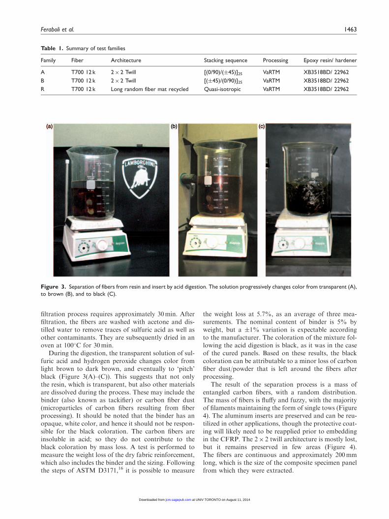
During the digestion, the transparent solution of sul-furic acid and hydrogen peroxide changes color fromlight brown to dark brown, and eventually to ‘pitch’black (Figure 3(A)–(C)). This suggests that not onlythe resin, which is transparent, but also other materialsare dissolved during the process. These may include thebinder (also known as tackifier) or carbon fiber dust(microparticles of carbon fibers resulting from fiberprocessing). It should be noted that the binder has anopaque, white color, and hence it should not be respon-sible for the black coloration. The carbon fibers areinsoluble in acid; so they do not contribute to theblack coloration by mass loss. A test is performed tomeasure the weight loss of the dry fabric reinforcement,which also includes the binder and the sizing. Followingthe steps of ASTM D3171,16 it is possible to measure
the weight loss at 5.7%, as an average of three mea-surements. The nominal content of binder is 5% byweight, but a �1% variation is expectable accordingto the manufacturer. The coloration of the mixture fol-lowing the acid digestion is black, as it was in the caseof the cured panels. Based on these results, the blackcoloration can be attributable to a minor loss of carbonfiber dust/powder that is left around the fibers afterprocessing.
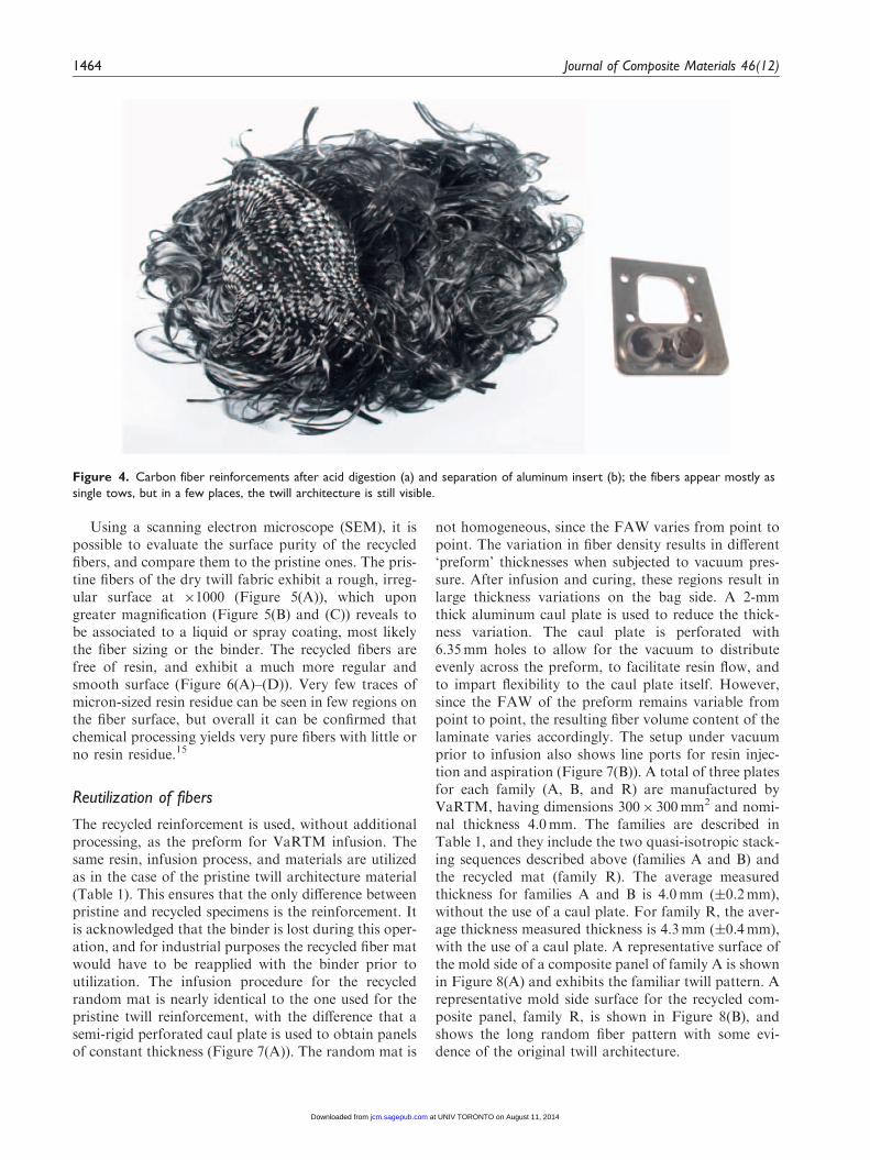
The result of the separation process is a mass ofentangled carbon fibers, with a random distribution.The mass of fibers is fluffy and fuzzy, with the majorityof filaments maintaining the form of single tows (Figure4). The aluminum inserts are preserved and can be reu-tilized in other applications, though the protective coat-ing will likely need to be reapplied prior to embeddingin the CFRP. The 2� 2 twill architecture is mostly lost,but it remains preserved in few areas (Figure 4).The fibers are continuous and approximately 200mmlong, which is the size of the composite specimen panelfrom which they were extracted.
Figure 3. Separation of fibers from resin and insert by acid digestion. The solution progressively changes color from transparent (A),
to brown (B), and to black (C).
Table 1. Summary of test families
Family Fiber Architecture Stacking sequence Processing Epoxy resin/ hardener
A T700 12 k 2� 2 Twill [(0/90)/(�45)]2S VaRTM XB3518BD/ 22962
B T700 12 k 2� 2 Twill [(�45)/(0/90)]2S VaRTM XB3518BD/ 22962
R T700 12 k Long random fiber mat recycled Quasi-isotropic VaRTM XB3518BD/ 22962
Feraboli et al. 1463
at UNIV TORONTO on August 11, 2014jcm.sagepub.comDownloaded from
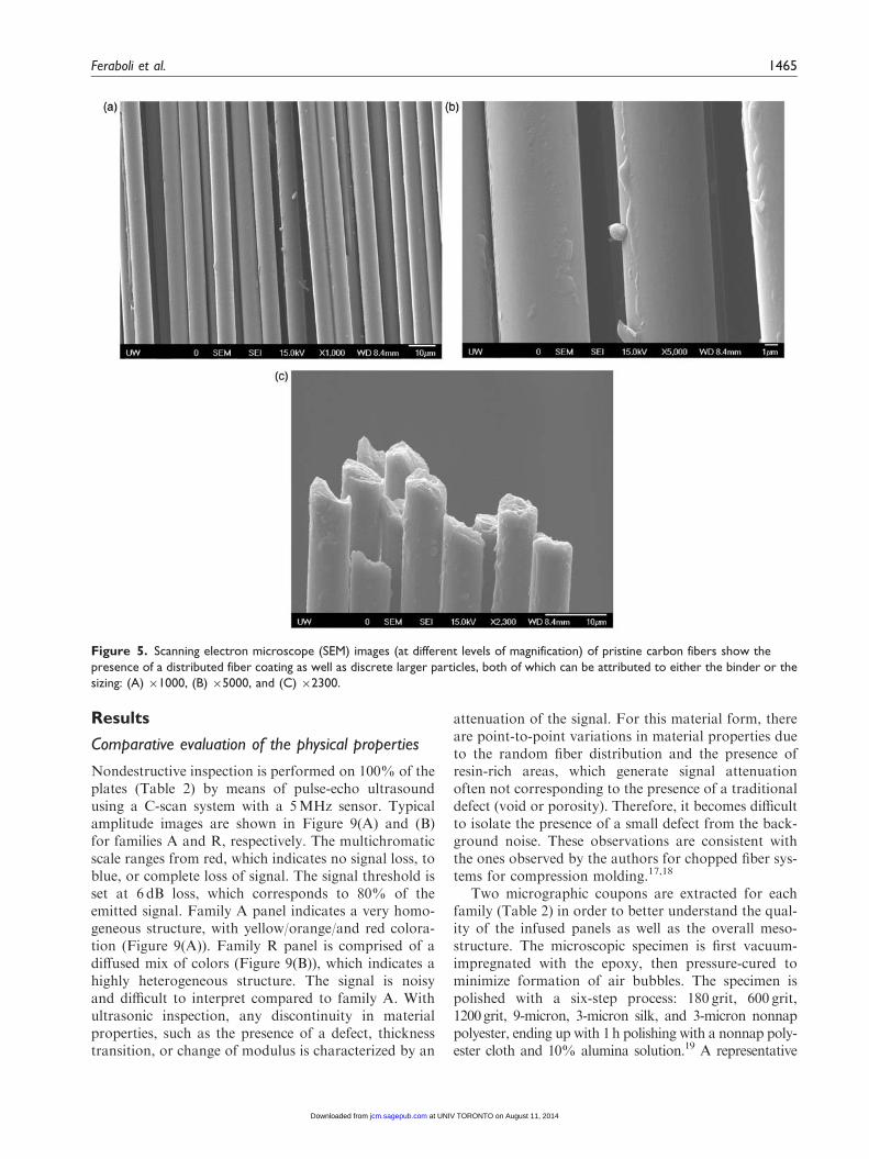
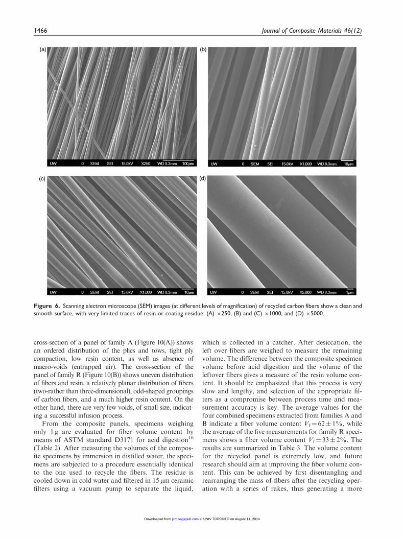
Using a scanning electron microscope (SEM), it ispossible to evaluate the surface purity of the recycledfibers, and compare them to the pristine ones. The pris-tine fibers of the dry twill fabric exhibit a rough, irreg-ular surface at �1000 (Figure 5(A)), which upongreater magnification (Figure 5(B) and (C)) reveals tobe associated to a liquid or spray coating, most likelythe fiber sizing or the binder. The recycled fibers arefree of resin, and exhibit a much more regular andsmooth surface (Figure 6(A)–(D)). Very few traces ofmicron-sized resin residue can be seen in few regions onthe fiber surface, but overall it can be confirmed thatchemical processing yields very pure fibers with little orno resin residue.15
Reutilization of fibers
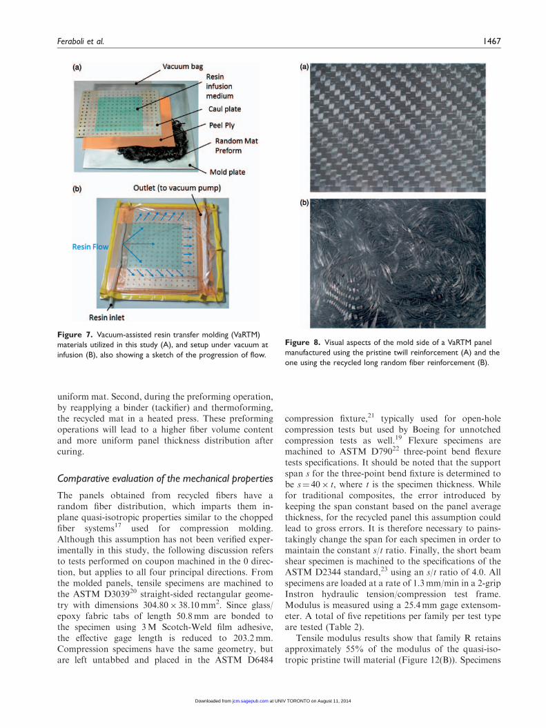
The recycled reinforcement is used, without additionalprocessing, as the preform for VaRTM infusion. Thesame resin, infusion process, and materials are utilizedas in the case of the pristine twill architecture material(Table 1). This ensures that the only difference betweenpristine and recycled specimens is the reinforcement. Itis acknowledged that the binder is lost during this oper-ation, and for industrial purposes the recycled fiber matwould have to be reapplied with the binder prior toutilization. The infusion procedure for the recycledrandom mat is nearly identical to the one used for thepristine twill reinforcement, with the difference that asemi-rigid perforated caul plate is used to obtain panelsof constant thickness (Figure 7(A)). The random mat is
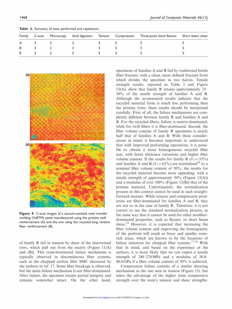
not homogeneous, since the FAW varies from point topoint. The variation in fiber density results in different‘preform’ thicknesses when subjected to vacuum pres-sure. After infusion and curing, these regions result inlarge thickness variations on the bag side. A 2-mmthick aluminum caul plate is used to reduce the thick-ness variation. The caul plate is perforated with6.35mm holes to allow for the vacuum to distributeevenly across the preform, to facilitate resin flow, andto impart flexibility to the caul plate itself. However,since the FAW of the preform remains variable frompoint to point, the resulting fiber volume content of thelaminate varies accordingly. The setup under vacuumprior to infusion also shows line ports for resin injec-tion and aspiration (Figure 7(B)). A total of three platesfor each family (A, B, and R) are manufactured byVaRTM, having dimensions 300� 300mm2 and nomi-nal thickness 4.0mm. The families are described inTable 1, and they include the two quasi-isotropic stack-ing sequences described above (families A and B) andthe recycled mat (family R). The average measuredthickness for families A and B is 4.0mm (�0.2mm),without the use of a caul plate. For family R, the aver-age thickness measured thickness is 4.3mm (�0.4mm),with the use of a caul plate. A representative surface ofthe mold side of a composite panel of family A is shownin Figure 8(A) and exhibits the familiar twill pattern. Arepresentative mold side surface for the recycled com-posite panel, family R, is shown in Figure 8(B), andshows the long random fiber pattern with some evi-dence of the original twill architecture.
Figure 4. Carbon fiber reinforcements after acid digestion (a) and separation of aluminum insert (b); the fibers appear mostly as
single tows, but in a few places, the twill architecture is still visible.
1464 Journal of Composite Materials 46(12)
at UNIV TORONTO on August 11, 2014jcm.sagepub.comDownloaded from
Results
Comparative evaluation of the physical properties
Nondestructive inspection is performed on 100% of theplates (Table 2) by means of pulse-echo ultrasoundusing a C-scan system with a 5MHz sensor. Typicalamplitude images are shown in Figure 9(A) and (B)for families A and R, respectively. The multichromaticscale ranges from red, which indicates no signal loss, toblue, or complete loss of signal. The signal threshold isset at 6 dB loss, which corresponds to 80% of theemitted signal. Family A panel indicates a very homo-geneous structure, with yellow/orange/and red colora-tion (Figure 9(A)). Family R panel is comprised of adiffused mix of colors (Figure 9(B)), which indicates ahighly heterogeneous structure. The signal is noisyand difficult to interpret compared to family A. Withultrasonic inspection, any discontinuity in materialproperties, such as the presence of a defect, thicknesstransition, or change of modulus is characterized by an
attenuation of the signal. For this material form, thereare point-to-point variations in material properties dueto the random fiber distribution and the presence ofresin-rich areas, which generate signal attenuationoften not corresponding to the presence of a traditionaldefect (void or porosity). Therefore, it becomes difficultto isolate the presence of a small defect from the back-ground noise. These observations are consistent withthe ones observed by the authors for chopped fiber sys-tems for compression molding.17,18
Two micrographic coupons are extracted for eachfamily (Table 2) in order to better understand the qual-ity of the infused panels as well as the overall meso-structure. The microscopic specimen is first vacuum-impregnated with the epoxy, then pressure-cured tominimize formation of air bubbles. The specimen ispolished with a six-step process: 180 grit, 600 grit,1200grit, 9-micron, 3-micron silk, and 3-micron nonnappolyester, ending up with 1h polishing with a nonnap poly-ester cloth and 10% alumina solution.19 A representative
Figure 5. Scanning electron microscope (SEM) images (at different levels of magnification) of pristine carbon fibers show the
presence of a distributed fiber coating as well as discrete larger particles, both of which can be attributed to either the binder or the
sizing: (A) �1000, (B) �5000, and (C) �2300.
Feraboli et al. 1465
at UNIV TORONTO on August 11, 2014jcm.sagepub.comDownloaded from
cross-section of a panel of family A (Figure 10(A)) showsan ordered distribution of the plies and tows, tight plycompaction, low resin content, as well as absence ofmacro-voids (entrapped air). The cross-section of thepanel of family R (Figure 10(B)) shows uneven distributionof fibers and resin, a relatively planar distribution of fibers(two-rather than three-dimensional), odd-shaped groupingsof carbon fibers, and a much higher resin content. On theother hand, there are very few voids, of small size, indicat-ing a successful infusion process.
From the composite panels, specimens weighingonly 1 g are evaluated for fiber volume content bymeans of ASTM standard D3171 for acid digestion16
(Table 2). After measuring the volumes of the compos-ite specimens by immersion in distilled water, the speci-mens are subjected to a procedure essentially identicalto the one used to recycle the fibers. The residue iscooled down in cold water and filtered in 15 mm ceramicfilters using a vacuum pump to separate the liquid,
which is collected in a catcher. After desiccation, theleft over fibers are weighed to measure the remainingvolume. The difference between the composite specimenvolume before acid digestion and the volume of theleftover fibers gives a measure of the resin volume con-tent. It should be emphasized that this process is veryslow and lengthy, and selection of the appropriate fil-ters as a compromise between process time and mea-surement accuracy is key. The average values for thefour combined specimens extracted from families A andB indicate a fiber volume content Vf¼ 62� 1%, whilethe average of the five measurements for family R speci-mens shows a fiber volume content Vf¼ 33� 2%. Theresults are summarized in Table 3. The volume contentfor the recycled panel is extremely low, and futureresearch should aim at improving the fiber volume con-tent. This can be achieved by first disentangling andrearranging the mass of fibers after the recycling oper-ation with a series of rakes, thus generating a more
Figure 6. Scanning electron microscope (SEM) images (at different levels of magnification) of recycled carbon fibers show a clean and
smooth surface, with very limited traces of resin or coating residue: (A) �250, (B) and (C) �1000, and (D) �5000.
1466 Journal of Composite Materials 46(12)
at UNIV TORONTO on August 11, 2014jcm.sagepub.comDownloaded from
uniform mat. Second, during the preforming operation,by reapplying a binder (tackifier) and thermoforming,the recycled mat in a heated press. These preformingoperations will lead to a higher fiber volume contentand more uniform panel thickness distribution aftercuring.
Comparative evaluation of the mechanical properties
The panels obtained from recycled fibers have arandom fiber distribution, which imparts them in-plane quasi-isotropic properties similar to the choppedfiber systems17 used for compression molding.Although this assumption has not been verified exper-imentally in this study, the following discussion refersto tests performed on coupon machined in the 0 direc-tion, but applies to all four principal directions. Fromthe molded panels, tensile specimens are machined tothe ASTM D303920 straight-sided rectangular geome-try with dimensions 304.80� 38.10mm2. Since glass/epoxy fabric tabs of length 50.8mm are bonded tothe specimen using 3M Scotch-Weld film adhesive,the effective gage length is reduced to 203.2mm.Compression specimens have the same geometry, butare left untabbed and placed in the ASTM D6484
compression fixture,21 typically used for open-holecompression tests but used by Boeing for unnotchedcompression tests as well.19 Flexure specimens aremachined to ASTM D79022 three-point bend flexuretests specifications. It should be noted that the supportspan s for the three-point bend fixture is determined tobe s¼ 40� t, where t is the specimen thickness. Whilefor traditional composites, the error introduced bykeeping the span constant based on the panel averagethickness, for the recycled panel this assumption couldlead to gross errors. It is therefore necessary to pains-takingly change the span for each specimen in order tomaintain the constant s/t ratio. Finally, the short beamshear specimen is machined to the specifications of theASTM D2344 standard,23 using an s/t ratio of 4.0. Allspecimens are loaded at a rate of 1.3mm/min in a 2-gripInstron hydraulic tension/compression test frame.Modulus is measured using a 25.4mm gage extensom-eter. A total of five repetitions per family per test typeare tested (Table 2).
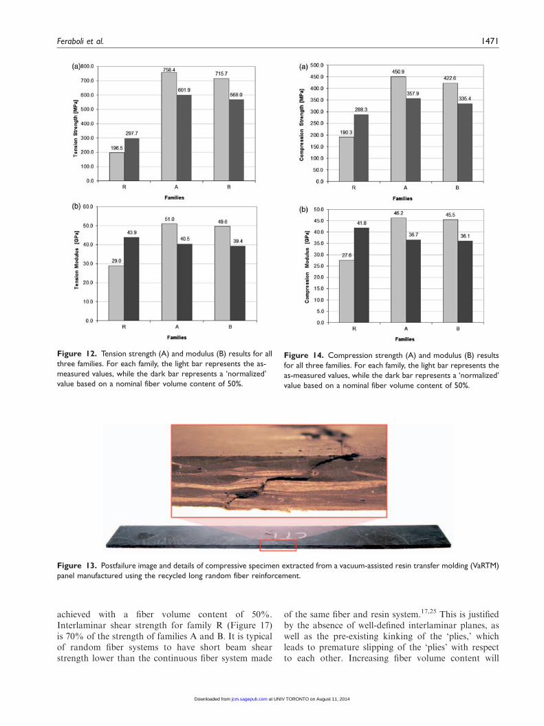
Tensile modulus results show that family R retainsapproximately 55% of the modulus of the quasi-iso-tropic pristine twill material (Figure 12(B)). Specimens
Figure 8. Visual aspects of the mold side of a VaRTM panel
manufactured using the pristine twill reinforcement (A) and the
one using the recycled long random fiber reinforcement (B).
Figure 7. Vacuum-assisted resin transfer molding (VaRTM)
materials utilized in this study (A), and setup under vacuum at
infusion (B), also showing a sketch of the progression of flow.
Feraboli et al. 1467
at UNIV TORONTO on August 11, 2014jcm.sagepub.comDownloaded from
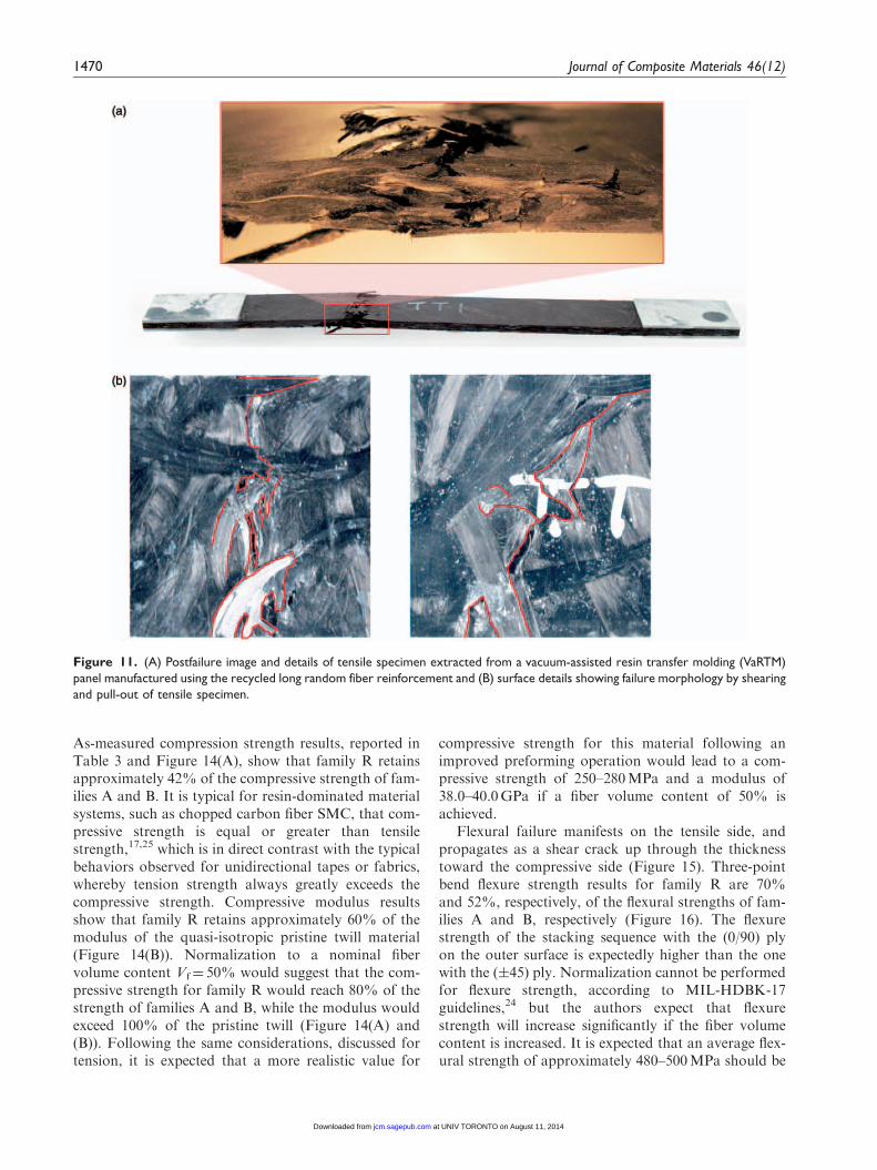
of family R fail in tension by shear of the intertwinedtows, which pull out from the matrix (Figure 11(A)and (B)). This resin-dominated failure mechanism istypically observed in discontinuous fiber systems,such as the chopped carbon fiber SMC discussed bythe authors in ref. 17. Some fiber breakage is observed,but the main failure mechanism is not fiber-dominated.After failure, the specimen retains partial integrity andremains somewhat intact. On the other hand,
specimens of families A and B fail by traditional brittlefiber fracture, with a clean, more defined fracture frontwhich divides the specimen in two halves. Tensilestrength results, reported in Table 3 and Figure12(A), show that family R retains approximately 25–30% of the tensile strength of families A and B.Although the as-measured results indicate that therecycled material form is much less performing thanthe pristine form, these results should be interpretedcarefully. First of all, the failure mechanisms are com-pletely different between family R and families A andB. For the recycled fibers, failure is matrix-dominated,while for twill fibers it is fiber-dominated. Second, thefiber volume content of family R specimens is nearlyhalf that of families A and B. With these consider-ations in mind, it becomes important to understandthat with improved preforming operations, it is possi-ble to obtain a more homogeneous recycled fibermat, with fewer thickness variations and higher fibervolume content. If the results for family R (Vf¼ 33%)and families A and B (Vf¼ 62%) are normalized24 to anominal fiber volume content of 50%, the results forthe recycled material become more appealing, with atensile strength of approximately 50% (Figure 12(A))and a modulus of over 100% (Figure 12(B)) that of thepristine material. Unfortunately, the normalizationprocess in this context cannot be used in such straight-forward manner. While tension and compression prop-erties are fiber-dominated for families A and B, theyare not so in the case of family R. Therefore, it is notcorrect to use the standard normalization process, inthe same way that it cannot be used for other nonfiber-dominated properties, such as flexure, or short beamshear.24 However, it is expected that increasing thefiber volume content and improving the homogeneityof the preform will result in fewer and smaller resin-rich areas, which are known to be the locations offailure initiation for chopped fiber systems.17,18 Withthat in mind, and based on the experience of theauthors, it is more likely that we can expect a tensilestrength of 240–270MPa and a modulus of 38.0–40.0GPa if a fiber volume content of 50% is achieved.
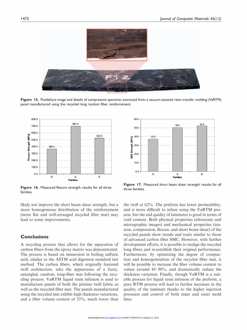
Compression failure consists of a similar shearingmechanism as the one seen in tension (Figure 13), buttakes the advantage of the higher resin compressivestrength over the resin’s tension and shear strengths.
Figure 9. C-scan images of a vacuum-assisted resin transfer
molding (VaRTM) panel manufactured using the pristine twill
reinforcement (A) and the one using the recycled long random
fiber reinforcement (B).
Table 2. Summary of tests performed and repetitions
Family C-scan Microscopy Acid digestion Tension Compression Three-point bend flexure Short beam shear
A 3 2 2 5 5 5 5
B 3 2 2 5 5 5 5
R 3 2 5 5 5 5 5
1468 Journal of Composite Materials 46(12)
at UNIV TORONTO on August 11, 2014jcm.sagepub.comDownloaded from
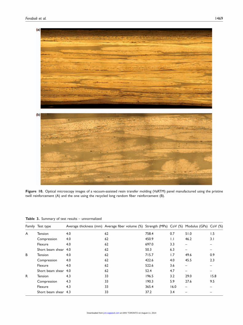
Figure 10. Optical microscopy images of a vacuum-assisted resin transfer molding (VaRTM) panel manufactured using the pristine
twill reinforcement (A) and the one using the recycled long random fiber reinforcement (B).
Table 3. Summary of test results – unnormalized
Family Test type Average thickness (mm) Average fiber volume (%) Strength (MPa) CoV (%) Modulus (GPa) CoV (%)
A Tension 4.0 62 758.4 0.7 51.0 1.5
Compression 4.0 62 450.9 1.1 46.2 3.1
Flexure 4.0 62 697.0 3.3 – –
Short beam shear 4.0 62 50.3 6.3 – –
B Tension 4.0 62 715.7 1.7 49.6 0.9
Compression 4.0 62 422.6 4.0 45.5 2.3
Flexure 4.0 62 522.6 3.6 – –
Short beam shear 4.0 62 52.4 4.7 – –
R Tension 4.3 33 196.5 3.2 29.0 15.8
Compression 4.3 33 190.3 5.9 27.6 9.5
Flexure 4.3 33 365.4 16.0 – –
Short beam shear 4.3 33 37.2 3.4 – –
Feraboli et al. 1469
at UNIV TORONTO on August 11, 2014jcm.sagepub.comDownloaded from
As-measured compression strength results, reported inTable 3 and Figure 14(A), show that family R retainsapproximately 42% of the compressive strength of fam-ilies A and B. It is typical for resin-dominated materialsystems, such as chopped carbon fiber SMC, that com-pressive strength is equal or greater than tensilestrength,17,25 which is in direct contrast with the typicalbehaviors observed for unidirectional tapes or fabrics,whereby tension strength always greatly exceeds thecompressive strength. Compressive modulus resultsshow that family R retains approximately 60% of themodulus of the quasi-isotropic pristine twill material(Figure 14(B)). Normalization to a nominal fibervolume content Vf¼ 50% would suggest that the com-pressive strength for family R would reach 80% of thestrength of families A and B, while the modulus wouldexceed 100% of the pristine twill (Figure 14(A) and(B)). Following the same considerations, discussed fortension, it is expected that a more realistic value for
compressive strength for this material following animproved preforming operation would lead to a com-pressive strength of 250–280MPa and a modulus of38.0–40.0GPa if a fiber volume content of 50% isachieved.
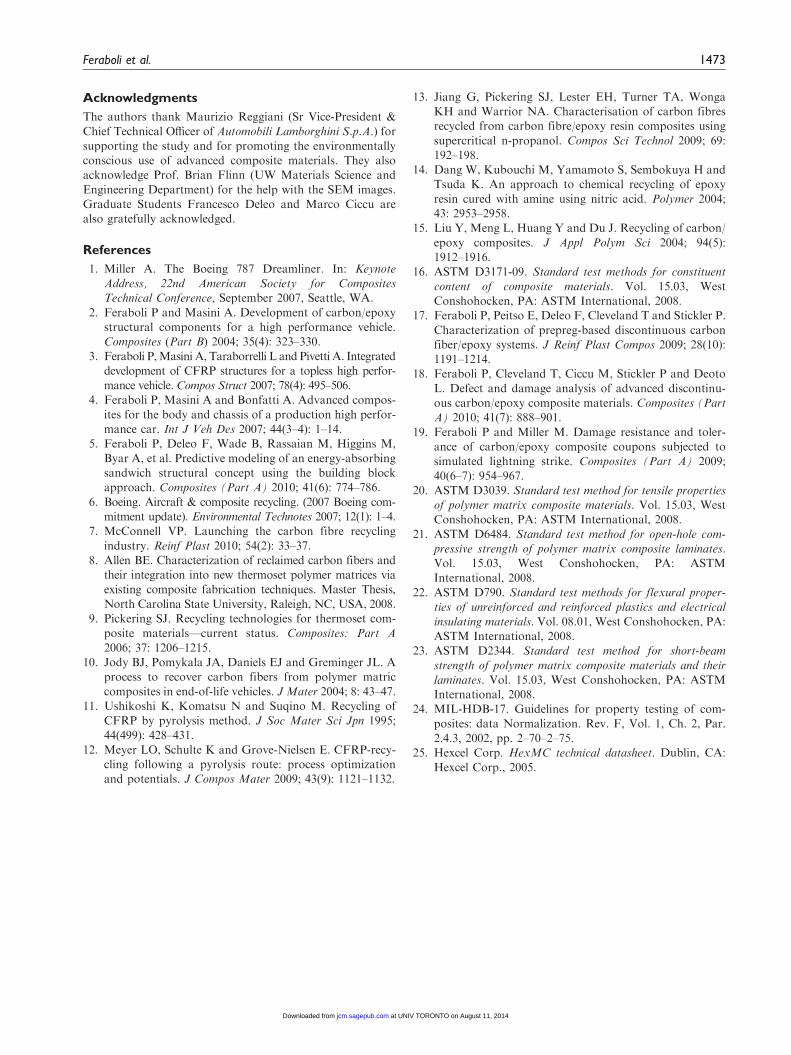
Flexural failure manifests on the tensile side, andpropagates as a shear crack up through the thicknesstoward the compressive side (Figure 15). Three-pointbend flexure strength results for family R are 70%and 52%, respectively, of the flexural strengths of fam-ilies A and B, respectively (Figure 16). The flexurestrength of the stacking sequence with the (0/90) plyon the outer surface is expectedly higher than the onewith the (�45) ply. Normalization cannot be performedfor flexure strength, according to MIL-HDBK-17guidelines,24 but the authors expect that flexurestrength will increase significantly if the fiber volumecontent is increased. It is expected that an average flex-ural strength of approximately 480–500MPa should be
Figure 11. (A) Postfailure image and details of tensile specimen extracted from a vacuum-assisted resin transfer molding (VaRTM)
panel manufactured using the recycled long random fiber reinforcement and (B) surface details showing failure morphology by shearing
and pull-out of tensile specimen.
1470 Journal of Composite Materials 46(12)
at UNIV TORONTO on August 11, 2014jcm.sagepub.comDownloaded from
achieved with a fiber volume content of 50%.Interlaminar shear strength for family R (Figure 17)is 70% of the strength of families A and B. It is typicalof random fiber systems to have short beam shearstrength lower than the continuous fiber system made
of the same fiber and resin system.17,25 This is justifiedby the absence of well-defined interlaminar planes, aswell as the pre-existing kinking of the ‘plies,’ whichleads to premature slipping of the ‘plies’ with respectto each other. Increasing fiber volume content will
Figure 12. Tension strength (A) and modulus (B) results for all
three families. For each family, the light bar represents the as-
measured values, while the dark bar represents a ‘normalized’
value based on a nominal fiber volume content of 50%.
Figure 13. Postfailure image and details of compressive specimen extracted from a vacuum-assisted resin transfer molding (VaRTM)
panel manufactured using the recycled long random fiber reinforcement.
Figure 14. Compression strength (A) and modulus (B) results
for all three families. For each family, the light bar represents the
as-measured values, while the dark bar represents a ‘normalized’
value based on a nominal fiber volume content of 50%.
Feraboli et al. 1471
at UNIV TORONTO on August 11, 2014jcm.sagepub.comDownloaded from
likely not improve the short beam shear strength, but amore homogeneous distribution of the reinforcement(more flat and well-arranged recycled fiber mat) maylead to some improvements.
Conclusions
A recycling process that allows for the separation ofcarbon fibers from the epoxy matrix was demonstrated.The process is based on immersion in boiling sulfuricacid, similar to the ASTM acid digestion standard testmethod. The carbon fibers, which originally featuredtwill architecture, take the appearance of a fuzzy,entangled, random, long-fiber mat following the recy-cling process. VaRTM liquid resin infusion is used tomanufacture panels of both the pristine twill fabric aswell as the recycled fiber mat. The panels manufacturedusing the recycled mat exhibit high thickness variations,and a fiber volume content of 33%, much lower than
the twill at 62%. The preform has lower permeability,and is more difficult to infuse using the VaRTM pro-cess, but the end quality of laminates is good in terms ofvoid content. Both physical properties (ultrasonic andmicrographic images) and mechanical properties (ten-sion, compression, flexure, and short beam shear) of therecycled panels show trends and traits similar to thoseof advanced carbon fiber SMC. However, with furtherdevelopment efforts, it is possible to realign the recycledlong fibers and re-establish their original performance.Furthermore, by optimizing the degree of compac-tion and homogenization of the recycled fiber mat, itwill be possible to increase the fiber volume content tovalues around 45–50%, and dramatically reduce thethickness variation. Finally, though VaRTM is a suit-able process for liquid resin infusion of the preform, apure RTM process will lead to further increases in thequality of the laminate thanks to the higher injectionpressures and control of both inner and outer moldlines.
Figure 15. Postfailure image and details of compressive specimen extracted from a vacuum-assisted resin transfer molding (VaRTM)
panel manufactured using the recycled long random fiber reinforcement.
Figure 16. Measured flexure strength results for all three
families.
Figure 17. Measured short beam shear strength results for all
three families.
1472 Journal of Composite Materials 46(12)
at UNIV TORONTO on August 11, 2014jcm.sagepub.comDownloaded from
Acknowledgments
The authors thank Maurizio Reggiani (Sr Vice-President &
Chief Technical Officer of Automobili Lamborghini S.p.A.) forsupporting the study and for promoting the environmentallyconscious use of advanced composite materials. They alsoacknowledge Prof. Brian Flinn (UW Materials Science and
Engineering Department) for the help with the SEM images.Graduate Students Francesco Deleo and Marco Ciccu arealso gratefully acknowledged.
References
1. Miller A. The Boeing 787 Dreamliner. In: KeynoteAddress, 22nd American Society for CompositesTechnical Conference, September 2007, Seattle, WA.
2. Feraboli P and Masini A. Development of carbon/epoxystructural components for a high performance vehicle.Composites (Part B) 2004; 35(4): 323–330.
3. Feraboli P,Masini A, Taraborrelli L and Pivetti A. Integrateddevelopment of CFRP structures for a topless high perfor-mance vehicle. Compos Struct 2007; 78(4): 495–506.
4. Feraboli P, Masini A and Bonfatti A. Advanced compos-
ites for the body and chassis of a production high perfor-mance car. Int J Veh Des 2007; 44(3–4): 1–14.
5. Feraboli P, Deleo F, Wade B, Rassaian M, Higgins M,
Byar A, et al. Predictive modeling of an energy-absorbingsandwich structural concept using the building blockapproach. Composites (Part A) 2010; 41(6): 774–786.
6. Boeing. Aircraft & composite recycling. (2007 Boeing com-mitment update). Environmental Technotes 2007; 12(1): 1–4.
7. McConnell VP. Launching the carbon fibre recycling
industry. Reinf Plast 2010; 54(2): 33–37.8. Allen BE. Characterization of reclaimed carbon fibers and
their integration into new thermoset polymer matrices viaexisting composite fabrication techniques. Master Thesis,
North Carolina State University, Raleigh, NC, USA, 2008.9. Pickering SJ. Recycling technologies for thermoset com-
posite materials—current status. Composites: Part A
2006; 37: 1206–1215.10. Jody BJ, Pomykala JA, Daniels EJ and Greminger JL. A
process to recover carbon fibers from polymer matric
composites in end-of-life vehicles. J Mater 2004; 8: 43–47.11. Ushikoshi K, Komatsu N and Suqino M. Recycling of
CFRP by pyrolysis method. J Soc Mater Sci Jpn 1995;
44(499): 428–431.12. Meyer LO, Schulte K and Grove-Nielsen E. CFRP-recy-
cling following a pyrolysis route: process optimizationand potentials. J Compos Mater 2009; 43(9): 1121–1132.
13. Jiang G, Pickering SJ, Lester EH, Turner TA, WongaKH and Warrior NA. Characterisation of carbon fibresrecycled from carbon fibre/epoxy resin composites using
supercritical n-propanol. Compos Sci Technol 2009; 69:192–198.
14. Dang W, Kubouchi M, Yamamoto S, Sembokuya H andTsuda K. An approach to chemical recycling of epoxy
resin cured with amine using nitric acid. Polymer 2004;43: 2953–2958.
15. Liu Y, Meng L, Huang Y and Du J. Recycling of carbon/
epoxy composites. J Appl Polym Sci 2004; 94(5):1912–1916.
16. ASTM D3171-09. Standard test methods for constituent
content of composite materials. Vol. 15.03, WestConshohocken, PA: ASTM International, 2008.
17. Feraboli P, Peitso E, Deleo F, Cleveland T and Stickler P.
Characterization of prepreg-based discontinuous carbonfiber/epoxy systems. J Reinf Plast Compos 2009; 28(10):1191–1214.
18. Feraboli P, Cleveland T, Ciccu M, Stickler P and Deoto
L. Defect and damage analysis of advanced discontinu-ous carbon/epoxy composite materials. Composites (PartA) 2010; 41(7): 888–901.
19. Feraboli P and Miller M. Damage resistance and toler-ance of carbon/epoxy composite coupons subjected tosimulated lightning strike. Composites (Part A) 2009;
40(6–7): 954–967.20. ASTM D3039. Standard test method for tensile properties
of polymer matrix composite materials. Vol. 15.03, WestConshohocken, PA: ASTM International, 2008.
21. ASTM D6484. Standard test method for open-hole com-pressive strength of polymer matrix composite laminates.Vol. 15.03, West Conshohocken, PA: ASTM
International, 2008.22. ASTM D790. Standard test methods for flexural proper-
ties of unreinforced and reinforced plastics and electrical
insulating materials. Vol. 08.01, West Conshohocken, PA:ASTM International, 2008.
23. ASTM D2344. Standard test method for short-beam
strength of polymer matrix composite materials and theirlaminates. Vol. 15.03, West Conshohocken, PA: ASTMInternational, 2008.
24. MIL-HDB-17. Guidelines for property testing of com-
posites: data Normalization. Rev. F, Vol. 1, Ch. 2, Par.2.4.3, 2002, pp. 2–70–2–75.
25. Hexcel Corp. HexMC technical datasheet. Dublin, CA:
Hexcel Corp., 2005.
Feraboli et al. 1473
at UNIV TORONTO on August 11, 2014jcm.sagepub.comDownloaded from