Embed Size (px)
Citation preview

Do not use unless all screws are tight. At least every six months, check all screws to be sure they are tight. If parts are missing, broken, damaged, or worn, stop use of the product until repairs are made
by your dealer using factory authorized parts.
Assembly Instructions
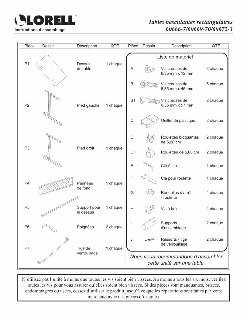
Rectangular Flipper Tables60666-7/60669-70/60672-3
P1A
B
B1
C
D
D1
E
F
G
H
I
J
1 EA8 EA
5 EA
2 EA
2 EA
2 EA
2 EA
1 EA
1 EA
4 EA
4 EA
2 EA
2 EA
Table Top1⁄4" x 12mm Socket Screw
1⁄4" x 45mm Socket Screw
1⁄4" x 57mm Socket Screw
Plastic Grommet
2" Locking Caster
2" Caster
Allen Wrench
Caster Wrench
Lock Washer-Caster
Wood Screws
Connecting Bracket
Spring-Lock Rod
We recommend that you assemble this unit on a table.
Hardware List
Part Drawing Part DrawingQty QtyDescription Description
Left Leg
Right Leg
Modesty Panel
Top Support
Handle
Lock Rod
P2 1 EA
P3 1 EA
P4 1 EA
P5 1 EA
P6 2 EA
P7 1 EA
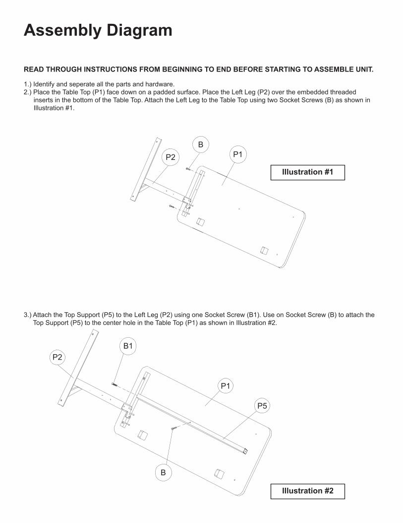
READ THROUGH INSTRUCTIONS FROM BEGINNING TO END BEFORE STARTING TO ASSEMBLE UNIT.
1.) Identify and seperate all the parts and hardware.2.) Place the Table Top (P1) face down on a padded surface. Place the Left Leg (P2) over the embedded threaded inserts in the bottom of the Table Top. Attach the Left Leg to the Table Top using two Socket Screws (B) as shown in Illustration #1.
3.) Attach the Top Support (P5) to the Left Leg (P2) using one Socket Screw (B1). Use on Socket Screw (B) to attach the Top Support (P5) to the center hole in the Table Top (P1) as shown in Illustration #2.
Assembly Diagram
Illustration #1
Illustration #2
P2
P2
P1
P1
P5
B1
B
B

4.) Place the Lock Rod (P7), as shown in Illustration #3, against the Left Leg (P2) and align holes. Insert the Handle (P6) through the outside hole in the Left Leg (P2) and into the hole and the Lock Rod (P7). Align the screw holes and secure with one Socket Screw (A).
5.) Place the Right Leg (P3) over the embedded threaded holes in the bottom of Table Top (P1). Make sure the pinontheinsideoftheRightLegfitsintotheslotoftheLockRod(P7)asitdoesontheLeftLeg(P2). Secure the Right Leg (P3) to the Table Top (P1) using two Socket Screws (B). Attach the Top Support (P5) to the Right Leg using one Socket Screw (B1) as shown in Illustration #4. Insert the Handle (P6) through the Right Leg (P3) and into the Lock Rod and secure with a Socket Screw (A).
Illustration #3
Illustration #4
A
P2
B
A
B1
P6
P3
P1
P7
P6

6.) Attach the Spring (J) to the Left Leg (P2) using one Socket Screw (A) as shown in Illustration #5. Hook the other end of the Spring into the Lock Rod (P7) as shown. Repeat this Step for the Spring (J) to the Right Leg (P3) and Lock Rod (P7).
JP2
D1
P4
D
D
G
A
P7
A
Illustration #5
Illustration #6
7.) Attach the Modesty Panel (P4) between the Right Leg (P3) and the Left Leg (P2) using two Socket Screws (A) into the threaded holes in each leg. Makes sure your Modesty Panel (P4) is positioned as shown in Illustration #6.
8.) Place a Lock Washer (G) on each Caster (D1) and screw into the black holes in the bottom of the Right and Left Legs. Place a Lock Washer (G) on each Caster (D) and screw into the front holes in the bottom of the Right and Left Legs as shown in Illustration #6. Tighten all Casters with Caster Wrench (F).
A

9.) To install Grommets (C), seperate parts and press Grommet Sleeve into each rectangular opening in Top Platform (P1) as shown in Illustration #7.
10.) Snap 2 plastic Caps over top of each Sleeve as shown in Illustration #7.
C
H
I
P1 Sleeve
Cap
Cap
Illustration #7
Illustration #8
11.) Use two Connecting Brackets (I) and four Wood Screws (H) to secure two tables together as shown in Illustration #8.
Cap Cap
Sleeve
Grommet (C)
N’utilisez pas l’unité à moins que toutes les vis soient bien vissées. Au moins à tous les six mois, vérifiez toutes les vis pour vous assurer qu’elles soient bien vissées. Si des pièces sont manquantes, brisées,
endommagées ou usées, cessez d’utiliser le produit jusqu’à ce que les réparations sont faites par votre marchand avec des pièces d’origines.
Instructions d’assemblage
Tables basculantes rectangulaires60666-7/60669-70/60672-3
P1A
B
B1
C
D
D1
E
F
G
H
I
J
1 chaque8 chaque
5 chaque
2 chaque
2 chaque
2 chaque
2 chaque
1 chaque
1 chaque
4 chaque
4 chaque
2 chaque
2 chaque
Dessus de table Vis creuses de
6,35 mm x 12 mm
Vis creuses de 6,35 mm x 45 mm
Vis creuses de 6,35 mm x 57 mm
Oeillet de plastique
Roulettes bloquantes de 5,08 cm
Roulettes de 5,08 cm
Clé Allen
Clé pour roulette
Rondelles d’arrêt - roulette
Vis à bois
Supports d’assemblage
Ressorts - tige de verrouillage
Nous vous recommandons d’assembler cette unité sur une table.
Liste de matériel
Pièce Dessin Pièce DessinQTÉ QTÉDescription Description
Pied gauche
Pied droit
Panneau de fond
Support pour le dessus
Poignées
Tige de verrouillage
P2 1 chaque
P3 1 chaque
P4 1 chaque
P5 1 chaque
P6 2 chaque
P7 1 chaque

VEUILLEz LIRE TOUTES LES INSTRUCTIONS, DU DéBUT à LA FIN, AVANT DE DéBUTER L’ASSEMBLAGE DE L’UNITé.1.)Identifiezetsépareztouteslespiècesetlematériel.2.)Placezledessusdetable(P1)faceverslebassurunesurfacerembourrée.Placezlepiedgauche(P2)au-dessus desinsertsfiletésencastrésquisetrouventsousledessousdudessusdetable.Fixezlepiedgauchesurledessus de table en utilisant deux vis creuses (B) tel qu’illustré dans l’illustration #1.
3.)Fixezlesupportpourledessus(P5)aupiedgauche(P2)enutilisantuneviscreuse(B1).Utilisezunevis creuse(B)pourfixerlesupportpourledessus(P5)autrouducentredansledessusdetable(P1)telqu’illustré dans l’illustration #2.
Schéma d’assemblage
Illustration #1
Illustration #2
P2
P2
P1
P1
P5
B1
B
B

4.)Placezlatigedeverrouillage(P7),telqu’illustrédansl’illustration#3,contrelepiedgauche(P2)etalignez lestrous.Insérezlapoignée(P6)àtraversletrouextérieurdupiedgauche(P2)etdansletroudelatigede verrouillage(P7).Alignezlestrousdevisetsécurisezavecunevisecreuse(A).
5.)Placezlepieddroit(P3)au-dessusdestrousfiletésencastrésquisetrouventsousledessousdudessus detable(P1).Assurez-vousquelabrocheàl’intérieurdupieddroits’insèredanslafentedelatigede verrouillage(P7)commeellelefaitdanslepiedgauche(P2).Sécurisezlepieddroit(P3)audessusde table(P1)avecdeuxviscreuses(B).Fixezlesupportpourledessus(P5)aupieddroitenutilisantunevis creuse(B1)telqu’illustrédansl’illustration#4.Insérezlapoignée(P6)àtraverslepieddroit(P3)etdansla tigedeverrouillage,puissécurisezavecuneviscreuse(A).
Illustration #3
Illustration #4
A
P2
B
A
B1
P6
P3
P1
P7
P6

6.)Fixezleressort(J)aupiedgauche(P2)enutilisantuneviscreuse(A)telqu’illustrédansl’illustration#5.Accrochez l’autreextrémitéduressortdanslatigedeverrouillage(P7)telqu’illustré.Répétezcetteétapepourleressort(J)au pied droit (P3) et à la tige de verrouillage (P7).
JP2
D1
P4
D
D
G
A
P7
A
Illustration #5
Illustration #6
7.)Fixezlepanneaudefond(P4)entrelepieddroit(P3)etlepiedgauche(P2)enutilisantdeuxviscreuses(A)dansles trousfiletésdechaquepied.Assurez-vousquevotrepanneaudefond(P4)soitpositionnételqu’illustrédans l’illustration #6.
8.)Placezunerondelled’arrêt(G)surchaqueroulette(D1)etvissez-lesdanslestrousenarrièreaudessousdupied droitetgauche.Placezunerondelled’arrêt(G)surchaqueroulette(D)etvissez-lesdanslestrousenavantau dessousdupieddroitetgauchetelqu’illustrédansl’illustration#6.Serreztouteslesroulettesaveclaclépour roulette (F).
A

9.)Pourinstallerl’œillet(C),séparezlespiècesetappuyezlemanchondel’œilletdanschaqueouverturerectangulaire dans la plate-forme du dessus (P1) tel qu’illustré dans l’illustration #7.
10)Enclenchez2capuchonsdeplastiqueau-dessusdumanchontelqu’illustrédansl’illustration#7.
C
H
I
P1 Manchon
Capuchon
Capuchon
Illustration #7
Illustration #8
11.)Utilisezdeuxsupportsd’assemblage(I)etquatrevisàbois(H)poursécuriserdeuxtablesensembletelqu’illustré dans l’illustration #8.
Capuchon Capuchon
Manchon
Oeillets (C)

No use la unidad a menso que todos los tornillos estén apretados. Revise todos los tornillos por lo menos cada seis meses para asegurarse que estén apretados. Si faltan piezas o están dañadas o desgastadas, deje
de usar el producto hasta que el vendedor o usted hagan las reparaciones usando las piezas de fábrica.
Instrucciones de armado
Mesas rectangulares de soporte60666-7/60669-70/60672-3
P1A
B
B1
C
D
D1
E
F
G
H
I
J
1 CU8 CU
5 CU
2 CU
2 CU
2 CU
2 CU
1 CU
1 CU
4 CU
4 CU
2 CU
2 CU
CubiertaTornillosdecabeza hueca 6,35 mm x 12mm
Tornillosdecabeza hueca 6,35 mm x 45mm
Tornillosdecabeza hueca 6,35 mm x 57mm
Pasacables de plástico
Ruedas con bloqueador 5,08 cm
Ruedas giratoria de 5,08 cm
Llave Allen
Llave para las ruedas
Arandelas de seguridad
Tornillos para madera
Soporte de conexión
Gancho resorte de varilla
Le recomendamos que arme esta unidad sobre una mesa.
Lista de Accesorios
Parte Dibujo Parte DibujoCant CantDescripción Descripción
Pata izquierda
Pata derecha
Tapapiernas
Soporte superior
Asa
Varilla de seguridad
P2 1 CU
P3 1 CU
P4 1 CU
P5 1 CU
P6 2 CU
P7 1 CU

LEA LAS INSTRUCCIONES COMpLETAMNTE DE pRINCIpIO A FIN ANTES DE EMpEzAR A ARMAR LA UNIDAD.1.)Identifiqueyseparetodaslaspiezasylosaccesorios.2.)Coloquelacubierta(P1)bocaabajoenunasuperficieacolchada.Pongalapataizquierda(P2)sobrelosinsertos roscadosqueseencuentranenlapartedeabajodelacubierta.Fijelapataizquierdaalacubiertausandodos tornillosdecabezahueca(B)comosemuestraenelDibujo#1.
3.)Fijeelsoportesuperior(P5)alapataizquierda(P2)usandountornillodecabezahueca(B1).Useuntornillode cabezahueca(B)parafijarelsoportesuperior(P5)alagujerocentraldelacubiertadelamesa(P1)segúnse muestra en el Dibujo #2.
Diagrama de armado
Dibujo #1
Dibujo #2
P2
P2
P1
P1
P5
B1
B
B

4.)Coloquelavarilladeseguridad(P7),comosemuestraenelDibujo#3,contralapataizquierda(P2)y alineelosagujeros.Inserteelasa(P6)atravésdelagujeroexteriorenlapataizquierda(P2)yenelagujero delavarilladeseguridad(P7)Alineelasperforacionesdetornilloyasegureconuntornillodecabeza hueca (A).
5.) Ponga la pata derecha (P3) sobre los insertos roscados que se encuentran en la parte de abajo de la cubierta(P1).Asegúresequeelbrochequeseencuentradentrodelapataderechaseajusteenlaranura delavarilladeseguridad(P7)igualquelapataizquierda(P2).Asegurelapataderecha(P3)enlacubierta delamesa(P1)usandountornillodecabezahueca(B).Fijeelsoportesuperior(P5)lapataderecha usandountornillodecabezahueca(B1)comosemuestraenelDibujo#4.Inserteelasa(P6)atarvésde lapataderecha(P3)yenlavarilladeseguridadyasegureconuntornillodecabezahueca(A).
Dibujo #3
Dibujo #4
A
P2
B
A
B1
P6
P3
P1
P7
P6

6.)Fijeelresorte(J)alapataizquierda(P2)usandountornillodecabezahueca(A)comosemuestraenelDibujo#5. Ganche el otro extremo del resorte en la varilla de seguridad (P7) como se muestra. Repita este paso para el resorte (J) a la pata derecha (P3) y la varilla de seguridad (P7).
JP2
D1
P4
D
D
G
A
P7
A
Dibujo #5
Dibujo #6
7.)Fijeelcubrepiernas(P4)entrelapataderecha(P3)ylapataizquierda(P2)usandodostornillosdecabezahueca(A) enlosagujerosrosadosdecadapata.Asegúresequeelcubrepiernas(P4)seencuentrecolocadocomosemuestra en el Dibujo #6.
8.) Coloque una arandela (G) en cada rueda (D1) y atornille en los agujeros que se encuentran en la parte inferior de las patasderechaeizquierda.Coloqueunaarandela(G)encadarueda(D)yatornilleenlosagujerosdelfrenteenla parteposteriordelaspatasderechaeizquierdacomosemuestraenelDibujo#6.Aprietetodaslasruedasconla llave (F).
A

9.)Parainstalarelpasacables(C),separelaspiezasyoprimalamangadelpasacablesencadaaperturarectangularde la plataforma superior (P1) como se muestra en el Dibujo #7.
10) Chasquee 2 cubiertas de plástico sobre la parte superior de la manga como se muestra en el Dibujo #7.
C
H
I
P1 Manga
Cubierta
Cubierta
Dibujo #7
Dibujo #8
11.) Use dos soportes de conexión (I) y cuatro tornillos para madera (H) para asegurar dos mesas juntas como se muestra en el Dibujo #8.
Cubierta Cubierta
Manga
Pasacables (C)
Instructions
Call Us First! DO NOT RETURN TO STORE. For immediate help with assembly or product information call our toll-free number: 1-888-598-7316 Mon. - Fri. 7am to 7 pm CST Our staff is ready to provide assistance. Damaged or missing parts ship from our facility in 1-2 business days.
Please provide the following information:1. Full Name2. Physical Address – do not include P.O. Box as our carriers cannot deliver to P.O. Boxes3. Phone Number4. Model Number5. Part Number6. Invoice #7. Date of PurchaseNote: Our policy is to send all parts requests via normal ground transportation. If your requirements are to have these parts via overnight/next day, please provide your designated carrier and account number. Replacement panels are not available. If any damage has occurred during shipment please return the entire unit to place of purchase for credit and replacement. Original invoice may be required.
Before you begin:Open, identify and count all parts prior to assembly. Lay out the parts on a non-abrasive surface such as carpet or blanket.
Instructions
appelez-noUs d’abord! NE REVENEZ PAS AU MAGASIN. Pour obtenir une aide immédiate concernant l’assemblage ou des informations sur les produits, appelez notre numéro sans frais : 1-888-598-7316 Lun. - vend. 7h à 19 h CST Notre personnel vous attend pour vous offrir son aide. Les pièces endommagées ou manquantes sont expédiées de nos locaux sous 1 à 2 jours ouvrables.
Veuillez inclure les informations suivantes :1. Nom complet2. Adresse physique – ne pas inclure de boîte postale, car nos porteurs ne peuvent pas livrer à ces boîtes.3. Numéro de téléphone4. Numéro de modèle5. Numéro de pièce6. Numéro de facture7. Date d’achatRemarque : Notre politique est d’envoyer toutes les pièces demandées par transport terrestre normal. Si vous voulez recevoir ces pièces le jour suivant, indiquez votre porteur désigné ainsi qu’un numéro de compte. Nous ne fournissons pas de panneaux de rechange. En cas d’endommagement en cours de transport, renvoyez l’unité entière au lieu d’achat pour recevoir un crédit ou un échange. La facture originale vous sera peut-être demandée.
Avant de commencer:Ouvrez, identifiez et comptez toutes les pièces avant l’assemblage. Disposez à plat les pièces sur une surface non abrasive comme un tapis ou une couverture.
Instrucciones
¡llámenos primero! NO DEVUELVA EL PRODUCTO A LA TIENDA. Para recibir ayuda inmediata con el ensamble o información del producto, llame a nuestro número gratuito: 1-888-598-7316 De lunes a viernes de 7 a.m. a 7 p.m., hora del Centro. Nuestro personal está preparado para brindarle asistencia. Las partes dañadas o faltantes saldrán de nuestras instalaciones en el transcurso de 1 a 2 días hábiles.
Recuerde proporcionar la siguiente información:1. Nombre completo2. Domicilio físico – No incluya apartados postales debido a que no podemos realizar entregas en un apartado postal.3. Número telefónico4. Número de modelo5. Número de parte6. Número de factura7. Fecha de compra
Nota: Nuestra política es enviar todas las solicitudes de partes por transporte terrestre regular. Si usted solicitó el envío de estas partes durante la noche o con entrega al día siguiente, proporcione el nombre de su compañía de mensajería y su número de cuenta. Los paneles de repuesto no están disponibles. Si ocurrió algún daño durante el envío, devuelva la unidad completa al lugar de compra para su devolución o reposición. Es posible que le pidan la factura original.
Antes de iniciar:Abra, identifique y cuente todas las partes antes del ensamble. Coloque todas las partes en una superficie no abrasiva, como una alfombra o sábana.