Embed Size (px)
Citation preview
1
Rectangular Filament-Wound GFRP Tubes Filled with Concrete under Flexural
and Axial Loading: Experimental Investigation
Amir Fam 1, David Schnerch 2 and Sami Rizkalla 3
ABSTRACT
This paper presents results of an experimental investigation using full scale concrete-filled
rectangular filament-wound glass fibre reinforced polymer (GFRP) tubes (CFRFT). The tubes
include fibres oriented at ±45 and 90 degrees with respect to the longitudinal axis. Additional
longitudinal fibres [0 degree] are provided in the flanges only for flexural rigidity. Three beam
tests and five short column tests with concentric and eccentric axial loading were conducted. In
beam tests, totally filled tubes and a tube partially filled with concrete using a central hole for
reducing deadweight were tested. The effect of reinforcement ratio is examined by testing beams
with GFRP tubes of two different sizes. The behaviour of CFRFT is compared to conventional
concrete-filled rectangular steel tubes (CFRST) of similar reinforcement ratios. The short
columns were tested under eccentricity ratios (e/h) of 0, 0.092, 0.184 and 0.236, where h is the
depth of the cross-section. Transverse strains were measured around the perimeter of the
concentrically loaded column to evaluate confinement effectiveness of CFRFT. The study
showed that CFRFT is a practical and feasible system that offers similar flexural strength to
CFRST of similar reinforcement ratio. Unlike circular concrete-filled FRP tubes, bulging of
CFRFT columns reduces their confinement effectiveness.
Keywords: FRP, filament wound, rectangular tube, beam, column, concrete-filled, confinement
______________________________________________________________________________ 1 Assistant Professor and Canada Research Chair in Innovative and Retrofitted Structures, Dept. of Civil Eng., Queen’s University, Kingston, ON K7L 3N6 2 Doctoral Student, Civil Eng. Dept., North Carolina State University, Raleigh, NC 27695-7533 3 Distinguished Professor of Civil Engineering and Construction, Director of the Constructed Facilities Laboratory, Civil Engineering Department, North Carolina State University, Raleigh, NC 27695-7533
2
INTRODUCTION
The use of fibre-reinforced polymers (FRP) as structurally integrated stay-in-place formwork for
concrete structures maximizes the advantages of both FRP and concrete, while simplifying the
construction procedure, particularly when using closed tubular sections. In this case, circular or
rectangular FRP tubes are filled with concrete and used as axial or flexural members. The tube
provides lightweight permanent formwork and non-corrosive reinforcement simultaneously.
Concrete-filled rectangular and circular steel tubes have been extensively studied in bending and
under axial loads [Tomii and Sakino (1979), Lu and Kennedy (1992), and Kilpatrick and Rangan
(1997), among several other researchers].
A number of FRP-concrete hybrid systems have been developed over the years, including
both open and closed FRP forms. While concrete-filled circular FRP tubes have been extensively
studied in bending and under axial loads [Burgeno et al (1998), Mirmiran et al (2000), Fam and
Rizkalla 2001(a) and Fam et al (2003b)], very limited studies have been conducted on
rectangular, open or closed, FRP-concrete hybrid systems. Fardis and Khalili (1981) proposed a
rectangular FRP box section with one side open and filled with concrete for beam applications.
The beams failed by crushing of concrete, followed by bursting of FRP in compression.
Triantafillou and Meier (1992) proposed a beam system consisting of rectangular glass-FRP
(GFRP) box section with a carbon-FRP (CFRP) laminate bonded to the GFRP tension flange and
a concrete layer cast on top of the compression GFRP flange. The system provides pseudo-
ductility, where the CFRP layer fractures first, followed by a load drop and lowered stiffness,
and eventually, the concrete crushes or debonds from GFRP. Hall and Mottram (1998) presented
a hybrid section combining GFRP pultruded sections having two T-up-stands and a continuous
base, commercially available as floor panels, with concrete. The beams failed by shear in
3
concrete due to the lack of shear reinforcement. Mirmiran et al (1999) tested five square
concrete-filled GFRP tubes under various combinations of axial and transverse loads to develop
a moment-thrust interaction diagram. In the compression control region, the columns proved as
strong as equivalent conventional reinforced concrete columns with six percent reinforcement.
In this paper, rectangular filament-wound GFRP tubes, totally and partially filled with
concrete, were tested. The tubes contain fibers oriented at various directions, including [±45]
and [90] degrees for shear resistance and possible confinement. Additional unidirectional layers
are provided only in the upper and lower flanges for flexural rigidity. The system is tested in
bending as well as under concentric and eccentric axial compression. The study is focused on
evaluating the effects of the inner void provided in beams to reduce the dead weight, the effect of
reinforcement ratio in terms of the ratio of cross-sectional areas of GFRP and concrete,
comparison with conventional concrete-filled steel tubes and examining the progressive failure
behavior of GFRP laminate resulting from the various orientations of the layers, which could
result in a non-linear behavior of GFRP tubes. In a companion paper [Fam et al (2003a)]; an
analytical model is introduced to predict the behavior of this system under different
combinations of bending and axial loading, accounting for the progressive laminate failure
effect. The model is used in a parametric study to investigate a wider range of parameters beyond
the limitation of the experimental program and to compare the behavior of CFRFT to that of
conventional reinforced concrete (RC) sections.
EXPERIMENTAL PROGRAM
The experimental program includes three full scale beam tests and five column tests conducted
on concentrically and eccentrically axially loaded specimens. The specimens consisted of
4
concrete-filled rectangular GFRP tubes (CFRFT) of two different sizes. The objective of the
experimental program is to study the flexural behaviour of rectangular CFRFT specimens as well
as to establish the axial load – bending moment interaction curve of CFRFT. The confinement
effectiveness of rectangular tubes is evaluated. The study is also aimed at optimizing the beam
section by providing a central hole to reduce the self-weight of the beam. In this case, the
concrete was cast with a void offset towards the tension side of the tube such that the concrete is
optimally used for compression, shear and stability of the FRP tube.
• GFRP Rectangular Tubes
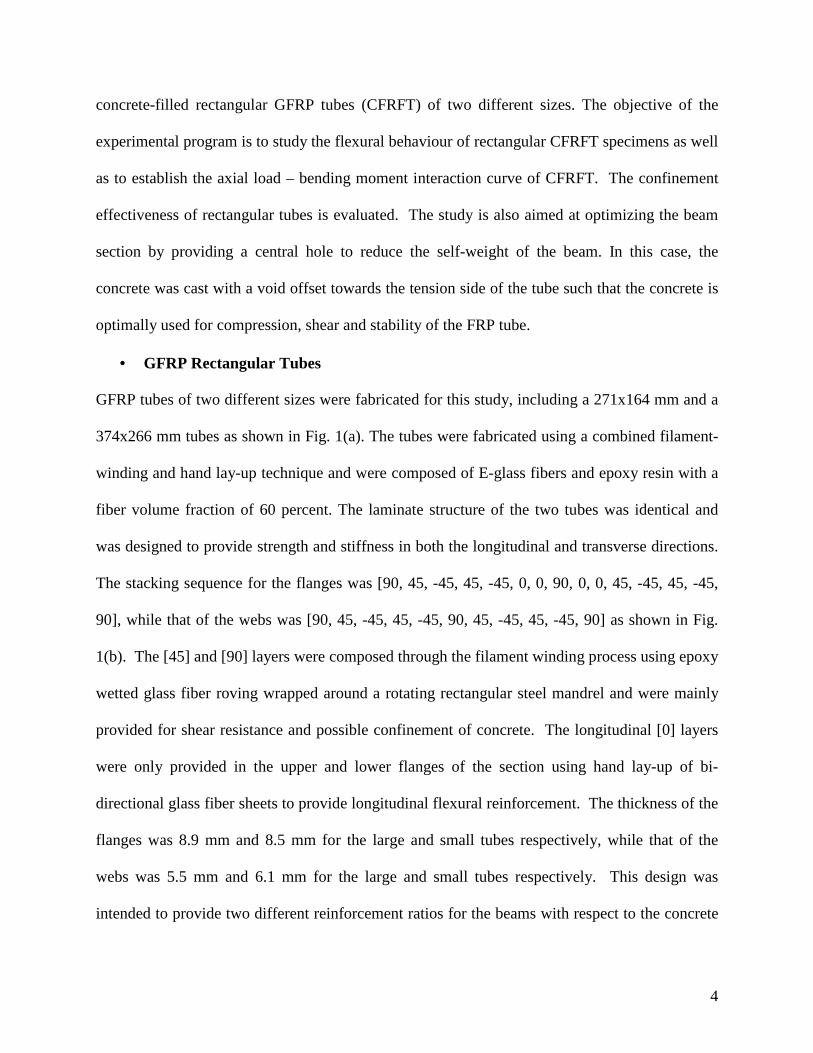
GFRP tubes of two different sizes were fabricated for this study, including a 271x164 mm and a
374x266 mm tubes as shown in Fig. 1(a). The tubes were fabricated using a combined filament-
winding and hand lay-up technique and were composed of E-glass fibers and epoxy resin with a
fiber volume fraction of 60 percent. The laminate structure of the two tubes was identical and
was designed to provide strength and stiffness in both the longitudinal and transverse directions.
The stacking sequence for the flanges was [90, 45, -45, 45, -45, 0, 0, 90, 0, 0, 45, -45, 45, -45,
90], while that of the webs was [90, 45, -45, 45, -45, 90, 45, -45, 45, -45, 90] as shown in Fig.
1(b). The [45] and [90] layers were composed through the filament winding process using epoxy
wetted glass fiber roving wrapped around a rotating rectangular steel mandrel and were mainly
provided for shear resistance and possible confinement of concrete. The longitudinal [0] layers
were only provided in the upper and lower flanges of the section using hand lay-up of bi-
directional glass fiber sheets to provide longitudinal flexural reinforcement. The thickness of the
flanges was 8.9 mm and 8.5 mm for the large and small tubes respectively, while that of the
webs was 5.5 mm and 6.1 mm for the large and small tubes respectively. This design was
intended to provide two different reinforcement ratios for the beams with respect to the concrete
5
cross-sectional areas. The tubes had round corners with a 15 mm radius to avoid damage of the
glass fibers at the corner due to stress concentration. After curing of the filament-wound
assembly, the steel mandrel was removed from the core. In order to enhance the bond between
the concrete core and the tube, the inner surface was coated with a layer of epoxy resin. Coarse
silica sand was then applied over the surface as shown in Fig. 1(c) to produce a rough texture.
• Beam Specimens
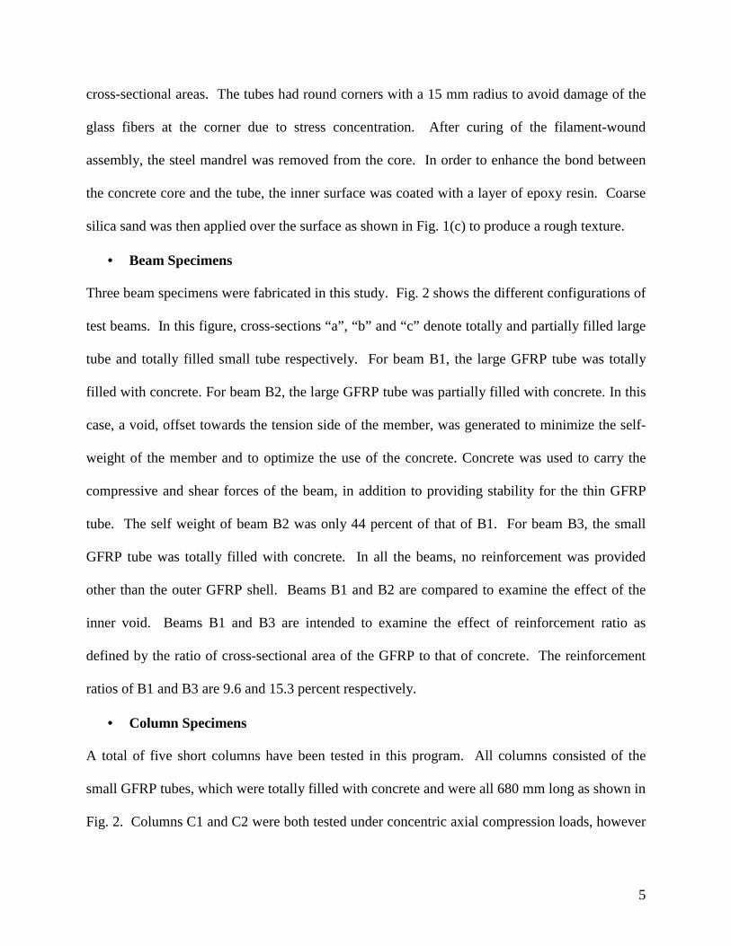
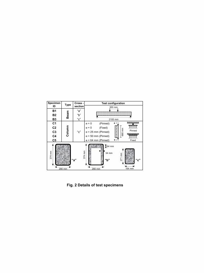
Three beam specimens were fabricated in this study. Fig. 2 shows the different configurations of
test beams. In this figure, cross-sections “a”, “b” and “c” denote totally and partially filled large
tube and totally filled small tube respectively. For beam B1, the large GFRP tube was totally
filled with concrete. For beam B2, the large GFRP tube was partially filled with concrete. In this
case, a void, offset towards the tension side of the member, was generated to minimize the self-
weight of the member and to optimize the use of the concrete. Concrete was used to carry the
compressive and shear forces of the beam, in addition to providing stability for the thin GFRP
tube. The self weight of beam B2 was only 44 percent of that of B1. For beam B3, the small
GFRP tube was totally filled with concrete. In all the beams, no reinforcement was provided
other than the outer GFRP shell. Beams B1 and B2 are compared to examine the effect of the
inner void. Beams B1 and B3 are intended to examine the effect of reinforcement ratio as
defined by the ratio of cross-sectional area of the GFRP to that of concrete. The reinforcement
ratios of B1 and B3 are 9.6 and 15.3 percent respectively.
• Column Specimens
A total of five short columns have been tested in this program. All columns consisted of the
small GFRP tubes, which were totally filled with concrete and were all 680 mm long as shown in
Fig. 2. Columns C1 and C2 were both tested under concentric axial compression loads, however
6
C1 was loaded through a pinned end connections, while C2 had fixed ends. Columns C3, C4 and
C5 were tested under eccentric loads at eccentricities of 25 mm, 50 mm and 64 mm respectively.
C1 and C2 are intended to compare the effect of end loading conditions. The test columns, along
with beam B3 are used to provide various points on the interaction diagram of CFRFT, using the
small GFRP tube.
• Fabrication of Test Specimens
The small and large GFRP tubes were supported and braced in a vertical position as shown in
Fig. 3. Wooden end caps were provided at the bottom. Concrete was cast from the top end into
the tubes, where the tubes themselves provided the formwork. For the partially filled tube, beam
B2, which has a void inside the concrete core, a Styrofoam prism of the same size as the inner
void was fabricated and inserted inside the tube before casting. Vibration of the concrete was
applied during the gradual filling of the tubes. Later, after hardening of the concrete, the
Styrofoam core was removed as shown in the cross-section of beam B2 given in Fig. 3. In order
to prevent crippling of the thin webs of beam B2 above the supports, concrete end blocks were
cast, filling in the void over a length of 375 mm from each end. The column specimens were cut
from the totally filled small tubes to the desired length, using a diamond blade saw.
• Material Testing of GFRP Tube
Both tension and compression tests were conducted on coupons cut from the flange and web of
the large tubes, in the longitudinal direction, using a water-cooled diamond blade saw. For
tension tests, ten 305x38 mm coupons were cut from the flange and web (five from each). The
tests were conducted according to ASTM D3039, where aluminum tabs were used to grip the
coupon at both ends in the testing machine such that the clear distance between the tabs was 65
mm, as shown in Fig. 4(a) and (c). The axial strains were measured using strain gauges. For the
7
compression tests, seven 29x38 mm coupons were cut from the web and the flange of the large
tubes as shown in Fig. 4(b). The loading surfaces were then sanded smooth and parallel using a
special jig. The coupons were then tested in compression as shown in Fig. 4(d), where the axial
displacement was measured by displacement transducer.
• Material Testing of Concrete
Concrete strength was determined by cutting concrete prisms from a portion of the large beam
near to one of the supports. The prisms were cut to a size of 152 mm on all sides using a water-
cooled concrete saw, and the two loaded ends were ground smooth and parallel to eliminate the
need for sulphur capping. Using the relationship proposed by L’Hermite [Neville 1968], the
equivalent concrete cylinder strength based on the prism tests was found to be 52 MPa.
• Test Setup and Instrumentation of Beam Specimens
The three beam specimens were tested using four-point bending as shown in Fig. 5(a). The span
of the beams was 2100 mm and the distance between the loads was 300 mm as shown in Fig. 2.
The beams were loaded using displacement control with a 2000 kN capacity hydraulic actuator
using displacement rate of 0.50 mm/min. The specimens were instrumented to record load,
deflection and strain measurements. Longitudinal strains at mid-span were measured using
strain gauge type displacement transducers and electrical foil gauges attached directly to the
GFRP surface at the extreme tension and compression faces of the beams. Additional gages were
used to measure the axial strains at different levels along the depth of beam B3. Transverse
strains were also measured in the compression zone using foil strain gages attached to the GFRP
tubes of beams B1 and B2. Two displacement potentiometers were used to measure the mid-span
deflection and another one was used to measure any settlement of support. Digital displacement
gauges and potentiometers were also used to measure the slip between the concrete core and the
8
GFRP tube. The slip measurements were taken on both the tension and compression sides, at
both ends of beams B1and B2 and only at the tension side of B3.
• Test Setup and Instrumentation of Short Column Specimens
Compression specimens were subjected to concentric and eccentric axial loads applied at various
eccentricities using a 9000 kN capacity testing machine as shown in Fig. 5(b). Columns C1, C3,
C4 and C5 were tested using a setup with free rotation allowed at the ends as shown in Fig. 5(c).
Specimen C2 was tested between fixed platens, without allowing end rotation. A thin layer of
gypsum plaster was used to distribute the load from the steel plates to the specimens. Specimens
were loaded under stroke control at a displacement rate of 0.165 mm/min. Axial load and strain
measurements were taken for the compression specimens. Strain was measured in the axial
direction at opposite faces using electrical foil gauges and strain gauge type displacement
transducers with a gauge length of 200 mm. Foil strain gauges were also used in the transverse
direction to measure the transverse strains. In C1 specimen, one quarter of the perimeter was
heavily instrumented with foil strain gages in the transverse direction at mid-height to evaluate
the confinement effectiveness.
EXPERIMENTAL RESULTS
In the following sections, the beam and column test results as well as the results of the tension
and compression coupon tests are presented. The different failure modes of the specimens are
also presented and discussed.
• GFRP Coupon Test Results
The stress-strain curves of the tension coupons for both the flange and the web of the GFRP tube
are shown in Fig. 6(a). The figure clearly shows that the tensile strength and stiffness of the
9
flange are significantly higher than the web due to the presence of additional four longitudinal
[0] GFRP layers. The tensile strengths are 316 MPa and 152 MPa for the flange and web
respectively. The stress-strain curves reflect the progressive failure of the different layers, which
was initiated by failure of the transverse [90] layers, followed by failure of the [45] layers, which
corresponds to the ultimate strength of the web. However, in the flange, ultimate strength was
reached when the longitudinal [0] layers ruptured later at a significantly higher load than that
corresponding to failure of the [45] layers. Fig. 6(a) also shows a typical tension specimen after
failure. Fig. 6(b) shows the stress-strain curves of the compression coupons for both the flange
and web. The compressive strengths were 260 MPa and 187 MPa for the flange and web
respectively. The figure also shows the specimen after failure, which occurred due to
combination of crushing and splitting.
The presence of additional four longitudinal [0] layers, which compose 26 percent
reinforcement ratio within the flange, have resulted in increasing the tensile strength of the
flange by 108 percent, while the compressive strength has increased by only 39 percent
compared to the web. It can also be seen that the absence of longitudinal [0] layers, result in a
rather non-linear behaviour as the contribution of the resin matrix, which is a nonlinear material,
becomes more pronounced.
• Beam Test Results
The load-mid span deflection behaviour of the three test beams is shown in Fig. 7. In general,
the behaviour is slightly non-linear as a result of the relatively non-linear stress-strain curves of
the GFRP tubes, shown in Fig. 6, as well as the non-linear characteristics of the concrete fill.
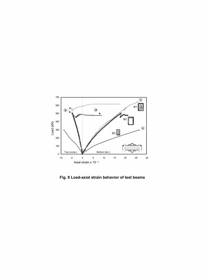
The cracking load is relatively low compared to the ultimate load. The load-axial strain
behaviour of the beams is shown in Fig. 8, in terms of the top fibre compressive strains as well as
10
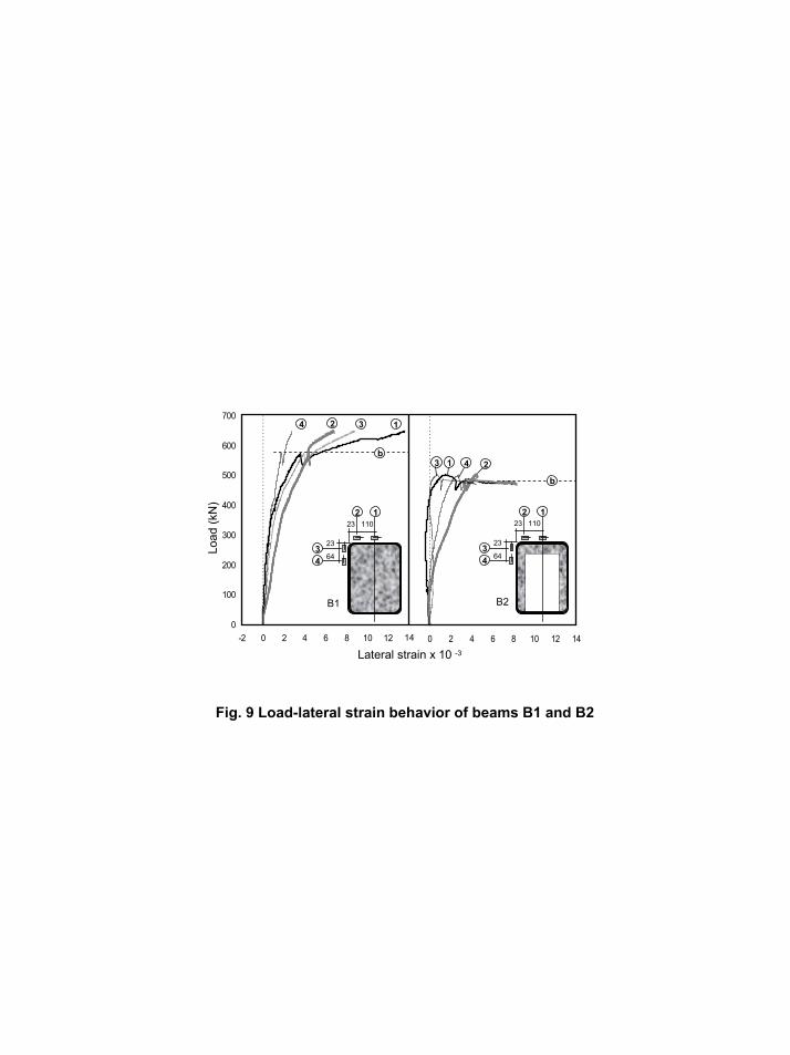
the bottom fibre tensile strains. The load-transverse strain behaviour in the compression side of
the beams is shown in Fig. 9, for B1 and B2. The variation of the neutral axis depth with the
load is given in Fig. 10. The load-slip behaviour as measured at the ends of the beams between
the concrete core and the GFRP tube is given in Fig. 11. The normalized moment-curvature
response of beams B1, B2 and B3 as well as additional concrete-filled rectangular steel tubes
selected from the literature is compared in Fig. 12. The failure modes of the beams are shown in
Fig. 13. In the following sections, the flexural behaviour of CFRFT is discussed in details.
Effect of inner void:
The effect of inner void is studied by comparing beams B1 and B2. The load-deflection
behaviour as well as the load-axial strain behaviour of beams B1 (totally filled) and B2 (with
void) is given in Fig. 7 and Fig. 8, respectively, and shows that both beams had identical flexural
stiffness, which indicates that the “cracked” moment of inertia of B2 is similar to that of B1.
However, the cracking load of B1, point “a”, is higher than B2 due to the higher “uncracked”
moment of inertia of B1. The flexural strength of B2, point “b”, is about 22 percent lower than
B1, point “c”. This is attributed to the different failure modes of the two beams, where B1 failed
in tension while B2 failed in compression as shown in Fig. 13. In B1, the GFRP bottom flange
ruptured at an axial strain of 0.026, which is the ultimate tensile strain of the flange as confirmed
by the coupon tension test results shown in Fig. 6(a). The corresponding maximum axial
compressive strain at the compression side of B1 at failure was 0.005, point “b”, which is only
25 percent of the ultimate compressive strain of the GFRP flange based on coupon test results
shown in Fig. 6(b). At point “b”, in Fig. 7 and Fig. 8, the GFRP compression flange of B1
showed signs of outward local buckling and separation from concrete. This was reflected by a
drop in the load and a reversed direction of the axial compressive strain. However, the beam
11
continued to carry additional load up to point “c”, where tension failure occurred as shown in
Fig. 13. B2 also suffered outward local buckling of the GFRP compression flange, point “b”, at
an axial strain of about 0.005, however, the load never recovered as the flange buckling was
accompanied by cracking and inward buckling of the relatively thin concrete flange inside the
tube as shown in Fig. 13, and marked as point “d” in Fig. 7 and Fig. 8. Buckling of GFRP resulted
in debonding from the concrete and not only reduced the effectiveness of the compression flange in
carrying the compression force, but also eliminated any partial confinement effect of concrete. The axial
tensile strain at the bottom GFRP flange at failure was only 0.021. Although the flexural
strength of B2 is 22 percent lower than that of B1, the dead weight of B1 is 56 percent lighter
than B2, resulting in an over all strength-to-weight ratio for B2, 77 percent higher than B1.
Fig. 9 shows the load-transverse strain behaviour of B1 and B2 in the compression zone.
It should be noted that initially, the transverse tensile strains are a result of the Poisson’s ratio
effect of the tube under longitudinal compressive strains. As the load increases to level “b”, local
buckling of the GFRP flange occurs and induces lateral local bending in the flange, subjecting its
upper surface to additional tensile strains. This is most pronounced at the centre line of the
flange of B1 as indicated by the lateral strains at station number 1. In B1, the round corners of
the GFRP tube provide partial confinement of concrete in compression. This is indicated by the
higher levels of lateral strains at stations 2 and 3 compared to station 1, up to level “b”, before
local buckling occurred.
The variation of the neutral axis depth with the load in B1 and B2 is shown in Fig. 10.
Once cracking occurs in both beams, the neutral axis level becomes more or less stable at a depth
of 20 to 30 percent of the total depth of the section. This indicates that the concrete compression
flange of B2 was optimally used.
12
Relative displacement between the concrete core and the GFRP tube was recorded during
testing. Fig. 11 shows the load-slip behaviour of B1 for both ends, including tension and
compression sides. The slip indicates outward movement of the concrete core relative to the
GFRP tube. Slip started to occur rapidly between 350 and 450 kN. At ultimate, the slip values
were 1.5 to 2 mm. For B2 the amount of slip was negligible compared to B1, where the
maximum measured slip was less than 0.01 mm throughout the duration of loading. This is
attributed to the initiation of inwards buckling and cracking of the thin concrete compression
flange, which resulted in discontinuity between the concrete segments on the right and left of the
centreline of the beam, essentially relieving the concrete core from stresses. At this stage, the
GFRP shell was carrying most of the internal forces and no slip occurred.
Although none of the beams failed in shear, the contribution of the GFRP tube in
resisting shear, Vf, can be approximately evaluated from the measured values reduced by the
concrete contribution in shear, Vc, which is calculated according to ACI 318-99 as dbf wc'17.0 .
In this case, dbw is approximated as the area of the concrete web. For B1 and B2, Vc is
calculated as 112 kN and 30 kN respectively. Knowing the shear force at ultimate flexural
failure for B1 and B2, it can be concluded that the GFRP tubes have approximately contributed
211 kN and 221 kN in B1 and B2 respectively. Assuming an angle of 45 degrees for the
diagonal crack, these forces correspond to tensile stress level in the GFRP webs of 51 MPa and
54 MPa for B1 and B2 respectively, which are relatively low stresses.
Effect of reinforcement ratio:
The effect of reinforcement ratio is studied by comparing beams B1 and B3. In both beams, the
laminate structure and thicknesses of the flange and web are similar; however, the size of the
beams is different, which results in two different reinforcement ratios of 9.6 and 15.3 percent for
13
B1 and B3 respectively. The reinforcement ratio ρ is defined as the ratio of cross-sectional area
of FRP tube to that of concrete. The load-deflection and load-axial strain behaviour of the two
beams are shown in Figures 7 and 8. Similar to B1, B3 had flexural tension failure by rupture of
the GFRP tube as shown in Fig. 13. Failure occurred at axial tensile strain of about 0.027, similar
to B1. However, the corresponding axial compression strain in the upper flange was 0.0088,
which is 80 percent higher than B1. It should be noted that B3 did not suffer from local buckling
of the GFRP compression flange as evident by the compressive strain behaviour, compared to
B1. The width-to-thickness (b/t) ratio of the GFRP flanges of B1 and B3 were 30 and 19
respectively, therefore, B3 was less susceptible to local buckling.
Fig. 12 shows the normalized moment-curvature response of the mid-span section of B1
and B3. In order to exclusively present the effect of reinforcement ratio, the moment is
normalized with respect the width b and depth h of the cross-sections. Similarly, the curvature is
normalized with respect to the depth h. In order to compare B1 and B3 with concrete-filled steel
tubes in the same graph (as will be discussed in the next section), the moment is also normalized
with respect to the concrete and tube strengths, 'cf and yf . yf denotes the yield strength of
steel tubes or the tensile strength of the GFRP flange. Fig. 12 shows that for beams B1 and B3,
increasing the reinforcement ratio by 55 percent has resulted in increasing the flexural strength
by about 41 percent.
The variation of neutral axis depth-to-total depth ratio (c/h) with the loading history of B1
and B3, shown in Fig. 10, indicates a relatively stable and similar value for both beams. The
variation of axial strains along the depth of B3 is also shown in Fig. 10. Strains were measured
at five different depths on the GFRP surface at mid-span. The strain profiles are shown at various
14
loads. It can be seen that the strain profiles remains linear until failure and almost pivot around
the zero strain level, indicating a relatively stable neutral axis.
The load-slip behaviour of B1 and B3 is compared in Fig. 11. The maximum measured
slip in the tension side in B3 was about 0.2 mm, which was smaller than B1. This is attributed to
the different shear span-to-depth ratios of the two beams, which was 2.4 and 3.32 for B1 and B3
respectively.
Comparison between CFRFT and CFRST:
The behaviour of concrete-filled rectangular FRP tubes (CFRFT) is compared to that of
concrete-filled rectangular steel tubes (CFRST) of similar reinforcement ratios in Fig. 12. Lu
and Kennedy (1992) have tested a 152 x 254 mm CFRST with 6.4 mm wall thickness in
bending. The yield strength and concrete compressive strength were 431 MPa and 45 MPa
respectively. The reinforcement ratio of this beam is 15 percent, which is similar to CFRFT-B3.
Tomii and Sakino (1979) have also tested a 100 x 100 mm CFRST with 2.9 mm wall thickness
in bending. The yield strength and concrete compressive strength were 194 MPa and 24 MPa
respectively. The reinforcement ratio of this beam is 9.8 percent, which is similar to CFRFT-B1.
The normalized moment-curvature response of the beams is compared in Fig. 12. The figure
clearly shows that the behaviour of CFRST is stiffer than the CFRFT initially, due to the higher
Young’s modulus of steel compared to GFRP. As the steel tube yields, the behaviour shows
plastic behaviour, whereas the CFRFT is almost linear to failure, which occurs by rupture of the
FRP tube in tension.
• Column Test Results
The load-axial strain behaviour of the short columns is shown in Fig. 14. Columns C1 and C2
were concentrically loaded, whereas C3, C4 and C5 were eccentrically loaded at different
15
eccentricities. The axial compressive strains reported for C1 and C2 are the average value
measured on both sides of each column. For C3, C4 and C5 the figure shows the axial strains
measured on both sides, referred to as “Max” and “Min”. The kern point for the cross-section of
the columns was at 45 mm from center, therefore, columns C4 and C5 with 50 mm and 64 mm
eccentricities developed tensile strains on the “Min” side. For C3, with only 25 mm eccentricity,
the section was entirely under compression, except near the end, where significant plastic
behaviour occurred.
By examining the behaviour of C1 and C2, both concentrically loaded, it is evident that
although their axial strengths are comparable, the measured axial strains are quite different due
to the different end loading conditions. In column C2, the testing machine applied the load over
the entire surface area of a stiff steel plate as shown in Fig. 2 and Fig. 5(b), which transferred a
uniform axial pressure over the entire cross-section of the column, including the GFRP tube. The
round corners of the tube were also subjected to transverse “hoop” tensile stresses due to local
confinement of concrete. As a result, the round corners of the GFRP tube were subjected to a
high level of biaxial state of stresses, including axial compressive and hoop tensile stresses,
which significantly reduces the transverse strength of the tube and causes fracture along the
corner as shown in Fig. 17 for column C2. This phenomenon was demonstrated and discussed in
details by Fam and Rizkalla (2001a and b) using the Tsai-Wu biaxial failure criteria [Daniel and
Ishai 1994]. For column C1, the load was transferred to the steel plate through a steel pin as
shown in Fig. 2. As the load was applied, the steel plate was gradually bent upwards and
resulted in a non-uniform stress on the column cross-section, where the loading was mainly
localized on the middle portion. This loading pattern has resulted in diagonal failure of C1 as
16
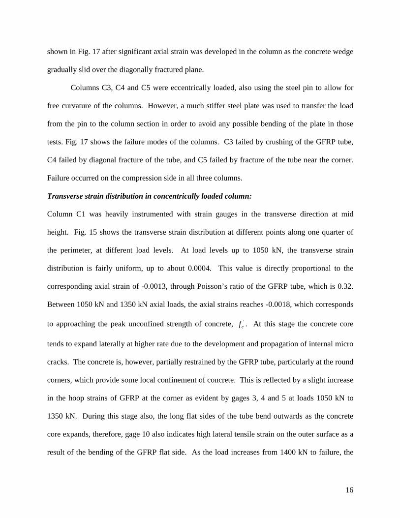
shown in Fig. 17 after significant axial strain was developed in the column as the concrete wedge
gradually slid over the diagonally fractured plane.
Columns C3, C4 and C5 were eccentrically loaded, also using the steel pin to allow for
free curvature of the columns. However, a much stiffer steel plate was used to transfer the load
from the pin to the column section in order to avoid any possible bending of the plate in those
tests. Fig. 17 shows the failure modes of the columns. C3 failed by crushing of the GFRP tube,
C4 failed by diagonal fracture of the tube, and C5 failed by fracture of the tube near the corner.
Failure occurred on the compression side in all three columns.
Transverse strain distribution in concentrically loaded column:
Column C1 was heavily instrumented with strain gauges in the transverse direction at mid
height. Fig. 15 shows the transverse strain distribution at different points along one quarter of
the perimeter, at different load levels. At load levels up to 1050 kN, the transverse strain
distribution is fairly uniform, up to about 0.0004. This value is directly proportional to the
corresponding axial strain of -0.0013, through Poisson’s ratio of the GFRP tube, which is 0.32.
Between 1050 kN and 1350 kN axial loads, the axial strains reaches -0.0018, which corresponds
to approaching the peak unconfined strength of concrete, 'cf . At this stage the concrete core
tends to expand laterally at higher rate due to the development and propagation of internal micro
cracks. The concrete is, however, partially restrained by the GFRP tube, particularly at the round
corners, which provide some local confinement of concrete. This is reflected by a slight increase
in the hoop strains of GFRP at the corner as evident by gages 3, 4 and 5 at loads 1050 kN to
1350 kN. During this stage also, the long flat sides of the tube bend outwards as the concrete
core expands, therefore, gage 10 also indicates high lateral tensile strain on the outer surface as a
result of the bending of the GFRP flat side. As the load increases from 1400 kN to failure, the
17
short flat side also starts to bend outwards as indicated by gage 1. At this stage, the hoop strain
at the round corner become stable and the flat sides continuously bulge outwards, which
indicates loss of confinement efficiency due to the loss of restraint.
Axial load – bending moment interaction diagram:
Based on the five concentric and eccentric column tests, C1 to C5, as well as the small beam test,
B3, several points on the beam-column interaction curve are obtained as shown in Fig. 16. The
figure shows that most of the data points are in the compression failure region due to the limited
range of eccentricities studied in this experimental investigation. This investigation was
controlled by applying an eccentric axial load with eccentricities less than (h/2), where h is the
depth of the section, in order to avoid instability of the specimen during testing. The interaction
curve is discussed in more details in a companion paper [Fam et al (2003a)], including analytical
modeling and a methodology for prediction of the full curve.
CONCLUSIONS
Rectangular concrete-filled FRP tubes (CFRFT) have been tested in this study in bending and
under eccentric and concentric axial compression loads. Based on this experimental investigation
the following conclusions are drawn:
1. CFRFT provides reliable and feasible structural members for beam and column applications.
The system is quite simple in construction as the FRP tube provides permanent formwork and is
the sole reinforcement for concrete in the axial and transverse directions.
2. The laminate stress-strain behaviour of FRP tubes could be quite nonlinear. Laminates with
fibres oriented at ±45 degrees show significant nonlinearity under tension and compression.
Nonlinearity could also result from progressive failure of layers oriented at various directions.
18
3. The load-deflection behaviour of CFRFT beams is slightly non-linear due to the nonlinearity
of both FRP tube and concrete. The beam with inner void had 22 percent lower strength than the
totally filled beam; however, it was 56 percent lighter in weight.
4. Totally filled CFRFT beam failed by rupture of FRP in the tension side while the beam with a
void failed by inward buckling and fracture of the concrete compressive flange. In both breams
outward buckling of the FRP compressive flange was observed.
5. The depth of compression zone in CFRFT beams is stable after cracking at about 20 to 30
percent of the section depth, throughout the loading history. Linear strain distribution is also
observed.
6. For CFRFT beams, increasing the reinforcement ratio, which is the relative cross-sectional
areas of FRP and concrete, by 55 percent resulted in increasing flexural strength by 41 percent.
7. The flexural strength of CFRFT is comparable to that of concrete-filled steel tubes (CFRST)
of similar reinforcement ratio. Their load-deflection behaviour, however, is quite different.
CFRST are initially stiffer due to the higher Young’s modulus of steel compared to GFRP. Once
the steel yield, plastic behaviour is observed, whereas CFRFT do not show plasticity.
8. CFRFT columns loaded over the entire cross-section could fail in a brittle manner by fracture
of the FRP tube at the round corner, where a high level of bi-axial state of stresses is developed.
9. The round corners of CFRFT columns provide confinement initially; however, the flat sides
of the FRP tube bend outwards eventually and cause the column to bulge and the concrete core
to loose restraint. Consequently, the confinement effect is significantly reduced.
19
ACKNOWLEDGEMENT
The authors wish to acknowledge financial support provided by the Network of Centres of
Excellence on Intelligent Sensing for Innovative Structures (ISIS Canada), the University of
Manitoba, the Constructed Facilities Laboratory of North Carolina State University and
Composite Atlantic Ltd. The authors are also grateful to Jerry Atkinson for his assistance during
the experimental program.
NOTATIONS
b = Width of the rectangular cross-section
bw = Width of the rectangular cross-section, according to ACI 318-99
c = Neutral axis depth
d = Depth of the rectangular cross-section
e = Eccentricity of axial load
'cf = Concrete compressive strength
yf = Yield strength of steel and taken as the ultimate tensile strength of the
flange for FRP tubes
h = Depth of the rectangular cross-section
M = Bending moment
t = Thickness of GFRP flange
Vc = Shear force resisted by concrete
Vf = Shear force resisted by GFRP web
ρ = Reinforcement ratio
20
REFERENCES
1. ACI Committee 318 (1999) “Building Code Requirements for Reinforced Concrete and
Commentary,” ACI 318M-99/ACI 318RM-99, American Concrete Institute, Detroit.
2. ASTM D3039/D3039M-00 “Standard Test Method for Tensile Properties of Polymer Matrix
Composite Materials”.
3. Burgueno, R., Davol, A., and Seible F. (1998) “The Carbon Shell System for Modular Bridge
Components,” Proceeding of the First International Conference on Composites in
Infrastructure ICCI’96, Tucson Arizona, USA, Edited by H. Saadatmanesh and M.R. Ehsani,
Jan., pp.341-354.
4. Daniel, I. M., and Ishai, O. (1994) “Engineering Mechanics of Composite Materials,” Ed. by
Oxford University Press, New York.
5. Fam, A., Mandal, S., Rizkalla and S. (2003a) “Rectangular Filament Wound GFRP Tubes
Filled with Concrete under Flexural and Axial Loading: Analytical Modelingl”, ASCE
Journal of Structural Engineering, submitted for publication, September.
6. Fam, A., Flisak, B. and Rizkalla, S. (2003b) “Experimental and Analytical Investigations of
Concrete-Filled Fiber-Reinforced Polymer Tubes Subjected too Combined Bending and
Axial Loads”, ACI Structural Journal, Vol.100, No.4, July-August, pp. 499-509.
7. Fam, A. Z., and Rizkalla, S. H. (2001a) “Behavior of Axially Loaded Concrete-Filled
Circular Fiber Reinforced Polymer Tubes”, ACI Structural Journal, Vol.98, NO.3, May-
June, pp. 280-289.
8. Fam, A.Z., and Rizkalla, S.H., (2001b), “Confinement Model for Axially Loaded Concrete
Confined by FRP Tubes,” ACI Structural Journal, Vol. 98, No. 4, Jul.-Aug., pp.451-461.
21
9. Fardis, M. N. and Khalili, H. (1981) “Concrete Encased in Fibreglass-Reinforced Plastic,”
ACI Structural Journal, Title No. 78-38, Nov.-Dec., pp. 440-446.
10. Hall, J. E. and Mottram, J. T. (1998) “Combined FRP Reinforcement and Permanent
Formwork for Concrete Members,” ASCE Journal of Composites for Construction, Vol. 2,
No. 2, May, pp. 78-86
11. Kilpatrick, A. E. and Rangan B. V. (1997) “Tests on High-Strength Composite Concrete
Columns,” Research Report No. 1/97, School of Civil Engineering, Curtin University of
Technology, Perth, Western Australia, March.
12. Lu, Y. Q., and Kennedy, D. J. L. (1992) “The Flexural Behavior of Concrete-Filled Hollow
Structural Sections”, Structural Engineering Report 178, April, Department of Civil
Engineering, University of Alberta, Alberta, Canada.
13. Mirmiran, A., Shahawy, M., and Samaan, M. (1999) “Strength and Ductility of Hybrid FRP-
Concrete Beam-Columns.”, ASCE Journal of Structural Engineering, 125(10), 1085-1093.
14. Mirmiran, Amir et al (2000) “Large Beam-Column Tests on Concrete-Filled Composite
Tubes,” ACI Structural Journal, Title no. 97-S29, March-April, pp. 268-276.
15. Neville, A. M. (1968) “Properties of Concrete”, 2nd Ed., McGraw-Hill Book Company, New
York.
16. Tomii, Masahide and Sakino, Kenji (1979) “Experimental studies on the ultimate moment of
concrete filled square steel tubular beam-columns,” Translation of A.I.J., No. 275, Jan., pp.
55-65.
17. Triantafillou, T. C. and Meier, U. (1992) “Innovative design of FRP combined with
concrete,” Proceeding of the First International conference on Advanced Composite
Materials for bridges and Structures (ACMBS), Sherbrooke, Quebec. pp. 491-499.
22
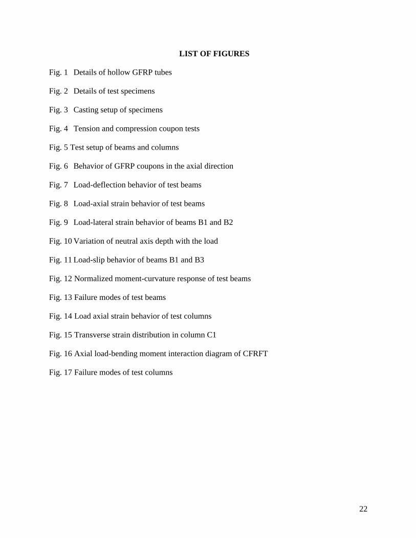
LIST OF FIGURES
Fig. 1 Details of hollow GFRP tubes
Fig. 2 Details of test specimens
Fig. 3 Casting setup of specimens
Fig. 4 Tension and compression coupon tests
Fig. 5 Test setup of beams and columns
Fig. 6 Behavior of GFRP coupons in the axial direction
Fig. 7 Load-deflection behavior of test beams
Fig. 8 Load-axial strain behavior of test beams
Fig. 9 Load-lateral strain behavior of beams B1 and B2
Fig. 10 Variation of neutral axis depth with the load
Fig. 11 Load-slip behavior of beams B1 and B3
Fig. 12 Normalized moment-curvature response of test beams
Fig. 13 Failure modes of test beams
Fig. 14 Load axial strain behavior of test columns
Fig. 15 Transverse strain distribution in column C1
Fig. 16 Axial load-bending moment interaction diagram of CFRFT
Fig. 17 Failure modes of test columns
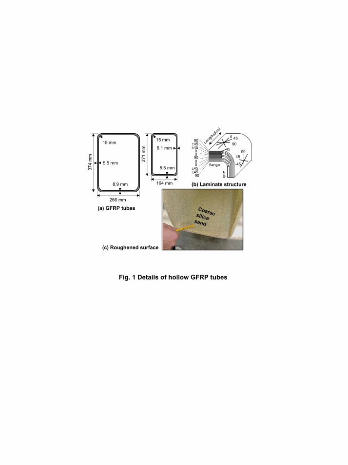
Fig. 1 Details of hollow GFRP tubes
164 mm
271
mm
15 mm
6.1 mm
8.5 mm374
mm
266 mm
8.9 mm
5.5 mm
15 mm 90
0 45
-45
90±45±45
0090
±45±45
00
90
(a) GFRP tubes
(b) Laminate structure
(c) Roughened surface
Coarse silicasand
90
-45
45
flange
web
Long
itudin
al
164 mm
271
mm
374
mm
266 mm
SpecimenID
B1
Type
Bea
m
B2B3C1C2C3C4C5
Col
umn
Cross -section
“a”“b”“c”
“c”
Test configuration
2100 mm
300 mm
680
mm
e
e
e = 0 (Pinned)e = 0 (Fixed)e = 25 mm (Pinned)e = 50 mm (Pinned)e = 64 mm (Pinned)
Pinned
Fixed
374
mm
266 mm
64 mm
34 mm
“a” “b” “c”
Fig. 2 Details of test specimens
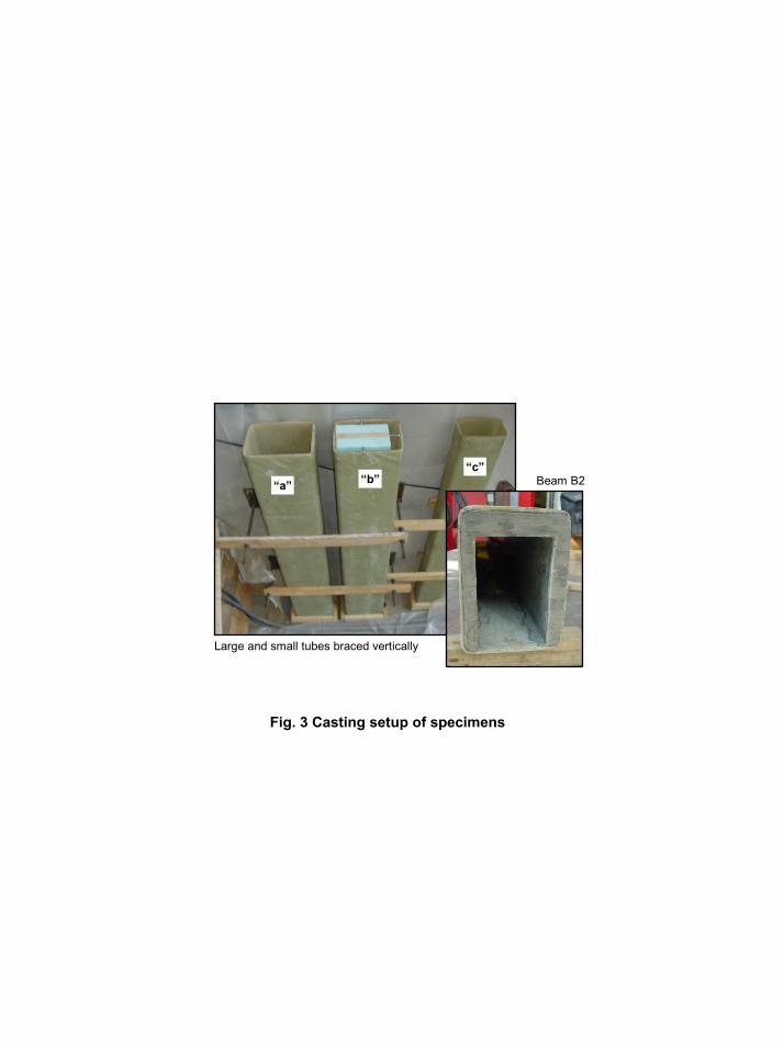
Fig. 3 Casting setup of specimens
Beam B2
Large and small tubes braced vertically
“a” “b”“c”
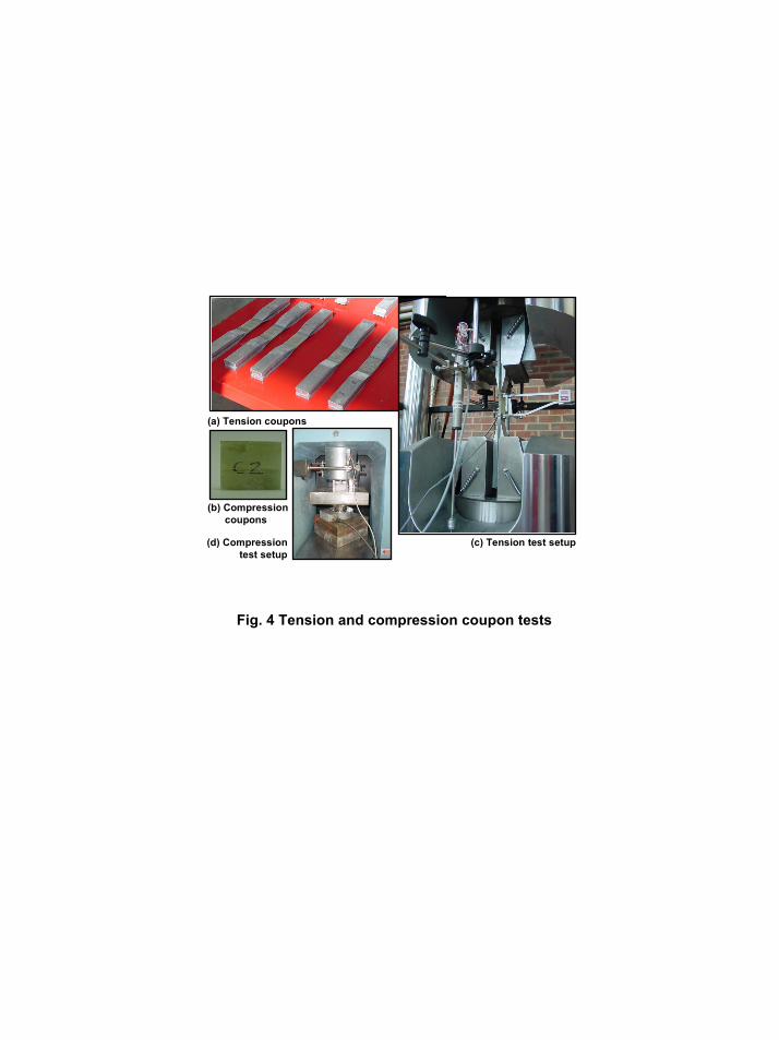
Fig. 4 Tension and compression coupon tests
(a) Tension coupons
(b) Compression coupons
(c) Tension test setup(d) Compressiontest setup
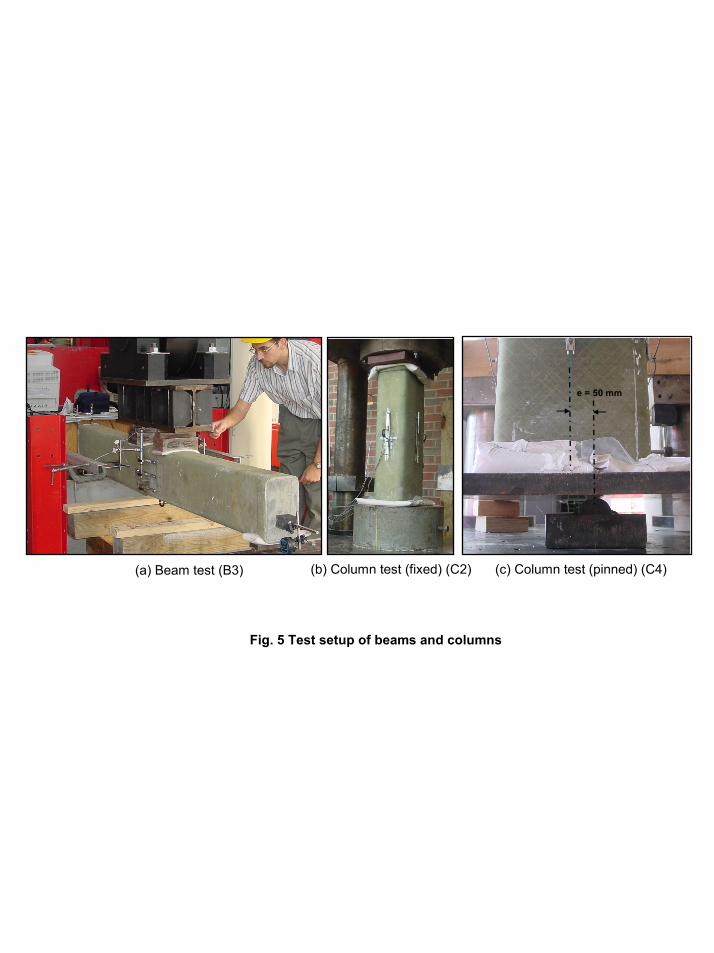
Fig. 5 Test setup of beams and columns
(a) Beam test (B3) (b) Column test (fixed) (C2) (c) Column test (pinned) (C4)
e = 50 mm
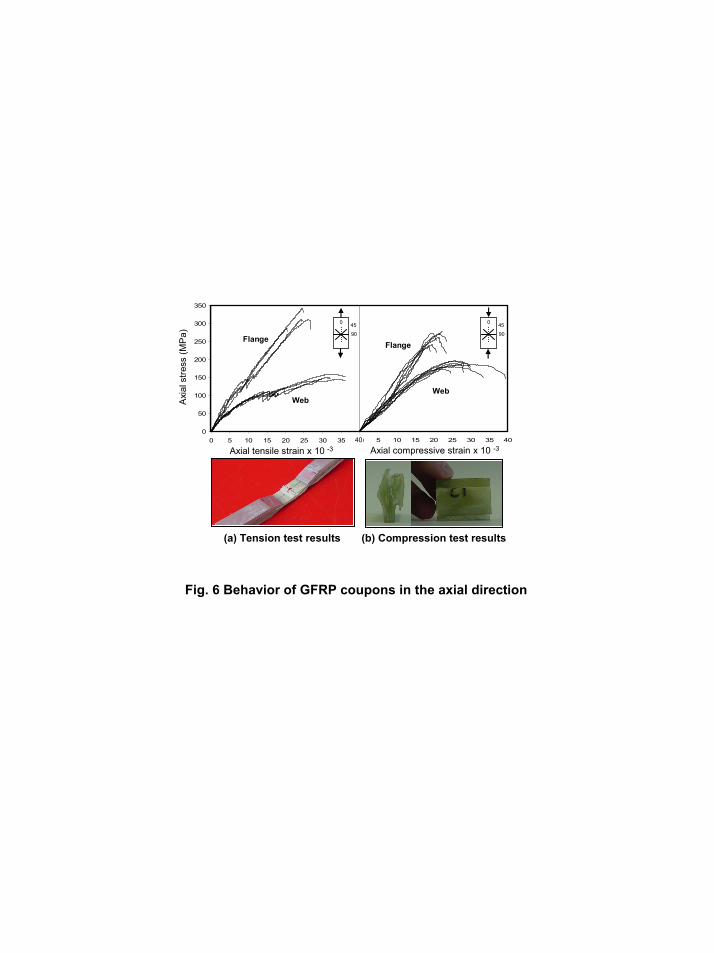
Fig. 6 Behavior of GFRP coupons in the axial direction
90
0
50
100
150
200
250
300
350
0 5 10 15 20 25 30 35 400 5 10 15 20 25 30 35 4040
Axi
al s
tress
(MP
a)
Axial tensile strain x 10 -3
0 45
90
0 45
Axial compressive strain x 10 -3
(a) Tension test results (b) Compression test results
Flange
Web
Flange
Web

Deflection (mm)
Load
(kN
)
0
100
200
300
400
500
600
700
0 10 20 30 40 50 60
B3
B1
B2
a
b
c
d
c
Fig. 7 Load-deflection behavior of test beams
0
100
200
300
400
500
600
700
-10 -5 0 5 10 15 20 25 30
Load
(kN
)
Axial strain x 10 -3
c
B3
B2
B1
Top (comp.) Bottom (ten.)
c
b d
Fig. 8 Load-axial strain behavior of test beams
0
100
200
300
400
500
600
700
-2 0 2 4 6 8 10 12 142 0 2 4 6 8 10 12 14
11023
23
64
12
34
12 34
11023
23
64
12
34
1 23 4b
b
14
B1 B2
Load
(kN
)
Lateral strain x 10 -3
Fig. 9 Load-lateral strain behavior of beams B1 and B2
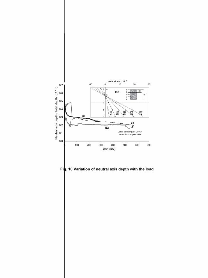
Fig. 10 Variation of neutral axis depth with the load
0.0
0.1
0.2
0.3
0.4
0.5
0.6
0.7
0 100 200 300 400 500 600 700
B1
Load (kN)
Neu
tral a
xis
dept
h / t
otal
dep
th (
C /
h)
B2
B3
-10 0 10 20 30
a
b
c
abcde
d
e
B3
60 kN
120 kN
180kN
240kN
300kN
Ch
Axial strain x 10 -3
Local buckling of GFRPtubes in compression
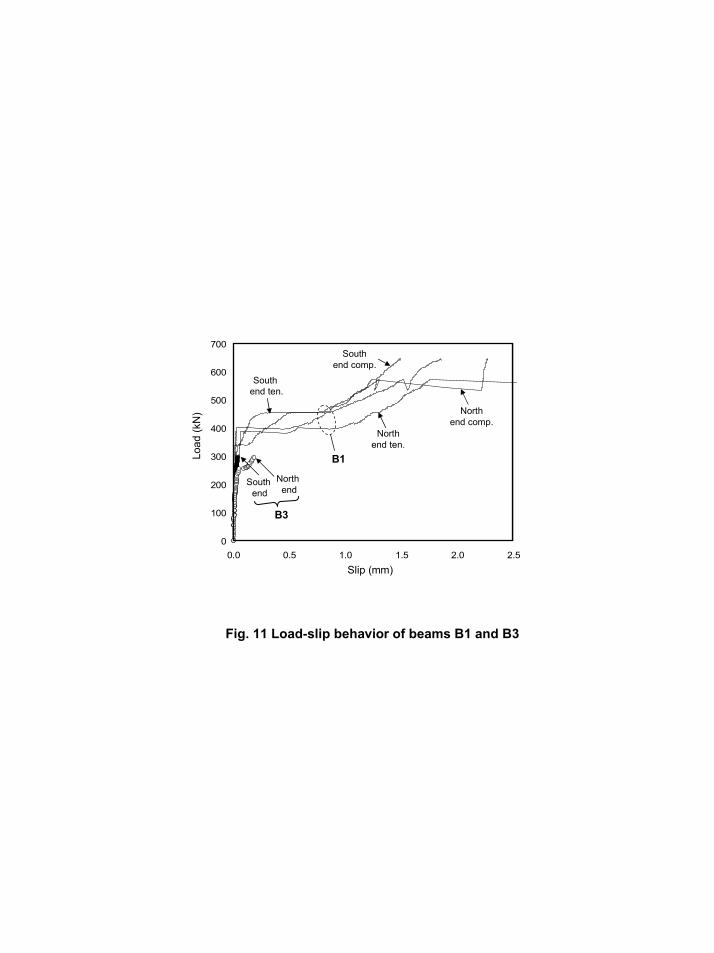
Fig. 11 Load-slip behavior of beams B1 and B3
South end
0
100
200
300
400
500
600
700
0.0 0.5 1.0 1.5 2.0 2.5
North end
B3
South end ten.
Northend ten.
Northend comp.
Southend comp.
B1
Slip (mm)
Load
(kN
)
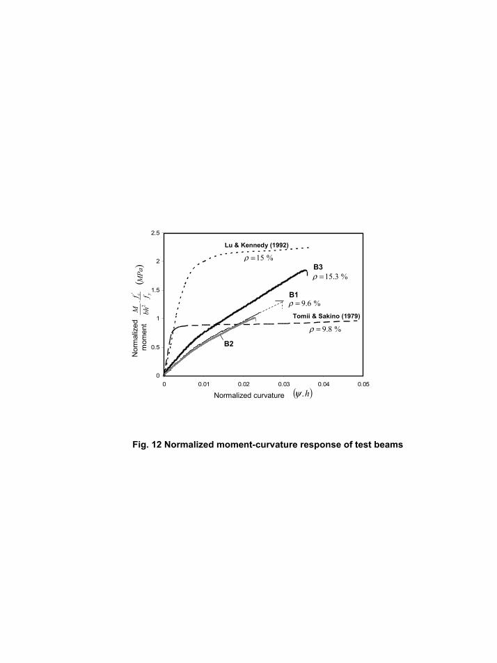
Fig. 12 Normalized moment-curvature response of test beams
0
0.5
1
1.5
2
2.5
0 0.01 0.02 0.03 0.04 0.05
Lu & Kennedy (1992)
Tomii & Sakino (1979)
B3
%6.9=ρ
%3.15=ρ
B1
B2
%15=ρ
%8.9=ρ
( )h.ψNormalized curvature
Nor
mal
ized
m
omen
t(
)MPa
ffbhM
yc'
2⋅
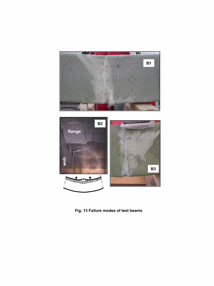
Fig. 13 Failure modes of test beams
B1
B2
B3
flange
web
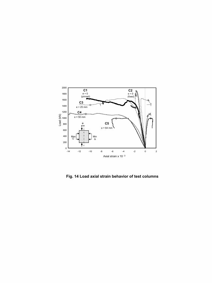
Fig. 14 Load axial strain behavior of test columns
e
Axial strain x 10 -3
Load
(kN
)
0
200
400
600
800
1000
1200
1400
1600
1800
2000
-14 -12 -10 -8 -6 -4 -2 0 2
Max Min
e = 64 mm
e = 50 mm
e = 25 mm
e = 0 (pinned)
e = 0 (fixed)
C1 C2
C3
C4
C5
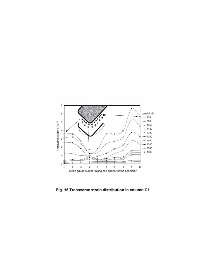
Fig. 15 Transverse strain distribution in column C1
0
1
2
3
4
5
6
7
1 2 3 4 5 6 7 8 9 10
20060010501130120013501400150015501638
12
34 5 6
78
910 Load (kN)
Strain gauge number along one quarter of the perimeter
Tran
sver
se s
train
x 1
0 -3
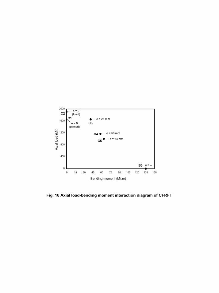
Fig. 16 Axial load-bending moment interaction diagram of CFRFT
0
400
800
1200
1600
2000
0 15 30 45 60 75 90 105 120 135 150
e = 0 (fixed)
e = 0 (pinned)
e = 25 mm
e = 50 mm
e = 64 mm
e = ∞
C1C2
C3
C4
C5
B3
Bending moment (kN.m)
Axi
al lo
ad (k
N)
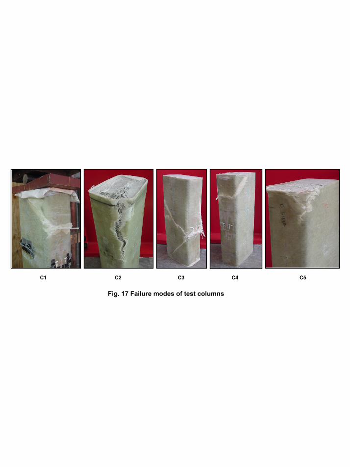
Fig. 17 Failure modes of test columns
C1 C2 C3 C4 C5


![SZ05-ZN/EN-A10€¦ · spring lever and withdraw filament 1. Pull filament guide tube out of filament intake, 2. Tap [Tools]. leave filament 10cm to pull filament easily. 5. Extruder](https://img.pdfslide.us/doc/110x75/5f8e7086182e8509724132b6/sz05-znen-a10-spring-lever-and-withdraw-filament-1-pull-filament-guide-tube-out.jpg)


![GFRP [Hand lay up]](https://img.pdfslide.us/doc/110x75/557cb1dcd8b42abf328b4c0e/gfrp-hand-lay-up.jpg)
![GFRP [Resin Infusion]](https://img.pdfslide.us/doc/110x75/546e67d4af795971298b5642/gfrp-resin-infusion.jpg)