Embed Size (px)
Citation preview

RECTANGULAR CLARIFIEREQUIPMENT & COMPONENTS

►Mechanical System Design
►Process System Design
►DAF Units
►Screw Conveyors
►Helical Skimmers
►Electrical Control Panels
►Wastewater Screens
►Start Up Services
►Rectangular Collectors
►Grit Collectors
►API Oil/Water Seperators
►Scum Troughs
►Flight Monitoring Systems
►Water Screens
►On Site Training
FAIRFIELD SUPPLIED ITEMS OF EQUIPMENT
www.fairfieldservice.com
FAIRFIELD SERVICE COMPANY
CALL : +1-740-387-3335 FAX : +1-740-387-4685
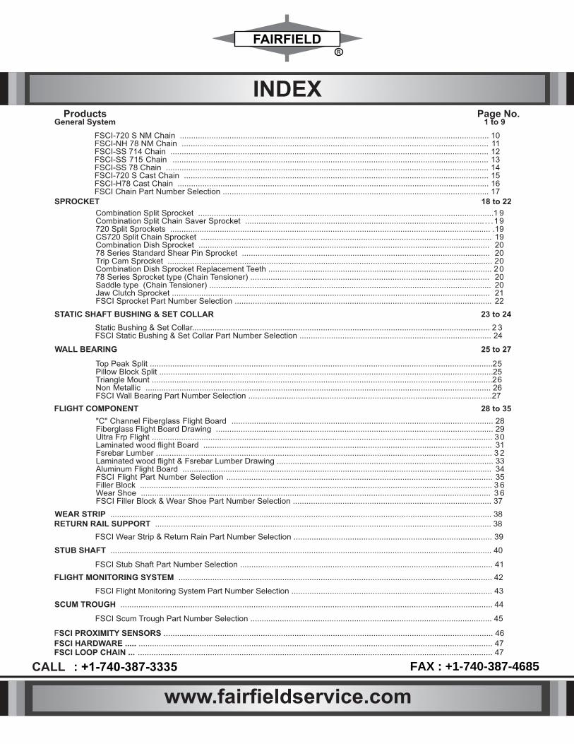
Products Page No.
INDEX
WEAR STRIP ......................................................................................................................................................................... 38 RETURN RAIL SUPPORT ..................................................................................................................................................... 38
FSCI Wear Strip & Return Rain Part Number Selection ........................................................................................ 39
STUB SHAFT ............................................................................................................................................................... .......... 40
FSCI Stub Shaft Part Number Selection ................................................................................................................ 41
FLIGHT MONITORING SYSTEM ........................................................................................................................................... 42
FSCI Flight Monitoring System Part Number Selection ......................................................................................... 43
SCUM TROUGH ..................................................................................................................................................................... 44
FSCI Scum Trough Part Number Selection ........................................................................................................... 45
FSCI PROXIMITY SENSORS .................................................................................................................................................. 46
FSCI HARDWARE ..... ................................................................................................................................................... .......... 47
FSCI-720 S NM Chain ......................................................................................................................................... 10FSCI-NH 78 NM Chain ........................................................................................................................................ 11FSCI-SS 714 Chain ............................................................................................................................................. 12FSCI-SS 715 Chain ............................................................................................................................................ 13FSCI-SS 78 Chain ............................................................................................................................................... 14FSCI-720 S Cast Chain ....................................................................................................................................... 15FSCI-H78 Cast Chain ....................................................................................................................................... ... 16FSCI Chain Part Number Selection .................................................................................................................... .. 17
General System
SPROCKET 18 to 22
Combination Split Sprocket ................................................................................................................................... 1 9 Combination Split Chain Saver Sprocket ......................................................................................................... . . . .19 720 Split Sprockets .......................................................................................................................................... .... . 19 CS720 Split Chain Sprocket ............................................................................................................................ ..... 19 Combination Dish Sprocket ............................................................................................................................. .... 20 78 Series Standard Shear Pin Sprocket .......................................................................................................... .... 20 Trip Cam Sprocket ........................................................................................................................................... ..... 20 Combination Dish Sprocket Replacement Teeth ................................................................................................... 20 78 Series Sprocket type (Chain Tensioner) ........................................................................................................ .. 20 Saddle type (Chain Tensioner) ........................................................................................................................... .. 20 Jaw Clutch Sprocket ......................................................................................................................................... .. .. 21 FSCI Sprocket Part Number Selection ................................................................................................................ .. 22
STATIC SHAFT BUSHING & SET COLLAR 23 to 24
Static Bushing & Set Collar.................................................................................................................................... 2 3 FSCI Static Bushing & Set Collar Part Number Selection ..................................................................................... 24
WALL BEARING 25 to 27
Top Peak Split ........................................................................................................................................................ 25 Pillow Block Split .................................................................................................................................................... 25 Triangle Mount ....................................................................................................................................................... 26 Non Metallic ......................................................................................................................................................... 26 FSCI Wall Bearing Part Number Selection ............................................................................................................27
FLIGHT COMPONENT 28 to 35
"C" Channel Fiberglass Flight Board .................................................................................................................... 28 Fiberglass Flight Board Drawing ....................................................................................................................... .... 29 Ultra Frp Flight ....................................................................................................................................................... 30 Laminated wood flight Board ............................................................................................................................ .... 31 Fsrebar Lumber ..................................................................................................................................................... 3 2 Laminated wood flight & Fsrebar Lumber Drawing ................................................................................................ 33 Aluminum Flight Board ...................................................................................................................................... ... 34 FSCI Flight Part Number Selection ...................................................................................................................... 35 Filler Block ............................................................................................................................................................ 3 6 Wear Shoe ........................................................................................................................................................... 3 6 FSCI Filler Block & Wear Shoe Part Number Selection ........................................................................................ 37
1 to 9
www.fairfieldservice.com
CALL : +1-740-387-3335 FAX : +1-740-387-4685FSCI LOOP CHAIN ... ................................................................................................................................................... .......... 47

Enviro Products
The Fairfield Chains Group-Enviro Division has been providing quality components for Municipal and Industrial Water & Wastewater applications for over 35 years.
System projects of all sizes are handled 100% by Fairfield Group. We continue to link a chain of satisfied clients around the world.
Our years of chain experience supports our application and engineering promise of being a "solution provider". We believe it’s essential to provide on site service and client consultation to properly assess the customer's goals and individual application requirements.
Our quality products include Chain, Sprockets, Flights, Wear Shoes, Bearings, Shafts, and Static Sleeve Bushings. Practically every consumable in Clarifiers, Grit Channels, Bar Screens, Traveling Water Screens for all water and waste water applications are supplied by Fairfield.
Fairfield Chains Group Enviro Division Your System Provider
CHAIN
www.fairfieldservice.com
CALL : +1-740-387-3335 FAX : +1-740-387-4685
1

FAIRFIELD SERVICE COMPANY
Fairfield Service Company was officially formed in 1978 as a subsidiary of Fairfield
Engineering Company, which was founded in 1919. The FAIRFIELD SERVICE COMPANY
was formed to fulfill Fairfield Engineering Company's desire to expand its material handling knowl-
edge into the municipal Wastewater treatment industries.
Today, Fairfield Service Company offers a wide variety of wastewater headworks and conveying equipment to accommodate the requirements of both new and existing facilities. FSCI also offers a diverse background in the design and manufacturing of custom-built equipment resulting from Fairfield Engineering Company's many years of experience in servicing the municipal and industrial markets.
FSCI utilizes industry leading technology to combine all disciplines of experience and technical knowledge for generating design, details, and calculations for the convenience of the customer and improved efficiency of operation.
At Fairfield Service company our most important business is satisfying our customer's goals, along with supplying state-of-the-art equipment and developing modern innovations to treat the water resources for today's and future generations.
> BAR SCREENS
THE CLAW Rack & Pinion Front Clean Front Return
THE MACH Chain & Sprocket Front Clean / Back Clean Front Front / Back Return
CANTENARY Chain & Sprocket Catenary Front clean Back Return
THE CAF Cable Front Front Clean Back Return
HFF Hydraulic Front Clean Front Return
LOCK LINK
TRAVELING WATER SCREEING
> FINE SCREENS
ROTARY DRUM SCREEN
STREAM GUARD
> COMPACTORS CONVEYORS
SCREW COMPACTOR (SCREENING WASHING / COMPACTOR)
BELT CONVEYORS
SCREW CONVEYORS (SHAFTED & SHAFT LESS)
> GRIT COLLECTORS
BELT CONVEYORS
SCREW CONVEYORS
SB
AERATED
BUCKET ELEVATORS
> SLUDGE COLLECTORS
LONGITUDINAL COLLECTORS
CROSS COLLECTORS
> TRASHRAKES
Upon request, we can provide information on:
Composting Equipment Live Bottom Bins
Flex-O-Wall Type Conveyors Vertical and C-type Conveyors
Drag Conveyors
Radial Stacking Conveyors Shuttle Conveyors
Chain & Bucket
Chain & Flight
Screw & Elevator
Grit Screw
www.fairfieldservice.com
CALL : +1-740-387-3335 FAX : +1-740-387-4685
2

GENERAL SYSTEMSThree Shaft System
A Three Shaft System is usually encountered where only solids are to be removed from a settling
tank. With this system, ights sweep the settled debris to a sludge hopper (as shown in the image
below), where they are pumped away or removed by a cross collector system. Such systems are
typically used for primary treatment where oating debris is not abundant. For secondary treatment
and scum removal a Four Shaft System is typically used.
Four Shaft System
Water surface skimming as well as displacing settled solids can be achieved through use of a
Four Shaft System. Debris such as scum, oil and grease can be removed efciently through
such collectors. This design can be used either as a primary
clarier as well as a secondary clarier.
www.fairfieldservice.com
CALL : +1-740-387-3335 FAX : +1-740-387-4685
3

Screw Conveyor Cross Collector
A Screw Conveyor Cross Collector may be used as an alternative to Chain and Flight Cross
Collectors. It serves the same purpose of concentrating the sludge into a sump pit. This system
can either be driven directly by a motor or indirectly by a chain drive system (as show in the image
below). A long single hopper or span of many hoppers can be accommodated. Hanger bearings
may be required depending on overall screw conveyor length.
Scum Trough Rotary Skimmers
From a design point of view, a Rotary Skimmer is the most economical and most common type
of surface scum skimmer. It can be operated either manually (as shown), or through a motor, to
accept scum oating on the water surface in a four shaft collector system.
GENERAL SYSTEMS
www.fairfieldservice.com
CALL : +1-740-387-3335 FAX : +1-740-387-4685
4

1"
2'
15
'-1
0"
"8
DR
IVE
SP
RO
CK
ET
AN
CH
OR
`F
OR
EA
CH
WE
DG
E
RE
DU
CE
R B
AS
E
2 N
OS
. E
XT
EN
SIO
N P
LA
TE
DR
IVE
SP
RO
CK
ET
SH
AF
T
HE
AD
SH
AF
T
DR
IVE
SP
RO
CK
ET
CO
LLE
CT
OR
CH
AIN
ST
UB
SH
AF
T A
SS
EM
BLY
CH
AIN
TIG
HT
EN
ER
BR
AC
KE
T`
BE
AR
ING
FLO
OR
WE
AR
ST
RIP
TY
PIC
AL
RE
CTA
NG
UL
AR
CL
AR
IFIE
RS
(SIN
GL
E L
AY
ER
)
www.fairfieldservice.com
CALL : +1-740-387-3335 FAX : +1-740-387-4685
5

SE
VE
N S
HA
FT
RE
CTA
NG
UL
AR
CL
AR
IFIE
RS
(
DU
AL
LA
YE
R)
DR
IVE
UN
IT
40
T D
RIV
EN
S
PR
OC
KE
T
11 T
DR
IVE
S
PR
OC
KE
T
SC
UM
SC
UM
DR
IVE
UN
IT
SK
IMM
ER
FL
IGH
T A
SS
EM
BLY
NM
72
0 S
CH
AIN
17
T I
DL
ER
S
PR
OC
KE
T
23
T S
PR
OC
KE
T
ST
UB
SH
AF
T
AS
SM
EB
LY
TE
LE
SC
OP
IC S
HA
FT
ZE
RO
SP
EE
D
S
WIT
CH
Seve
n s
haft c
lass
iers
can b
e a
ssum
ed a
s dual l
aye
r cl
assi
er.
T
he a
dva
nta
geous
poin
t here
is that th
e e
ffect
ive c
leanin
g c
apacity is
double
d e
ven w
ith the s
am
e s
urf
ace
are
a a
s th
at of fo
ur
shaft c
lassi
er.
www.fairfieldservice.com
CALL : +1-740-387-3335 FAX : +1-740-387-4685
6

DA
F S
LU
DG
E C
OL
LE
CT
OR
Dis
solv
ed A
ir F
loata
tion (
DA
F)
Cla
rie
r are
main
ly u
sed w
here
there
is a
need o
f re
movi
ng s
usp
ended s
olid
s fr
om
wate
r. T
he m
echanis
m o
f th
is
clarie
r in
cludes
em
issi
on o
f m
illio
ns
of m
icro
n s
ized b
ubble
s w
hic
h
oat
the s
olid
to the tank
surf
ace
form
ing a
conce
ntr
ate
d s
ludge b
lanket.
This
thic
k la
yer
is r
em
ove
d b
y a s
coop.
11 T
DR
IVE
S
PR
OC
KE
T
40 T
DR
IVE
N
S
PR
OC
KE
T D
RIV
E U
NIT
FLIG
HT
AS
SE
MB
LY
TE
LE
SC
OP
IC S
HA
FT
A
SS
EM
BLY
RE
TU
N R
AIL
17 T
SP
RO
CK
ET
AS
SE
MB
LY
ST
UB
SH
AF
T
www.fairfieldservice.com
CALL : +1-740-387-3335 FAX : +1-740-387-4685
7

FAIRFIELD SERVICE COMPANY
Head Shaft (Typical)
For a rectangular clarier, this shaft is considered as a driving shaft. It experiences greater forces
than other shafts and normally has the greatest diameter as compared to other shafts, also known
as idler shafts. Chain connected to the motor and reducer (drive) unit drives the driven sprocket.
Typically the head shaft is made of C1018 or C1045 steel, other material like SS-304, SS-316,
and tubular Fiberglass system are available. Wall bearings (which are supported with anchor bolts)
are usually made of cast iron with different contact surface liners but can be made of many materials
as per customer's request. The contact surface liners are usually of UHMW-PE or Babbitt. All
sprockets are keyed and locked with set screws so that the collector chains are aligned and move
together at the same rate. Keyways are adjusted in such a way that sprockets can be adjusted
along the shaft for proper alignment. To hold the shaft in place at the bearing, a set collar is used,
which can be made of variety of materials like UHMW-PE, cast iron, stainless steel and others as
per customer's request. Sprockets may be provided individually cast, but are typically of split
construction for easy assembly and future removal and replacement.
720 COLLECTOR SPROCKET
WALLBEARING
SET COLLAR
ANCHOR BOLTS
SHAFTING
KEY WAYS
720 COLLECTOR SPROCKET
WALL BEARING
www.fairfieldservice.com
CALL : +1-740-387-3335 FAX : +1-740-387-4685
8

AN
CH
OR
BO
LTS
ST
UB
SH
AF
T
72
0 C
OL
LE
CT
OR
SP
RO
CK
ET
SLE
EV
E B
EA
RIN
G
AN
CH
OR
BO
LTS
40T
SP
RO
CK
ET
ST
UB
SH
AF
T
TE
LE
SC
OP
ING
HE
AD
SH
AF
T (
OP
TIO
NA
L)
NO
N-M
ETA
LL
IC H
EA
D S
HA
FT
DE
SIG
N C
AN
BE
IN
STA
LL
ED
WIT
HO
UT
A C
RA
NE
. U
NIQ
UE
, L
IGH
TW
EIG
HT
AS
SE
MB
LYD
OE
S N
OT
RE
QU
IRE
AN
Y P
AIN
TIN
G O
R C
OA
TIN
G ,M
AK
ING
IT V
IRT
UA
LLY
MA
INT
EN
AN
CE
FR
EE
.M
AT
ER
IAL :
FR
P T
UB
E / M
.S. T
UB
E
SE
T C
OL
LA
R
72
0 C
OL
LE
CT
OR
SP
RO
CK
ET
TE
LE
SC
OP
IC S
HA
FT
AS
SE
MB
LY(3
PIE
CE
FR
P S
HA
FT
)
SLE
EV
E B
EA
RIN
G
SH
AF
T K
EY
SE
T C
OL
LA
R
SH
AF
T
KE
Y
TE
LE
SC
OP
IC S
HA
FT
(O
PT
ION
AL
)
www.fairfieldservice.com
CALL : +1-740-387-3335 FAX : +1-740-387-4685
9

FSCI-NM 720S CHAIN CHAIN SPECIFICATION:
Non-Metallic Collector Chain
► 6.00" Pitch
► Nylon Material (1013 B)
► 3,100 lb. Working Load
► 6,000 lb. Average, Ultimate Strength
► 1.5 lbs Per Foot Approx.
► Nylon Material Pin With Aluminum Insert
ATTACHMENTS AVAILABLE: ► F226 and F228 (5’ or 10’ spacings)
CHAIN APPLICATION: ► Collector chain for primary and secondary clarifiers.
BENEFITS:
FSCI-720S Non-Metallic Chain is lightweight and designed for easy installation. No special tools are required for
chain assembly. Chain is compatible with other chain manufacturer's non-metallic sprockets and components.
Dimensions, Weight and Strength of FSCI-720S Non-Metallic Chain
Chain Part No FFCBN720N00NT0AA 6.00
Pitch (inches)
1.5
Weight (lbs)
3,100
Working Load (lbs/ft)
1.414
Barrel Diameter (inches)
0.875
Pin Diameter (inches)
ATTACHMENT DATA :FSCI-720S NON-METALLIC/F228 & F226 (Fig. 2)
Fig. 2
FFCBN720NA8NT0A0
FFCBN720NA6NT0A0
3.00 8.00 5.625 2.375 4.50 0.33 3.75 5.50 0.438
Attachment Part No. A B C D E F G H Hole Dia.
3.00 6.125 3.750 2.375 2.63 0.33 3.75 5.50 0.438
FSCI-720S NON-METALLIC CHAIN
H
HOLE DIA
G
B
C
A F
DE
Fig. 1
21 1
6"
15 1
6"
41 4"
31 1
6"
PIN CAP
LINKRETAINING PIN
PITCH 6" PITCH 6" PITCH 6"
21 4"
FSCI FSCIFSCI
720 S 720 S 720 S
FSCI
720 S
www.fairfieldservice.com
CALL : +1-740-387-3335 FAX : +1-740-387-4685
10

FSCI-NH78 CHAIN CHAIN SPECIFICATION: Non-Metallic Drive Chain
► Glass Filled Nylon Material ► 2.609" Pitch ► 316 Stainless Steel Knurled Pin► No Cotters, Clips► Standard 78 Series Sprockets
► Maximum Working Load 1,800 lbs
► 4,000 lbs Average Ultimate Strength
► UV Inhibited Highly Resistant
APPLICATIONS:
► Drive chain for wastewater treatment applications.
BENEFITS:
FSCI-NH78 chain is designed to run in both directions. Excellent performance in applications requiring high
Wearability and chain strength.
Dimensions, Weight and Strength of FSCI-NH78 Non-Metallic Chain
FFCANH78N006N0B0
Weight (lbs/ft.)
1.41
Maximum Permissible
Tensile Force (lbs.)
1800
Backflex Radius
(inches)
3
FSCI-NH78 NON-METALLIC CHAIN
1,1
25”
1,6
25”
0,375”
1,6
88”
2,9
06”
2,609”
PITCH
2,609”
PITCH
2,609”
PITCH
2,609”
PITCH 1,1
25”
0,875”O O
Attachment Part No.
www.fairfieldservice.com
CALL : +1-740-387-3335 FAX : +1-740-387-4685
11
700 SERIES STAINLESS CHAIN
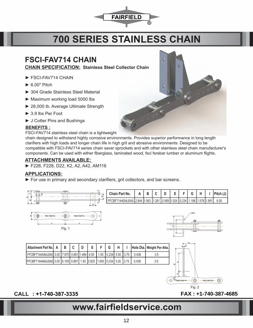
APPLICATIONS: ► For use in primary and secondary clarifiers, grit collectors, and bar screens.
ATTACHMENTS AVAILABLE: ► F226, F228, D22, K2, A2, A42, AM116
BENEFITS : FSCI-FAV714 stainless steel chain is a lightweight chain designed to withstand highly corrosive environments. Provides superior performance in long length clarifiers with high loads and longer chain life in high grit and abrasive environments. Designed to be compatible with FSCI-FAV714 series chain saver sprockets and with other stainless steel chain manufacturer's components. Can be used with either fiberglass, laminated wood, fsci fsrebar lumber or aluminum flights.
A
BC D
E
FF
GI
JJ
H
Chain Part No. A B C D E F G H I Pitch (J)
FFCBF7144004J0A0 2.844 1.563 1.281 0.569 1.024 0.234 1.188 1.578 1.891 6.00
3.00 6.109 0.891 1.50 2.625 1.093 0.234 5.50 3.75 0.438 2.6
A B C D E F G H I Hole Dia. Weight Per Atta.
FFCBF7144A84J0A0
FFCBF7144A64J0A0
3.00 7.875 0.891 1.484 4.50 1.00 0.234 5.50 3.75 0.438 3.5
Fig. 1
FSCI FAV714
A
B
G
E
H I
DIA.
D
C
Fig. 2
FSCI FAV714 FSCI FAV714
FSCI FAV714
► FSCI-FAV714 CHAIN
► 6.00" Pitch
► 304 Grade Stainless Steel Material
► Maximum working load 5000 lbs
► 28,000 lb. Average Ultimate Strength
► 3.9 lbs Per Foot
► J Cotter Pins and Bushings
FSCI-FAV714 CHAINCHAIN SPECIFICATION: Stainless Steel Collector Chain
Attachment Part No.
www.fairfieldservice.com
CALL : +1-740-387-3335 FAX : +1-740-387-4685
12

3.00 6.109 0.891 1.50 2.625 1.093 0.234 5.50 3.75 0.438 2.6
Chain Part No. A B C D E F G H I Hole Dia. Weight Per Atta.
FFCBF7154A84J0A0
FFCBF7154A64J0A0
3.00 7.875 0.891 1.484 4.50 1.00 0.234 5.50 3.75 0.438 3.5
700 SERIES STAINLESS CHAIN
APPLICATIONS: For use in primary and secondary clarifiers, grit collectors, and bar screens.
ATTACHMENTS AVAILABLE: ► F226, F228, D22, K2, A2, A42, AM116
A
BC D
E
FF
GI
JJ
H
Chain Part No. A B C D E F G H I Pitch (J)
FFCBF7154004J0A0 2.844 1.563 1.281 0.569 1.024 0.234 1.188 1.578 1.891 6.00
Fig. 1
FSCI FAV715
A
B
G
E
H I
DIA.
D
C
Fig. 2
FSCI FAV715 FSCI FAV715
FSCI FAV715
BENEFITS : FSCI-FAV715 stainless steel chain is a lightweight chain designed to withstand highly corrosive environments. Provides superior performance in long length clarifiers with high loads and longer chain life in high grit and abrasive environments. Designed to be compatible with FSCI-FAV715 series chain saver sprockets and with other stainless steel chain manufacturer's components. Can be used with either fiberglass, laminated wood, fsci fsrebar lumber or aluminum flights.
► FSCI-FAV715 CHAIN
► 6.00" Pitch
► 403 Grade Stainless Steel Material (heat treated)
► Maximum working load 5000 lbs
► 33,000 lb. Average Ultimate Strength
► 3.9 lbs Per Foot
► Hardened Pins and Bushings
FSCI-FAV715 CHAINCHAIN SPECIFICATION: Stainless Steel Collector Chain
www.fairfieldservice.com
CALL : +1-740-387-3335 FAX : +1-740-387-4685
13
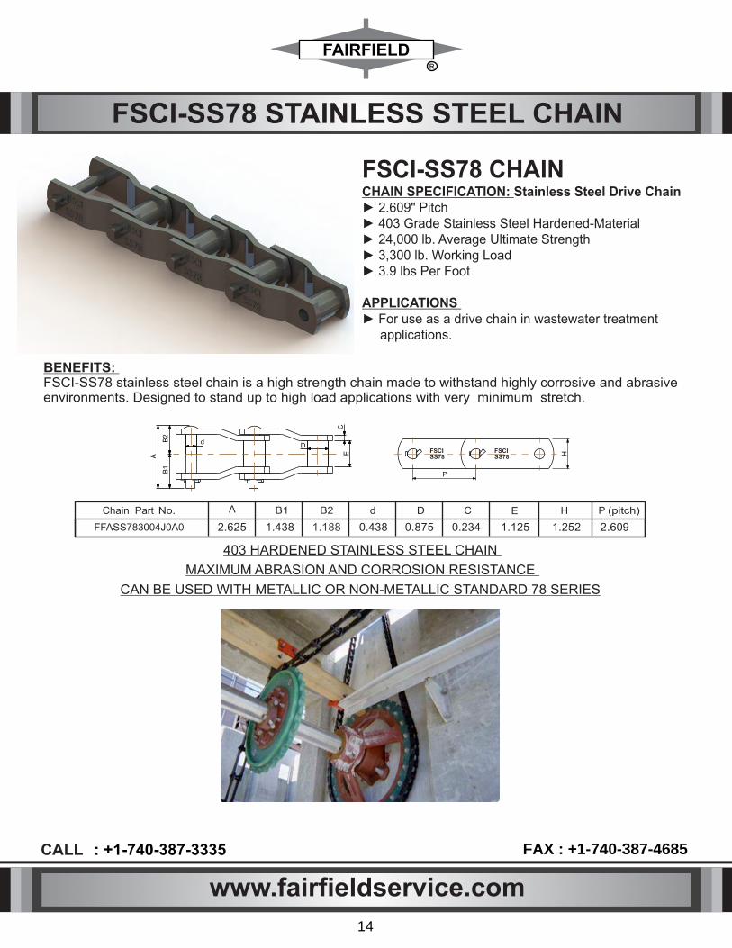
FSCI-SS78 CHAINCHAIN SPECIFICATION: Stainless Steel Drive Chain► 2.609" Pitch ► 403 Grade Stainless Steel Hardened-Material ► 24,000 lb. Average Ultimate Strength ► 3,300 lb. Working Load ► 3.9 lbs Per Foot
APPLICATIONS ► For use as a drive chain in wastewater treatment applications.
BENEFITS: FSCI-SS78 stainless steel chain is a high strength chain made to withstand highly corrosive and abrasive environments. Designed to stand up to high load applications with very minimum stretch.
403 HARDENED STAINLESS STEEL CHAIN
MAXIMUM ABRASION AND CORROSION RESISTANCE
CAN BE USED WITH METALLIC OR NON-METALLIC STANDARD 78 SERIES
FSCI-SS78 STAINLESS STEEL CHAIN
B2
B1
A
dD
C E
P
H
Chain Part No. A B1 B2 d D C E
FFASS783004J0A0 2.625 1.438 1.188 0.438 0.875 0.234 1.125
P (pitch)
2.609
H
1.252
FSCI SS78
FSCI SS78
www.fairfieldservice.com
CALL : +1-740-387-3335 FAX : +1-740-387-4685
14

FSCI CAST IRON CHAIN
ATTACHMENTS AVAILABLE
► F226. F228, A2I, A42, A53, AD474, Am116, F2. F3 (SF-4), K2, Ml.
APPLICATIONS
► For use in primary clarifiers, secondary clarifiers. bar screens and grit applications.
FSCI-720S CHAIN PMI
B C
DE
F G
PIN (COTTERED) PIN (RIVETED)
LINK
A H
6.00" PITCH 6.00" PITCH
FSCI 720S FSCI 720S
► FSCI-720S Cast Iron & SS Cast Chain offers maximum strength in harsh environments. This chain is
interchangeable with other chains manufactured under ANSI standards. Heat treated pin and 304
stainless steel cotter supplied specifically for wastewater applications.
Chain Part No. A B C D E F G
FFCBM7201004J0B0 .843 3.110 2.000 .250 .945 1.399 1.929
P (pitch)
6.00
H
1.575
Chain Part No. A B C D E F G
FFCBM720C004J0B0 .843 3.110 2.000 .250 .945 1.399 1.929
P (pitch)
6.00
H
1.575
BENEFITS:
CHAIN SPECIFICATION: Pearlitic Malleable Cast Iron
► 6.00" Pitch
► Heat Treated Pin
► 304 Stainless Steel Cotter
► Cottered or Riveted
► Cottered or Riveted
► Maximum Working Load: 4,250 lbs.
► Average Ultimate Strength: 39,000 lbs.
► Weight: 5.2 lbs./ft.
CHAIN SPECIFICATION: Cast 17-4 Stainless Steel Chain
► 6.00" Pitch
► Heat Treated Pin
► Stainless Steel Cotter
► Cottered or Riveted
► Cottered or Riveted
► Maximum Working Load: 8,000 lbs.
► Average Ultimate Strength: 80,000 lbs.
► Weight: 5.8 lbs./ft.
Malleable Cast Iron Chain
17-4 Stainless Steel Cast Chain
www.fairfieldservice.com
CALL : +1-740-387-3335 FAX : +1-740-387-4685
15

FSCI CAST IRON CHAIN
FSCI-H78 Cast Iron & SS Chain offers maximum strength in harsh environments. This chain is interchangeable with other chains manufactured under ANSI standards. Heat treated pin and 304 stainless steelcotter supplied specifically for wastewater applications.
FSCI-H78 CHAIN PMI
G F E D C
PIN (COTTERED)PIN (RIVETED)
LINK
COTTER PIN
FSCI H78
FSCI H78
2.609" PITCH 2.609" PITCH
B
BENEFITS:
Chain Part No. A B C D E F G
2.609 1.118 1.850 0.88 0.5 1.929 2.756
P (pitch)
6.00
Chain Part No. A B C D E F G
FFCA0H78C004J0B0
FFCA0H781004J0B0
2.609 1.118 1.850 0.88 0.5 1.929 2.756
P (pitch)
6.00
APPLICATIONS ► For use as a drive chain in wastewater treatment applications.
CHAIN SPECIFICATION: Pearlitic Malleable Cast Iron Chain ► 2.609" Pitch
► Heat Treated Pin
► Drive Chain
► 304 Stainless Steel Cotter
► Meets ANSI Standards
► Cottered or Riveted
► Maximum Working Load: 2,850 lbs.
► Average Ultimate Strength: 22,300 lbs.
► Weight: 4.2 lbs./ft.
CHAIN SPECIFICATION: Cast 17-4 Stainless Steel Chain ► 2.609" Pitch
► Heat Treated Pin
► Drive Chain
► Stainless Steel Cotter
► Meets ANSI Standards
► Cottered or Riveted
► Maximum Working Load: 4,500 lbs.
► Average Ultimate Strength: 35,000 lbs.
► Weight: 4.6 lbs./ft.
Malleable Cast Iron Chain
17-4 Stainless Steel Cast Chain
www.fairfieldservice.com
CALL : +1-740-387-3335 FAX : +1-740-387-4685
16

FSCI CHAIN PART NUMBER SELECTION
F F C B F 7 1 5 3 A 6 4 J A A A
FAIRFIELDSERVICE
COMPANY FF=
CHAIN TYPE
FSCI CHAIN PART NUMBER SELECTION
C = CHAIN
CHAIN PITCHA = 2.609
B = 6
Nh78 = NH78 CHAIN F714 = 714 CHAINF715 = 715 CHAIN
SS78 = SS78 CHAINHB78 = HB78 CHAIN
N720 = NON METALLIC 720S CHAINM720 = METALLIC 720S CHAIN
0H78 = H78 CHAIN
CHAIN MATERIAL3 = 403SS
N = NYLON4 = 304 SS6 = 316 SS0 = 410 SS
C = CAST IRON P = POLYESTER
A = ACTEL1 = 17-4SS ATTACHMENT
DETAILA = WITH ATTACHMENT
0 = WITH OUT ATTACHMENT
ATTACHMENTTYPE
6 = F 2268 = F 228
A = AM1162 = F23 = F3
CHAIN PIN MAT4 = 304SS6 = 316SS3 = 403SSP = POM
N = NYLON
ATTACHMENTAT EVERY
5 FT OR 10 FTA = 10 FTB = 5 FT
O = NOT REQUIRE
CHAIN SURFACEFINISH TYPEA = POLISH
B = MOLDEDC = RUF
CHAIN STRANDLENGTHA = 10 FTB = 5 FT
PIN TYPEJ = J COTTERED
R = RIVETEDN = KNURLING T = THREADED
www.fairfieldservice.com
CALL : +1-740-387-3335 FAX : +1-740-387-4685
17

SPROCKET DESIGNS AVAILABLE ALL UHMW SPROCKETS & ALL UHMW SEGMENTAL RIM SPROCKETS
CAST IRON CHILLED RIM SPROCKETSCOMBINATION SPROCKETS - CAST IRONBODY WITH UHMW SEGMENTAL RIMS
Cast Nylon Sprockets and Stainless Steel Sprockets also available
FSCI SPROCKET
www.fairfieldservice.com
CALL : +1-740-387-3335 FAX : +1-740-387-4685
18

PC
D
O.D
.
BO
RE
HU
B D
IA.
LTB.
15/16
(BlackGray Color)
Combination Split Chain Saver Sprocket Material: Ductile Iron hub & UHMW or S.S. or Harden Steel Sprocket
Combination Split Sprocket
Material: Ductile
Gray
Iron
hub
&
UHMW
or
S.S.
or
Harden
Steel
Sprocket
(Black
Color)
720 Split Sprockets, Chain Pitch: 6.000 Material: UHMW (Black Color) Roller Diameter 1-3/8"
Part No.
TeethNo.
13 17 19 21 23 25
OutsideDia. 13.50 17.09 18.95 20.83 22.71 24.60
Bore Stock (in.)
1 1-3/4 1-3/4 1-3/4 1-3/4 1-3/4
Max. Drive
4
3-1/4 3-15/16 3-15/16 3-15/16 3-15/16 -1/2
Max Idler3-5/8 5.00 5.00 5.00 5.00 6.00
Hub Dia. 7 8-7/8 8-7/8 8-7/8 8-7/8 10-1/2
Nom. LTB
4 4 4 4 4 4
PitchDia.12.91 16.59 18.45 20.33 22.21 24.10
CS720 Split Chain Sprockets, Chain Pitch: 6.000 Material: UHMW (Black Color) Roller Diameter 1-7/16"
Part No.
Teeth No.
11
13
17
19
21
23
25
MediumSmall
3-1/2 to
3-1/2 to
3-1/2 to
3-1/2 to
3-1/2 to
3-1/2 to
3-1/2 to
4-15/16
4-15/16
4-15/16
4-15/16
4-15/16
4-15/16
4-15/16
Large
5.00 to
5-15/16
5.00 to
5-15/16
5.00 to
5-15/16
5.00 to
5-15/16
5.00 to
5-15/16
5.00 to 5-15/16
5.00 to 5-15/16
Max Drive Bore (in.)
1-1/2 to
1-1/2 to
1-1/2 to
1-1/2 to
1-1/2 to
1-1/2 to
1-1/2 to
3-7/16
3-7/16
3-7/16
3-7/16
3-7/16
3-7/16
3-7/16
Part No. Teeth No.
13
17
19
21 23 25
3-1/2 to 3-1/2 to 3-1/2 to 3-1/2 to 3-1/2 to 3-1/2 to
4-15/16
4-15/16
4-15/16
4-15/16 4-15/16 4-15/16
5.00
5.00
5.00
5.00 5.00 5.00
to 5-15/16
to 5-15/16
to 5-15/16
to 5-15/16 to 5-15/16 to 5-15/16
Max Drive Bore (in.)
1-1/2 to
1-1/2 to 1-1/2 to 1-1/2 to 1-1/2 to 1-1/2 to
3-7/16
3-7/16
3-7/16
3-7/16 3-7/16 3-7/16
MediumSmall Large
FSCI SPROCKET H
UB
DIA
.
Ch
ain
Sa
ver
Hu
b D
ia.
O.D
.
LTB.
PC
D
BO
RE
15/16
PC
D
THK
BO
RE
PC
D
THK
BO
RE
FB11SCU00000S060FB13SCU00000S060FB17SCU00000S060FB19SCU00000S060FB21SCU00000S060FB25SCU00000S060FB11SCU00000S060
FB13SCU00000SC64FB17SCU00000SC64FB19SCU00000SC64FB21SCU00000SC64FB23SCU00000SC64FB25SCU00000SC64
FB13SC000000S064FB17SC000000S064FB19SC000000S064FB21SC000000S064FB23SC000000S064FB25SC000000S064
TeethNo. Part No. 13
17 19 21 23 25
PitchDia. 12.91
16.59
18.45 20.33 22.21 24.10
OutsideDia.
13.50 17.09 18.95 20.83 22.71 24.60
Chain SaverHub. Dia.
13.50 17.09 18.95 20.83 22.71 24.60
BoreStock (In.)
1
1-3/4 1-3/4 1-3/4 1-3/4 1-3/4
Max. Drive3-1/4
3-15/16
3-15/16 3-15/16 3-15/16 4-1/2
MaxIdler3-5/8
5.00
5.00 5.00 5.00 6.00
HubDia.7
8-7/8 8-7/8 8-7/8 8-7/8
10-1/2
Nom. LTB
4
4 4 4 4 4
FB13SC000000SC64FB17SC000000SC64FB19SC000000SC64FB21SC000000SC64FB23SC000000SC64FB25SC000000SC64
www.fairfieldservice.com
CALL : +1-740-387-3335 FAX : +1-740-387-4685
19

FSCI SPROCKET
Part No.
FSCICHTN787TNYCIFSCICHTN788TNYCI
Teeth
No.
78
78
Series
Standard
Shear
Pin
Sprocket
Material:
Ductile
Gray
Iron
&
UHMW
(Black
color)
Part
No. Teeth
No. Pitch
Dia. Max.
Bore
A
B
C
D
FA11SCC35KS00060FA11SCC42KS00060
11
11 9.26
9.26 3.54.25
77.125
2.6863.1875
5.8115.875
7.258.25
Combination Dish Sprocket Replacement Teeth Material: UHMW (Black color)
Part No. Teeth No. BCD
Sold
in
segments with
teeth
per
segment
78
Series
Chain
Tensioner
Material: Sprocket Oil Filled nylon w/ UHMW (Black color) Bracket Material Carbon Steel or ductile iron
Part No. TeethNo.
Pitch Dia.
Max. Bore
A B c D E
FA11SNN250000060 11 9.26 2-1/2 5-5/8 4-1/2 4-7/16 5-5/8 14-1/4
Nylon (Green Color) (Black color)
Trip Cam Sprocket
Material: Oil Filled & UHMW
Shear
Pin
Material:
304
Stainless
Steel, Aluminum, Steel.
I I
I I
I I
I I
I I
ll e
Saddl type Chain Tensioner
Snap
Idler
Tensioner,
is
the
quickest
and
easiest
drive
chain
tensioner
to
install
on
the market
today.
Simply
mount
the
free-floating
assembly
around
the
drive
chain
strand
and using
the
adjustable
side
plates
reduce
slack
in
the
chain
to
the
optimum
location.
The
Snap Idler assembly does not require any anchor bolts to locate and place, and can be used with a wide variety of chain types.
Combination Dish Sprocket:- Material: Ductile Gray Iron & UHMW (Black color)I I The driven sprocket, also known as a bull gear, for the 78 chain that FSCI offers is the combination cast iron hub with attached UHMW segmented teeth. Cast iron hubs are stronger then non-metallic hubs and are longer lasting. This style sprocket is manufactured to fit the need of the tank's configuration with it's design capabilities of various offsets and pitch diameters.
Part No.
Teeth No.
Offset
FA40SNU0000AS06AFA40SCU0000BS06A
HUB MATERIAL : NYLON OR CITEETH MATERIAL : UHMW OR CI
ALSO 42 & 48 TEETH SEGMENT AVAILABLE
4040
6.5”6”
0.5 0.25 7900 9500
0.5 0.31 12000 15000
0.5 0.38 17000 21500
0.75 0.44 23650 29000
0.75 0.5 31500 38000
Shear Pin Dia. Inch
Shear Pin Neck Dia. inch
At Distance 'B' = 2.686" Torque (Lb-in)
At Distance 'B' = 3.1875" Torque (Lb-in)
FA11SOU00000060FA21SOU00000060FA23SOU00000060FA40SOU00000060FA40SOU00000060
1121234040
9.2620.3622.232930
www.fairfieldservice.com
CALL : +1-740-387-3335 FAX : +1-740-387-4685
20
CA
D
B

• Non-metallic shear pin sprockets will protect down line equipment without threat of seizure due to corrosion.
• Special tooth and bore size are available upon request.
• A shear pin is included in each unit.
• Will not rust.
• Replaceable sprocket rim.
• Easy installation.
• Nylon 6 and 304SS hardware are standard materials.
• Available in universal, clockwise, and counterclockwise rotation.
FSCI JAW CLUTCH SPROCKET
E
F
G
D
A B C
FSCI JAW CLUTCH SHEAR PIN DRIVE SPROCKET ASSEMBLY (NON METALLIC)
Chain Part No. A B C D E F G OF TEETH PITCH DIA MAX. BORE
FA11SNN250000060 3.5 2.75 3 12.38 7.125 4.5 .875 11 2.509.26
www.fairfieldservice.com
CALL : +1-740-387-3335 FAX : +1-740-387-4685
21

FSCI SPROCKET PART NUMBER SELECTION
F B 1 7 S N N 3 4 0 0 0 S C 6 B
FAIRFIELDSERVICE
COMPANY F=
HUB OFFSETA = 6.5"B = 6"
FSCI SPROCKET PART NUMBER SELECTION
S=STANDARD SHEAR PIN AS PER BORE SIZE
K = STANDARD KEY WAY AS PER BORE SIZE
CHAIN PITCH A = 2.609''
B=6''
NUMBER OF TEETH
10, 11, 17, 19, 21, 23, 40, 42, 48
S = SPROCKET
HUB MATERIALN = NYLON
P = POLYURETHANE C = CAST IRON
TEETH SEGMENT MATERIAL
N = NYLON P = POLYURETHANE
C = CAST IRONU = UHMW
BORE SIZE19 = 1.9375"24 = 2.4375"29 = 2.9375"34 = 3.4375"39 = 3.9375"43 = 4.4375"49 = 4.9375"54 = 5.4375"59 = 5.9375"
C = CHAIN SAVER RIM
HUB LTBA = 6.25
B = 6C = 5.2
D = 5.25E = 5.125
F = 5G = 4
H = 1.5
6 = 316 FASTENERS4 = 304 FASTENERS
S = SPLIT CONSTRUCTION
www.fairfieldservice.com
CALL : +1-740-387-3335 FAX : +1-740-387-4685
22
0 = NOT APPLICABLE
0 = NOT APPLICABLE
0 = NOT APPLICABLE
0 = NOT APPLICABLE
0 = NOT APPLICABLE
G = GALVANIZED

Static Shaft Bushing - Split
FSCI STATIC SHAFT BUSHING & SET-COLLAR
I I
Set Collar
PART NO.
BORE
1-7/16 1-15/16 2-7/16 2-15/16 3-7/16 3-15/16 4-7/16 4-15/16 5-7/16
A
5 5 5 6 6 8 8 9 9
B
1 1 1 1-1/4 1-1/4 1-1/4 1-1/4 1-1/2 1-1/2
SET SCREW
3/8 1/2 5/8 3/4 3/4 3/4 3/4 3/4 3/4
EST. WT. 0.29 0.68 1.06 1.20 1.67 2.32 3.07 3.31 3.88
SPLIT
I I
Static shaft bushing clamp tight around the static idler shafts via bolts and set screws. The sprockets rotate about the outer diameter of the sleeve in between the two retaining ridges. The nylon or UHMW-PE sleeve provides a corrosion resistant and smooth bearing surface for the sprockets.
Set collars are made from a wide variety of materials such as UHMW, nylon, cast iron, stainless steel, or otherspecified materials. No matter the material, all set collars are supplied with stainless steel hardware. Set collars clamp on the shafting and are secured with setscrews. They prevent the axial motion of sprockets or the shafting itself into the wall bearings.
B
A
BORE
B
A
BORE
SOLID
SET SCREW
PART NO. BORE
1-7/16 1-15/16 2-7/16 2-15/16 3-7/16 3-15/16 4-7/16 4-15/16 5-7/16
A
5 5 5 6 6 8 8 9 9
B
1 1 1 1-1/4 1-1/4 1-1/4 1-1/4 1-1/2 1-1/2
3/8 1/2 5/8 3/4 3/4 3/4 3/4 3/4 3/4
EST. WT. 0.11 0.17 0.39 0.45 1.0 1.25 1.36 2.18 2.35
FSCISCNY14510106FSCISCNY19510106FSCISCNY24510106FSCISCNY29612106FSCISCNY34612106FSCISCNY39812106FSCISCNY44812106FSCISCNY49915106FSCISCNY54915106
FSCISCNY145101S6FSCISCNY195101S6FSCISCNY245101S6FSCISCNY296121S6FSCISCNY346121S6FSCISCNY398121S6FSCISCNY448121S6FSCISCNY499151S6FSCISCNY549151S6
Part No.
FSCISSNY92SS6343FSCISSNY92SS6393
Required
Sprocket
2-15/163-15/16
Max. Shaft
Size(ln.)
3.5
4
A
7.257.25
B
9.259.25
D
66
A
B
D
BORE
www.fairfieldservice.com
CALL : +1-740-387-3335 FAX : +1-740-387-4685
23
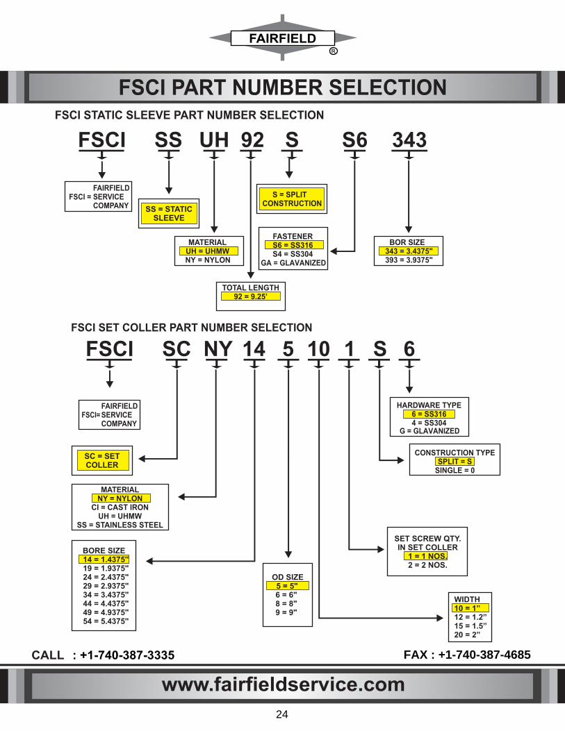
FSCI PART NUMBER SELECTIONFSCI STATIC SLEEVE PART NUMBER SELECTION
SC = SETCOLLER
OD SIZE5 = 5"6 = 6"8 = 8"9 = 9"
BORE SIZE14 = 1.4375"19 = 1.9375"24 = 2.4375"29 = 2.9375"34 = 3.4375"44 = 4.4375"49 = 4.9375"54 = 5.4375"
CONSTRUCTION TYPESPLIT = S
SINGLE = 0
FSCI SC NY 14 5 10 1 S 6
MATERIALNY = NYLON
CI = CAST IRONUH = UHMW
SS = STAINLESS STEEL
WIDTH10 = 1”12 = 1.2”15 = 1.5”20 = 2”
HARDWARE TYPE6 = SS3164 = SS304
FAIRFIELDSERVICECOMPANY
FSCI =
FAIRFIELDSERVICECOMPANY
FSCI=
SS = STATICSLEEVE
FSCI SS 92 S S6 343UH
S = SPLITCONSTRUCTION
MATERIALUH = UHMWNY = NYLON
BOR SIZE 343 = 3.4375"393 = 3.9375"
FASTENERS6 = SS316S4 = SS304
TOTAL LENGTH 92 = 9.25’
FSCI SET COLLER PART NUMBER SELECTION
SET SCREW QTY.IN SET COLLER
1 = 1 NOS.2 = 2 NOS.
www.fairfieldservice.com
CALL : +1-740-387-3335 FAX : +1-740-387-4685
24
GA = GLAVANIZED
G = GLAVANIZED

II
II
Top Peak Split
IIPillow Block Split
• Babbitted or UHMW lined • Split designs for ease of replacement • Bolt patterns designed to match most existing wall anchor locations for retrofit applications • Static shaftbrackets also available in conjunction with sprocket sleeve bearings
FSCI WALL BEARING
A
E
G
F
B B
C
SHAFT
DIA
1/8" NPTLUBE FTG.
H-BOLT DIA
3 1
/2
7 7
/4
9 1
/4
7 7
16 3/8
1
7
13 1
/2
4
45.0° 45.0°
1 5/16
X
BORE
2" RAD
DRILL THRU AND TAP 1/8" NPT
Brg.No. Shaft Dia.Dimensions (ln.) Wt. Lbs.
49
49
53
78
94
97
A
13
13
-
-
1/2
1/2
B
5
5
-
-
1/4
1/4
E
7
7
-
-
13/16
13/16
F G
1
1
-
-
1/8
1/8
H
1
1
4
4
-
-
1/4
1/4
5
5
-
-
1/4
1/4
13-1/2
14
14
14
5-1/4
5-1/2
5-1/2
5-1/2
7-9/16
8-3/8
11-1/8
11-1/4
1-1/8
1-1/8
1-1/4
1-1/4
1
1
1
1
4-3/16
4-3/4
6-1/2
6-1/2
5-5/8
6-3/8
7-1/4
8
C FSCIWBCIUHSOD193
FSCIWBCIUHSOD243
FSCIWBCIUHSOD293
FSCIWBCIUHSOD343
FSCIWBCIUHSOD393
FSCIWBCIUHSOD443
1 15/16
2 7/16
2 15/16
3 7/16
3 15/16
4 7/16
FSCIPBCIUHSOD193
FSCIPBCIUHSOD250
FSCIPBCIUHSOD300
FSCIPBCIUHSOD350
FSCIPBCIUHSOD400
FSCIPBCIUHSOD450
FSCIPBCIUHSOD500
Bore Range DIMENSIONSBearing No.
Min. Max. X ZWt. (lbs)
1 15/16
2 1/2
3
3 1/2
4
4 1/2
5
2 7/16
2 15/16
3 7/16
3 15/16
4 7/16
4 15/16
5 7/16
3
3 1/2
4
4 1/2
5
5 1/2
6
1 1/2
1 3/4
2
2 1/4
2 1/2
2 3/4
3
63
73
84
94
105
115
126
Wall Bearing
www.fairfieldservice.com
CALL : +1-740-387-3335 FAX : +1-740-387-4685
25

Material: UHMW
or
Poly
Urethane
Triangle
II
II Mount
II Non Metallic Pillow Block Split
FSCI WALL BEARING
B B
A
SH
AF
T D
IA
G
F
D
C
E
SHAFTDIA
H-BOLT DIA
BABBITTBEARING
BEARINGBRACKET
BEARING BLOCK
Dimensions (ln.)
A B C D E F G HFSCITBCIUH0M0193
FSCITBCIUH0M0250
FSCITBCIUH0M0300
FSCITBCIUH0M0350
FSCITBCIUH0M0400
FSCITBCIUH0M0450
FSCITBCIUH0M0500
1 15/16
2 7/16
2 15/16
3 7/16
3 15/16
4 7/16
4 15/16
7 1/2
8 1/4
9 3/4
10
11 1/4
12
13 5/8
2 3/8
2 3/4
3 3/8
3 1/2
4
4 3/8
5
3 1/8
3 9/16
4 5/16
4 13/16
5 3/8
5 1/2
6 1/2
1
3/4
3/4
3/4
3/4
5/8
5/8
5 5/8
6 5/16
7 5/16
8 3/8
9 5/16
9 3/4
11 1/8
4 1/2
5 1/4
5 5/8
6 3/8
7 1/4
8
8
1
1
1 1/8
1 1/8
1 1/4
1 1/4
1 1/4
3/4
3/4
7/8
7/8
1
1
1
18
22
36
40
54
65
95
BearingNo.
Shaft Dia.In.
Wt. (lbs.)
B
C
A
BOREF E
D
Bore Range DIMENSIONSBearing No.
Min. Max.
FSCIPBNYUHS0D193
FSCIPBNYUHS0D243
FSCIPBNYUHS0D293
FSCIPBNYUHS0D343
1 15/16
2 1/2
3
3 1/2
2 7/16
2 15/16
3 7/16
3 15/16
12
12
12
12
4.5
4.5
4.5
4.5
7.75
7.75
7.75
7.75
6.5
6.5
6.5
6.5
1.5
1.5
1.5
1.5
1
1
1
1
A B C D E F
www.fairfieldservice.com
CALL : +1-740-387-3335 FAX : +1-740-387-4685
26

FSCI BEARING PART NUMBER SELECTION
F S C I W B C I U H S M D 1 9 3
FAIRFIELDSERVICECOMPANY
FSCI=
FSCI BEARING PART NUMBER SELECTION
WB = WALL BEARINGPB = PILLOW BLOCK
BEARING HOUSING MATERIAL CI = CAST IRON
NY = NYLON
BUSH MATERIALNY = NYLONUH = UHMW
BB = BABBITEDCI = CAST IRON
S = SPLIT CONSTRUCTION
M = MOLDED BUSH TYPE
D = DETACHABLE BUSH TYPE
BORE SIZE193 = 1.9375"243 = 2.4375"293 = 2.9375"293 = 3.4375"343 = 3.4375"393 = 3.9375"443 = 4.4375"493 = 4.9375"543 = 5.4375"
www.fairfieldservice.com
CALL : +1-740-387-3335 FAX : +1-740-387-4685
27
0 = NOT APPLICABLE
0 = NOT APPLICABLE
0 = NOT APPLICABLE

High strength fiberglass, Ultra high-strength aluminum, Laminate it o replace existing redwood also available, Stainless steel hardware, 6 or 8 inch, available for standard F26 or F28 attachments.
APPLICATION: For use in primary clarifiers,
secondary clarifiers, and cross collectors.
SIZES: Standard 6" and 8"
MATERIAL: Fiberglass reinforced isophthalic
polyester resin (55% minimum glass content)
Also available; ►316 Stainless Steel Flight mounting Hardware Sets
►6" and 8" Filler Blocks
►Carry and Return Wearshoes
"C" CHANNEL FIBERGLASS FLIGHTBOARDS "C" CHANNEL FIBERGLASS FLIGHTBOARDS
FSCI FLIGHT COMPONENTS
6” OR 8” FLIGHT ATTACHMENT
6” OR 8” FILLER BLOCK
FLIGHT MOUNTINGHARDWARE
CARRY WEARSHOERETURN WEARSHOE
6” OR 8” SLUDGE FLIGHT
BENEFITS: Direct replacement for Wood flights, works with Plastic and Metallic Chains
WEIGHT: ► 6" = 1.21 lbs./ft.
► 8" = 1.39 lbs./ft.
Standard Flight
6 Inch nominal Description
Flight Specic Gravity 1.61 - 1.75
Flight Density (lbs./cubic inches) 0.058 - 0.062
Flight Min. Modulus of Elasticity (y-y axis) (psi) 4.8 x 10^6
Flight Moment of Inertia x-x (inches^4) 7.813
Flight Moment of Inertia y-y (inches^4) 1.02
8 Inch nominal
1.61 - 1.75
0.058 - 0.062
4.8 x 10^6
15.589
1.114
Fiberglass Flights:
The majority of ights are a "C" channel (6'' & 8'') model made from a minimum of 55% FIBERGLASS by content & maximum water ABSORPTION 0.6%.
FIBER GLASS FLIGHT :-
II
II
www.fairfieldservice.com
CALL : +1-740-387-3335 FAX : +1-740-387-4685
28

5
AB
CD
EF
GH
I
5
J
3
A
124
BC
DE
FG
HI
J
1234
SC
AL
E :
FA
IRF
IEL
D S
ER
VIC
E
CO
MP
AN
Y
IMP
LIE
D T
OL
ER
AN
CE
ST
ITL
E
FR
AC
TIO
NA
L D
IME
NS
ION
1/1
6
RE
V.
FO
R S
HE
AR
ING
, F
LA
ME
CU
TT
ING
,B
EN
DIN
G &
WE
LD
ME
NT
S A
FT
ER
WE
LD
ING
TH
IS D
RA
WIN
G A
ND
ALL D
ES
IGN
AN
D D
ETA
ILS
ON
IT
AR
E T
HE
P
RO
PE
RT
Y O
F T
HE
FA
IRF
IELD
SE
RV
ICE
CO
. O
F IN
D., L
LC
AN
D A
RE
C
ON
FID
EN
TIA
L.T
HE
DR
AW
ING
IS
NO
T T
O B
E C
OP
IED
WIT
HO
UT
P
ER
MIS
SIO
N A
ND
IS
RE
TU
RN
AB
LE
UP
ON
DE
MA
ND
. A
LL P
AT
EN
T
MA
CH
ININ
G ±
.X =
.06
AN
D D
ES
IGN
RIG
HT
S A
RE
RE
SE
RV
ED
.
.XX
X =
.0
02
.XX
=
.0
16
.XX
XX
=
.
00
05
DR
ILL
ING
+
.0
05
, -
.0
10
DR
AW
. N
O.
DA
TE
:
TE
MP
LA
TE
ME
AS
UR
EM
EN
T
M.P
.
MIC
HIG
AN
CIT
Y,
IND
IAN
AR
EV
ISIO
N
NO
RE
VIS
ION
DE
SC
RIP
TIO
NR
EV
. B
YD
AT
EA
PP
DN
OD
ES
CR
IPT
ION
RE
V.
BY
DA
TE
PR
OJE
CT
AP
PD
DR
AW
N
AN
GL
ES
=
0.1
CH
EC
KE
DR
FA
IRF
IEL
D
CU
ST
OM
ER
AP
PR
OV
AL
AP
PR
OV
ED
: [ ]
AP
PR
OV
ED
AS
NO
TE
D : [ ]
NO
T A
PP
RO
VE
DR
ES
UB
MIT
FO
R A
PP
RO
VA
L : [ ]
C
US
TO
ME
R : ____________
A
PP
RO
VE
D B
Y : _
___________
D
AT
E : _____________
P
K
F1
I
(T
YP
)1/2
L M
B
A
1/8
C
G
H
D
E
F2
JN
OO
FR
P F
LIG
HT
BO
AR
D
NO
TE
:(1
) F
LIG
HT
S S
HA
LL H
AV
E A
MIN
IMU
M O
F 5
5 %
FIB
ER
GL
AS
S B
Y C
ON
TE
NT
AN
D M
AX
IMU
M W
AT
ER
AB
SO
RP
TIO
N 0
.6%
.(2
) T
EN
SIL
E S
TR
EN
GT
H S
HA
LL B
E 3
5,0
00
PS
I L
ON
GIT
UD
INA
L A
ND
7,0
00
PS
I T
RA
NS
VE
RS
E.
(3)
SH
EA
R S
TR
EN
GT
H S
HA
LL B
E A
MIN
IMU
M O
F 1
4,0
00
PS
I.
(4)
MO
DU
LU
S O
F E
LA
ST
ICIT
Y S
HA
LL B
E A
MIN
IMU
M O
F 4
.8 X
10
6
PS
I IN
TH
E Y
-Y A
XIS
.(5
) C
ON
TR
AC
TO
R S
HA
LL V
ER
IFY
AL
L D
IME
NS
ION
,CO
ND
ITIO
NS
,AN
D Q
UA
NT
ITIE
S I
N T
HE
FIE
LD
.(6
) F
LIG
HT
S S
HA
LL B
E C
-CH
AN
NE
L F
UL
L S
IZE
AN
D B
E S
PE
CIF
ICA
LLY
DE
SIG
NE
D F
OR
SL
UD
GE
CO
LL
EC
TO
R S
ER
VIC
E
A
ND
CO
NS
TR
UC
TE
D O
F F
IBE
RG
LA
SS
RE
INF
OR
CE
D W
ITH
PO
LYS
TE
R R
ES
IN.
(7)
FL
IGH
TS
SH
AL
L H
AV
E C
ON
TIN
UO
US
FIB
ER
GL
AS
S F
ILA
ME
NT
S I
N A
DD
ITIO
N T
O A
FIB
ER
GL
AS
S M
AT
RU
NN
ING
T
HE
FU
LL L
EN
GT
H O
F T
HE
FL
IGH
T M
EM
BE
R.
www.fairfieldservice.com
CALL : +1-740-387-3335 FAX : +1-740-387-4685
29
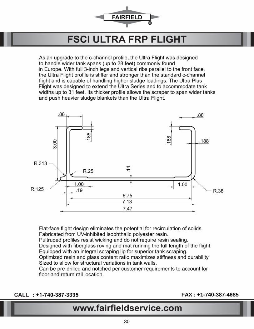
FSCI ULTRA FRP FLIGHT
Flat-face ight design eliminates the potential for recirculation of solids. Fabricated from UV-inhibited isophthalic polyester resin. Pultruded proles resist wicking and do not require resin sealing. Designed with berglass roving and mat running the full length of the ight. Equipped with an integral scraping lip for superior tank scraping. Optimized resin and glass content ratio maximizes stiffness and durability. Sized to allow for structural variations in tank walls. Can be pre-drilled and notched per customer requirements to account for oor and return rail location.
As an upgrade to the c-channel prole, the Ultra Flight was designed to handle wider tank spans (up to 28 feet) commonly found in Europe. With full 3-inch legs and vertical ribs parallel to the front face, the Ultra Flight prole is stiffer and stronger than the standard c-channel ight and is capable of handling higher sludge loadings. The Ultra Plus Flight was designed to extend the Ultra Series and to accommodate tank widths up to 31 feet. Its thicker prole allows the scraper to span wider tanksand push heavier sludge blankets than the Ultra Flight.
.88
.18
8
3.0
0
.88
.18
8
7.47
.19
7.136.75
R.313
R.125
R.25
R.38
.14
1.00 1.00
.188
www.fairfieldservice.com
CALL : +1-740-387-3335 FAX : +1-740-387-4685
30

FSCI FLIGHT COMPONENTS
LAMINATED WOOD FLIGHT BOARD APPLICATION:
►For use in primary clariers, secondary clariers,
and cross collectors.
SIZES:
►2 ½" X 6" = Standard 6"
►2 1/2" X 7 1/2" = Standard 8"
MATERIAL:
►Laminated Wood — Douglas Fir Kiln dried to 12% to 15%
moisture content with gradient not to exceed 5%.
BENEFITS:
Laminated wood ights come in a standard rectangular shape. The wood that is used for the ights is Douglas r and processed between 12-15% moisture. Laminated ights are normally used for heavy ow applications.
LAMINATED WOOD FLIGHTS :-
II
II
710
4.99 X 10^3
1.76 X 10^6
0.48
0.018495
87.8906
36
9.7656
4
Side hardness (lbs)
Modulus of rupture (psi)
Modulus of elasticity (psi)
Specic gravity
Density (Lbs./cubic inched)
8'' Moment of inertia X-X (inches^4)
6'' Moment of inertia X-X (inches^4)
8'' Moment of inertia Y-Y (inches^4)
6'' Moment of inertia Y-Y (inches^4)
I Decay hazard in wastewater applications much less than other wood ight alternatives. Long life in very
harsh environments.
www.fairfieldservice.com
CALL : +1-740-387-3335 FAX : +1-740-387-4685
31

FSCI FSREBAR LUMBER
TECHNICAL DATATECHNICAL DATA
Test Methods English units material units
FAIRFIELD “FSREBAR LUMBER” Plastic material properties
TestCompression ModulusCompression StrengthChemical Resistance Salt water
Chemical Resistance Gasoline
Chemical Resistance of Diesel
HardnessSpecific GravityFlesi pointWater AbsorptionThermal Expansion
Average Screw Pull OutFlame SpreadFlame Spread ClassificationSmoke DevelopedSmoke Developed ClassificationSpontaneous ignitionTenslie testNote hed impact resistance Method ABrattiness - Base materials
Abrasion resistanceHairinessUltreviolet :
Coefficient of Friction - StaticCoefficient of Friction - KineticFortnaldehyde gassing
ASTM TestD695D695ASTM D543ASTM D543/D638ASTM D543ASTM D543/D638ASTM D643ASTM D543 D638D4329D6111-97
D570D6341-98
D6117E84 (03al)E84 (03a)E84 (03a)E84 (03a)D-1929D638D256D746
D4060D4329D4329
D1849D1849D6007
Value170.000
450005
373629
3431098359667
0.93044025
0000035
64662602302508243623277<-40
Deg. C<0.023
66<10
0.2530.1730.02
Value
093340
293
440254
Unite
gccDegC
KG.
DegC2Kg/cm
UnitePSIPSI
by weightPSI - Tensite Dey snar.
%by WeightPSI- Tensile - 7 Day soak
% by WeightPSI - Tensile - 7 Day soak
Shore Dgice
Deg F% by Weight - 24 hour
Inch/Inch Deg F
Lbs.
Deg FPSI
FiLB IN
Grams(0.043%)Shore D
% Change in Type DDurointer at 50% hours
ppm
The tecnical data on page represents only average values and not minimum values fafetyfactors must be added into the design
Ultravioler WeatheringAn ultravioler stabilizer is added at the ume of manufacture to help protect against ultravioletdegradation of the plastic surface in exteror application
NON METALLICREINFORCING BAR
www.fairfieldservice.com
CALL : +1-740-387-3335 FAX : +1-740-387-4685
32

5
AB
CD
EF
GH
I
5
J
3
A
124
BC
DE
FG
HI
J
1234
SC
AL
E :
FA
IRF
IEL
D S
ER
VIC
E
CO
MP
AN
Y
IMP
LIE
D T
OLE
RA
NC
ES
TIT
LE
FR
AC
TIO
NA
L D
IME
NS
ION
1/1
6
RE
V.
FO
R S
HE
AR
ING
, F
LA
ME
CU
TT
ING
,B
EN
DIN
G &
WE
LD
ME
NT
S A
FT
ER
WE
LD
ING
TH
IS D
RA
WIN
G A
ND
AL
L D
ES
IGN
AN
D D
ETA
ILS
ON
IT
AR
E T
HE
P
RO
PE
RT
Y
OF
TH
E F
AIR
FIE
LD
SE
RV
ICE
CO
. O
F I
ND
., L
LC
AN
D A
RE
C
ON
FID
EN
TIA
L.T
HE
DR
AW
ING
IS
NO
T T
O B
E C
OP
IED
WIT
HO
UT
P
ER
MIS
SIO
N A
ND
IS
RE
TU
RN
AB
LE
UP
ON
DE
MA
ND
. AL
L P
AT
EN
T
MA
CH
ININ
G ±
.X =
.06
AN
D D
ES
IGN
RIG
HT
S A
RE
RE
SE
RV
ED
.
.XX
X =
.0
02
.XX
=
.0
16
.XX
XX
=
.
00
05
DR
ILL
ING
+
.0
05
, -
.0
10
DR
AW
. N
O.
DA
TE
:
MIC
HIG
AN
CIT
Y, IN
DIA
NA
RE
VIS
ION
M.P
.N
O
RE
VIS
ION
DE
SC
RIP
TIO
NR
EV
. B
YD
AT
EA
PP
DN
OD
ES
CR
IPT
ION
RE
V.
BY
DA
TE
PR
OJE
CT
AP
PD
DR
AW
N
AN
GL
ES
=
0.1
CH
EC
KE
DR
FA
IRF
IEL
D
CU
ST
OM
ER
AP
PR
OV
AL
AP
PR
OV
ED
:
[
]
AP
PR
OV
ED
AS
NO
TE
D :
[
]
NO
T A
PP
RO
VE
DR
ES
UB
MIT
FO
R A
PP
RO
VA
L :
[
]
CU
ST
OM
ER
:
_
__
__
__
__
__
_
AP
PR
OV
ED
BY
:
__
__
__
__
__
__
DA
TE
:
__
__
__
__
__
__
_ R
R
J
K L
M
P
A
B
C
135°
K E
D
G
T
YP
7/1
6
F1
Q
H
Q
F2
O
DA
P
FA
CE
DA
P
NO
TE
:(1
) T
HE
FL
IGH
TS
SH
AL
L B
E M
AD
E O
F W
ES
T C
OA
ST
DO
UG
LA
S F
IR,K
ILN
DR
IED
TO
12
% T
O 1
5
MO
IST
UR
E C
ON
TE
NT
WIT
H A
GR
AD
IEN
T N
OT
EX
CE
ED
ING
5%
, L
AM
INA
TIN
G S
HA
LL B
E I
N A
CC
OR
DA
NC
E W
ITH
AM
ER
ICA
N N
AT
ION
AL S
TA
ND
AR
D
(
AN
S I
I AIT
C-A
19
0)
19
83
. C
AM
BE
R L
AM
INA
TIO
N S
HA
LL B
E R
ES
OR
CIN
OL R
ES
IN.
(2)
CO
NT
RA
CT
OR
SH
AL
L V
ER
IFY
AL
L D
IME
NS
ION
S,C
ON
DIT
ION
S A
ND
QU
AN
TIT
ES
IN
TH
E F
IEL
D.
(3)
FL
IGH
T S
HA
LL B
E C
UT,
DR
ILL
ED
, N
OT
CH
ED
AN
D C
HA
MF
ER
ED
FO
R I
NS
TA
LL
AT
ION
ON
EX
IST
ING
SY
ST
EM
S.
(4)
LA
MIN
TE
D W
OO
D F
LIG
HT
S S
HA
LL B
E C
ON
ST
RU
CT
ED
IN
A M
AN
NE
R S
UC
H T
HA
T T
HE
IN
DIV
IDU
AL L
AY
ER
S A
RE
OR
IEN
TA
TE
D S
O T
HA
T E
AC
H I
ND
IVID
UA
L L
AY
ER
SH
AL
L R
UN
TH
E W
HO
LE
OF
TH
E F
LIG
HT.
(5)
ON
E (
1)
FL
IGH
T O
F E
AC
H P
RO
DU
CT
ION
BA
TC
H S
HA
LL B
E P
AC
KE
D S
EP
RA
TE
LY A
ND
MA
DE
AV
AIL
AB
LE
FO
R I
NS
PE
CT
ION
AF
TE
R D
EL
IVE
RY.
C
HA
MF
ER
LA
MIN
AT
ED
WO
OD
EN
& R
EB
AR
FL
IGH
T
CH
AM
FE
R
TE
MP
LA
TE
ME
AS
UR
EM
EN
T
CH
AM
FE
R "
C"
CH
AM
FE
R "
C"
C D
EE
D D
AP
(T
YP
)
FA
CE
www.fairfieldservice.com
CALL : +1-740-387-3335 FAX : +1-740-387-4685
33

ALUMINUM FLIGHT BOARDS APPLICATION:
► For use in primary clarifiers, secondary clarifiers,
and cross collectors.
SIZES:
► 2 ½" X 7" for use with 8" flight attachments.
► 2 ½" X 5 ½" for use with 6" flight attachments.
Can be supplied in custom cut lengths up to 32
Feet long.
MATERIAL:
► 6060-T6 Aluminum
WEIGHT:
► 2.41 lbs./ft.
SUPPLIED WITH:
► Carry and return wearshoes made of UHMW.
► Hardware which includes aluminum extruded nuts and stainless steel bolts and washers for attaching wearshoes
and flight attachments.
► Rubber scraper assembly complete with retainer plate, stainless steel bolts and washers, and extruded nuts.
BENEFITS:
► Lightweight for easy installation, No need for filler blocks, No notching or drilling required,
► Can be completely assembled in advance with minor field adjustments, Can be repaired and welded on-site or
in a shop.
► Can be RECYCLED for salvage value after use. ITEM
1
2
3 4 5 6 7
QTY
1
1
2
2 4 6 1
DESCRIPTION
FLIGHT
RUBBER SCRAPER
GUIDE/RETURN SHOE
CARRYING/WEAR SHOE
SINGLE
NUT
DOUBLE
NUT
WIPER
RETAINER
FSCI FLIGHT COMPONENTS
www.fairfieldservice.com
CALL : +1-740-387-3335 FAX : +1-740-387-4685
34

F F F F 3 8 2 D 2 W 2 R 1 2 4 0
FAIRFIELDSERVICECOMPANY
FF=
FF = FIBER GLASS FLIGHT
LW = LAMINATED WOOD FLIGHT
RE = REBAR LUMBERUF = ULTRA FRP
FLIGHTAF = ALUMINUM
FLIGHT
1D = 1 NOS2D = 2 NOS
00 = NO DAPDAP FORCARRY WEARSHOE
FITTING(STANDARD
DAP SIZE 6.5”)
1W = 1 NOS2W = 2 NOS
00 = NO CARRY WEAR SHOE, CARRY WEAR
SHOE IN EACH FLIGHT (STANDARD SIZE 6” )
1 = 1 NOS.2 = 2 NOS.
0 = NO HOLEHOLE
IN RETURN WEAR SHOE
FLIGHT SIZE38 = 3” x 8”36 = 3” x 6”24 = 2” x 4”
1R = 1 NOS2R = 2 NOS
00 = NO RETURNWEAR SHOE
IN EACH FLIGHT(STANDARD
SIZE 4.5”)
240 = 240”LENGTH
IN INCHES( NO DECIMAL)
FSCI FLIGHT CODING SYSTEM
FFFF382D2W2R1240 = 3”X8” - 20’ FLIGHT LENGTH WITH 2 NOS DAP, 2 NOS CARRY WEAR SHOE, 2 NOS RETURN WEAR SHOE
FFFF382D2W000240 = 3”X8” - 20’ FLIGHT LENGTH WITH 2 NOS DAP, 2 NOS CARRY WEAR SHOE, NO RETURN WEAR SHOE
EXAMPLE FOR FLIGHT PART NUMBER
www.fairfieldservice.com
CALL : +1-740-387-3335 FAX : +1-740-387-4685
35

Material: UHMW, NYLON
FILLER BLOCK
APPLICATION:
► For use with "C" channel shape flight boards,
SIZES:
► Standard 6" and 8" flights
MATERIAL:
► Material is polypropylene
BENEFITS:
► Lightweight yet durable, FSCI filler blocks are
compatible with all industry standard channel flights.
FSCI WEAR SHOES Carrying Wearshoe
Single Hole Return Wearshoe
Double Hole Return Wearshoe
APPLICATION:
► FSCI UHMW-PE Wear Shoes are
designed for use in our standard, state
of the art FSCI rectangular system and
standard wear shoe applications.
MATERIAL: ► This material has been shown to be superior to all other typical wear shoe materials (based on ASTM G-65). are also available in different materials; Polyurethane, Cast Nylon, Polypro.
Part No. A B C D E F
5-1/2 5-1/2
6
3 3 3
1-5/16 1-1/8, 1-7/81-1/8, 1-7/8
7/8 7/8
1-1/8
3-3/4 3-3/4 3-3/4
1/2 1/2 1/2
FSCI FLIGHT COMPONENTS
II
II
II
4-3/4
3-1
9/3
2
2-5
/8
3-3/4
(TYP)1/2
1/4
2-3/8R(TYP)
1/2
5-1
/2
1-7
/82
-5/8
3-3/4
4-3/4
1/4
1/2R1/2
2-3/8
R(TYP)
13/32
R(TYP)
1/8
FSCIFBPO364H2637
FSCIFBPO386H4537
A B
B
1/2TYPE D
C
F4 HOLES
D
A
C
F2 HOLES
B
B
1/2TYP
AB
B
1/2TYP
ED
C
F4 HOLES
FSCICWSNY553350AFSCICWSNY553350AFSCICWSNY603350A
Part No. A B c D E F
4 4-1/2
6
3-1/2 3-1/2 3-1/2
1-5/16 1-3/8 1-3/8
2 2
2-1/4
- - -
1/2 1/2 1/2
FSCIRWSNY403550BFSCIRWSNY453550BFSCIRWSNY603550B
Part No.
FSCIRWSNY403550AFSCIRWSNY453550AFSCIRWSNY603550A
A
4 4-1/2
6
B
3-1/2 3-1/2 3-1/2
c 1-3/8 1-3/8 1-3/8
D
7/8 7/8
1-1/8
E
2 1
3-3/4
F
1/2 1/2 1/2
Material: UHMW, NYLON
Material: UHMW, NYLON
www.fairfieldservice.com
CALL : +1-740-387-3335 FAX : +1-740-387-4685
36

FSCI FILLER BLOCK & WEAR SHOE PART NUMBER SELECTION
FSCI WEAR SHOE PART NUMBER SELECTION
FSCI CWS UH 55 33 50 A
FAIRFIELDSERVICECOMPANY
FSCI =
MATERIALUH = UHMW
CI = CAST IRONNY = NYLON
WEAR SHOELENGTH WEAR SHOE
WIDTH33 = 3X3
35 = 3.5X3.5
HOLE QTY IN WEAR SHOE
A=4 NOS. B=2 NOS.
WEAR SHOETHICKNESS
CWS = CARRYWEAR SHOE
RWS = RETURNWEAR SHOE
FSCI FILLER BLOCK PART NUMBER SELECTION
FSCI FB PO 38 6H 45 37
FAIRFIELDSERVICECOMPANY
FSCI =
MATERIALPO = POLY PROPYLENE
NY = NYLON
FOR FLIGHT SIZE
36 = 3” X 6”38 = 3” X 8”
HOLE QTY. INFILLER BLOCK
4H = 4 HOLE6H = 6 HOLE
DISTANCEIN
HORIZONTAL HOLE
37 = 3.75”
DISTANCEIN
VERTICALHOLE
45 = 4.5”
FB = FILLERBLOCK
www.fairfieldservice.com
CALL : +1-740-387-3335 FAX : +1-740-387-4685
37
26 = 2.6”
38 = .38"50 = .50”
40 = 4.0"45 = 4.5"50 = 5.0"
60 = 6.0"55 = 5.5”

Starter wearstrip
wearstripFiller
Filler wearstrip
Material: UHMW (Black color) Starter wearstrip
Material: UHMW (Black color)
Return Rail Supports
ANGLE TYPE APPLICATION:
► To Support the Return Rail
SIZES:
► 2" X 3" X 3/8" angle
MATERIAL:
► 316L Stainless steel
Anchored to the channel wall
WEDGE TYPE
APPLICATION:
► To Support the Return Rail
MATERIAL:
► UHMW
Anchored to the channel wall
Wear Strips
WEAR STRIP & RETURN RAIL SUPPORT
Part No. Thk.
3/8
3/8
1/2
1/2
1/2
1/2 1/2 5/8 5/8 5/8 5/8
Width
2-5/8
3
2-1/2
3
3-1/2
4 5 2-1/2 3 4 5
Length
120
120
120
120
120
120 120 120 120 120 120
CenterLine1-5/16
1-1/2
1-1/4
1-1/2
1-3/4
2 2-1/2 1-1/4 1-1/2 2 2-1/2
FSCISWUH3726H120FSCISWUH3730H120FSCISWUH5025H120FSCISWUH5030H120FSCISWUH5035H120FSCISWUH5040H120FSCISWUH5050H120FSCISWUH6225H120FSCISWUH6230H120FSCISWUH6240H120FSCISWUH6250H120
Part No. Thk.
3/8
3/8
1/2
1/2
1/2
1/2 1/2 5/8 5/8 5/8 5/8
Width
2-5/8
3
2-1/2
3
3-1/2
4 5 2-1/2 3 4 5
Length
120
120
120
120
120
120 120 120 120 120 120
CenterLine1-5/16
1-1/2
1-1/4
1-1/2
1-3/4
2 2-1/2 1-1/4 1-1/2 2 2-1/2
FSCIFWUH3726H120FSCIFWUH3730H120FSCIFWUH5025H120FSCIFWUH5030H120FSCIFWUH5035H120FSCIFWUH5040H120FSCIFWUH5050H120FSCIFWUH6225H120FSCIFWUH6230H120FSCIFWUH6240H120FSCIFWUH6250H120
www.fairfieldservice.com
CALL : +1-740-387-3335 FAX : +1-740-387-4685
38

FSCI WEAR STRIP PART NUMBER SELECTION
FSCI FW UH 37 26 H 120
FAIRFIELDSERVICE
COMPANY
FILLER WEARSTRIP
STARTERWEAR STRIP
FW=
SW=
FSCI =
WEAR STRIP MATERIALUH = UHMWNY = NYLON
CO = CORTEN STEELWEAR STRIPTHICKNESS
STRIP WIDTH
WEAR STRIP LENGTH
H = WITH HOLE0 = WITH OUT
HOLE
FSCI WEAR STRIP PART NUMBER SELECTION
www.fairfieldservice.com
CALL : +1-740-387-3335 FAX : +1-740-387-4685
39
240 = 240”120 = 120”
30 = 3”
23 = 2.37”25 = 2.5”
35 = 3.5”40 = 4”50 = 5”
50 = .5”37 = .375”
62 = .625”
26 = 2.62”
60 = 6”

CASTING ARE THE SAME FOR BOTH THREADED & PRESSED SHAFTS AND ARE 65-56-12 DUCTILE IRON.
SHORT STUB SHAFT, THREADED SHORT STUB SHAFT, PRESSED
LONG STUB SHAFT, THREADED LONG STUB SHAFT, PRESSED
STUB SHAFT (AVAILABLE IN METALLIC & NON METALLIC) SHORT STUB SHAFT
LONG STUB SHAFT
CASTING ARE THE SAME FOR BOTH THREADED & PRESSED SHAFTS AND ARE 65-45-12 DUCTILE IRON.
CASTING AVAILABLE IN NON METALLIC .
FSCI STUB SHAFT
10 VARIABLE
2.5
0
3/4
2 1/2" D.O.M. TUBING 1/4" WALL THK
A
A
120.0°
8 1/2
4 1/2
10 1/43 CORED HOLESFOR 3/4" BOLTS
MAX. VARIES
3/4
MIN. 12 3/4
9 1/2
2.5
0
MAX. VARIES
3/4
MIN. 13 1/4
10
2.5
0
15 VARIABLE
3.5
0
3/4
3 1/2" D.O.M. TUBING 1/4" WALL THK
A
A
120.0°
12
5 1/4
14 1/2 B.C.3 CORED HOLESFOR 1" BOLTS
MAX. VARIES
3/4
MIN. 18 3/4
15 1/23
.50
MAX. VARIES
3/4
MIN. 18 1/4
14
3.5
0
II
II
www.fairfieldservice.com
CALL : +1-740-387-3335 FAX : +1-740-387-4685
40

FSCI STUB SHAFT PART NUMBER SELECTION
F S C I S S N S S I 2 2 3 9
FAIRFIELDSERVICECOMPANY
FSCI =
FSCI STUB SHAFT PART NUMBER SELECTION
MATERIAL
C = CAST IRON
TH = THREADED
PR = PRESSEDWE = WELDED
TYPES = SHORT
L = LONG
STUBSHAFT
SS =
STUB SHAFTTOTAL LENGTH
22 = 22”
SHAFTDIAMETER
39 = 3.9375”
www.fairfieldservice.com
CALL : +1-740-387-3335 FAX : +1-740-387-4685
41
29 = 29” N = NYLON
1 0
SHAFTLENGTH10 = 10”
15 = 15”
SI = SINGLE

The action of the armature being rotated due to the travel of the flight causes the ceramic magnet to sweep
past the sensor tripping the sensor and sending a signal to the PLC or SCADA system. The system can be
programmed to assess for loss of motion, chain elongation, and asymmetrical chain or flight conditions chain
jump on one side) sending an alarm when warranted.
The Flight Control will sense excessive chain stretch, broken chain, and broken flight attachment links
allowing the plant operator to shut down the system before significant damage occurs to the system.
Adjustments or repairs required to the equipment are typically less involved due to the Flight Controls ability
to sense failure or misalignment early.
FSCI FLIGHT MONITORING SYSTEM
www.fairfieldservice.com
CALL : +1-740-387-3335 FAX : +1-740-387-4685
42

FSCI FLIGHT PART NUMBER SELECTIONMONITORING
F S C F M S S 6 2 S L O P S P 1
FAIRFIELDSERVICECOMPANY
FSC =
FMS = FLIGHT MONITORING SYSTEM
FLIGHT MONITORING SYSTEM MATERIAL
S6 = SS316S4 = SS304
LO = LEVEL OPERATED
PS = PROXIY SWITCH
P1 = PANEL ONE
FSCI FLIGHT SYSTEM PART NUMBER SELECTIONMONITORING
2S = 2 SIDEOPERATED
www.fairfieldservice.com
CALL : +1-740-387-3335 FAX : +1-740-387-4685
43

PIPE SIZE 8" 10" 12" 14" 16" 18" 20" CONNECTOR
SLEEVE
Wt.
A
B
c D
E
*F
*G
Wt. H J K
40#
8-27/32
6-11/16
16-1/2
2-1/4
9-5/8
3/4
1/2
6# 9/16
8-27/32 9-1/2
50#
10-15-16
8
18-3/4
2-1/4
11-3/4
3/4
1/2
8# 9/16
10-15/16 11-5/8
85#
12-15/16
9-3/4
22-1/4
3-1/4
13-3/4
3/4
1/2
10# 9/16
12-15/16 13-5/8
88#
14-3/16
10
23
3-1/4
15-3/16
3/4
1/2
16# 9/16
14-3/16 15-1/16
138#
18-3/16
12
27-1/2
3-3/8
19-11/16
7/8
1/2
32# 9/16
18-3/16 19-9/16
176#
20-3/16
13
29-1/2
3-3/8
21-11/16
7/8
1/2
37# 9/16
20-3/16 21-9/16
130#
16-3/16
12-1/2
28
3-1/4
17-1/2
7/8
1/2
26# 9/16
16-3/16 17-3/8
Scum Trough is suitable for installation in rectangular sedimentation tanks. It effectively removes sewage scum and floating materials from sedimentation tanks and discharge it into scum through.
STAINLESS STEEL WALL CONNECTOR
NEOPRENE
0-RING
SLEEVE
* DESIGNATES SIZE OF BOLTS TO BE USED. Wall Connectors can be supplied with UHMW Liners and, or Grease Fittings.
■ CALL FOR PRICING AND DETAILS OF BELOW PARTS.
FSCI SCUM TROUGH
■ AVAILABLE MATERIALS: 304 and 316 Stainless Steel, Carbon Steel, Fiber glass FRP
HAND WHEEL
ROLLER BEARING
WORM
GEAR
A
A
A
B B
B B
G
A C
F
E
WALL CONNECTORSECTION - AA'
AB
AB
A
H
K A
SLEEVE
AB-ABSECTION
► Easy To Install,
► Zero lubrication,
► Highly wear lubrication
► Lever, Mechanical or
► Hand Wheel actuation
www.fairfieldservice.com
CALL : +1-740-387-3335 FAX : +1-740-387-4685
44

FSCI TROUGH CODING SYSTEM
FSCI
FAIRFIELDSERVICECOMPANY
FSCI =
ST = SCUM TROUGH
SCUM TROUGH MATERIALSS6 = SS316SS4 = SS304
CAS = CARBON STEELFRP = FRP MATERIAL
SCUM PIPE DIA METER12 = 12” PIPE DIA METER10 = 10” PIPE DIA METER
MA = HAND OPERATEDAU = MOTOR OPERATED
AC = ACTUATED OPERATEDNM = NON MOTOR
ACTUATED OPERATED
SCUM PIPELENGTH IN
INCHES209 = 209”
FSCI FLIGHT SYSTEM PART NUMBER SELECTIONMONITORING
S T 1 2 M AS S 6 2 0 9
www.fairfieldservice.com
CALL : +1-740-387-3335 FAX : +1-740-387-4685
45

FSCI VFT Series Food and Beverage AC Inductive Prox Selection Chart
Part Number Sensing Range Housing Output StateConnection Wiring Dimensions
FSCIZESSVFTIA01M
FSCIZESSVFTIA02M
(0 to 0.551 in) Shielded
N.O.
1/2” micro AC quick-disconnect plug
Diagram 1 Figure 1
(0 to 0.866 in) Unshielded1/2” micro AC
quick-disconnect plugDiagram 1 Figure 1
• 2 models available
• 30mm diameter
• 316L stainless steel housing
• 1/2” micro A C quick-disconnect plug with gold-plated pins
(purchase cable separately)
• Complete overload protection
• IP69K rated for food and beverage applications
• M30 mounting hex nuts included
• Lifetime warranty
30mm stainless steel - AC
Wiring diagram
2
3
ConnectorDiagram 1
FSCI PROXIMITY SENSORS
www.fairfieldservice.com
CALL : +1-740-387-3335 FAX : +1-740-387-4685
46

FSCI HARDWARE
17 T & 23 T sprocket hardware kit½'' -13 X 2-1/4'' Lg. – 12 Nos (Bolt, Nut, Lw & 2 Fw )
¾''-10 X 6'' Lg. Threaded Rod w/2 Nuts, 2 Fw & Lw
¾''-10 – 2 Nos Sq. head Set Screw
40 T sprocket hardware kit½'' -13 X 2-1/4'' Lg. –24 Nos (Bolt, Nut, Lw & 2 Fw )
¾''-10 X 8'' Lg. Threaded Rod - 2 Nos w/2 Nuts, 2 Fw & Lw
½'' -13 X 3-1/2'' Lg. –2 Nos (Bolt, Nut, Lw & 2 Fw )
¾''-10 – 2 Nos Sq. head Set Screw
Fsci Flight hardware kit3/8''-16 X 2-1/2'' Lg. – 2 Nos Bolt3/8''-16 X 4-1/2'' Lg. – 8 Nos Bolt3/8''-16 Nylock Nut – 20 Nos3/8''-16 Flat Washer – 20 Nos 3/8''-16 Lock Washer – 10 Nos Bolt
Also available hardware kit for wall moun�ng cap bearing, stub sha� moun�ng anchor bolts, wall brackets anchor bolts and hardware, scum skimmer anchor and hardware, return rail hardware, weld washer and available all type SS 316 hardware for waste water treatment plant.
www.fairfieldservice.com
CALL : +1-740-387-3335 FAX : +1-740-387-4685
147

FSCI LOOP CHAIN
Mechanical Tensile Strength At Break 1040.1-2006 95 MPa
Tensile Elongation At Break 1040.1-2006 75 %
Flexural Strenght 9341-2008 158 MPa
Flexural Modulus 9341-2008 1950 MPa
Charpy Notched Impact Lea 1843-2008 25 kj/㎡
Thermal
Heat DeectionTemperature
1634.1-2004
1634.2-2004
165 ℃
Physical Proerties Density 1636-2008 1.1 g/cm³
Description : Loop chain 6'' pitch.Chain Tenslie Strength is 10,000 lbs.Chain Material Nylon.Base Polymer is PA6.
MSDS DATA SHEET :
Mostly Use in Oil Water Separation Unit.
48
www.fairfieldservice.com
CALL : +1-740-387-3335 FAX : +1-740-387-4685

Los Angeles, CA
Whitwell, TN
Chicago, IL
Westwego, LA
Bower Bay, NY
Odenville, AL
San Jose, CA
Long Beach, CA
Scranton, PA
Coney Island, NY
Hyperion, CA
Hudson, MA
Lake Elsinore, CA
Palm Desert, CA
Brewster, NY
Philadephia, PA
Baton Rouge, LA
SLUDGE COLLECTORS INSTALLATION LIST