Embed Size (px)
Citation preview
RECOVERY OF ZINC AND LEAD FROM ÇİNKUR LEACH RESIDUES BY USING HYDROMETALLURGICAL TECHNIQUES
A THESIS SUBMITTED TO THE GRADUATE SCHOOL OF NATURAL AND APPLIED SCIENCES
OF MIDDLE EAST TECHNICAL UNIVERSITY
BY
AYDIN RÜŞEN
IN PARTIAL FULFILLMENT OF THE REQUIREMENTS FOR
THE DEGREE OF MASTER OF SCIENCE IN
METALLURGICAL AND MATERIALS ENGINEERING
AUGUST 2007
ii
Approval of the thesis:
RECOVERY OF ZINC AND LEAD FROM ÇİNKUR LEACH RESIDUES BY USING HYDROMETALLURGICAL TECHNIQUES
submitted by AYDIN RÜŞEN in partial fulfillment of the requirements for the degree of Master of Science in Metallurgical and Materials Engineering Department, Middle East Technical University by,
Prof. Dr. Canan Özgen _____________________ Dean, Graduate School of Natural and Applied Sciences Prof. Dr. Tayfur Öztürk _____________________ Head of Department, Metallurgical and Materials Engineering Prof. Dr. Yavuz Ali Topkaya _____________________ Supervisor, Metallurgical and Materials Eng. Dept., METU Examining Committee Members: Prof. Dr. Ahmet Geveci _____________________ Metallurgical and Materials Engineering Dept., METU Prof. Dr. Yavuz Ali Topkaya _____________________ Metallurgical and Materials Engineering Dept., METU Prof. Dr. Naci Sevinç _____________________ Metallurgical and Materials Engineering Dept., METU Prof. Dr.Vedat Akdeniz _____________________ Metallurgical and Materials Engineering Dept., METU Prof. Dr. Çetin Hoşten _____________________ Mining Engineering Dept., METU
Date: ______________

iii
I hereby declare that all information in this document has been obtained and presented in accordance with academic rules and ethical conduct. I also declare that, as required by these rules and conduct, I have fully cited and referenced all material and results that are not original to this work.
Name, Last name : Aydın Rüşen
Signature :
iv
ABSTRACT
RECOVERY OF ZINC AND LEAD FROM ÇİNKUR LEACH RESIDUES BY USING HYDROMETALLURGICAL
TECHNIQUES
Rüşen, Aydın
M.S., Department of Metallurgical and Materials Engineering
Supervisor: Prof. Dr. Yavuz A. Topkaya
August 2007, 98 pages
In this thesis, it was aimed to select and propose a feasible method, or series of
methods, for the recovery of zinc (Zn) and lead (Pb) that are present in disposed
ÇİNKUR leach residues having 12.43 % Zn, 15.51 % Pb and 6.27 % Fe. Initially,
physical, chemical and mineralogical characterizations of the leach residues were
done. Results of these analyses showed that lead was present as lead sulfate (PbSO4),
and zinc was present as zinc sulfate heptahydrate (ZnSO4.7H2O), zinc ferrite
(ZnFe2O4) and zinc silicate (2ZnO.SiO2) in the leach residues. Initially, water
leaching experiments were carried out to determine water soluble amount of blended
leach residue, and the maximum zinc recovery was obtained as 18 %. After these
trials, sulphuric acid and brine leaching were used to recover zinc and lead,
respectively. Firstly, due to the insufficient recovery in water leaching trials acid
leaching experiments were done for zinc recovery and the parameters studied were
acid concentration, reaction duration, leaching temperature and solid-liquid ratio
(pulp density). About 72 % Zn was recovered after hot acid leaching by using 150 g/l
H2SO4 at 95 oC in 2 hours with a pulp density of 200 g/l.

v
For lead recovery brine leaching experiments were done with the secondary leach
residue obtained after H2SO4 leaching. In brine leaching experiments, NaCl
concentration, pulp density (solid/liquid ratio), reaction duration and leaching
temperature were chosen as variables. Effect of HCl addition was also investigated.
In brine leaching while lead recoveries up to 98 % could be attained at a low pulp
density in laboratory scale, the maximum recovery obtained was 84.9 % at a high
pulp density (200 g/l) with 300 g/l NaCl concentration in 10 minutes at 95 oC.
Keywords: Leaching, leaching residue, leach recovery, lead, zinc

vi
ÖZ
ÇİNKUR LİÇ ARTIKLARINDAN ÇİNKO VE KURŞUNUN HİDROMETALURJİK YÖNTEMLERLE KAZANILMASI
Rüşen, Aydın
Yüksek Lisans, Metalurji ve Malzeme Mühendisliği Bölümü
Tez Yöneticisi: Prof. Dr. Yavuz A. Topkaya
Ağustos 2007, 98 sayfa
Bu tezde, Çinkur atık sahasında bulunan ve içerisinde % 12.43 Zn, % 15.51 Pb ve
% 6.27 Fe ihtiva eden Çinkur liç artığından çinko ve kurşunun geri kazanılması için
uygulanabilir bir proses geliştirilmesi amaçlanmıştır. Öncelikle artığın fiziksel
kimyasal ve mineralojik incelemesi yapılmıştır ve bunun sonucunda artık içerisindeki
kurşunun kurşun sülfat (PbSO4) ve çinkonun çinko sülfat heptahidrat (ZnSO4.7H2O),
çinko ferrit (ZnFe2O4) ve çinko silikat (2ZnO.SiO2) hallerinde bulunduğu tesbit
edilmiştir. Artığın karakterizasyonu belirlendikten sonra sudaki çözünürlüğünü
belirlemek için deneyler yapılmıştır. Sonrasında ise artık içindeki çinko ve kurşunu
kazanmak için sırasıyla sülfürik asit ve sodyum klorür liç deneyleri yapılmıştır. İlk
olarak atık içindeki çinkoyu geri kazanmak için asit konsantrasyonu, reaksiyon
süresi, liç sıcaklığı ve katı-sıvı oranı (pülp yoğunluğu) değişkenleri kullanılmış ve
150 g/l asit konsantrasyonu, 95 oC liç sıcaklığı, 2 saat reksiyon süresi ve 200g/l pülp
yoğunluğu şartları altında %72 verim ile çinko kazanılmıştır.
Asit liçi sonrasında içerdiği çinkonun büyük bir kısmı alınan ve böylece içerdiği
kurşun oranı yükselen ikincil artık sodyum klorürle liç edilerek kurşun geri kazanımı
vii
sağlanmaya çalışılmıştır. Yapılan deneylerde çalışılan parametreler NaCl
konsantrasyonu, katı-sıvı oranı, reaksiyon süresi ve liç sıcaklığıdır. Ayrıca,
hidroklorik asit (HCl) ilavesinin sistem üzerindeki etkisi de incelenmiştir. Sonuçta
düşük pülp yoğunluklarında % 98 gibi yüksek kurşun geri kazanımı sağlanmasına
rağmen yüksek pülp yoğunluklarında (200g/l) 300 g/l NaCl konsantrasyonu, 95 oC
liç sıcaklığı ve 10 dakika liç süresi için en yüksek kurşun liç verimi % 84,9 olarak
elde edilebilmiştir.
Anahtar Kelimeler: Liç, liç artığı, liç verimi, kurşun, çinko

viii
To My Wife,
and My Parents

ix
ACKNOWLEDGMENTS
It is a great pleasure to thank my supervisor Prof. Dr. Yavuz Ali Topkaya for his
scientific guidance, patient supervision and valuable constant encouragement at all
time.
I would like to thank to all of the staff of the Department of Metallurgical and
Materials Engineering. Especially, technical assistance of Mr. Necmi Avcı for XRD
measurements, Ms. Hamdiye Eskiyapıcı for quick and accurate chemical analyses
and Mr. Cengiz Tan for SEM analyses are gratefully acknowledged.
This study was supported by the Scientific Research Projects Fund of Graduate
School of Engineering, Grant No: BAP-2006-07-02-00-01.
I would like to thank to my colleagues Eda Bilgi and Nurdan Gürkan who
contributed to this study in various ways. I also should thank to M. Said Özer for his
supportive manner and great helps.
Lastly, I offer sincere thanks to my wife and each member of my lovely family for
their continuous supports and encouragements, great understanding, friendly
attitudes and their endless love to achieve my goals at every stage of my life. I am
very lucky to have such a perfect family. Without my family this study could not be
accomplished.
x
TABLE OF CONTENTS
ABSTRACT................................................................................................................iv
ÖZ................................................................................................................................vi
DEDICATION.........................................................................................................viii
ACKNOWLEDGMENTS.........................................................................................ix
TABLE OF CONTENTS...........................................................................................x
LIST OF TABLES...................................................................................................xiii
LIST OF FIGURES..................................................................................................xv
CHAPTER
1. INTRODUCTION..................................................................................................1
2. THEORETICAL BACKROUND AND LITERATURE REVIEW...................3
2.1. INTRODUCTION…………………………………………………………...3
2.2. ZINC…………………………………………………………………………3
2.2.1. History………………………………………………………………...3
2.2.2. Properties……………………………………………………………..4
2.2.3. Sources of Zinc………………………………………………….……4
2.2.4. Extraction of zinc…………………………………………………..…7
2.2.4.1. Pyrometallurgical Methods………………………………………8
2.2.4.1.1. Imperial Smelting Process………………………………..8
2.2.4.1.2. Retort Process………………………………………….…9
2.2.4.2. Hydrometallurgical Methods.......................................................10
2.2.4.2.1. Production of Zinc from Sulphidic Ores……………...…10
2.2.4.2.2. Production of Zinc from Carbonated Ores………………14
2.2.5. Applications of Zinc………………………………………………...15
2.3.LEAD………………………………………………………………………..17
2.3.1. History……………………………………………………………….17
xi
2.3.2. Properties……………………………………………………………17
2.3.3. Sources of Lead…………………………………………………...…18
2.3.4. Extraction of Lead………………………………………………...…20
2.3.4.1. Pyrometallurgical Lead Extraction…………………………......20
2.3.4.1.1. Conventional Smelting Process…………………………..20
2.3.4.1.2. Direct Smelting Processes…………………………….…..21
2.3.4.2. Hydrometallurgical Lead Extraction……………………………23
2.3.5. Applications of Lead…………………………………………….……24
2.4. Secondary Resources of Zinc and Lead…………………………………….26
2.5. Previous Studies on Leach Residues………………………………...…...…27
2.5.1. Previous Studies on Recovery of Zinc and Lead from Çinkur
Leach Residue……………………………………………………………....27
2.5.2. Previous Studies on Recovery of Zinc and Lead from Other
Residues……………………………………………………..……………....30
3. EXPERIMENTAL PART………………………………………………………39
3.1. INTRODUCTION………………………………………………………….39
3.2. MATERIALS……………………………………………………………….39
3.3. CHARACTERIZATION OF THE MATERIALS…………………………40
3.3.1. Moisture Content Measurements…………………………………...…40
3.3.2. Bulk Density and Specific Gravity Determinations…………………...41
3.3.3. Screen Analysis………………………………………………………..42
3.3.4. Chemical Analysis…………………………………………………….43
3.3.5. XRD Analysis…………………………………………………………44
3.3.6. SEM Analysis…………………………………………………………49
3.3.7. Thermal Analysis……………………………………………………...53
3.4. EXPERIMENTAL SET-UP AND PROCEDURE IN LEACHING
EXPERIMENTS…………………………………………………………………….56
4. RESULTS AND DISCUSSION………………………………………………...58
4.1. INTRODUCTION………………………………………………………….58
4.2. WATER LEACHING………………………………………………………58
4.2.1. Effect of Reaction Duration on Zinc Recovery in Water Leaching…..59
xii
4.2.2. Effect of Reaction Temperature on Zinc Recovery in Water
Leaching………………………………………………………………..…....60
4.3. ACID LEACHING………………………………………………………....61
4.3.1. Effect of H2SO4 Concentration on Zinc Recovery in Acid Leaching...62
4.3.2. Effect of Reaction Duration on Zinc Recovery in Acid Leaching……64
4.3.3. Effect of Reaction Temperature on Zinc Recovery in Acid
Leaching..........................................................................................................65
4.3.4. Effect of Solid/Liquid Ratio on Zinc Recovery in Acid Leaching.......67
4.4. BRINE (NaCl) LEACHING………………………………………………..70
4.4.1. Effect of NaCl Concentration on Lead Recovery in Brine Leaching...71
4.4.2.Effect of Solid/Liquid Ratio on Lead Recovery in Brine Leaching…..73
4.4.3.Effect of HCl addition on Lead Recovery in Brine Leaching………...74
4.4.4. Effect of Reaction Temperature on Lead Recovery in Brine
Leaching…......................................................................................................76
4.4.5. Effect of Reaction Duration on Lead Recovery in Brine Leaching......77
4.5. FINAL COMMENTS ON THE RESULTS..................................................79
5. CONCLUSIONS...................................................................................................85
REFERENCES..........................................................................................................88
APPENDICES
A. CALCULATION OF FREE ACID BY TITRATION OF THE PREGNANT
LEACH SOLUTION OBTAINED AFTER THE CHOSEN ACID LEACHING
TRIAL……..……………………………………………………………...……........92
B. DETERMINATION OF ZINC FORMS IN BLENDED LEACH RESIDUE......94
C. CALCULATION OF THE STOICHIOMETRIC H2SO4 CONSUMPTION
FOR THE LEACH RESIDUE....................................................................................96
D. CALCULATION OF THE STOICHIOMETRIC NaCl CONSUMPTION
FOR THE SECONDARY LEACH RESIDUE..........................................................97

xiii
LIST OF TABLES
Table 2.1: Properties of Zinc........................................................................................5
Table 2.2: Zinc Mineral Types......................................................................................5
Table 2.3: Zinc Mine Reserves and Zinc Mine Production in the World.....................6
Table 2.4: Properties of Lead......................................................................................18
Table 2.5: Lead Mineral Types...................................................................................18
Table 2.6: Zinc Mine Reserves and Zinc Mine Production in the World...................19
Table 2.7: List of Secondary Zinc Resources.............................................................27
Table 3.1: Moisture contents of Turkish LR and Iranian Leach Residues.................41
Table 3.2: Bulk Density and Specific Gravity of Turkish, Iranian and Blended
Leach Residues...........................................................................................................41
Table 3.3: Specific Gravity of Blended LR by Helium Pycnometer..........................42
Table 3.4: Wet Screen Analysis of Blended LR.........................................................43
Table 3.5: Chemical Analysis Results of Turkish, Iranian and Blended Leach
Residues......................................................................................................................44
Table 3.6: EDS Analysis of Turkish LR…………………………………………….50
Table 3.7: EDS Analysis of Iranian LR………………………………………...…...51
Table 3.8: EDS Analysis of Blended LR…………...……………………………….52
Table 4.1: Effect of Reaction Duration on Zinc Recovery in Water Leaching..........59
Table 4.2: Effect of Reaction Temperature on Zinc Recovery in Water Leaching....60

xiv
Table 4.3: Effect of Acid Concentration on Zinc and Iron Recoveries in Acid
Leaching......................................................................................................................63
Table 4.4: Effect of Reaction Duration on Zinc and Iron Recoveries in Acid
Leaching......................................................................................................................64
Table 4.5: Effect of Reaction Temperature on Zinc and Iron Recoveries in Acid
Leaching......................................................................................................................66
Table 4.6: Effect of Solid/Liquid Ratio on Zinc and Iron Recoveries in Acid
Leaching......................................................................................................................67
Table 4.7: Acid Leaching of Turkish and Iranian Leach Residues.............................69
Table 4.8: Effect of NaCl Concentration on Lead Recovery in Brine Leaching........72
Table 4.9: Effect of Solid/Liquid Ratio on Lead Recovery in Brine Leaching..........73
Table 4.10: Effect of HCl Addition on Lead Recovery at Various Solid/Liquid
Ratios in Brine Leaching............................................................................................75
Table 4.11: Effect of Reaction Temperature on Lead Recovery in Brine
Leaching......................................................................................................................76
Table 4.12: Effect of Reaction Duration on Lead Recovery in Brine Leaching.........77
Table 4.13: Effect of HCl Addition at the Optimum Brine Leaching Conditions......79
Table 4.14: Chemical Analyses of Blended, Secondary and Final Leach Residues...80
Table 4.15: Determination of Zinc Compounds in Blended LR.................................81
Table 4.16: EDS Analysis of Final Leach Residue………………………………….84
Table A.1: Calculating of Titration of Pregnant Leach Solution................................93

xv
LIST OF FIGURES
Figure 2.1: Map of Zinc and Lead Deposits in Turkey.................................................7
Figure 2.2: Use of Zinc Production Methods................................................................8
Figure 2.3: The Basic Flowsheet of Electrolytic Zinc Process...................................11
Figure 2.4: Double Leaching Zinc Processes.............................................................12
Figure 2.5: Zinc Acid Pressure Leach Process...........................................................13
Figure 2.6: Electrolytic Zinc Production from Smithsonite Ore.................................15
Figure 2.7: End Uses of Zinc......................................................................................16
Figure 2.8: Use of Lead Production Methods.............................................................20
Figure 2.9: End Uses of Lead.....................................................................................25
Figure 3.1: XRD Analysis of Turkish LR...................................................................46
Figure 3.2: XRD Analysis of Iranian LR....................................................................47
Figure 3.3: XRD Analysis of Blended LR..................................................................48
Figure 3.4: SEM Analysis of Turkish LR...................................................................50
Figure 3.5: SEM Analysis of Iranian LR....................................................................51
Figure 3.6: SEM Analysis of Blended LR..................................................................52
Figure 3.7: Thermogravimetric Analysis of Blended LR...........................................55
Figure 3.8: Experimental Set-up of Leaching.............................................................56
Figure 4.1: Effect of Reaction Duration on Zinc Recovery in Water Leaching.........60
Figure 4.2: Effect of Reaction Temperature on Zinc Recovery in Water Leaching...61
xvi
Figure 4.3: Effect of Acid Concentration on Zinc and Iron Recoveries in Acid
Leaching......................................................................................................................63
Figure 4.4: Effect of Reaction Duration on Zinc and Iron Recoveries in Acid
Leaching......................................................................................................................65
Figure 4.5: Effect of Reaction Temperature on Zinc and Iron Recoveries in Acid
Leaching......................................................................................................................66
Figure 4.6: Effect of Solid/Liquid Ratio on Zinc and Iron Recoveries in Acid
Leaching......................................................................................................................68
Figure 4.7: Effect of NaCl Concentration on Lead Recovery in Brine Leaching.......72
Figure 4.8: Effect of Solid/Liquid Ratio on Lead Recovery in Brine Leaching.........74
Figure 4.9: Effect of HCl Addition on Lead Recovery at Various Solid/Liquid
Ratios in Brine Leaching............................................................................................75
Figure 4.10: Effect of Reaction Temperature on Lead Recovery in Brine
Leaching......................................................................................................................76
Figure 4.11: Effect of Reaction Duration on Lead Recovery in Brine Leaching.......78
Figure 4.12: X-Ray Diffraction Pattern of Blended, Secondary and Final Leach
Residue........................................................................................................................83
Figure 4.13: SEM Analyses of Final Leach Residue..................................................84

1
CHAPTER I
INTRODUCTION
Zinc and lead have been known and used by humans since ancient era [1]. Today,
they are the most important nonferrous metals after copper and aluminum [2]. Zinc
and lead have different properties thus they are used in various application areas
from automobiles to construction, batteries to textile and so on [3, 4].
Zinc and lead deposits are widely distributed in the Earth’s crust. Zinc sulfide
namely Sphalerite (ZnS), is the principal ore mineral for zinc and lead sulphide
known as Galena (PbS), is the main source of lead in the world [5].
Although zinc is generally produced from sulphidic ores (ZnS) or concentrates by
Roast –Leach – Electrowinning (RLE) [6] in the world, in Turkey, zinc production
is based on zinc carbonate ores (ZnCO3), at Çinkur plant from establishment to
1997 due to high reserves of zinc carbonate. Çinkur is the only plant in Turkey that
produces Zn from primary ore containing ZnCO3 by Waelz – Leach -
Electrowinning route [7]. However, due to depletion of local high grade ores,
oxidized ore concentrates were imported from Iran after 1997 until this plant was
shut down. Therefore, there are two different leach residues (LR) which are Turkish
LR (TLR) and Iranian LR (ILR) in Çinkur stockpiles. It has been estimated that the
total amount of leach residue is more than one million tons of which the major part
is Turkish leach residue (TLR).

2
Considering more than one million tons leach residue rich in Zn (11-13%) and Pb
(15-17%) in the stockyard it is essentially necessary to process Çinkur LR. In
addition, a previous study [8] on heavy metal pollution potential of discarded leach
residues in Çinkur Plant showed that the leach residues are hazardous wastes for the
environment.
Mainly, pyrometallurgical and hydrometallurgical methods or their combination can
be used for treating secondary materials or residues [9]. The hydrometallurgical
processes are regarded as more eco-friendly to treat such materials having low zinc
content. Hydrometallurgical method is more suitable to process such a residue
because all pyrometallurgical operations have high thermal requirements, elaborate
dust collecting systems and require additional processing to separate the lead and
zinc as products [10]. In addition, hydrometallurgical processes can much easily be
adapted to the present plant.
In this study, zinc and lead recovery from zinc plant leach residue obtained from
Çinkur using hydrometallurgical methods have been investigated by laboratory
scale experiments. Zinc and lead have been recovered in two main stages. As a first
step, Çinkur leach residue was releached by using hot sulphuric acid for zinc
recovery. Secondly, for lead recovery brine (sodium chloride) leaching tests were
performed on the secondary Çinkur leach residue obtained after acid leaching
process. As a result, the possible process parameters for zinc and lead recovery
were determined.

3
CHAPTER II
THEORETICAL BACKROUND AND LITERATURE REVIEW
2.1. Introduction
In this chapter, the basic information of zinc and lead is given starting from their
histories to properties and their sources. Production methods of lead and zinc are
presented in detail. In addition, some of the application areas of lead and zinc are
given. Lastly, the previous studies about leach residues in Turkey and in the world
are summarized.
2.2. Zinc
2.2.1. History
History of zinc starts from 5000 years ago and goes to nowadays. In early times
zinc was known as the alloy of brass, combination of copper and zinc. After
centuries zinc was discovered by metallurgists of India in metallic form and then
the production of zinc metal was very common in the ancient India. At the end of
the thirteenth century, zinc manufacture moved from India to China. Following
centuries Chinese miners learned and developed production of zinc. On the other
hand, European scientists were aware of the existence of this new metal which had
different properties from other known metals and Paracelsus was credited with the
name “zinc” at 16th century.
4
During middle of the eighteenth century, zinc technology was transferred from
China to Britain where patenting a process to extract zinc from calamine (mineral
source of zinc metal) in a smelter. After a few years, the production of zinc was
started from sulphide ores. At 1798, wastes obtained from various sources that
included zinc were processed to produce zinc.
The first commercial electrolysis process was introduced in U.S.A. in 1916. After a
few years, an important development was made in the zinc industry. This was ZnO
production by using the Waelz process which produced ZnO from low grade
carbonate ores and other oxide or oxidized sources.
Nowadays, the use of pyrometallurgical route in zinc production lost its importance
with the development of Roast-Leach-Electrowinning and Pressure Leaching
processes [11-15].
2.2.2. Properties
The chemical symbol for zinc is Zn, its atomic number is 30 and its atomic mass is
65.39. Naturally, five stable isotopes of zinc are known. Zinc is a transition metal
with bluish pale gray color. It shows very good thermal and electrical conductivity.
In addition, it is extremely brittle at ordinary temperatures but becomes malleable
between 120 and 150oC. Due to this feature, it could be rolled into sheets between
these temperatures [1, 11, 14]. Other physical, atomic and miscellaneous properties
of zinc are given in Table 2.1.
2.2.3. Sources of Zinc
Zinc is widely dispersed in the earth’s crust in different forms. The most important
ore minerals are sulphide type (ZnS), zinc blend or sphalerite; carbonate type
(ZnCO3), zinc spar or smithsonite; and silicate type (Zn2SiO4), willemite. Other zinc
minerals such as calamine, franklinite, etc. are less important. Zinc minerals listed
in Table 2.2 mostly exist with lead and other valuable metals (silver or gold) [11].

5
Table 2.1: Properties of Zinc [11, 15]
Solid Density (at RT) 7.14 g/cm3 Ionization energies (1st) 1733.3 kJ/mole
Liquid Density (at MP) 6.57 g/cm3 Ionization energies (2nd) 1733.3 kJ/mole
Melting Point 419.5oC Atomic radius 135 picometer
Boiling Point 907oC Magnetic ordering Diamagnetic
Heat of fusion 7.32 kJ/mol Electrical resistivity (20oC) 59 n.Ώ.m
Heat of vaporization 123.6 kJ/mol Thermal conductivity (20oC) 116 W/m.oK
Heat capacity (at 25oC) 25.390 J/mol oK Thermal expansion ( 25oC) 30.2 μm/ m.oK
Crystal structure Hexagonal Young’s modulus 108 GPa
Oxidation States 2 Shear modulus 43 GPa
Electronegativity 1.65 (Pauling S.) Mohs hardness 2.5
Table 2.2: Zinc Mineral Types [11]
Mineral Chemical Formula Zinc content, %
Sphalerite ZnS 67.0
Marmatite (Zn,Fe)S 45.0
Smithsonite ZnCO3 52.0
Calamine (Hemimorphite) Zn4Si2O7(OH)2.H2O 54.2
Hydrozincite Zn5(OH)6(CO3)2 56.0
Zincite ZnO 80.3
Willemite Zn2SiO4 58.5
Franklinite (FeZnMn)(FeMn)2O4 15-20
6
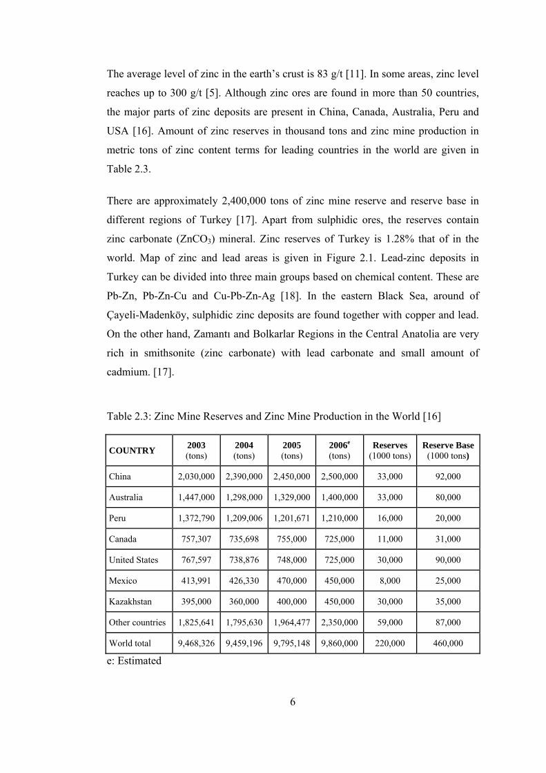
The average level of zinc in the earth’s crust is 83 g/t [11]. In some areas, zinc level
reaches up to 300 g/t [5]. Although zinc ores are found in more than 50 countries,
the major parts of zinc deposits are present in China, Canada, Australia, Peru and
USA [16]. Amount of zinc reserves in thousand tons and zinc mine production in
metric tons of zinc content terms for leading countries in the world are given in
Table 2.3.
There are approximately 2,400,000 tons of zinc mine reserve and reserve base in
different regions of Turkey [17]. Apart from sulphidic ores, the reserves contain
zinc carbonate (ZnCO3) mineral. Zinc reserves of Turkey is 1.28% that of in the
world. Map of zinc and lead areas is given in Figure 2.1. Lead-zinc deposits in
Turkey can be divided into three main groups based on chemical content. These are
Pb-Zn, Pb-Zn-Cu and Cu-Pb-Zn-Ag [18]. In the eastern Black Sea, around of
Çayeli-Madenköy, sulphidic zinc deposits are found together with copper and lead.
On the other hand, Zamantı and Bolkarlar Regions in the Central Anatolia are very
rich in smithsonite (zinc carbonate) with lead carbonate and small amount of
cadmium. [17].
Table 2.3: Zinc Mine Reserves and Zinc Mine Production in the World [16]
COUNTRY 2003 (tons)
2004 (tons)
2005 (tons)
2006e
(tons) Reserves
(1000 tons) Reserve Base
(1000 tons)
China 2,030,000 2,390,000 2,450,000 2,500,000 33,000 92,000
Australia 1,447,000 1,298,000 1,329,000 1,400,000 33,000 80,000
Peru 1,372,790 1,209,006 1,201,671 1,210,000 16,000 20,000
Canada 757,307 735,698 755,000 725,000 11,000 31,000
United States 767,597 738,876 748,000 725,000 30,000 90,000
Mexico 413,991 426,330 470,000 450,000 8,000 25,000
Kazakhstan 395,000 360,000 400,000 450,000 30,000 35,000
Other countries 1,825,641 1,795,630 1,964,477 2,350,000 59,000 87,000
World total 9,468,326 9,459,196 9,795,148 9,860,000 220,000 460,000
e: Estimated
7
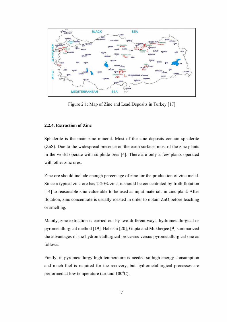
Figure 2.1: Map of Zinc and Lead Deposits in Turkey [17] 2.2.4. Extraction of Zinc
Sphalerite is the main zinc mineral. Most of the zinc deposits contain sphalerite
(ZnS). Due to the widespread presence on the earth surface, most of the zinc plants
in the world operate with sulphide ores [4]. There are only a few plants operated
with other zinc ores.
Zinc ore should include enough percentage of zinc for the production of zinc metal.
Since a typical zinc ore has 2-20% zinc, it should be concentrated by froth flotation
[14] to reasonable zinc value able to be used as input materials in zinc plant. After
flotation, zinc concentrate is usually roasted in order to obtain ZnO before leaching
or smelting.
Mainly, zinc extraction is carried out by two different ways, hydrometallurgical or
pyrometallurgical method [19]. Habashi [20], Gupta and Mukherjee [9] summarized
the advantages of the hydrometallurgical processes versus pyrometallurgical one as
follows:
Firstly, in pyrometallurgy high temperature is needed so high energy consumption
and much fuel is required for the recovery, but hydrometallurgical processes are
performed at low temperature (around 100oC).
8
Another important point is the formation of SO2 in pyrometallurgical ones. If SO2 is
not enough to make H2SO4, then its disposal is a very big problem. Although extra
energy is required to treat low grade ores due to presence of high amount of gangue
minerals in the pyrometallurgical method, this problem could be eliminated by
using a selective leachant in the hydrometallurgical ones. Lastly, hydrometallurgical
operations are performed in small scale and need lower capital investment than
those of pyrometallurgical.
2.2.4.1. Pyrometallurgical Methods
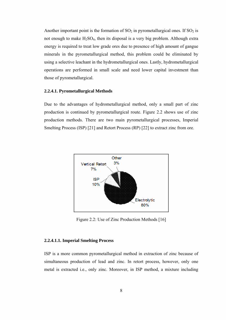
Due to the advantages of hydrometallurgical method, only a small part of zinc
production is continued by pyrometallurgical route. Figure 2.2 shows use of zinc
production methods. There are two main pyrometallurgical processes, Imperial
Smelting Process (ISP) [21] and Retort Process (RP) [22] to extract zinc from ore.
Figure 2.2: Use of Zinc Production Methods [16]
2.2.4.1.1. Imperial Smelting Process
ISP is a more common pyrometallurgical method in extraction of zinc because of
simultaneous production of lead and zinc. In retort process, however, only one
metal is extracted i.e., only zinc. Moreover, in ISP method, a mixture including

9
Zn-Pb sinter is charged to furnace and lead is tapped conventionally from the
bottom, on the other hand, vapor zinc is condensed in metallic form.
Zinc and lead metal are produced by reducing their oxides with carbon or
carbonaceous materials in imperial smelting furnace which is like an iron blast
furnace. Preheated charge materials are added to the furnace from the top. The
charge to the blast furnace is lump sinter and coke, the coke burning in the lower
part of the shaft and the heat from this and the carbon monoxide gas produced
providing the means to reduce the zinc and lead oxides to metallic zinc and lead.
While zinc evaporates due to its lower boiling point, lead goes to the bottom of the
furnace together with copper, silver and other metals. Zinc fume should be
condensed as soon as possible. Otherwise, it will be converted to zinc oxide.
Due to the special relationship between lead and zinc, by cooling the lead, crude
zinc is released and is separated, and the lead returns to the “condensing” process
for another cycle of dissolving and then releasing more zinc.
2.2.4.1.2. Retort Process
Although there are two types of zinc retort as vertical and horizontal, today; mainly
vertical retort is used to extract zinc. This is because of the fact that vertical retort
enables continuous operation and has larger production capacity. Main step in
vertical retort is to reduce ZnO by coke and to obtain Zn fume according to reaction
(2.1).
ZnO(s) + C(g) = Zn(g) + CO(g) ΔHo = 238,368 j/mole (2.1)
Since this reaction is endothermic, heat must be supplied up to required
temperature, 1300oC. As the reaction proceeds, zinc metal evaporates and zinc
fumes start to form as a reaction product. At the end of this process, condensed zinc
is obtained and casted as ingots with high recovery.

10
2.2.4.2. Hydrometallurgical Methods
In the world, over 90% of zinc production is from the primary sulphide ores
processed by Roast – Leach – Electrowinning route, but in Turkey, zinc ores are
treated in Waelz – Leach – Electrowinning sequence at Çinkur due to the fact that
reserves contain zinc carbonate (ZnCO3). As a result, hydrometallurgical extraction
of zinc can be summarized in two subsections for sulphidic ores and carbonated
ores.
2.2.4.2.1. Production of Zinc from Sulphidic Ores
Zinc is generally produced from primary sulphide ores. Hydrometallurgical zinc
extraction for sulphidic ores is operated by either conventional [21] or pressure
leaching [9] methods.
i) Conventional Leaching
Zinc concentrate obtained after flotation can be treated by leaching in batch or
continuous processes. Figure 2.3 shows the flowsheet for a simple electrolytic zinc
process called as “single leaching”. For sulphide type zinc concentrate, roasting is
the first step in this process. In roasting, ZnS reacts with oxygen according to
reaction (2.2). At the end of reaction zinc calcine (ZnO) is obtained and released
SO2 is sent to acid plant to produce sulphuric acid.
2ZnS + 3O2 = 2ZnO + 2SO2 (2.2)
During leaching, calcine is added to the spent electrolyte up to achieving the
minimum acid concentration to be able to dissolve zinc. In order to remove iron and
other impurities, pulp is neutralized with lime. In acid leaching, ZnO is converted to
the water soluble ZnSO4 according to reaction (2.3). After filtration pregnant
solution is obtained. This impure solution is then purified by adding scrap or zinc
dust, which precipitates the dissolve impurity metals by cementation. When the
solution leaves the purification section, it passes to the electrolytic tank house to
obtain high purity metallic zinc. In this step, reaction (2.4) given below takes place.

11
ZnO + H2SO4 = Zn2+ + SO42- + H2O (2.3)
Zn2+ + H2O = Zn0 + 1/2O2 + 2H+ (2.4)
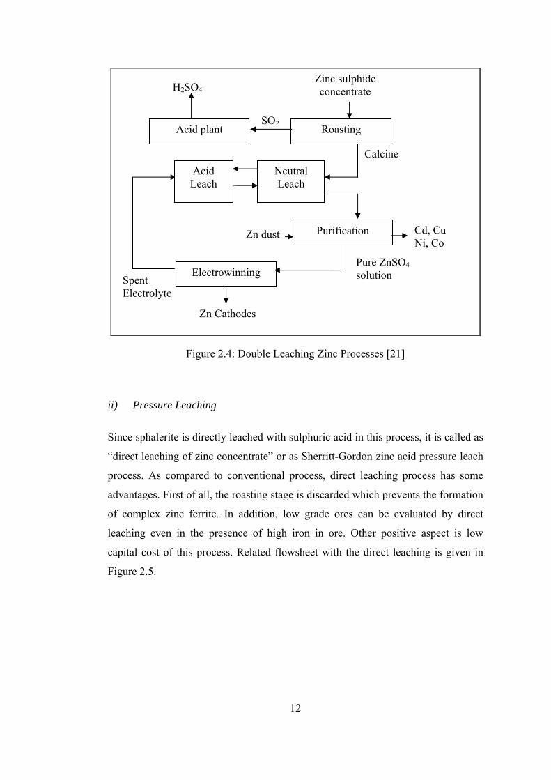
Figure 2.3: The Basic Flowsheet of Electrolytic Zinc Process [21] Depending on technological improvements, “double leaching” process, shown in
Figure 2.4, is developed. Mainly, this process resembles to single leaching, but it
has two leaching steps. In first stage, excess calcine is added until all the acid in the
electrolyte is consumed, in the meantime iron and other impurities are precipitated.
Second leaching stage is done by low acid solution. After that solution comes back
to first leach step and leach residue is discarded. Most of the electrolytic zinc plants
operate by using this process.
Zinc ore
Cd
Residue washing
Zn Cathodes
Electrowinning
Filtration
Purification
Neutralization
Spent Electrolyte
Make-up acid
Grinding and Classifying
ZnSO4 precipitation
Zn Dust
Residue
Leaching Limestone
12
Figure 2.4: Double Leaching Zinc Processes [21] ii) Pressure Leaching
Since sphalerite is directly leached with sulphuric acid in this process, it is called as
“direct leaching of zinc concentrate” or as Sherritt-Gordon zinc acid pressure leach
process. As compared to conventional process, direct leaching process has some
advantages. First of all, the roasting stage is discarded which prevents the formation
of complex zinc ferrite. In addition, low grade ores can be evaluated by direct
leaching even in the presence of high iron in ore. Other positive aspect is low
capital cost of this process. Related flowsheet with the direct leaching is given in
Figure 2.5.
Zinc sulphide concentrate
Cd, Cu Ni, Co
Zn Cathodes
Electrowinning
Purification
Neutral Leach
Spent Electrolyte
Calcine
Zn dust
Acid Leach
Roasting
Pure ZnSO4 solution
Acid plant SO2
H2SO4

13
Figure 2.5: Zinc Acid Pressure Leach Process [9] By using this process, any valuable metal can be obtained with various leachants. In
Figure 2.5, the required procedure is given for the recovery of zinc from concentrate
by using sulphuric acid as leachant. Concentrate should be finely ground to - 44
microns so that all particles react with sulphuric acid. Overall reaction (2.5) that
occurs in autoclaves is as follows:
ZnS + 1/2O2 + H2SO4 = ZnSO4 + S0 + H2O (2.5)
After leaching, leach liquor is sent to iron removal process and then purification
stage. Finally, zinc metal is obtained via electrowinning and spent electrolyte
returns to first stage. For typical pressure leaching maximum temperature should be
lower than 150oC and minimum oxygen partial pressure should be higher than 2
bar. By the use of these conditions, over 97% zinc extraction can be obtained.
Pressure Leaching
L/S Separation
Flotation
PbSO4 Separation
Electrowinning
Purification
Iron Removal
Liquor
Sulphur Separation
So Tailings PbSO4 Iron Cd, Cu Residue
Zn Cathodes
Zinc Sulphide Concentrate
O2
SolidsAir, CaCO3
Zn dust
ZnSSpent Electrolyte

14
2.2.4.2.2. Production of Zinc from Carbonated Ores
As mentioned before, in Turkey zinc reserves contain high amounts of smithsonite
(ZnCO3). Carbonate ores are very difficult to concentrate by flotation or other
mineral processing techniques. Therefore, these ores need a pyrometallurgical
pretreatment to be able to convert ZnCO3 to ZnO. Waelz kiln technology [23] has
been used for this pretreatment. Actually, Waelz process is designed for the
treatment of low grade and complex ores and it is applicable to all ores containing
zinc, lead, cadmium, etc.
Average length of Waelz furnace and interior diameter is 70 m and 4.3 m,
respectively. Waelz furnace feeds crushed ore and calculated amount of suitable
reducing agent, coke or coal. In the kiln, a long period reaction occurs between the
charge and reducing agents. Moreover, this enables complete decomposition of all
zinc compounds. In such a strong reducing atmosphere, together with the effect of
heating, metals in the charge are volatilized, and then these metallic vapors are
oxidized in kiln. Reduction of zinc oxide consumes much heat which is supplied by
oxidation of zinc vapor. All these events occur between 900 and 1300oC. At the end
of Waelz process, oxidized metals (ZnO, PbO, CdO) called as waelz oxide are
obtained. After densifying stage which requires removing volatile elements like Cl
and F, the production line resembles to other leaching processes explained above as
shown in Figure 2.6.

15
Figure 2.6: Electrolytic Zinc Production from Smithsonite Ore [3] 2.2.5. Applications of Zinc
Zinc is an important base metal required for various applications in metallurgical,
chemical and textile industries. As shown in Figure 2.7, the main application for
zinc is galvanizing which accounts for about 49% of worldwide zinc use. In order to
protect steel against corrosion, the most effective and economical way is zinc
coating, called galvanizing. Compared to the other materials, galvanized steel has
lots of advantages such as corrosion resistance, high strength, light weight and low
cost. Due to all of these properties galvanized steel is used in various applications
from automobiles to commercial and industrial constructions.
Zn Cathode
ZnCO3 Ore
Waelz Kiln
Densifying Kiln
Electrowinning
Filtration
Purification Zn Dust
H2SO4 Leaching
Leaching Residue
Discarded Spent Electrolyte
ZnSO4 Solution
Waelz oxide (ZnO)

16
In addition, zinc alloys are the other application areas. Zinc casting alloys are used
in mechanical parts due to their special high hardness, self lubricating properties,
and dimensional stability and so on. Since zinc has excellent thermal and electrical
conductivity, casting alloys also can be used for electrical components and heating
equipments. ZAMAK and ZA alloys are the basic zinc casting alloys. ZAMAK
includes about 4% Al, which gives good strength and excellent die castability.
Therefore, most of the zinc die castings are produced with ZAMAK alloys.
Figure 2.7: End Uses of Zinc [7] Brass is another material in the field of zinc applications. It includes copper and
zinc ranging from %10 to %50 Zn. Zinc as brass is mainly used in decorative
objects, door handles and interior design materials.
Zinc compounds have several applications in various industries. For example they
are used in alkaline batteries and dry batteries as well as in purification stage as
cement agent. Main zinc compound is zinc oxide used in the manufacture of paints,
pharmaceuticals, soap, textiles, electrical equipment and many other application
products.
In the 20th Century, except for mentioned above, zinc plays very important role in
many of the major inventions from transistors to lasers, satellites to circuit boards,
17
photocopiers to fuel cells, and zinc is really among the most versatile and essential
materials known to mankind [1-5, 15, 16].
2.3. Lead
2.3.1. History
Lead is a well-known metal and has been used by mankind for thousands of years
due to its easy extraction and smelting properties. The oldest lead piece is in the
British Museum and dates from 3800 B.C. Metallic lead is known to be produced
by the Chinese about 3000 B.C. Lead was used for plumbing by the Romans and
used for lining of tea chest by the Chinese. It was also utilized by Egyptians in
glazing pottery. Most of the oldest applications are still in use. Lead’s symbol Pb
comes from its Latin meaning “plumbum” which means soft metal.
In the early 1700s, the lead foundries developed in Great-Britain, and after a short
time first lead production started in the U.S.A. In the 1860s, new developments of
the lead technology greatly lowered production costs and increased productivity
within the lead industry [1, 5, 12, 23, 24].
2.3.2. Properties
Lead, represented by Pb, has atomic number of 82 and its color is bluish-white.
Natural lead has four stable isotopes. Pure lead has low mechanical strength. It is
also extremely soft and malleable. In addition, lead is a dense and ductile metal.
Atomic weight of lead is 207.2. It shows high resistance to corrosion but poor
electrical conductivity. Since lead is a heavy metal, it is hazardous for human health
and environment. The main properties of lead are summarized in Table 2.4 [1, 3,
24].
18
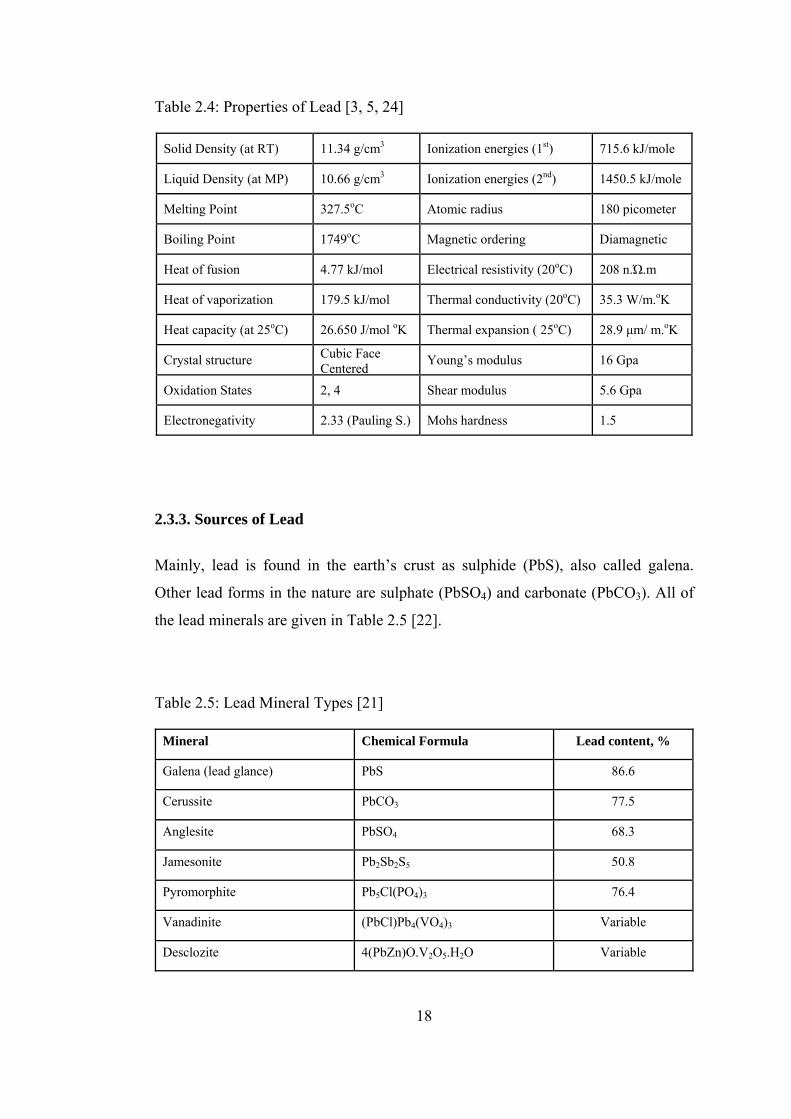
Table 2.4: Properties of Lead [3, 5, 24]
Solid Density (at RT) 11.34 g/cm3 Ionization energies (1st) 715.6 kJ/mole
Liquid Density (at MP) 10.66 g/cm3 Ionization energies (2nd) 1450.5 kJ/mole
Melting Point 327.5oC Atomic radius 180 picometer
Boiling Point 1749oC Magnetic ordering Diamagnetic
Heat of fusion 4.77 kJ/mol Electrical resistivity (20oC) 208 n.Ώ.m
Heat of vaporization 179.5 kJ/mol Thermal conductivity (20oC) 35.3 W/m.oK
Heat capacity (at 25oC) 26.650 J/mol oK Thermal expansion ( 25oC) 28.9 μm/ m.oK
Crystal structure Cubic Face Centered Young’s modulus 16 Gpa
Oxidation States 2, 4 Shear modulus 5.6 Gpa
Electronegativity 2.33 (Pauling S.) Mohs hardness 1.5
2.3.3. Sources of Lead
Mainly, lead is found in the earth’s crust as sulphide (PbS), also called galena.
Other lead forms in the nature are sulphate (PbSO4) and carbonate (PbCO3). All of
the lead minerals are given in Table 2.5 [22].
Table 2.5: Lead Mineral Types [21]
Mineral Chemical Formula Lead content, %
Galena (lead glance) PbS 86.6
Cerussite PbCO3 77.5
Anglesite PbSO4 68.3
Jamesonite Pb2Sb2S5 50.8
Pyromorphite Pb5Cl(PO4)3 76.4
Vanadinite (PbCl)Pb4(VO4)3 Variable
Desclozite 4(PbZn)O.V2O5.H2O Variable
19
Galena including only a few grams silver per ton ore is widely dispersed in the
world [23]. The main sources are the U.S.A., China, Australia, Spain, Mexico, and
Germany. Depending on data given in ILZSG (International Lead and Zinc Study
Group), January 2007 [5] Asia is the leading world lead producer and consumer.
Lead production and reserves values in the world according to leading countries are
given Table 2.6.
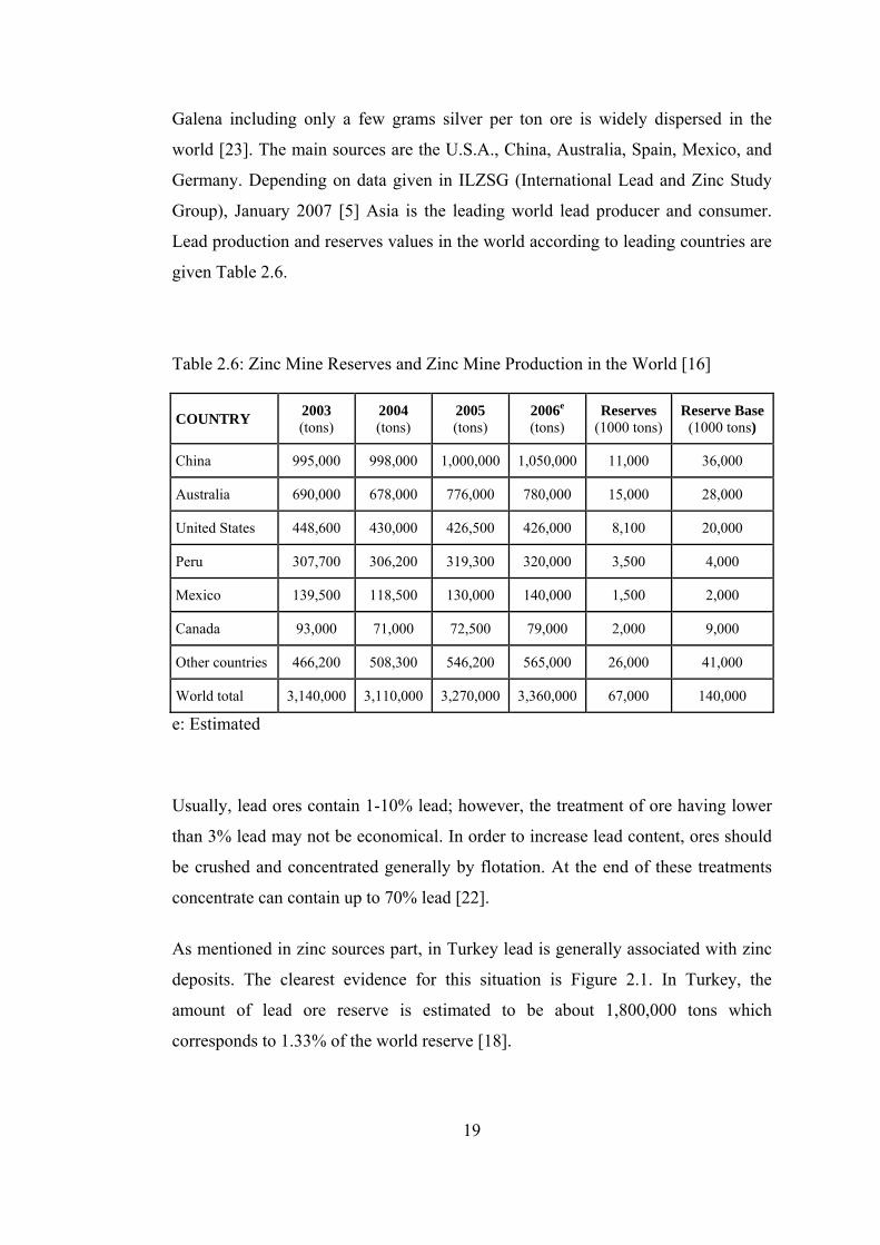
Table 2.6: Zinc Mine Reserves and Zinc Mine Production in the World [16]
COUNTRY 2003 (tons)
2004 (tons)
2005 (tons)
2006e
(tons) Reserves
(1000 tons) Reserve Base
(1000 tons)
China 995,000 998,000 1,000,000 1,050,000 11,000 36,000
Australia 690,000 678,000 776,000 780,000 15,000 28,000
United States 448,600 430,000 426,500 426,000 8,100 20,000
Peru 307,700 306,200 319,300 320,000 3,500 4,000
Mexico 139,500 118,500 130,000 140,000 1,500 2,000
Canada 93,000 71,000 72,500 79,000 2,000 9,000
Other countries 466,200 508,300 546,200 565,000 26,000 41,000
World total 3,140,000 3,110,000 3,270,000 3,360,000 67,000 140,000
e: Estimated Usually, lead ores contain 1-10% lead; however, the treatment of ore having lower
than 3% lead may not be economical. In order to increase lead content, ores should
be crushed and concentrated generally by flotation. At the end of these treatments
concentrate can contain up to 70% lead [22].
As mentioned in zinc sources part, in Turkey lead is generally associated with zinc
deposits. The clearest evidence for this situation is Figure 2.1. In Turkey, the
amount of lead ore reserve is estimated to be about 1,800,000 tons which
corresponds to 1.33% of the world reserve [18].
20
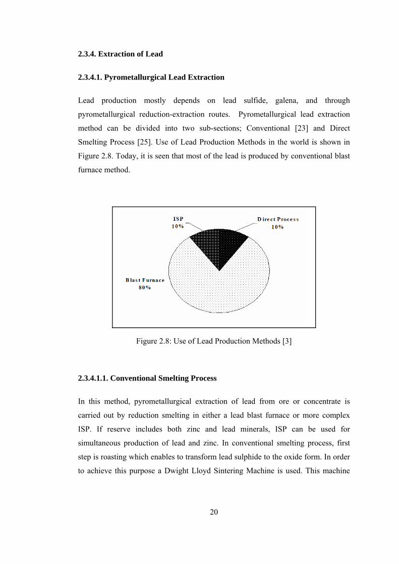
2.3.4. Extraction of Lead
2.3.4.1. Pyrometallurgical Lead Extraction
Lead production mostly depends on lead sulfide, galena, and through
pyrometallurgical reduction-extraction routes. Pyrometallurgical lead extraction
method can be divided into two sub-sections; Conventional [23] and Direct
Smelting Process [25]. Use of Lead Production Methods in the world is shown in
Figure 2.8. Today, it is seen that most of the lead is produced by conventional blast
furnace method.
Figure 2.8: Use of Lead Production Methods [3] 2.3.4.1.1. Conventional Smelting Process
In this method, pyrometallurgical extraction of lead from ore or concentrate is
carried out by reduction smelting in either a lead blast furnace or more complex
ISP. If reserve includes both zinc and lead minerals, ISP can be used for
simultaneous production of lead and zinc. In conventional smelting process, first
step is roasting which enables to transform lead sulphide to the oxide form. In order
to achieve this purpose a Dwight Lloyd Sintering Machine is used. This machine
21
supplies feed suitable for the blast furnace. Feed includes lead sulphide concentrate,
returned sintering fines and limestone flux.
Lead blast furnace requires high amount of heat in order to reduce lead oxide. Most
of the required heat is supplied by the combustion of carbon. After combustion of
carbon, carbon monoxide is formed. Beginning at a temperature of about 400oC, the
CO produced lower down in the furnace reduces the lead oxide according to
reaction (2.6) thus liberated lead trickles down over the particles of undecomposed
ore, absorbing precious metals as well as a part of arsenic, copper and antimony.
PbO + CO = Pb + CO2 (2.6)
At about 600-700oC, iron oxide in the charge is reduced by CO and this iron
decomposes lead sulphide and oxide. Lead is also formed by direct reduction of
carbon and by the reactions between lead sulphide and oxide as seen in reactions
(2.7-2.9)
2PbO + C = 2Pb + CO2 (2.7)
2PbO + PbS = 3Pb + SO2 (2.8)
PbSO4 + PbS = 2Pb + 2SO2 (2.9)
Finally, metal and slag is completely liquid at temperatures higher than 1000oC, and
lead is tapped from the furnace.
2.3.4.1.2. Direct Smelting Processes
Due to environmental problems and inefficient energy usage of the conventional
processes, researchers studied to develop more economical and less pollution
processes for the production of lead. Some of them aimed at devising processes in
which lead is converted directly from the sulphide to metal. Main advantage of
these processes is that PbS transforms to PbO without initial step. Consequently,
several direct smelting processes, Kivcet, QSL (Queneau-Schuhmann-Lurgi),
Ausmelt and Outokumpu, have been developed.

22
i) Kivcet
Kivcet® method based on the Soviet technology is a direct smelting process. Since
simultaneous production of zinc and lead is possible in this method, it is suitable for
complex ores with high zinc contents. After grinding and drying, sulphide
concentrate and flux are injected to furnace with technically pure oxygen. So, the
roasting and smelting stages are carried out, simultaneously. Liquid metal and slag
pass from the smelting shaft into electric furnace to reduce oxides to metal by the
addition of coke. At last, metallic materials are tapped from the furnace. Zinc and
lead can be recovered at about 85% and 99% efficiency, respectively.
Kivcet® method has some advantages;
- Handling of dried lead-bearing charge and hence the formation of dust is
kept to a minimum,
- Having smaller process off-gas volumes due to using pure oxygen instead of
air,
- SO2 concentration is high to produce sulphuric acid [3].
ii) QSL®
QSL (Queneau – Schuhmann – Lurgi) process is a continuous process. In this
process, sulphide concentrate, return flue dust and flux are continuously mixed with
a little water and compacted into pellets which are dropped directly into the
oxidation zone of the reactor. The pellets dissolve rapidly in the resulting molten
bath and are partially oxidized lead to lead oxide by submerged injection of oxygen.
Oxidation is autogenous at the operating temperature of 950 - 1000OC and the
evolution of lead fume is low. At the end of process metallic lead is tapped
continuously with a little copper and silver. Slag containing lead oxide and other
metal oxides is also continuously discharged in opposite direction of the matte.
Lead content in the slag is about 2%.
QSL process has the same advantages with Kivcet, i.e., low off gas volume and
high SO2 concentration. There is one extra advantage; QSL process is very suitable

23
for the environment. Since all raw materials are handled in a moist state there is
little opportunity for dust evolution [3, 25].
iii) Ausmelt®
The Ausmelt process originated in Australia is developed by using Sirosmelt® lance
technology. The lsasmelt (Ausmelt) process for lead is a fully continuous two stage
process which is based on gas injection into melts via a top entry submerged
Sirosmelt lance. Submerged injection produces turbulent baths in which high
intensity smelting or reduction reactions may occur. In the first stage of the process,
lead concentrate is added directly to a molten slag bath and is oxidized by air
injected down the lance. Simultaneously, the high lead slag from this furnace is
continuously transferred down a launder to a second furnace and reduced with coal.
The crude lead product and discard slag are tapped continuously from the reduction
furnace through a single taphole and separated in a conventional forehearth. This
process provides several advantages i.e. compact vessels, durable submerged
lances, good hygiene, simple control and operation and so on. [3]
iv) Outokumpu®
This process was developed in Finland to treat copper concentrates and has become
standard technology in that field. It is a flash or suspension smelting process that
uses technical oxygen to burn sulphur and fuel. Drying, flash smelting, slag
cleaning and gas handling are the main parts of this process. After mixing, lead
concentrate and fluxes are dried and fed to flash smelting. In flash furnace
concentrate is oxidized and then smelted directly into the lead bullion and slag.
Quality of lead bullion depends on degree of oxidation. Process needs a small gas
cleaning step owing to low gas volume and high concentration of SO2 which is
suitable for sulphuric acid manufacture [25].
2.3.4.2. Hydrometallurgical Lead Extraction
In order to benefit from advantages of hydrometallurgical method many
researchers studied hydrometallurgical treatment of primary or secondary sources of
24
lead and a few processes have been developed. However, none of them is applicable
and economic compared with pyrometallurgical processes. Several facts have
contributed to limit its application. The most important fact is that pyrometallurgical
processes are simpler and cheaper and also highly pure product can be produced by
using this method. In addition, suitable reagent has not been found to dissolve
directly sulphide ores. Therefore, hydrometallurgical lead extraction has not been
practiced industrially on a large scale.
Nevertheless, direct leaching of lead sulphide was tested at pilot plant scale.
Leaching of lead sulphide concentrates usually occurs in the presence of a
concentrated solution of NaCl. A complex lead chloride (PbCl42-) is formed
according to reaction (2.10).
PbS + 2Fe3+ + 4Cl- = PbCl42- + 2Fe2+ + S0 (2.10)
In order to separate the gangue minerals, hot filtration step is needed. After
filtration, solution is cooled to crystallize pure PbCl2 which is then separated and
sent to fused salt electrolysis step to recover lead and chlorine [20].
Other possible processes required a pretreatment step. Converting sulphide ores to
the sulphate by roasting process with sulphuric acid at low temperature (400-
500oC), soluble compound (PbSO4) can be obtained and dissolved by a saturated
sodium chloride solution. At the end of this process, lead chloride (PbCl2) produced
is separated and electrolyzed in the fused state to obtained lead [21].
2.3.5. Applications of Lead
Lead is widely used in various industries both as the metal and as its chemical
compounds such as lead chromate, lead molybdate, tetraethyl lead and tetra
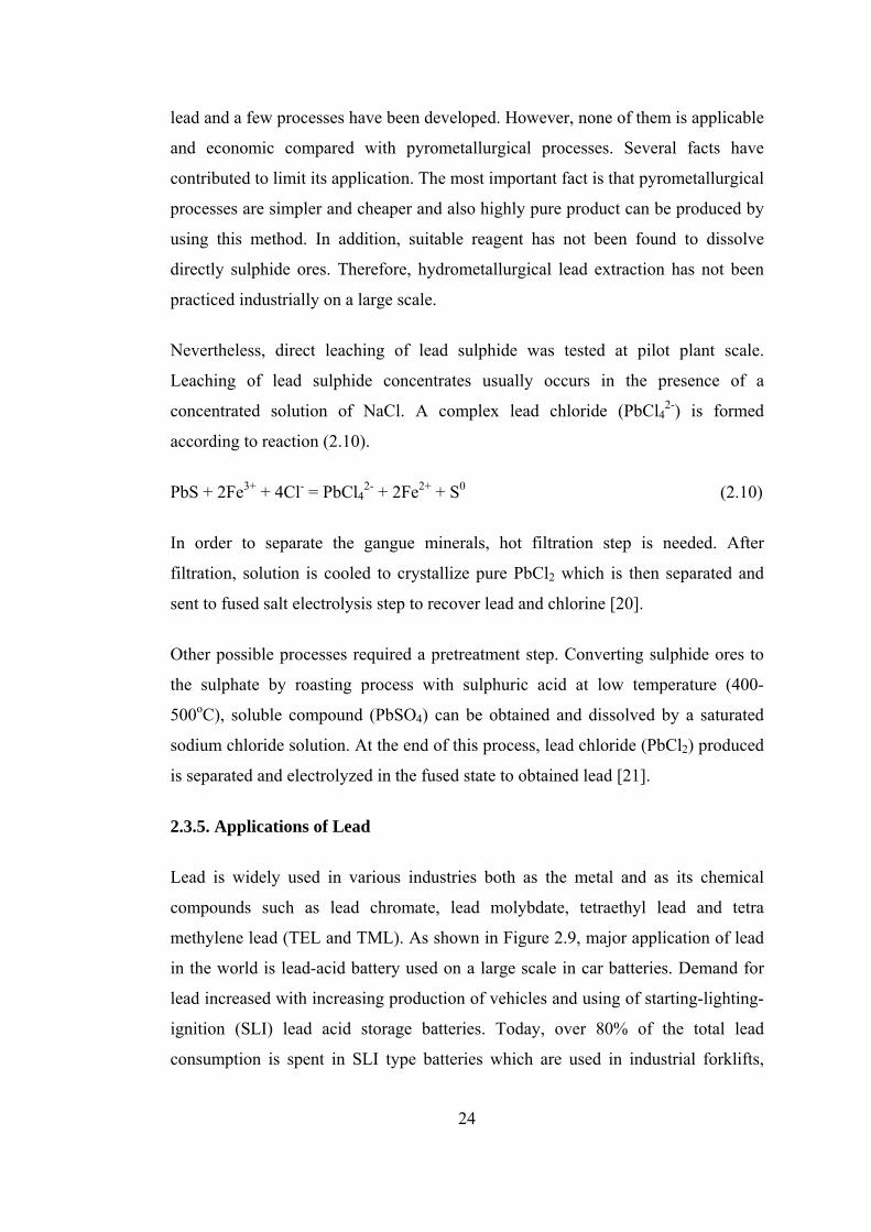
methylene lead (TEL and TML). As shown in Figure 2.9, major application of lead
in the world is lead-acid battery used on a large scale in car batteries. Demand for
lead increased with increasing production of vehicles and using of starting-lighting-
ignition (SLI) lead acid storage batteries. Today, over 80% of the total lead
consumption is spent in SLI type batteries which are used in industrial forklifts,
25
airport ground equipment, mining equipment, as well as stationary sources of power
in uninterruptible power systems (UPS) for hospitals, computer and
telecommunications networks.
For example, in the USA, 88% of the total lead consumption is spent by lead-acid
storage batteries. Other uses are ammunition (3%), oxides in glass and ceramics
(3%), casting metals (2%), and sheet lead (1%). The remainder was consumed in
solders, bearing metals, brass and bronze bullets, covering for cable, and extruded
products.
Another important application of lead is radiation shielding in high energy radiation
fields. Due to its high density and high atomic number, lead is used in shielding
applications. Moreover, lead in powder form is used as a material for protective
clothing in plastic and rubber sheeting.
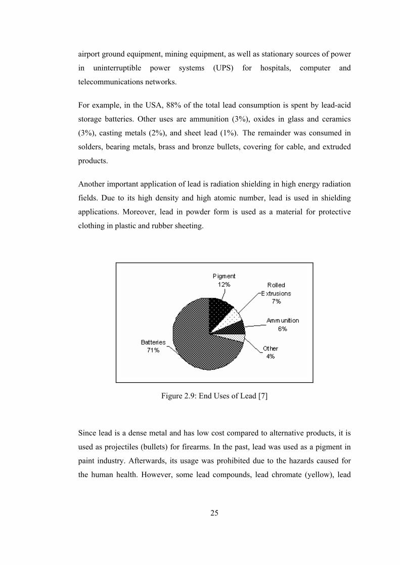
Figure 2.9: End Uses of Lead [7] Since lead is a dense metal and has low cost compared to alternative products, it is
used as projectiles (bullets) for firearms. In the past, lead was used as a pigment in
paint industry. Afterwards, its usage was prohibited due to the hazards caused for
the human health. However, some lead compounds, lead chromate (yellow), lead

26
molybdate (red) are still in use in road markings and plastics, respectively. In
addition, lead as coloring element gives white and red color to ceramic glazes.
Other lead compounds are tetraethyl and tetra methylene lead (TEL and TML).
These compounds are used in gasoline to increase octane rating and so provide the
grade of gasoline required for the efficient operation. In order to extend the
temperature range for rigid and plasticized PVC, tri or tetra basic lead sulphate is
used [1, 3, 16, 24].
2.4. Secondary Resources of Zinc and Lead
In the world, zinc and lead are generally produced from primary sulphide or other
ores. However, as stated before, increasing demand of metals has necessitated
recovering metals from secondary resources or extraction of metals from low-grade
ores. In other words, secondary resources have become a very important source for
zinc and lead, like other metals, due to depletion of high grade ores and increasing
demand of these metals [2, 19].
Today, in the world, over 70% of zinc is produced from zinc mines and remaining
from industrial wastes [4]. There are various secondary zinc wastes discarded in
different metallurgical plants. For instance, zinc ash, flux skimming or zinc dross
come from galvanizing industry and leach residue comes from zinc plants from
which zinc is produced via leaching methods. Moreover, considerable amount of
recoverable zinc is present in blast furnace and electric arc furnace dusts. These zinc
wastes have different chemical compositions as seen from Table 2.7 [2].

27
Table 2.7: List of Secondary Zinc Resources [2]
Types Composition in wt %
Zinc Ash 60-85 Zn, 0.3-2 Pb, 0.2-1.5 Fe, 2-12 Cl
Flux Skimming 5.6 metallic Zn, 48.1 ZnCl2, 27.4 ZnO, 3.2 Al Galvanizing Industry
Zinc Dross 96 Zn, 4 Fe
Electric Arc Furnace (AEF) Dust 19.4 Zn, 24.6 Fe, 4.5 Pb, 0.42 Cu, 1.4 Si, 6.8 Cl
Blast Furnace (BF) Flue Dust Major component Fe, also contains Zn, Si, Mg
Leaching Process Leach Residue 10-12 Zn, 15-17 Pb, 6-7 Fe, 8-10 CaO, 15-16 SiO2
On the other hand, lead is recovered from secondary resources which are based on
mainly lead-acid batteries, and low amount zinc plant residues (neutral leach
residue) and others. By the year 2000, more than 60 percent of the industry's
production came from recycled materials, primarily due to the large number of
scrapped lead batteries. Besides, in the last years recycling level of lead reached up
to 83% of total consumption in USA [16].
2.5. Previous Studies on Leach Residues
2.5.1. Previous Studies on Recovery of Zinc and Lead from Çinkur Leach
Residue
In this part, the previous studies about Çinkur leach residue will be given in
chronological order. A number of studies have been carried out by researchers
about Çinkur leach residue obtained from its discarded stock area. However, none
of them have developed a feasible or applicable process for this residue.
First study about this topic was performed by the Mountain State Research and
Development Co. [26] in 1977. This company conducted several heavy media
separation tests on zinc-lead ores and leach residues by using flotation techniques.
However, no success was achieved in producing a lead-zinc concentrate or in
separating the lead and zinc contents of the leach residues. According to their

28
results, at least three factors were adversely influencing the recovery of the zinc in
metallurgical treatment. These were:
- The smithsonite was intergrown with impure calcite,
- The hemimorphite which was a silicate compound in the ore did not float along
with smithsonite,
- Some particles of these minerals were impregnated with iron oxide,
In 1979, a report was presented by SNC Services Ltd. [27] on the applicability of
potential residue upgrading methods of both beneficiation and hydrometallurgical
processing. In this report, it was recommended that Vieille Montagne beneficiation
method could be applicable for Çinkur leach residue. In addition, three iron removal
processes (Jarosite, Goethite and Hematite) were reviewed in detail and jarosite
process was suggested due to the lower capital cost.
Kahraman et. al. [28] investigated the optimum sulphuric acid leaching conditions
to reach maximum zinc recovery from Çinkur leach residue. After all trials, acid
leaching conditions were determined as 5 M acid concentration, 40oC leaching
temperature, 1/10 solid to liquid ratio and 4 h reaction duration. At these conditions
47% Zn recovery was achieved at the same time 53% Fe was dissolved. It was
stated that Fe dissolution sharply increased with the increasing reaction temperature
so the optimum leaching temperature was chosen as 40oC.
In addition to acid leaching process, chloride based leaching conditions were also
investigated for Çinkur leach residue. Complex chloride solution was used to
dissolve valuable metals in the residue. For this purpose, 1 M FeCl3, 200 g/l NaCl
and 10 g/l HCl were mixed and used for the residue at 100oC in 2 h. It was reported
that 52% Zn and 87% Pb were recovered by applying chloride leaching.
Doğan et. al. [29] carried out some physical beneficiation methods to enrich zinc
and lead in the leach residue. Initially, mineralogical leach residue analyses were
done and it was found that leach residue was composed of PbSO4, CaSO4.2H2O,
ZnSO4.H2O, Fe2O3, ZnFe2O4, SiO2 and other minor complex silicate compounds. In
order to increase lead content in the leach residue, slime table, flotation and acid
29
leaching methods were used. By applying slime table method, lead content in the
residue was improved from 19.7% to 27.2% with 47% recovery. On the other hand,
in flotation method several reagents such as Na2S, xanthate, pine oil were tried to
increase lead content in the residue but lead in the final residue was never beyond
25.3%. Lastly, acid leaching method was applied to the leaching residue and the
lead content in the final residue was about 31% after removal of zinc and iron in the
residue.
Another study about metallurgical evaluation of Çinkur neutral leach residue was
performed by the researchers of Istanbul Technical University [30]. Firstly, they
have leached the residue with water in order to determine water soluble compounds.
It was found that the residue contained notable amount of zinc and cadmium as
ZnSO4 and CdSO4. After that, acid leaching process was applied at different
temperatures for various times in order to obtain maximum Zn recovery from the
residue. By acid leaching practice, about 60% Zn recovery was obtained but 43%
Fe was also dissolved. In order to remove iron in solution, jarosite process was
suggested. In addition, it was considered that lead in the residue obtained after acid
leaching could be enriched by using flotation method. However, this attempt was
not successful.
Addemir [31] studied the metallurgical evaluation of Çinkur neutral leach residue
by baking in concentrated sulphuric acid. This alternative study had two main steps.
One was baking step starting from 150-250oC after mixing residue and sulphuric
acid at predefined ratio. In this step, compounds zinc ferrite and iron oxide in the
residue transformed to water soluble compounds zinc sulphate and iron sulphate. In
the second step, residue obtained in the first step was heated to 600-650oC in order
to convert Fe2(SO4)3 to Fe2O3. This baked cake was leached with water and over
90% zinc recovery was obtained. In addition, at the end of this process iron
dissolution was very low (around 7%) because it was obtained as hematite which is
not hazardous for the environment.
In 1992, a preliminary evaluation of pyrometallurgical processes was conducted by
Cominco Engineering Service Ltd. (CESL) [25] in order to select a

30
pyrometallurgical process for treatment of Çinkur leach residue and ores. Four lead
smelter processes namely Ausmelt, Kaldo, Kivcet and Outokumpu, for process
characteristics such as metallurgy, commercial application, operating
flexibility/versatility and simplicity were evaluated by CESL. After comparison of
these processes, Kaldo was chosen as the recommended process for Çinkur leach
residue and ores. However, this recommendation was never applied to treat either
Çinkur ores or leach residues.
Most recent study about Çinkur leach residue was done by Turan et al. [32] in 2004.
They have investigated zinc and lead recovery from zinc plant residue (ZPR) which
was discarded as a cake from a Waelz kiln processing zinc-lead carbonate ores.
Firstly, in order to recover zinc from residue, water leaching was performed at 25oC
for 60 min. with a pulp density of 20% solids after roasting with an equal weight
ratio of H2SO4/ZPR. They noted that roasting step after mixing ZPR with H2SO4
was needed to decompose the ferrite structure thus high zinc recovery could be
obtained and they stated that about 85% zinc recovery could be obtained after
roasting at 200oC for 30 minutes. Second step was carried out to recover lead from
the secondary leach residue. In this step, secondary leach residue obtained after the
first step was subjected to NaCl leaching. Their investigation showed that the
recovery of lead significantly depended on NaCl concentration and pulp density. At
the end of experiments, about 89% Pb was recovered in 200 g/l NaCl at 25oC in 10
minutes at a low pulp density (20 g/l). In addition, they recommended that lead
from the second stage leach solution could be recovered by Na2S precipitation in
order to obtain a rich PbS concentrate which is suitable for pyrometallurgical
treatment.
2.5.2. Previous Studies on Recovery of Zinc and Lead from Other Residues
There are a lot of recovery techniques of zinc and lead from secondary resources
especially leaching residues. Generally, for this purpose hydrometallurgical method
is the most convenient. In hydrometallurgical processes, different leachants are used
for the recovery of zinc and lead.

31
Jha et. al. [2] reviewed in an article about the hydrometallurgical zinc recovery from
industrial wastes. They described that various leachants could be used to recover
zinc from secondary resources. According to this review paper, in all of the
reagents, sulphuric acid is the best leachant to recover zinc from leach residues.
Others are based on chloride (HCl, CaCl2, etc.), ammonium (NH4CO3, NH4Cl, etc.)
and caustic soda (NaOH). Although some of them (sulphuric acid, ammonical
solutions) have found commercial use in plants, the remaining processes are not
applicable industrially due to insufficient recoveries or high costs.
As stated and approved by many researchers, sulphuric acid has been employed
mostly for the hydrometallurgical extraction of zinc from ores or secondary
resources since zinc oxide (ZnO) and zinc ferrite (ZnO.Fe2O3) being the most
important compounds are soluble in concentrated sulphuric acid. Actually, zinc
oxide can be dissolved even with dilute sulphuric acid but not zinc ferrite. Zinc
oxide and zinc ferrite react with sulphuric acid according to the following reactions
(2.11, 2.12) [9]:
ZnO + H2SO4 = ZnSO4 + H2O (2.11)
ZnO.Fe2O3 + 4H2SO4 = ZnSO4 + Fe2(SO4)3 + 4H2O (2.12)
According to Jha et. al., [2] the Warren Spring Laboratory in UK carried out
sulphuric acid leaching of EAF dust having 36% Zn as zinc ferrite and zinc oxide
and reached 85 to 90% Zn recovery at pH 2 and 80% Zn recovery at pH 3 to 4 at
90oC.
By using acidic leach process, the recovery of zinc from slag which contained
considerable amounts of zinc was investigated by Kurama and Göktepe [33]. In
order to increase the recovery, leaching tests were performed in two stages in dilute
and then concentrate sulphuric acid. Concentrated hot acid leaching step was
applied to dissolve zinc ferrite present in the slag. It was found that about 77% Zn
extraction could be achieved by atmospheric leaching.
As mentioned earlier, at hot acid leaching conditions, zinc ferrite dissolves and so
zinc and iron are present in the leach solution. Zinc ferrite is the main source of iron

32
which is an undesirable element in the leach solution. In the commercial flowsheet
for the zinc production during roasting stage, zinc ferrite forms at above 650oC
according to reaction (2.13) between zinc and iron oxides present in the concentrate.
ZnO + Fe2O3 = ZnO.Fe2O3 or (ZnFe2O4) (2.13)
Since zinc ferrite is insoluble under normal leaching conditions with dilute
sulphuric acid, its formation limits the zinc recovery of the processes. This is a
problem only in processes operated with dilute sulphuric acid leaching. It has long
been known that at the boiling point zinc ferrite dissolves in sulphuric acid. Zinc
sulphate solution obtained by dissolving zinc ferrite contains high amount of iron as
ferric sulphate which must be removed before electrolysis [34].
Iron is usually present in leach solutions and its elimination is a major operational
problem in zinc hydrometallurgy. The removal of iron from such solutions is
usually carried out by precipitation as jarosite, goethite or hematite.
The conventional jarosite process was developed and patented simultaneously by
three different companies in early 1960s. In jarosite process, iron is precipitated
from the hot acid leaching solution at elevated temperatures (95-97oC) in the
presence of mainly Na+ or NH4+ ions. Jarosites are complex basic iron sulphates,
and their formation is represented by the following reaction (2.14) [35]:
3Fe2(SO4)3 + M2SO4 + 12H2O = 2MFe3(SO4)2(OH)6 + 6H2SO4 (2.14)
where M represents any of the ions Na+, NH4+, H3O+, Li+, K+, 1/2Pb2+. According
to Acharya et. al., [36] efficiency of the cations for iron removal in jarosite process
was in the following order; Na+ > NH4+ > K+.
It was the first iron removal process and is still the most widely used process in the
zinc industry today due to the production of a filterable iron residue on a
commercial scale [37]. However, storage of the residue is a big problem since large
amounts of residues are produced, and so this process has become questionable on
environmental grounds [35].
33
The goethite process was developed by the Societe de la Viella Montagne in
Belgium, in 1968 [37]. This process is successfully practiced in the electrolytic zinc
industry. Iron is precipitated as goethite (FeO.OH) from an aqueous solution. This
can be accomplished by reducing all ferric ions to the ferrous state or by adding the
concentrated ferric solution to the precipitation tank at the same rate of goethite
precipitation. The goethite is precipitated by reaction (2.15):
Fe2(SO4)3 + 4H2O = 2FeO.OH + 3H2SO4 (2.15)
This reaction should be performed at 80–900C and pH 2–3. It is necessary to
neutralize the acid formed during the goethite precipitation. One advantage of
precipitating iron as goethite instead of jarosite is the low volume of the waste
goethite [35].
Another iron removal process called Hematite or Akita process was developed by
Dowa Mining Company, Japan. This process contains mainly four steps:
- Leaching the residue with spent electrolyte and SO2 gas,
- Precipitation of copper with H2S gas,
- Neutralization of excess H2SO4 with lime,
- Conversion of iron to ferric state with oxygen [34].
In the first step, zinc leach residue is leached with a mixture of the spent acid in an
autoclave operating at 95-100oC. After copper precipitation, solution is neutralized
with addition of lime. In the last stage, solution is heated to around 200oC in
titanium autoclaves and iron is precipitated as ferric oxide in oxygen atmosphere
(ρO2 > 5 bar). The hydrolysis of ferrous sulphate to hematite is represented by the
following reaction (2.16) [35]:
2FeSO4 + 1/2O2 + 2H2O = Fe2O3 + 2H2SO4 (2.16)
Hematite as a marketable material can be used in cement manufacture or pigments.
Moreover, a high purity hematite (totally free of the contaminants) can be utilized in
steel manufacture [38].

34
Apart from these three iron removal processes, some other processes have been
investigated by researchers but not all of them can be used industrially due to
various reasons essentially from economic point of view. Nonetheless, some (E.Z.
process, conversion process, paragoethite process etc.) have been applied on a
larger scale [34].
Although it is known that most important leachant is sulphuric acid in order to
dissolve zinc ferrite, different leachants were examined by some researchers.
Caustic soda (NaOH) is an example for these studies. Youcai and Stanforth [39]
cited that zinc ferrite can be extracted after being fused directly with NaOH pellets
and dissolved in an alkaline leaching solution. They studied with electric arc
furnace dust which included high amount of zinc ferrite. By using magnetic
separator, dust was separated into two fractions, and then magnetic fraction,
primarily zinc ferrite, was leached in 11 M NaOH solution for 4 hours at 95oC.
Other fraction, non-magnetic including mainly ZnO, was leached with 6 M NaOH
solution for 1.5 hour at 95oC. They stated that at the end of these trials, over 80% of
the total Zn and Pb recovery was obtained.
Youcai and Stanforth [40] studied caustic leaching about of EAF dusts and also
smithsonite containing Zn-Pb ores. They proposed that ores should be broken into
particles smaller than 0.1-0.5 mm and leached with 5 M NaOH solution at a 90-
95oC temperature for 1.5 h. After filtration, the leach solution was reacted with
sodium sulphide to separate lead as PbS and then sent to electrolysis process for the
production of metallic Zn. They reported that over 85% of both Zn and Pb could be
recovered at this leaching condition.
Another caustic soda leach technique was used by Xia and Pickles [41]. Unlike
above technique, firstly dust was roasted with caustic soda at low temperatures.
Therefore, zinc ferrite in the dust was converted into sodium zincate (Na2ZnO2) and
iron oxide (Fe2O3) as seen in reaction (2.17).
ZnFe2O4 + 2NaOH = Na2ZnO2 + Fe2O3 + H2O (2.17)

35
After caustic roasting at about 400-450oC, dilute caustic leaching process was
performed to recover zinc and lead. According to their results, about 95% Zn and
85% Pb were recovered and also the majority of iron oxide remained in the leach
residue.
Lin Min [10] also tried to separate zinc and lead from industry wastes by using
alkaline leaching. He used 5 M NaOH as the leaching reagent. After NaOH
leaching at 25oC for 42 hours, only about 53% Zn and over 70% Pb could be
recovered from the dust. Lead in the solution could be removed successively as lead
sulphide (PbS) by the addition of solid sodium sulphide. Lead sulphide could be
used directly in the lead smelters due to the presence of high amount lead content.
In addition to these processes, Blanco et. al. [42] studied the leaching behavior of
zinc residue when using ammonium carbonate – ammonia solution. They developed
an equation for the dissolution of zinc as a function of temperature, pH and solids
concentration. Considering the equation, the optimum leaching parameters to
achieve maximum zinc recovery should be as follows;
- Temperature as high as possible but less than boiling point of the solution.
- pH as high as possible. (Maximum pH limit 11 since ammonia solution was buffer
solution)
- Solids concentration used will determine the capacity of the process.
It was stated that the maximum zinc recovery that could be obtained was 95% for
zinc waste materials.
Chloride based processes were also used in hydrometallurgical processing of
secondary residues containing zinc. HCl is one of the reagents for chlorination
process. Nunez and Vinals [43] leached the residue containing zinc ferrite with
hydrochloric acid and obtained zinc chloride (ZnCl2). In addition, they investigated
kinetics of zinc ferrite dissolution in aqueous hydrochloric acid solutions.
Ammonium chloride solution has also been used for the recovery of zinc from
secondary resources. For this purpose, Ezinex process has been developed by

36
Engitec Implant. Olper et. al. [44] explained that this process was operated at 70-
80oC for 1 hour and main leaching reaction was between zinc oxide and ammonium
chloride in accordance with reaction (2.18)
ZnO + 2NH4Cl = Zn(NH3)2Cl2 + H2O (2.18)
For recovery of lead from zinc plant residue several methods have been developed.
For example, conversion of lead sulphate in residue to lead chloride (PbCl2) by
leaching with sodium chloride (NaCl) or lead hydroxide, (Pb(OH)2) by leaching
with sodium hydroxide (NaOH) or lead carbonate (PbCO3) by leaching with sodium
carbonate (Na2CO3) has been investigated in lead recovery. According to Abdollahi
et. al. [45] considering these three methods, NaCl (brine) can be selected as the
most suitable leachant due to the low cost of salt without requirement of additional
investment and any threat to the environment.
Raghavan et. al. [46] stated that sulphuric acid leaching was performed to dissolve
zinc and so lead will be enriched in the residue. The residue was treated with brine
(NaCl) solution to solubilise most of the lead. They have developed a
hydrometallurgical process convenient with this procedure. Firstly, they leached the
residue with sulphuric acid (200 g/l) at 85oC for 2 h and continued with brine
leaching, 300 g/l NaCl, for 30 min at pH 1.5-2. In addition, they tried to cement out
lead by using zinc, iron or aluminum. At the end of all these trials they recovered
around 90% Pb and 80% Zn.
In a more recent work reported by Raghavan et. al. [47], it was tried to transform
PbSO4 to PbS by using sodium sulphide (Na2S) and sodium chloride (NaCl). They
proposed two methods in order to produce high quality lead concentrate. First part
of the work was concerned with a double decomposition technique; to remove acid
soluble metals, the residue was leached with dilute sulphuric acid and to convert
PbSO4 into PbS with Na2S after the first step treatment. Conversion reaction (2.19)
occurs between PbSO4 and Na2S as follows:
PbSO4 + Na2S = PbS + Na2SO4 (2.19)

37
In the second method, they leached the residue with NaCl to produce PbCl2 and
then subjected to Na2S to obtain PbS. The main leaching reactions (2.20 and 2.21)
were written by Raghavan as follows:
PbSO4 + 2NaCl = PbCl2 + Na2SO4 (2.20)
PbCl2 + Na2S = PbS + 2NaCl (2.21)
They claimed that sodium chloride was a good reagent for lead sulphate and at the
end of process the same amount of NaCl was regenerated by the addition of sodium
sulphide.
PLINT is also a chloride base technology able to deal with many different feed
materials. It is a simplified version of the original PLACID process developed by
Tecnicas Reunidas (TR) for lead extraction from recycled lead-acid batteries. The
PLINT process is based on hot brine closed loop circuit that contains four main
steps. First step is leaching of the feed materials to dissolve valuable metals in
chloride media. In second step, iron and sulphate are removed by addition of lime.
Next step is recovery of precious metal (Au, Ag) by cementation with a less noble
metal powder such as Fe, Zn or Pb. Lastly, lead is recovered in the form of lead
carbonate or pure lead oxide concentrate that could be used at a lead secondary
plant. Reactions (2.22 - 2.25) are given as follows [48]:
1. Step PbSO4 + 4NaCl = Na2PbCl4 + Na2SO4 (2.22)
2. Step FeSO4 + 1/2O2 + Ca(OH)2 = FeO(OH) + CaSO4 + H2O (2.23)
4. Step Na2PbCl4 + Ca(OH)2 = Pb(OH)2 + 2NaCl + CaCl2 (2.24)
Na2PbCl4 + Na2CO3 = PbCO3 + 4NaCl (2.25)
Another lead-acid battery recycling process was described by Olper [49]. It was
reported that NaOH or Na2CO3 could be used for desulphurization as seen from the
following reactions (2.26 and 2.27):
PbSO4 + 2NaOH = Na2SO4 + PbO.nH2O + (1-n)H2O (2.26)
PbSO4 + Na2CO3 = PbCO3 + Na2SO4 (2.27)
38
It was also stated that use of sodium hydroxide versus sodium carbonate should be
carefully determined. By using a 50% sodium hydroxide solution, desulphurization
reaction was completed 95%.
Arai and Togurai [50] also examined lead recovery from lead acid battery with
treatment of sodium carbonate. It was claimed that the conversion rate for the
carbonate leaching of lead sulphate in Na2CO3 solution was greatly affected by the
concentration of the carbonate ions. According to their experimental results, under
the optimum leaching conditions, lead carbonate recovery of 98% could be obtained
in less than 30 minutes at room temperature.
Apart from all these methods mentioned above, for lead recovery ammonium
sulphate, calcium chloride, and diethylenetriamine (DETA) were also used as
reagents by some researchers. For example, Guy et. al. [51] studied solubility of
lead and zinc compounds in ammonical ammonium sulphate (AAS) solutions. It
was stated that large concentrations of AAS solution enhance the lead solubility.
It is noteworthy that 99.5% Pb extraction was achieved by Kalashnikova et. al. [52]
at the optimal chloride leaching conditions. They reported that major part of the
lead passes to the solution according to reaction (2.28):
PbSO4 + 2CaCl2 = CaPbCl4 + CaSO4 (2.28)
On the other hand, Ek C.S. [53] tried to recover lead and silver from
hydrometallurgical zinc residues. Firstly, a super hot acid leaching process was
applied to dissolve other metals except for lead and silver. Then, to obtain lead and
silver several tests were carried out with DETA at room temperature for 2 h. It was
stated that after performing the tests, lead could be recovered as a pure carbonate by
blowing CO2 into the solution. In addition it was stated that DETA is an excellent
leaching reagent for PbSO4 due to the production of a pure lead carbonate.

39
CHAPTER III
EXPERIMENTAL PART
3.1. Introduction
In this chapter, initially, the materials used during this study will be explained.
Then, physical, chemical and mineralogical characterizations of the leach residues
will be given. Lastly, the experimental set-up and procedure of water, acid and also
brine leaching experiments will be described.
3.2. Materials
Çinkur is the only plant in Turkey that produces zinc from primary ore containing
zinc carbonate. In order to realize zinc production, it was constructed in 1976 in
Kayseri. This factory was operated from its establishment until 1997 by using
primary zinc-lead carbonate ores. After this year, zinc concentrate coming from Iran
was used until this plant was shut down in 2000 due to financial difficulties and
depletion of high grade ores. Therefore, there are two different leach residues (LR),
namely Turkish and Iranian, in Çinkur stockpiles. Turkish leach residue (TLR) was
produced by processing of Turkish zinc and lead carbonate ores and there is
approximately 900,000 tons of it. On the other hand, Iranian leach residue (ILR)
was produced by processing imported Iranian zinc concentrate and there is
approximately 100,000 tons of this leach residue in the stockpile. Recently, due to
rising prices of metals Çinkur started to process mainly electric arc furnace dust and
is producing clinkers containing zinc and lead for export.

40
In the year 2003, Turkish LR and Iranian LR were obtained from Çinkur stockpiles
by the help of a retired Çinkur engineer. After obtaining the residues, each one was
dried at 105oC then, put through a disc pulverizer in order to disperse the sticking
fine particles and used for this thesis study.
In this study, according to their weight ratio of residues in the stockyard blended
leach residue (BLR) was prepared as the starting material by mixing 9 parts of
Turkish leach residue and 1 part of Iranian leach residue. This mixture was used in
all of the experiments.
3.3. Characterization of the Materials
In characterization of the materials, firstly the physical characterizations of Turkish,
Iranian and blended leach residues were done to determine their moisture content,
particle size, bulk density and specific gravity after each sample was homogenously
mixed, dried and pulverized. Residues were also analyzed chemically to find out
their chemical compositions by using Atomic Absorption Spectrophotometer (AAS)
and X-Ray Fluorescence (XRF). Then, the mineralogical characterizations of each
sample and the blend were done by X-Ray Diffractometer (XRD) and Scanning
Electron Microscopy (SEM). At last, Thermal Gravimetric Analysis (TGA) of
blended LR was done to investigate the thermal behavior of the sample. Results of
analyses mentioned above will be given in the following sections.
3.3.1. Moisture Content Measurements
Moisture contents of Turkish and Iranian leach residues were determined by drying
the representative samples in a drying oven. Results of their moisture contents are
given in Table 3.1.
From these results, it was concluded that Turkish LR and Iranian LR had 4.8% and
3.5% moisture, respectively. However, as mentioned above, since these residues
had been dried at 105oC before in 2003, moisture contents of the residues were very
low compared to initial residues coming from Çinkur stockyard. The stated
moisture contents were picked up from the atmosphere during their long period of

41
storage in the laboratory. The original moisture contents of Turkish and Iranian
leach residues were found as 19.5% and 30.9%, respectively [7].
Table 3.1: Moisture contents of Turkish LR and Iranian Leach Residues
Sample Initial weight (g) Final weight (g) Difference (g) % Moisture
Turkish LR 1000 952 48 4.80
Iranian LR 1000 965 35 3.50
3.3.2. Bulk Density and Specific Gravity Determinations
To determine its bulk density each residue was filled in a 1 liter measuring cylinder
and weighed with tare. In addition, specific gravity of each leach residue was
determined by using a water pycnometer at the Department of Metallurgical and
Materials Engineering of METU and the specific gravity of blended leach residue
was also determined with helium pycnometer at the Central Laboratory of METU.
Bulk densities and specific gravities of the leach residues are given in Tables 3.2
and 3.3. In summary, the bulk density of blended LR was found as 0.94 g/cm3 and
the specific gravity of blended LR was determined as 3.46 by water pycnometer and
3.62 by He pycnometer.
Table 3.2: Bulk Density and Specific Gravity of Turkish, Iranian and Blended Leach Residues
Sample Bulk Density (g/cm3) Specific Gravity by Water Pycnometer
Turkish LR 0.97 3.28
Iranian LR 0.77 3.69
Blended LR 0.94 3.46

42
When the specific gravity of blended LR in Table 3.2 is compared to the specific
gravity of blended LR in Table 3.3, the value measured by water pycnometer is
lower than that determined by He pycnometer. This was due to the presence of
soluble compounds such as ZnSO4.7H2O in blended LR.
Table 3.3: Specific Gravity of Blended LR by Helium Pycnometer
Sample Temperature (oC) Specific Gravity
Blended Leach Residue 25 3.62
3.3.3. Screen Analysis
Particle size of blended LR and its distribution were determined by wet screen
analysis method. Result of wet screen analysis is given in Table 3.4.
According to the wet sieve analysis of the sample, as seen in Table 3.4, about 76%
of the residue was under 100 µm. Moreover, calculations showed that blended LR
dissolved in water approximately by 8.4%.
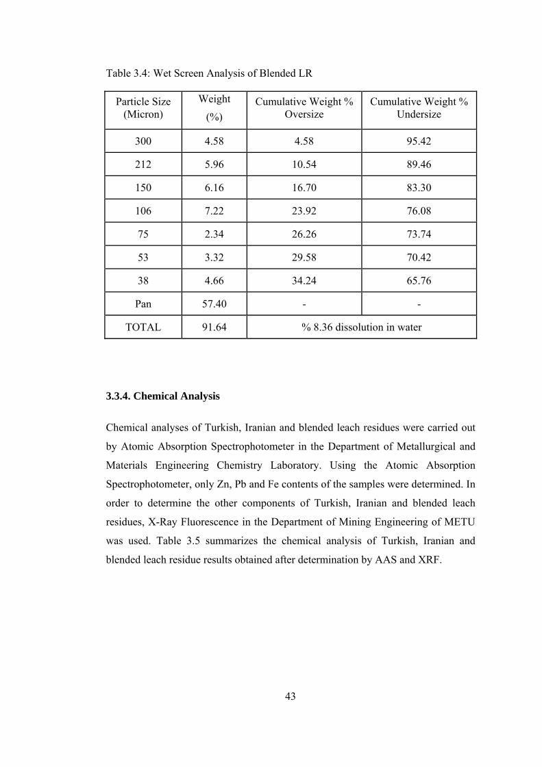
43
Table 3.4: Wet Screen Analysis of Blended LR
Particle Size (Micron)
Weight
(%) Cumulative Weight %
Oversize Cumulative Weight %
Undersize
300 4.58 4.58 95.42
212 5.96 10.54 89.46
150 6.16 16.70 83.30
106 7.22 23.92 76.08
75 2.34 26.26 73.74
53 3.32 29.58 70.42
38 4.66 34.24 65.76
Pan 57.40 - -
TOTAL 91.64 % 8.36 dissolution in water
3.3.4. Chemical Analysis
Chemical analyses of Turkish, Iranian and blended leach residues were carried out
by Atomic Absorption Spectrophotometer in the Department of Metallurgical and
Materials Engineering Chemistry Laboratory. Using the Atomic Absorption
Spectrophotometer, only Zn, Pb and Fe contents of the samples were determined. In
order to determine the other components of Turkish, Iranian and blended leach
residues, X-Ray Fluorescence in the Department of Mining Engineering of METU
was used. Table 3.5 summarizes the chemical analysis of Turkish, Iranian and
blended leach residue results obtained after determination by AAS and XRF.

44
Table 3.5: Chemical Analysis Results of Turkish, Iranian and Blended Leach Residues
Component Turkish LR (wt %)
Iranian LR (wt %)
Blended LR (wt %)
Pb 16.45 8.26 15.51
Zn 11.89 16.31 12.43
Fe 6.79 5.53 6.27
Cd 0.04 0.21 0.05
SO3 19.72 22.50 20.48
SiO2 15.86 20.11 17.18
CaO 8.50 4.19 7.57
Al2O3 3.91 6.58 3.99
MnO 0.58 1.71 0.79
MgO 0.95 1.29 0.98
K2O 0.01 0.98 0.14
BaO 0.44 0.28 0.36
From the results, it was found that Zn, Pb and Fe contents of blended LR were
12.43%, 15.51% and 6.27%, respectively. In addition, from Table 3.5, it can be seen
that the amounts of several elements or compounds such as Zn, SiO2, Al2O3, MnO,
MgO and K2O in Iranian LR were higher than those in Turkish LR. On the other
hand, Turkish LR contained more Pb, Fe, and CaO.
3.3.5. XRD Analysis
X-Ray Diffraction (XRD) was used in this study to analyze the mineral composition
of Iranian, Turkish and blended leach residues. The peaks of diffraction were
recorded and plotted against a horizontal scale in degrees of 2θ, which is the angle

45
of the detector rotation in order to catch the diffracted X-Ray. The XRD results of
Turkish, Iranian and blended leach residues have been presented in Figures 3.1, 3.2
and 3.3, respectively.
In previous studies [32, 54] Çinkur leach residue was exposed to a series of
selective zinc extraction tests and these tests indicated that zinc was present in the
residue as sulphate, ferrite, silicate and complex oxide forms. Most of these phases
can be also seen from the XRD results of all the leach residues. In XRD pattern of
blended LR, lead sulphate (PbSO4) and calcium sulphate hemihydrate
(CaSO4.½H2O) were identified as major components. The others were identified as
minor components. Although the peaks of major phases overlapped on peaks of
minor phases, other compounds could be identified as iron silicate (Fe2SiO4), zinc
ferrite (ZnFe2O4), zinc silicate (Zn2SiO4), zinc sulphate heptahydrate
(ZnSO4.7H2O), iron oxide (Fe2O3), calcium silicate (Ca2SiO4), and quartz (SiO2).
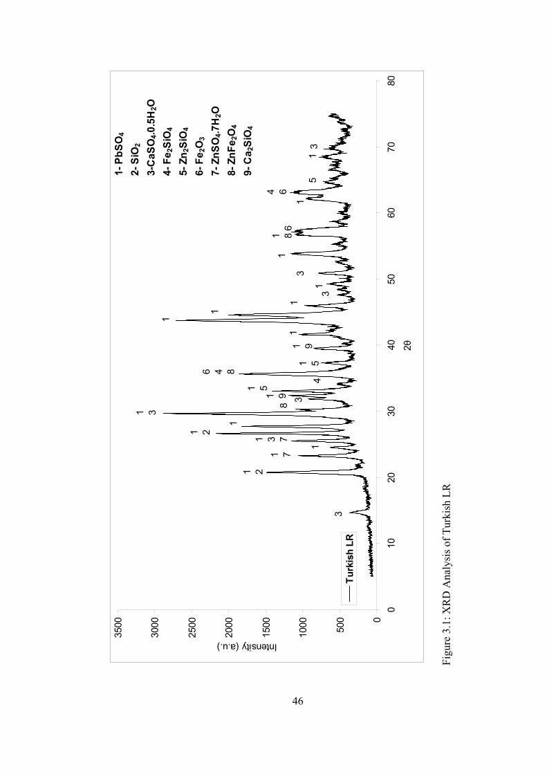
46
0
500
1000
1500
2000
2500
3000
3500
010
2030
4050
6070
80
2θ
Intensity (a.u.)
Turk
ish
LR
1- P
bSO
4
2- S
iO2
3-C
aSO
4.0.5
H2O
4- F
e 2Si
O4
5- Z
n 2Si
O4
6- F
e 2O
3
7- Z
nSO
4.7H
2O8-
ZnF
e 2O
4
9- C
a 2Si
O4
11 8
61
1 5
6 4 8
4
1 5
8
1 3
1
1 2
1 3 7
1
1 7
1 2
3
1 91
1
1
11 9
3
13
4 6
5 1
3 3
Fig
ure
3.1:
XR
D A
naly
sis o
f Tur
kish
LR
46

47
0
500
1000
1500
2000
2500
3000
010
2030
4050
6070
802θ
Intensity (a.u.)
Irani
an L
R
1 21
1 2
73
4 6 8
1 1
5 5
1 3
7
7
1
1 88
17
1
1 93
1 7
1
1- P
bSO
4
2- S
iO2
3-Ca
SO4.0
.5H 2
O4-
Fe 2
SiO
4
5- Z
n 2Si
O4
6- F
e 2O
3
7- Z
nSO
4.7H 2
O8-
ZnF
e 2O
4
9- C
a 2Si
O4
32
Fig
ure
3.2:
XR
D A
naly
sis o
f Ira
nian
LR
47

48
0
500
1000
1500
2000
2500
3000
3500
010
2030
4050
6070
80
2θ
Intensity (a.u.)
Ble
nded
LR
3
81
1
1 4
1 81 9
1 7
4 6 8
4
1 5 91 3 5
1 3 7
1
1 2
1 3 7 1
1 7
1 2
3
1
8 1 8
2
1
1
4 81
13
11 51-
PbS
O4
2- S
iO2
3-C
aSO
4.0.5
H2O
4- F
e 2S
iO4
5- Z
n 2S
iO4
6- F
e 2O
3
7- Z
nSO
4.7H
2O8-
ZnF
e 2O
4
9- C
a 2S
iO4
6
Figu
re 3
.3: X
RD
Ana
lysi
s of B
lend
ed L
R
48
49
3.3.6. SEM Analysis
Although there are various compounds or phases present in the blended LR, Turkish
LR and Iranian LR as seen in the XRF and XRD analyses of TLR, ILR and BLR,
some of them could not be determined such as those including Al, Mg, K, etc.
Therefore, in order to analyze these residues in detail, Scanning Electron
Microscopy (SEM) studies were done on gold coated samples and for this purpose
JEOL JMS 6400 type SEM equipped with EDS Tracor Series II analysis system
available in the Metallurgical and Material Engineering Department was used. Bulk
area analyses for Turkish, Iranian and blended leach residues can be seen in Figures
3.4, 3.5, and 3.6 and in Tables 3.6, 3.7, and 3.8, respectively.
In general, SEM analyses results of the residues showed parallelism with the results
of XRF, AAS and XRD. Differently, the results of SEM analyses proved that some
complex compounds including Al, Mg and K existed in the residues. Moreover,
from EDS analysis of the residues (Tables 3.6 and 3.7) it can be seen that Al, Mg
and K in Iranian LR were present more in amount as compared to Turkish LR.
Except for bulk area analyses of the residues, specific particle analyses were also
done to identify different phases in the residues. These particle analyses helped us
to detect and characterize the large particles such as SiO2, PbSO4, and CaSO4.½H2O
etc. in the residues. Due to the very fine particle size of the residues, all the phases
could not be identified because of the resulting interference.

50
Figure 3.4: SEM Analysis of Turkish LR Table 3.6: EDS Analysis of Turkish LR
Element Weight Concentration (%) Atom Concentration (%)
Pb 17.26 3.85
Zn 10.49 5.04
Fe 7.42 3.79
O 34.21 62.86
S 7.85 6.11
Si 7.66 7.92
Ca 6.59 5.47
Al 1.10 1.24
K 0.27 0.21
Mg 0.66 1.44
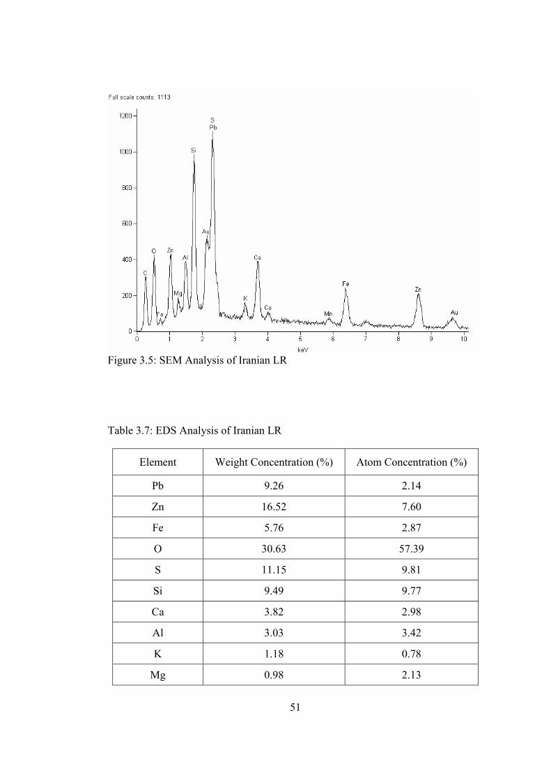
51
Figure 3.5: SEM Analysis of Iranian LR
Table 3.7: EDS Analysis of Iranian LR
Element Weight Concentration (%) Atom Concentration (%)
Pb 9.26 2.14
Zn 16.52 7.60
Fe 5.76 2.87
O 30.63 57.39
S 11.15 9.81
Si 9.49 9.77
Ca 3.82 2.98
Al 3.03 3.42
K 1.18 0.78
Mg 0.98 2.13
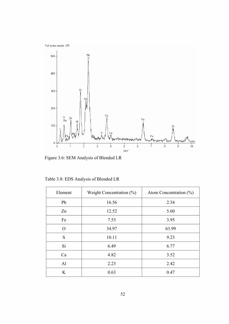
52
Figure 3.6: SEM Analysis of Blended LR Table 3.8: EDS Analysis of Blended LR
Element Weight Concentration (%) Atom Concentration (%)
Pb 16.56 2.34
Zn 12.52 5.60
Fe 7.53 3.95
O 34.97 63.99
S 10.11 9.23
Si 6.49 6.77
Ca 4.82 3.52
Al 2.23 2.42
K 0.63 0.47

53
3.3.7. Thermal Analysis
Thermogravimetric analysis (TGA) was carried out to find out the thermal behavior
of blended LR from 30oC to 980oC. 100 mg of blended LR sample was analyzed
with a linear heating rate of 25oC/min in N2 by the Central Laboratory at METU.
Result of the thermogravimetric analysis is given in Figure 3.7.
Weight loss occurring during thermogravimetric analysis can be explained by
evaporation of the chemically bonded water and several decompositions. Blended
LR contains two compounds including chemically bonded water. These compounds
are zinc sulphate heptahydrate (ZnSO4.7H2O) and calcium sulphate hemihydrate
(CaSO4.½H2O). Dehydration of zinc sulphate heptahydrate initially occurs on
heating to about 120oC. At this point, 6 moles of water is removed. On further
heating, two new peaks are observed on the TGA curve at around 300oC and 380oC
so 1 mole of water is lost at these temperatures [55]. Dehydration reactions (3.1,
3.2) occur as follow;
ZnSO4.7H2O = ZnSO4.H2O (- 6H2O) (at 120oC) (3.1)
ZnSO4.H2O = ZnSO4 (- H2O) (at 300oC and 380oC) (3.2)
On the other hand, dehydration of calcium sulphate hemihydrate occurs
approximately at the same temperatures with dehydration of zinc sulphate
heptahydrate. During heating, dehydration of calcium sulphate hemihydrate
(CaSO4.½H2O), also starts at 110oC and continues up to about 220oC. When the
hemihydrate is heated further, anhydrite calcium sulphate (CaSO4) forms according
to following reaction (3.3) [56].
CaSO4.½H2O = CaSO4 (-½H2O) (at 110-220oC) (3.3)
After the loss of water from the compounds, decomposition of zinc sulphate and
decomposition of calcium sulphate occur at different temperatures.
Desulphurization of anhydrous zinc sulphate (ZnSO4) begins at about 600oC and
ends at 930oC, so only ZnO remains in the residue [55]. On the other hand, in the

54
pure state anhydrite calcium sulphate does not show any thermal transformation
until 1200oC [56]. Therefore, desulphurization of the calcium sulphate on the TGA
curve is not observed.
As a result, the free moisture and chemically bonded water removal in
CaSO4.½H2O and ZnSO4.7H2O start at 110oC and these are completely removed
until about 380oC. Above this temperature, there is no water in the residue. Then,
desulphurization of the anhydrous sulphate begins at about 600oC. All these effects
can be seen in Figure 3.7.
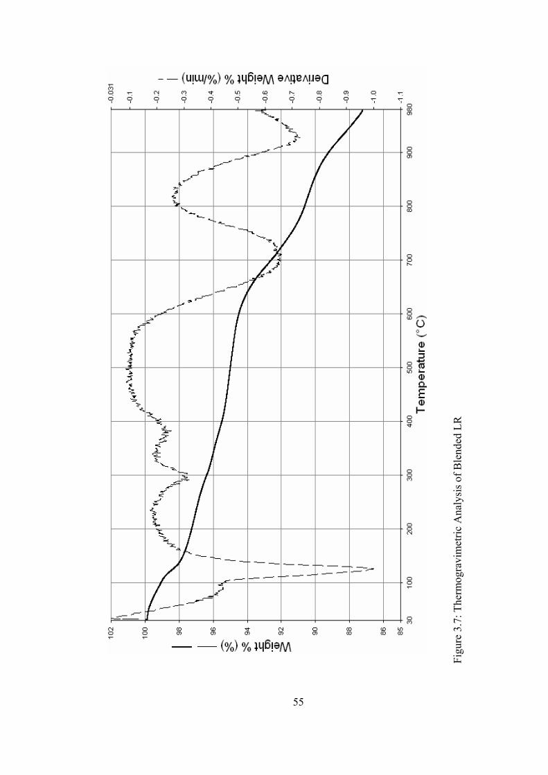
55
Figu
re 3
.7: T
herm
ogra
vim
etric
Ana
lysi
s of B
lend
ed L
R
55
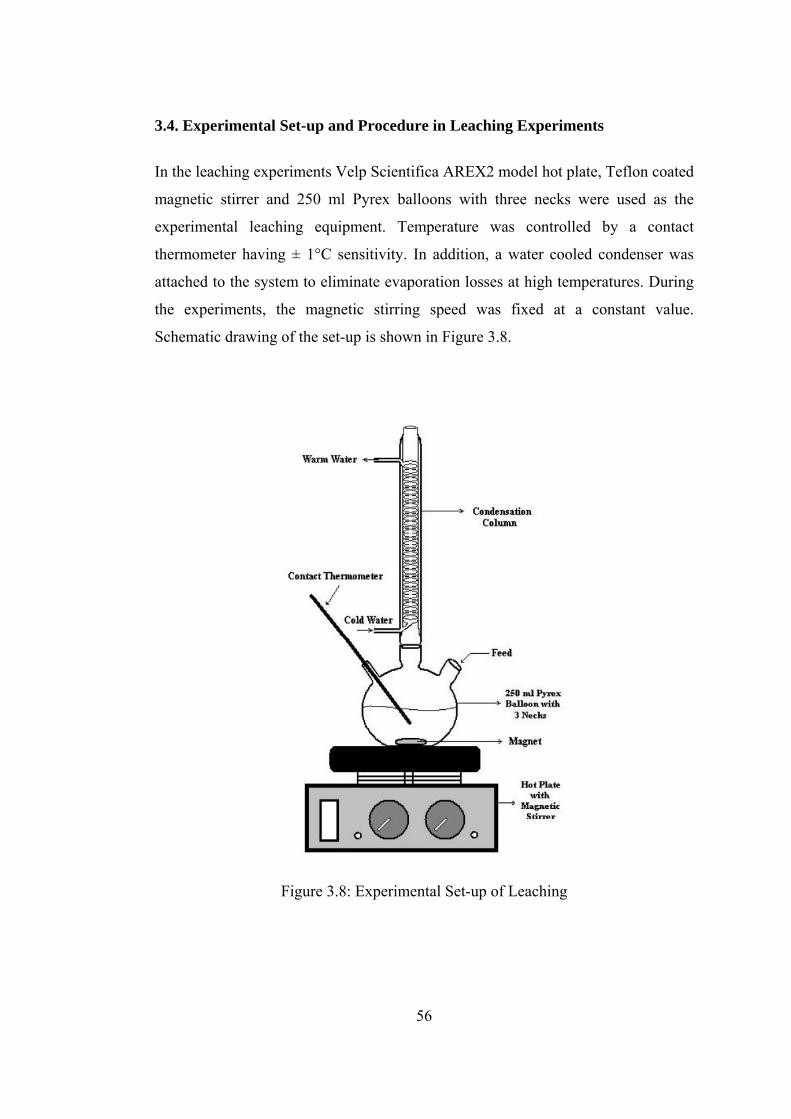
56
3.4. Experimental Set-up and Procedure in Leaching Experiments
In the leaching experiments Velp Scientifica AREX2 model hot plate, Teflon coated
magnetic stirrer and 250 ml Pyrex balloons with three necks were used as the
experimental leaching equipment. Temperature was controlled by a contact
thermometer having ± 1°C sensitivity. In addition, a water cooled condenser was
attached to the system to eliminate evaporation losses at high temperatures. During
the experiments, the magnetic stirring speed was fixed at a constant value.
Schematic drawing of the set-up is shown in Figure 3.8.
Figure 3.8: Experimental Set-up of Leaching

57
Leaching experiments were started with water leaching. These trials were
performed only to determine water solubility of the residues. Reaction temperature
and reaction duration were chosen in range of 25-95oC and 1-3 h, respectively.
In addition sulphuric acid leaching experiments were done to determine the
recovery of zinc. Experimental variables were chosen as temperature (25-99oC),
reaction duration (1-32 h), acid concentration (0-350 g/l) and solid to liquid ratio
(pulp density) (1/4-1/6 g/cc).
At the last stage, secondary leach residue (SLR) obtained at the end of acid leaching
trials was treated with brine solution for the recovery of lead. The effects of NaCl
concentration (0-300g/l), solid to liquid ratio (1/4-1/40 g/cc), leaching temperature
(25-102oC) and reaction duration (5-300 min.) were chosen as the experimental
parameters.
Except for pulp density trials, all of the leaching experiments were carried out with
20 grams of blended LR or SLR and 100 ml volume solution which was composed
of de-ionized water and predefined amount of leachant (sulphuric acid or sodium
chloride). During all of these tests, de-ionized water, Merck quality sulphuric acid
(95-98 wt%), hydrochloric acid (35 wt%) and sodium chloride (99.5 wt%) were
used.
After each leaching experiment, the solution was filtered by a vacuum pump using
S&S brand filter papers with blue band. Firstly, the filter paper was weighed and
placed into a Buchner funnel. Then, leach solution was poured onto the filter paper
carefully and slowly to separate pregnant leach solution from solid leach residue.
Then, the solid sample remaining on the filter paper was washed with de-ionized
water. After washing, solid residue with the filter paper was taken out of the
Buchner funnel and was put onto a watch glass. Then, the watch glass was placed
into a drying oven preheated to 105oC and kept there for about 3 hours. After
drying, filter cake was weighed again to determine the weight of each leach residue
and sent to the chemical laboratory for analyzing Zn, Pb and Fe by AAS. The
obtained results were used to calculate leach recoveries of Zn, Fe and Pb.

58
CHAPTER IV
RESULTS AND DISCUSSION
4.1 Introduction
In order to determine the leachability of blended LR of Çinkur with water, sulphuric
acid and brine under atmospheric pressure, a series of tests were carried out. In
these tests, the effect of acid concentration, pulp density (solid/liquid ratio), reaction
duration, leaching temperature and brine concentration as well as HCl additions
were investigated. The results are presented in the following sections.
4.2. Water Leaching
Initial experiments were done with de-ionized water by using the experimental set-
up given in Chapter III. In water leaching trials reaction duration (1-3 h) and
reaction temperature (25-95oC) were selected as the parameters to be investigated.
These leaching trials were performed to determine zinc recovery from blended LR
in water.
In the thesis, recovery term was used to state the amount of metal which could be
taken into the leach solution. For water, acid and brine leaching different recovery
equations were used in order to calculate metal recovery. In the water leaching part,
the recovery of zinc was calculated by using the following equation (4.1):
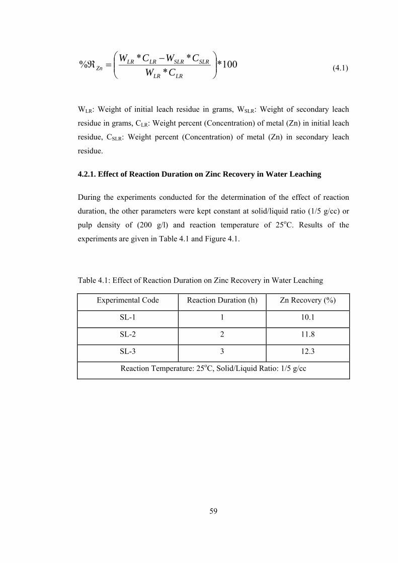
59
100**
**% ⎟⎟⎠
⎞⎜⎜⎝
⎛ −=ℜ
LRLR
SLRSLRLRLRZn CW
CWCW (4.1)
WLR: Weight of initial leach residue in grams, WSLR: Weight of secondary leach
residue in grams, CLR: Weight percent (Concentration) of metal (Zn) in initial leach
residue, CSLR: Weight percent (Concentration) of metal (Zn) in secondary leach
residue.
4.2.1. Effect of Reaction Duration on Zinc Recovery in Water Leaching
During the experiments conducted for the determination of the effect of reaction
duration, the other parameters were kept constant at solid/liquid ratio (1/5 g/cc) or
pulp density of (200 g/l) and reaction temperature of 25oC. Results of the
experiments are given in Table 4.1 and Figure 4.1.
Table 4.1: Effect of Reaction Duration on Zinc Recovery in Water Leaching
Experimental Code Reaction Duration (h) Zn Recovery (%)
SL-1 1 10.1
SL-2 2 11.8
SL-3 3 12.3
Reaction Temperature: 25oC, Solid/Liquid Ratio: 1/5 g/cc

60
0
5
10
15
0 1 2 3Reaction Duration (h)
Rec
over
y %
Zn
Figure 4.1: Effect of Reaction Duration on Zinc Recovery in Water Leaching. From the results, it is seen that beyond 1 h of leaching duration, the increase in
leach recovery of zinc was not substantial. As a result of this, it can be said that in
one hour most of the zinc that was recoverable by water leaching from blended LR
was taken into solution.
4.2.2. Effect of Reaction Temperature on Zinc Recovery in Water Leaching
Effect of temperature was investigated by choosing solid/liquid ratio as 1/5 g/cc and
reaction duration as 1 h. Results of the trials are given in Table 4.2 and Figure 4.2.
Table 4.2: Effect of Reaction Temperature on Zinc Recovery in Water Leaching
Experimental Code Reaction Temperature (oC) Zn Recovery (%)
SL-1 25 10.1
SL-4 45 14.8
SL-5 95 18.4
Reaction Duration: 1 h, Solid/Liquid Ratio: 1/5 g/cc

61
5
10
15
20
20 40 60 80 100Reaction Temp. (°C )
Reco
very
%
Zn
Figure 4.2: Effect of Reaction Temperature on Zinc Recovery in Water Leaching As it can be seen from these results, the recovery of zinc increased with the
increasing reaction temperature and reached a maximum value at 95oC. Therefore,
this value can be chosen as the optimum reaction temperature.
As mentioned before, blended LR contains many compounds including ZnFe2O4,
Zn2SiO4, ZnSO4.7H2O, PbSO4 and others. However, in water leaching experiments,
zinc recovery was restricted by the amount of ZnSO4.7H2O in blended LR, because
only ZnSO4.7H2O is soluble in water. In conclusion, it can be said that zinc
recovery in water leaching increased with increasing reaction duration especially in
the first hour and increasing reaction temperature. The maximum zinc recovery in
water leaching experiments was found to be about 18% which was due to the
presence of limited amount of zinc in blended LR as ZnSO4.7H2O. In the light of
these results it was concluded that percentage of zinc originating from zinc
heptahydrate was (12.43*18/100=2.23%) 2.23% which corresponded to 9.85%
ZnSO4.7H2O (2.23*287/65=9.85%) in blended LR.
4.3. Acid Leaching
Due to insufficient zinc recoveries of water leaching tests and the presence of acid
soluble compound such as zinc ferrite in the leach residues, acid leaching tests were
done for zinc recovery. During acid leaching experiments, as a leachant, sulphuric
62
acid (H2SO4) solution was used. When the blended leach residue was subjected to
sulphuric acid solution, zinc ferrite (ZnFe2O4) in the leach residue was converted to
water soluble zinc sulphate (ZnSO4) according to reaction (4.2) [57]. Other zinc
forms, such as silicate and complex, in the blended LR did not react with sulphuric
acid [1].
ZnFe2O4(s) + 4 H2SO4(aq) = ZnSO4(aq) + Fe2(SO4)3(aq) + 4 H2O (4.2)
In acid leaching, variables chosen were acid concentration (0-350 g/l), reaction
duration (1-32 h), reaction temperature (25-99oC), and solid/liquid ratio
(1/4-1/6 g/cc). In the experiments, the recovery of zinc and dissolution of iron were
calculated by using the following formula (4.3):
100**
**% , ⎟⎟⎠
⎞⎜⎜⎝
⎛ −=ℜ
LRLR
SLRSLRLRLRFeZn CW
CWCW (4.3)
WLR: Weight of initial leach residue in grams, WSLR: Weight of secondary leach
residue in grams, CLR: Weight percent (Concentration) of metal (Zn or Fe) in initial
leach residue, CSLR: Weight percent (Concentration) of metal (Zn or Fe) in
secondary leach residue.
4.3.1. Effect of H2SO4 Concentration on Zinc Recovery in Acid Leaching
In this study, blended LR was tested at five different levels of sulphuric acid
concentrations, which were 50, 100, 150, 250 and 350 g/l. During the tests, the
following parameters were kept constant: Solid/liquid ratio: 1/5 (g/cc); reaction
duration: 1 hour; reaction temperature: 95oC.
Zinc recoveries with changing sulphuric acid concentration are given in Table 4.3
and Figure 4.3. Results showed that the concentration of sulphuric acid was a very
important parameter for zinc recovery. It was playing a significant role on the
recovery of zinc and dissolution of iron. Increasing acid concentration caused
increases in zinc recovery but also undesirable increases in iron dissolution.
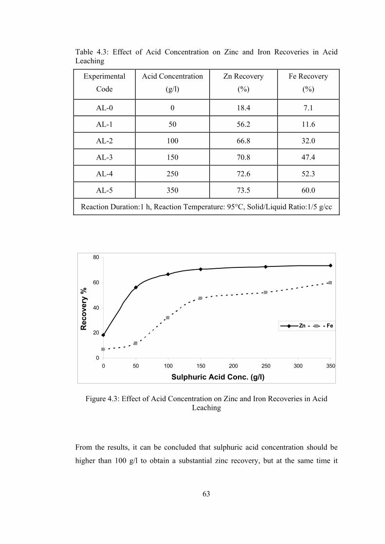
63
Table 4.3: Effect of Acid Concentration on Zinc and Iron Recoveries in Acid Leaching
Experimental
Code
Acid Concentration
(g/l)
Zn Recovery
(%)
Fe Recovery
(%)
AL-0 0 18.4 7.1
AL-1 50 56.2 11.6
AL-2 100 66.8 32.0
AL-3 150 70.8 47.4
AL-4 250 72.6 52.3
AL-5 350 73.5 60.0
Reaction Duration:1 h, Reaction Temperature: 95°C, Solid/Liquid Ratio:1/5 g/cc
0
20
40
60
80
0 50 100 150 200 250 300 350
Sulphuric Acid Conc. (g/l)
Rec
over
y %
Zn Fe
Figure 4.3: Effect of Acid Concentration on Zinc and Iron Recoveries in Acid Leaching
From the results, it can be concluded that sulphuric acid concentration should be
higher than 100 g/l to obtain a substantial zinc recovery, but at the same time it

64
should be lower than 150 g/l to limit iron dissolution. It should also be kept in mind
that the spent liquor generated as a result of zinc electrolysis which is to be used in
acid leaching contains 150 g/l sulphuric acid. Moreover, other researchers who have
studied leaching of zinc ferrite with sulphuric acid solution stated that sufficient
zinc recoveries could be obtained by using more than 100 g/l H2SO4 at 90-95oC
temperature range in 2-4 hours reaction duration [34, 37, 58].
4.3.2. Effect of Reaction Duration on Zinc Recovery in Acid Leaching
In order to see the effect of reaction duration on zinc recovery, leaching tests were
carried out for 1, 2, 3, 6, 16, 24 and 32 hours. During these tests, other parameters
such as; acid concentration, solid/liquid ratio, and reaction temperature were kept
constant as 150 g/l, 1/5 g/cc, 95oC, respectively. The results of the experiments are
given in Table 4.4 and Figure 4.4.
Table 4.4: Effect of Reaction Duration on Zinc and Iron Recoveries in Acid Leaching
Experimental
Code
Reaction Duration
(h)
Zn Recovery
(%)
Fe Recovery
(%)
AL-3 1 70.8 47.4
AL-6 2 71.9 49.0
AL-7 3 73.4 50.9
AL-8 6 74.9 57.9
AL-9 16 80.0 64.5
AL-10 24 82.8 70.9
AL-11 32 82.8 72.1
Acid Conc.:150 g/l, Reaction Temp.: 95°C, Solid/Liquid Ratio:1/5 g/cc
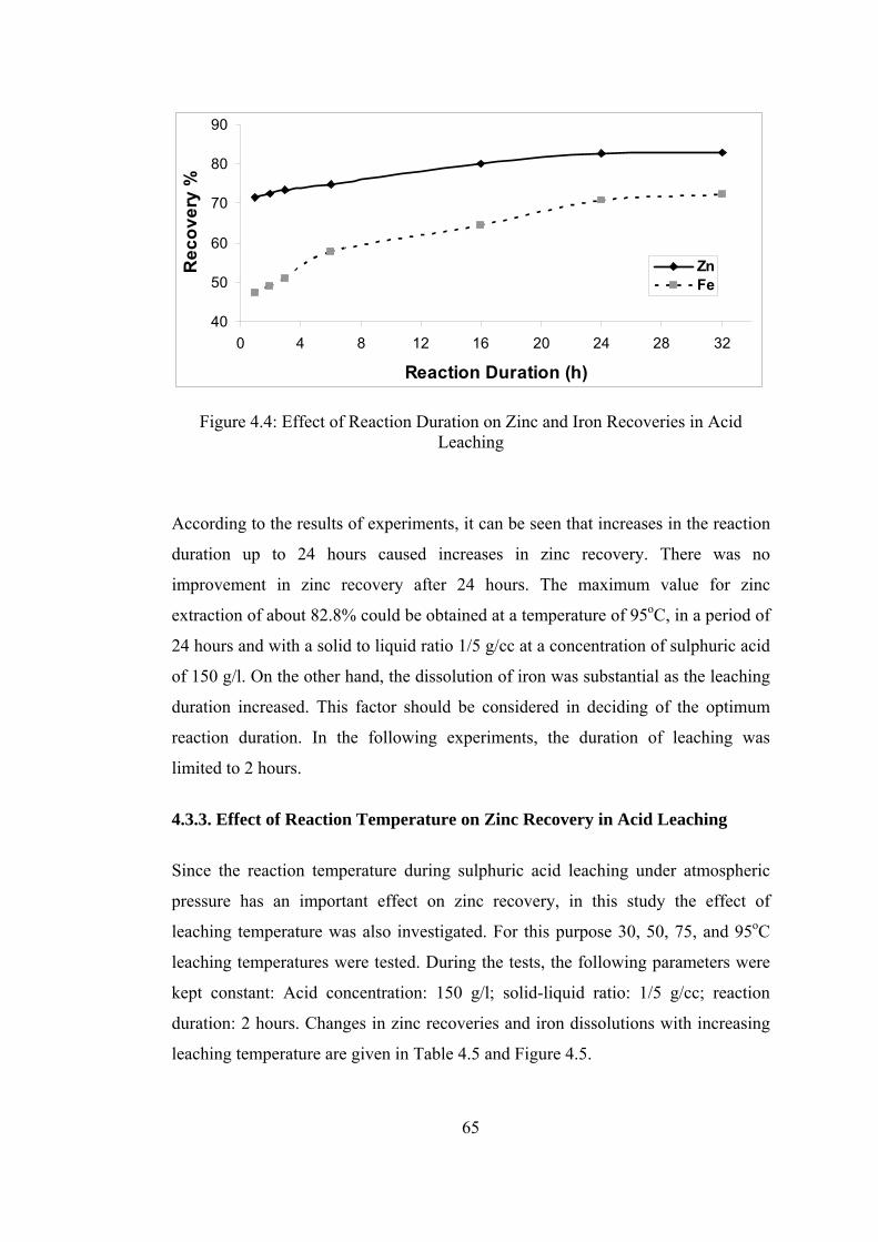
65
40
50
60
70
80
90
0 4 8 12 16 20 24 28 32
Reaction Duration (h)
Rec
over
y %
ZnFe
Figure 4.4: Effect of Reaction Duration on Zinc and Iron Recoveries in Acid Leaching
According to the results of experiments, it can be seen that increases in the reaction
duration up to 24 hours caused increases in zinc recovery. There was no
improvement in zinc recovery after 24 hours. The maximum value for zinc
extraction of about 82.8% could be obtained at a temperature of 95oC, in a period of
24 hours and with a solid to liquid ratio 1/5 g/cc at a concentration of sulphuric acid
of 150 g/l. On the other hand, the dissolution of iron was substantial as the leaching
duration increased. This factor should be considered in deciding of the optimum
reaction duration. In the following experiments, the duration of leaching was
limited to 2 hours.
4.3.3. Effect of Reaction Temperature on Zinc Recovery in Acid Leaching
Since the reaction temperature during sulphuric acid leaching under atmospheric
pressure has an important effect on zinc recovery, in this study the effect of
leaching temperature was also investigated. For this purpose 30, 50, 75, and 95oC
leaching temperatures were tested. During the tests, the following parameters were
kept constant: Acid concentration: 150 g/l; solid-liquid ratio: 1/5 g/cc; reaction
duration: 2 hours. Changes in zinc recoveries and iron dissolutions with increasing
leaching temperature are given in Table 4.5 and Figure 4.5.

66
Table 4.5: Effect of Reaction Temperature on Zinc and Iron Recoveries in Acid Leaching
Experimental
Code
Reaction Temperature
(oC)
Zn Recovery
(%)
Fe Recovery
(%)
AL-12 30 63.7 22.3
AL-13 50 65.6 33.8
AL-14 75 67.3 40.0
AL-6 95 71.9 49.0
Acid Conc.:150 g/l, Reaction Duration: 2 h, Solid/Liquid Ratio:1/5 g/cc
20
40
60
80
25 50 75 100
Reaction Temp. ( oC)
Rec
over
y %
Zn Fe
Figure 4.5: Effect of Reaction Temperature on Zinc and Iron Recoveries in Acid Leaching
These results indicated that increasing temperatures caused increasing zinc
recoveries as well as iron dissolutions. Therefore, the optimum leaching
temperature was chosen to be 95oC.

67
At this temperature, the leach solution containing 150 g/l H2SO4 does not boil.
During boiling of the leach solution, it may not be necessary to stir the liquid.
Therefore, at the end of the study on the effect of reaction temperature, the boiling
point of leach solution having 150 g/l H2SO4 was determined as 99oC. After a trial
at the boiling point without magnetic stirring, approximately 70.4% recovery of Zn
was obtained with 150 g/l acid concentration in 2 hours reaction duration at 200 g/l
pulp density. Under these conditions, the dissolution of iron was calculated as
42.2%. It can therefore be stated that stirring of the solution had a small positive
effect on the recovery of zinc, but it negatively affected the iron dissolution.
4.3.4. Effect of Solid/Liquid Ratio on Zinc Recovery in Acid Leaching
In the study, in order to see the effect of pulp density three different solid-liquid
ratios, namely 1/4, 1/5, and 1/6 g/cc, were investigated. During these experiments
the other parameters were kept constant: Acid concentration: 150 g/l, reaction
duration: 2 hours; reaction temperature: 95oC. The experimental results are given in
Table 4.6 and in Figure 4.6.
Table 4.6: Effect of Solid/Liquid Ratio on Zinc and Iron Recoveries in Acid Leaching
Experimental
Code
Solid/Liquid Ratio
(g/cc)
Zn Recovery
(%)
Fe Recovery
(%)
AL-15 ¼ 69.6 48.0
AL-6 1/5 71.9 49.0
AL-16 1/6 72.5 46.9
Acid Conc.:150 g/l, Reaction Temp.: 95°C, Reaction Duration: 2 h

68
40
50
60
70
80
0 1/7 1/5 1/4
Solid/Liquid Ratio (g/cc)
Rec
over
y %
ZnFe
Figure 4.6: Effect of Solid/Liquid Ratio on Zinc and Iron Recoveries in Acid Leaching
From Figure 4.6, it is seen that the recovery of zinc slightly increased with
decreasing pulp density. So, the change of solid/liquid ratio was very slightly
effective on zinc recovery in the studied range.
In conclusion of sulphuric acid leaching experiments, it can be said that as zinc
recovery increased, also iron dissolution increased. In order to minimize iron
removal expenses at purification stage, acid concentration and reaction duration
have to be limited. Therefore, the optimum hot acid leaching conditions were
determined for the initial sulphuric acid concentration as 150g/l, reaction duration
as 2 h, leaching temperature as 95°C, solid/liquid ratio as 1/5. At these conditions
zinc recovery was found to be 71.9%. At longer leaching durations, the recovery of
zinc could be increased but this would be accompanied by a substantial increase in
iron contamination of the pregnant leach solution.
At the end of acid leaching of blended LR, in order to see the effect of the optimum
hot acid leaching conditions on Turkish LR and Iranian LR, they were leached
separately. Results of these experiments are given in Table 4.7.

69
Table 4.7: Acid Leaching of Turkish and Iranian Leach Residues
Sample Zn Recovery (%) Fe Recovery (%)
Turkish LR 68.8 46.5
Iranian LR 95.1 75.2
Acid Conc.: 150 g/l, Reaction Temp.: 95oC, Reaction Duration: 2 h, Solid/Liquid Ratio: 1/5 (g/cc)
As stated earlier, in acid leaching process, amount of zinc ferrite (ZnFe2O4) and
zinc sulphate heptahydrate (ZnSO4.7H2O) in the LR determine the zinc recovery
value. Therefore, in view of the Table 4.7, it can be said that the amounts of zinc
ferrite (ZnFe2O4) and zinc sulphate heptahydrate (ZnSO4.7H2O) in Iranian LR were
higher than those in Turkish LR.
It is seen from Table 4.7 that zinc recovery for Iranian LR was very high. But
Iranian LR is limited in amount when compared to Turkish LR and in some places
they are mixed with each other in Çinkur stockpile. Therefore, it can be said that the
use of only Iranian LR is not very meaningful for zinc recovery. As a result,
blended LR was used in all the remaining experiments.
Then, sufficient amount of blended LR was leached with sulphuric acid under the
optimum hot acid leaching conditions in order to prepare a stock and to use in lead
recovery experiments. After several experiments, approximately 1 kg of stock was
prepared to be used in brine leaching part for lead recovery. In the stock preparation
experiments, the average value of zinc recovery was calculated as 71.0%.
Reproducible results were obtained in the range of ± 2% of the stated value.
In order to determine the acidity of pregnant leach solution obtained after the
chosen hot acid leaching trial (AL-6), titration of the pregnant leach solution was
done by using 0.2 N NaOH. It is found that about 85 g/l of the initial 150g/l H2SO4
had remained in the solution after acid leaching. This result indicated that 65 g/l

70
H2SO4 was consumed for the recovery of zinc from zinc ferrite. Calculations done
for this trial is given in Appendix A.
Considering the blended LR, it can be seen that acid consumption was almost
completely spent by zinc ferrite. Therefore, the stoichiometrically needed acid
consumption value was calculated in accordance with the zinc ferrite amount.
Results of these calculations are given in Appendix B and C, showing that quantity
of sulphuric acid used in the acid experiments was approximately twice as much as
the stoichiometrically needed acid value.
At the end of water leaching experiments, the percentage of zinc originating from
zinc heptahydrate was determined as 2.23%. In the same way, percentage of zinc
originating from zinc ferrite was calculated by using the value obtained in
Appendix B, (12.43*65/100=8.08%) which corresponded to 29.96% ZnFe2O4
(8.08*241/65=29.96%) in blended LR.
As mentioned in Chapter 2, iron removal process is needed before the zinc
electrowinning step since pregnant solution obtained at the end of the optimum hot
acid leaching includes high amount of iron. In order to remove from the solution,
iron is precipitated as Hematite, Jarosite or Goethite which are the three types of
commonly used iron removal processes. Although hematite product is more
marketable, Jarosite process is more appropriate candidate due to more easily
applicable method than others [35].
After removal of the iron in the solution by using one of the mentioned methods,
pregnant leach solution goes through other purification stages to clean other
impurities. Finally, electrolytic zinc can be obtained by electrowinning process [38].
4.4. Brine (NaCl) Leaching
After the hot sulphuric acid leaching experiments reasonably high zinc recoveries
were accomplished with accompanied iron dissolution. In order to recover the lead
present in the secondary leach residue, salt leaching experiments were decided to be
performed. For this purpose, brine leaching experiments were done with 1 kg of
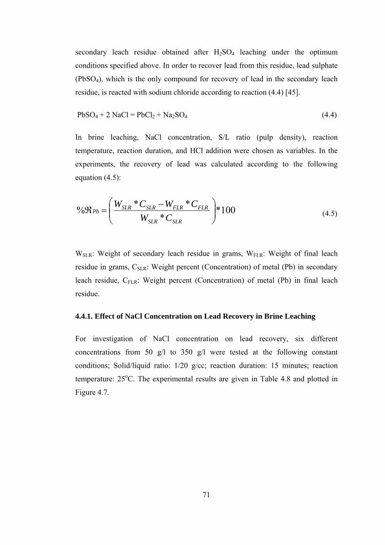
71
secondary leach residue obtained after H2SO4 leaching under the optimum
conditions specified above. In order to recover lead from this residue, lead sulphate
(PbSO4), which is the only compound for recovery of lead in the secondary leach
residue, is reacted with sodium chloride according to reaction (4.4) [45].
PbSO4 + 2 NaCl = PbCl2 + Na2SO4 (4.4)
In brine leaching, NaCl concentration, S/L ratio (pulp density), reaction
temperature, reaction duration, and HCl addition were chosen as variables. In the
experiments, the recovery of lead was calculated according to the following
equation (4.5):
100**
**% ⎟⎟⎠
⎞⎜⎜⎝
⎛ −=ℜ
SLRSLR
FLRFLRSLRSLRPb
CWCWCW
(4.5)
WSLR: Weight of secondary leach residue in grams, WFLR: Weight of final leach
residue in grams, CSLR: Weight percent (Concentration) of metal (Pb) in secondary
leach residue, CFLR: Weight percent (Concentration) of metal (Pb) in final leach
residue.
4.4.1. Effect of NaCl Concentration on Lead Recovery in Brine Leaching
For investigation of NaCl concentration on lead recovery, six different
concentrations from 50 g/l to 350 g/l were tested at the following constant
conditions; Solid/liquid ratio: 1/20 g/cc; reaction duration: 15 minutes; reaction
temperature: 25oC. The experimental results are given in Table 4.8 and plotted in
Figure 4.7.

72
Table 4.8: Effect of NaCl Concentration on Lead Recovery in Brine Leaching
Experimental Code NaCl Concentration (g/l) Pb Recovery (%)
BL-1 50 4.0
BL-2 100 7.9
BL-3 150 32.9
BL-4 200 62.7
BL-5 250 82.0
BL-6 300 95.0
Reaction Duration:15 min., Reaction Temp.:25°C, Solid/Liquid Ratio: 1/20 g/cc
0
20
40
60
80
100
0 50 100 150 200 250 300 350
NaCl Conc. (g/l)
Rec
over
y %
Pb
Pb
Figure 4.7: Effect of NaCl Concentration on Lead Recovery in Brine Leaching From these results, it can be concluded that the brine concentration is a very
effective parameter for lead recovery. As the NaCl concentration increased, lead
recovery increased significantly. Therefore, NaCl concentration should be chosen as
high as possible. However, it is suggested not to use greater than 350 g/l NaCl

73
concentration in brine leaching because when greater values are used NaCl solution
becomes saturated. NaCl solubility in grams per 100 cc cold water is given as 35.7
[1]. This means that maximum NaCl concentration can be chosen as 357 g/l.
Several researchers emphasized that in the solutions having high chloride
concentration, PbCl2 converts to PbCl3- and then to PbCl4
= complexes according to
reactions (4.6 and 4.7) due to their solubilities being higher than PbCl2. This results
in a increase in the concentration of Pb2+ ions in solution [9, 32, 59].
PbCl2 + Cl- = PbCl3- (4.6)
PbCl3- + Cl- = PbCl4
= (4.7)
4.4.2. Effect of Solid/Liquid Ratio on Lead Recovery in Brine Leaching
For this study, in order to see the effect of pulp density, the solid to liquid ratio was
varied between 1/5 and 1/40 g/cc when NaCl concentration, reaction temperature
and duration were kept as 250 g/l, 25°C and 15 minutes, respectively. The
experimental results are summarized in Table 4.9 and plotted in Figure 4.8. As seen
from Figure 4.8 that the lead recovery decreases with increasing pulp density.
Table 4.9: Effect of Solid/Liquid Ratio on Lead Recovery in Brine Leaching
Experimental Code Solid/Liquid Ratio (g/cc) Pb Recovery (%)
BL-8 1/5 20.3
BL-9 1/10 45.2
BL-5 1/20 82.0
BL-10 1/30 94.6
BL-11 1/40 96.3
NaCl Conc.: 250 g/l, Reaction Duration: 15 min., Reaction Temp.:25°C

74
0
20
40
60
80
100
0 0 0 1/4 1/4
Solid/Liquid Ratio (g/cc)
Rec
over
y %
Pb
Pb
1/8 0 1/20 1/10 1/8 1/5
Figure 4.8: Effect of Solid/Liquid Ratio on Lead Recovery in Brine Leaching It was seen from the results that the highest lead recovery was obtained with 1/40
solid to liquid ratio. However, this pulp density is unreasonably low for economical
use. When higher pulp densities were used, decreases in lead recoveries were
observed. The reason of this decrease was thought to be due to the fact that NaCl
concentration around residue particles was insufficient for dissolution of lead in
liquid NaCl solution.
4.4.3. Effect of HCl addition on Lead Recovery in Brine Leaching
Many researchers stated that lead solubility significantly increases with increasing
chloride ion, Cl-, in the solution [45, 46, 60, 61]. They added HCl to the leaching
solution with the aim of increasing the activity of Cl-
ions and to obtain maximum
lead recovery. For this purpose, in this study, 10 ml/l HCl was added to various
leach solutions at the following constant conditions: NaCl concentration: 300 g/l;
reaction duration: 30 minutes; reaction temperature: 25oC. Results of these trials are
tabulated in Table 4.10 and presented in Figure 4.9. Results indicated that HCl
addition had slightly affected lead recovery.

75
Table 4.10: Effect of HCl Addition on Lead Recovery at Various Solid/Liquid Ratios in Brine Leaching
Experimental
Code
Solid/Liquid Ratio
(g/cc)
Pb Recovery
(%)
HCl Addition
(ml/l)
BL-12 1/4 24.2 0 ml
BL-13 1/5 31.6 0 ml
BL-14 1/10 69.6 0 ml
BL-15 1/20 94.5 0 ml
BL-16 1/4 27.8 10 ml
BL-17 1/5 35.3 10 ml
BL-18 1/10 77.8 10 ml
BL-19 1/20 98.3 10 ml
NaCl Conc.: 300 g/l, Reaction Duration: 30 min., Reaction Temp.:25°C
20
40
60
80
100
0 1/20 1/10 3/20 1/5 1/4
Solid/Liquid Ratio (g/cc)
Rec
over
y %
Pb
HCl added: 0 mlHCl added: 10ml/l
1/8 0
Figure 4.9: Effect of HCl Addition on Lead Recovery at Various Solid/Liquid
Ratios in Brine Leaching

76
4.4.4. Effect of Reaction Temperature on Lead Recovery in Brine Leaching
It is known that reaction temperature is one of the most important factors which
affect the brine leaching process. In this study, the effect of temperature was
investigated for the leaching temperatures of 25, 50, 80, 95oC as well as at the
boiling point of 102oC. During the tests, NaCl concentration (300 g/l), reaction
duration (60 minutes) and solid to liquid ratio (1/5 g/cc) were kept constant. The
results of the experiments are given in Table 4.11 and presented in Figure 4.10.
Table 4.11: Effect of Reaction Temperature on Lead Recovery in Brine Leaching
Experimental Code Reaction Temp. (°C) Pb Recovery (%)
BL-20 25 33.2
BL-21 50 40.3
BL-22 80 72.9
BL-23 95 78.8
BL-24 102 79.8
NaCl Conc.: 300 g/L, Reaction Duration: 60 min., Solid/Liquid Ratio:1/5 g/cc
20
40
60
80
100
25 50 75 100
Reaction Temp. (oC)
Rec
over
y %
Pb
Pb
Figure 4.10: Effect of Reaction Temperature on Lead Recovery in Brine Leaching

77
As seen from the results, the brine leaching temperature was a very effective
parameter for lead recovery. Increases in the temperature beyond 50oC caused a
substantial increase in lead recovery. This implies that the brine leaching
temperature should be greater than 50oC. In addition, according to Habashi [62],
while solubility of PbSO4 in 0.25 N NaCl is 0.35 g/l at 25oC, it reaches 6.90 g/l at
120oC. It is shown that as the temperature increases, the solubility of lead also
increases.
4.4.5. Effect of Reaction Duration on Lead Recovery in Brine Leaching
The effect of reaction duration on brine leaching was investigated by varying the
reaction duration between 5 to 300 minutes. During the tests the following
parameters were kept constant: NaCl concentration: 300 g/l; reaction temperature
95oC; solid/liquid ratio: 1/5 g/cc. The results of the experiments are seen in Table
4.12 and Figure 4.11.
Table 4.12: Effect of Reaction Duration on Lead Recovery in Brine Leaching
Experimental Code Reaction Duration (min.) Pb Recovery (%)
BL-25 5 82.4
BL-26 10 84.9
BL-27 15 82.8
BL-28 30 79.7
BL-23 60 78.8
BL-29 180 74.6
BL-30 300 73.1
NaCl Conc.: 300 g/l, Reaction Temp.: 95°C , Solid/Liquid Ratio:1/5 g/cc
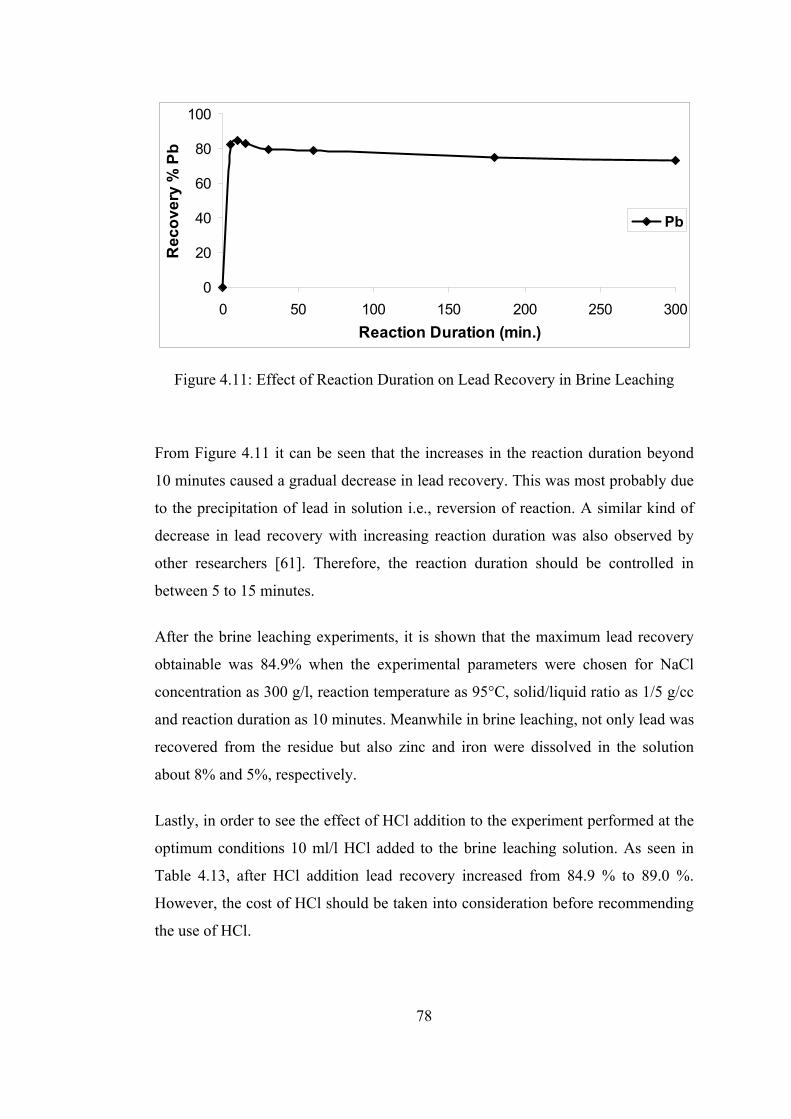
78
0
20
40
60
80
100
0 50 100 150 200 250 300Reaction Duration (min.)
Rec
over
y %
Pb
Pb
Figure 4.11: Effect of Reaction Duration on Lead Recovery in Brine Leaching From Figure 4.11 it can be seen that the increases in the reaction duration beyond
10 minutes caused a gradual decrease in lead recovery. This was most probably due
to the precipitation of lead in solution i.e., reversion of reaction. A similar kind of
decrease in lead recovery with increasing reaction duration was also observed by
other researchers [61]. Therefore, the reaction duration should be controlled in
between 5 to 15 minutes.
After the brine leaching experiments, it is shown that the maximum lead recovery
obtainable was 84.9% when the experimental parameters were chosen for NaCl
concentration as 300 g/l, reaction temperature as 95°C, solid/liquid ratio as 1/5 g/cc
and reaction duration as 10 minutes. Meanwhile in brine leaching, not only lead was
recovered from the residue but also zinc and iron were dissolved in the solution
about 8% and 5%, respectively.
Lastly, in order to see the effect of HCl addition to the experiment performed at the
optimum conditions 10 ml/l HCl added to the brine leaching solution. As seen in
Table 4.13, after HCl addition lead recovery increased from 84.9 % to 89.0 %.
However, the cost of HCl should be taken into consideration before recommending
the use of HCl.
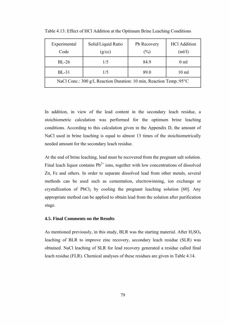
79
Table 4.13: Effect of HCl Addition at the Optimum Brine Leaching Conditions
Experimental
Code
Solid/Liquid Ratio
(g/cc)
Pb Recovery
(%)
HCl Addition
(ml/l)
BL-26 1/5 84.9 0 ml
BL-31 1/5 89.0 10 ml
NaCl Conc.: 300 g/l, Reaction Duration: 10 min, Reaction Temp.:95°C
In addition, in view of the lead content in the secondary leach residue, a
stoichiometric calculation was performed for the optimum brine leaching
conditions. According to this calculation given in the Appendix D, the amount of
NaCl used in brine leaching is equal to almost 13 times of the stoichiometrically
needed amount for the secondary leach residue.
At the end of brine leaching, lead must be recovered from the pregnant salt solution.
Final leach liquor contains Pb2+ ions, together with low concentrations of dissolved
Zn, Fe and others. In order to separate dissolved lead from other metals, several
methods can be used such as cementation, electrowinning, ion exchange or
crystallization of PbCl2 by cooling the pregnant leaching solution [60]. Any
appropriate method can be applied to obtain lead from the solution after purification
stage.
4.5. Final Comments on the Results
As mentioned previously, in this study, BLR was the starting material. After H2SO4
leaching of BLR to improve zinc recovery, secondary leach residue (SLR) was
obtained. NaCl leaching of SLR for lead recovery generated a residue called final
leach residue (FLR). Chemical analyses of these residues are given in Table 4.14.

80
Table 4.14: Chemical Analyses of Blended, Secondary and Final Leach Residues
Component Blended LR (wt %)
Secondary LR (wt %)
Final LR (wt %)
Pb 15.51 20.51 4.57
Zn 12.43 4.71 5.81
Fe 6.27 4.18 6.62
Cd 0.05 0.016 0.023
SO3 20.48 22.34 18.84
SiO2 17.35 25.03 38.47
CaO 7.57 7.99 9.90
Al2O3 3.99 3.79 5.48
MnO 0.79 0.17 0.18
MgO 0.98 0.39 0.41
K2O 0.14 0.22 0.47
BaO 0.36 0.49 0.65
As it can be seen from Table 4.14, Pb content is originally 15.51% in the BLR.
After acid leaching, secondary LR is obtained and the amount of Pb increases from
15.51% to 20.51% in the solid part due to the fact that PbSO4 is not leached in
sulphuric acid and the amount of solid residue decreases in weight by about 30%.
Similarly, after brine leaching, the weight of secondary LR declines further by
approximately 30% and final LR is obtained. In other words, more than half of the
blended leach residue is lost in weight until obtaining the final leach residue. It is
seen from Table 4.14 that these weight changes affect percents of the all dissolved
and undissolved elements in the residues. For example, while iron percent is 6.27%
in blended LR, it decreases to 4.18% then increases to 6.62% after acid and brine
leaching, respectively. That is, compounds including iron dissolve in acid leaching

81
and so the value of iron percentage decreases to 4.18% after acid leaching but it
increases to 6.62% after brine leaching due to little amount iron dissolution. Both
silicates and complex compounds are other examples. Since they are not dissolved
in both leachants (acid and brine); SiO2, CaO, BaO, Al2O3 percents in the residues
tend to increase.
According to the results of analyses, it was shown that the final LR contained
approximately 5.8% zinc. Zinc in the final LR was mostly in the form of silicate
and complex oxides, which are not soluble in H2SO4 and NaCl solutions [1].
However, final LR also contains small value of undissolved zinc ferrite since all of
the ZnFe2O4 was not dissolved at the optimum hot acid leaching condition.
Considering this point and total weight losses in the residue after two leaching
steps, it can be said that the total percentage of zinc originating from zinc silicate
and zinc complex forms in the blended LR was about 2.11%. This value indicated
that total zinc in zinc silicate and complex compounds was roughly 17%. As
explained earlier, blended LR contained different zinc compounds as zinc sulphate,
zinc ferrite, zinc silicate and complex zinc oxides. In the light of this knowledge,
the percentage of all zinc forms determined as well as their zinc contributions can
be seen in Table 4.15.
Table 4.15: Determination of Zinc Compounds in Blended LR
Zinc Forms
Percentage of Zn
Originating from Different
Zinc Compounds
Percentage of Zinc
Compounds in BLR
Sulphate 12.43*18/100= 2.23 9.85
Ferrite 12.43*65/100= 8.08 29.96
Silicate and Complex 12.43*17/100= 2.11 3.60*
TOTAL 12.43 43.41
* Neglecting complex zinc oxides and assuming complete dissolution of zinc ferrite in acid leaching.
82
After the determination of zinc compound percents in blended LR, it was also
necessary to calculate the percentage of lead sulphate. BLR contains 15.51% Pb and
all of lead is present as lead sulphate (PbSO4) so lead sulphate percent
(15.51*303/207=22.70) was found to be 22.70% in the blended LR. Sum of the zinc
and lead compounds percentage in the BLR was calculated as 66.11%. It was
considered that the remaining part of BLR is composed of some compounds
including mainly Ca, Fe, Si and Al.
With respect to lead, as noted before lead sulphate does not dissolve in sulphuric
acid. Therefore, only brine leaching part is related to the lead recovery. From Table
4.14, it is seen that lead content decreased from %20.51 to about 4.6% after NaCl
leaching. In the view of weight loss, this means that more than 80% Pb recovery
was achieved at the end of brine leaching.
The XRD patterns of BLR, SLR and FLR are given in Figure 4.12. As seen from
the patterns, almost all of the ZnSO4.7H2O (zinc sulfate heptahydrate) and ZnFe2O4
(zinc ferrite) were leached at the end of acid leaching. On the other hand, it is seen
from the XRD pattern of the final LR that, most of the PbSO4 (lead sulphate) was
leached from the SLR after the brine leaching. In other words, the peaks of
ZnSO4.7H2O and ZnFe2O4 were almost completely removed in the acid leaching
process and after brine leaching process PbSO4 peaks were lowered. Moreover,
minor phases such as zinc silicate, iron silicate and others were still observed in the
XRD pattern of the final LR. This was the result of their low solubilities in
sulphuric acid and brine.
All these results are also supported by SEM analyses of the final LR obtained after
the optimum NaCl leaching as given in Figure 4.13 and Table 4.16. As seen from
the Figure 4.13, Pb and Zn peaks had lowered compared to their peaks of the SEM
analyses result of blended LR given in Figure 3.6. On the other hand, other
compounds containing Al and Na were determined in the SEM figure of the final
LR while they are not detected in the XRD pattern of the final LR. This is due to the
fact that they are found in small amount in the final LR.

83
0
1000
2000
3000
4000
5000
6000
7000
8000
9000
010
2030
4050
6070
2θ
Intensity (a.u)
Ble
nd
ed L
R
Sec
on
dar
y L
R
Fin
al L
R
3
1 21 7
1
1 2 3
1 2
1
1 3 7
81 3
1 5 9
4
4 6 8
1 7
1 9
1 8
1 4
1
1
1
31
1 8
2
1 8 6
11
4 81 5
11
3
1
3
1 21
1
1 2 3
1 21
8
1
1 4
11 9
1
1 5 91 3
11
1
11
5 1
1
1
1
14
45
32
2 3
1
2
12
8 5
1
1 4 9
4
14
31
12
1
5
1- P
bS
O4
2- S
iO2
3-C
aSO
4.0.
5H2O
4- F
e 2S
iO4
5- Z
n2S
iO4
6- F
e 2O
3 7-
Zn
SO
4.7H
2O 8
- Zn
Fe 2
O4
9- C
a 2S
iO4
43
11
Fig
ure
4.12
: X-R
ay D
iffra
ctio
n Pa
ttern
of B
lend
ed, S
econ
dary
and
Fin
al L
each
Res
idue
83

84
Figure 4.13: SEM Analyses of Final Leach Residue Table 4.16: EDS Analysis of Final Leach Residue
Element Weight Concentration (%) Atom Concentration (%)
Pb 5.01 0.57
Zn 7.52 2.71
Fe 5.98 2.52
O 43.97 64.74
Si 20.33 17.05
S 7.38 5.42
Ca 6.25 3.67
Al 2.26 1.98
Na 1.30 1.33
85
CHAPTER V
CONCLUSIONS
In this study, it was aimed to recover zinc and lead from Çinkur leach residue
together with dissolution of iron under various conditions by using aqueous
solutions, namely water, sulphuric acid and brine. For this purpose, blended leach
residue (BLR) was prepared by mixing of 9 parts Turkish LR and 1 part Iranian LR
in relation to their amounts in the Çinkur stockyard. Before that, the physical,
chemical and mineralogical characterization of these leach residues were
performed. After characterization, it was seen that zinc and lead content in the BLR
are 12.43% and 15.51%, respectively. In addition, the XRD examination of BLR
revealed that PbSO4 and CaSO4.½H2O were the major, and ZnSO4.7H2O, ZnFe2O4,
Zn2SiO4, Fe2O3, SiO2 and CaSiO4 were minor components in the investigated
sample.
Initial leaching experiments were done with water to see the effect of dissolution of
the residue in water. From the XRD results it was seen that water soluble
compound, ZnSO4.7H2O, existed in the BLR so it was expected that certain amount
of zinc could be recovered after water leaching. At the end of acid leaching trials,
the maximum zinc recovery was determined to be approximately 18%.
Due to this insufficient zinc recovery of water leaching, acid leaching experiments
were done for zinc recovery. Sulphuric acid (H2SO4) was decided to be used since
ZnFe2O4 in the LR is soluble in the acid solution. In acid leaching, it was observed
that zinc recovery increased with increasing acid concentration, reaction duration

86
and leaching temperature. Also, it increased slightly with decreasing solid/liquid
ratio. Therefore, hot acid leaching conditions were chosen as 150 g/l initial
sulphuric acid concentration, 2 h reaction duration, 95°C leaching temperature and
1/5 solid/liquid ratio with a zinc recovery of about 72%.
After obtaining a reasonable amount of zinc by leaching in H2SO4 solution, brine
(NaCl) leaching experiments were done to recover lead. Brine leaching experiments
were conducted with the secondary leach residue containing 20.51% Pb obtained
after H2SO4 leaching. It was seen that NaCl concentration and solid/liquid ratio
(pulp density) were very effective parameters on lead recovery at room temperature
brine leaching. HCl addition in brine leachant caused minor effects on recovery of
lead. Lead recoveries up to 98 % could be obtained at a very low pulp density (50
g/l) in laboratory scale after HCl addition to the NaCl solution.
In order to use this technique in industrial scale, high pulp density should be used.
Moreover, for reasonable recovery of lead by using high pulp density, temperature
of the leaching solution should be increased. For this purpose, several trials were
carried out with high pulp density (200 g/l) at 95oC. During a study on the effect of
reaction duration, it was seen that lead recovery did not increase after 10 minutes.
This finding indicated that the leaching duration should be controlled in between 5
to 15 minutes. As a result, the optimum brine leaching conditions were determined
as 300 g/l NaCl concentration, 200 g/l pulp density, 10 min reaction duration and 95 oC leaching temperature with about 85% lead recovery. The chemical composition
of final leach residue obtained after optimum brine leaching showed that it
contained 4.57% Pb and 5.81% Zn as well as 6.62% Fe.
Although a reasonable amount zinc and lead were recovered from the blended
Çinkur leach residue after acid and brine leaching steps, it is necessary to evaluate
the economics of the suggested process before industrial application.
Future work recommended:
1. After brine leaching, cementation of lead from the pregnant solution should be
studied. It can be performed with aluminum, zinc or iron.

87
2. After hot acid leaching for zinc recovery, secondary leach residue can be treated
with sodium sulphide (Na2S) solution to convert PbSO4 into PbS. After floatation of
PbS, lead can be obtained by pyrometallurgical treatment of PbS concentrate.
3. Initially the blended leach residue can be subjected to NaCl solution to produce
PbCl2 and then precipitation of lead sulphide (PbS) from the solution can be done
by adding Na2S. This approach can also be investigated to recover lead.
4. Pyrometallurgical methods like Ausmelt and Kivcet can also be investigated for
the recovery of lead and zinc from leach residue.
5. Experiments can be conducted with various ammoniacal solutions i.e., NH4Cl,
NH4OH, (NH4)2SO4, or CH3COONH4 to recover lead from leach residue.
88
REFERENCES
[1] The Chemical Rubber Co., Handbook of Chemistry and Physics, 53rd Ed., 1972-73. [2] Jha M.K., et. al., Resources, Conservation and Recycling, 33, (2001), 1–22. [3] LDA, Lead Development Association International, Last Accessed: 10.07.2007, “http://www.ldaint.org” [4] IZA, International Zinc Association, Last Accessed: 14.07.2007, “http://www.iza.org” [5] ILZSG, International Lead Zinc Study Group, Last Accessed: 15.07.2007, “http://www.ilzsg.org” [6] Kayın B., Master Thesis, METU, Ankara, August 2003. [7] Sunkar A.S., Master Thesis, METU, Ankara, January 2005. [8] Altundoğan H. S., et. al., Tr. J. of Engineering and Environmental Science, 22 (1998), 167-177. [9] Gupta, C.K., Mukherjee, T.K., Hydrometallurgy in Extraction Processes (Vol. 1), CRC Press, 1990. [10] Lin M., Journal of Environmental Sciences, 12, (2000), 452-457. [11] Addemir O., Açma E., Arslan C., ÇİNKO, Sistem Yayıncılık, 1994. [12] DPT, Devlet Planlama Teşkilatı, 8. Beş Yıllık Kalkınma Planı (2001 – 2005). [13] Habashi F., A History of Zinc, Last Accessed: 18.07.2007, “http://www.iza.com/Documents/Communications/Publications/History.pdf” [14] Christie T., Brathwaite B., Mineral Commodity Report 6-Lead and Zinc, Last Accessed:11.06.2007, “www.crownminerals.govt.nz/cms/pdf-library/minerals-overview-pdfs-1/report06_zinc.pdf”
89
[15] Wikipedia-The Free Encyclopedia, Zinc, Last Accessed: 11.07.2007, “http://en.wikipedia.org/wiki/Zinc” [16] USGS, United State Geological Survey, Mineral Commodity Survey, Zinc, Last Accessed: 11.07.2007, “http://minerals.usgs.gov/minerals” [17] MTA, Maden Tetkik Arama, Last Accessed: 16.06.2007, “http://www.mta.gov.tr/madenler/turmaden/kur_cin.htm” [18] Erler A., TMMOB, Metalurji Mühendisleri Odası Dergisi, 93, Aralık 1994, 19-24. [19] Abdel-Aal E.A., Hydrometallurgy, 55, (2000), 247–254. [20] Habashi F., Textbook of Hydrometallurgy, 2nd Ed., Metallurgie Extractive, Quebec, 1999. [21] Dahshan M. E., Fundamentals of Extractive Metallurgy, King Saud University Press, 1996. [22] Cottrell A. H., An Introduction to Metallurgy, Edward Arnold Publishers Ltd., London, 1971. [23] Bray J. L., Non-Ferrous Production Metallurgy, John Wiley & Sons Inc., New York, 1959. [24] Wikipedia-The Free Encyclopedia, Lead, Last Accessed: 12.07.2007, “http://en.wikipedia.org/wiki/Lead” [25] CESL, Cominico Engineering Services Ltd, Technical Evaluation Project for Çinkur Zinc and Lead Industries, Dec. 1992. [26] Mountain State Research and Development Co., Report on the Treatment of Lead-Zinc Ore and Leach Residues, 1977. [27] SNC Services Ltd., Review of Potential Leach Residue Upgrading Methods for Çinko – Kurşun Metal Sanayii A.Ş., 1979. [28] Kahraman F., et. al., Çinkur Filtre Kekinin Değerlendirilmesi, Ege Üniversitesi, Maden Bölümü, 1980. [29] Doğan Z., et. al., Çinkur Tesislerinde Elde Edilen Liç Artıklarının Zenginleştirilmesi Etüdü, ODTÜ Maden ve Petrol Müh., 1980. [30] İTÜ Metalurji Fakültesi, Çinkur Nötr Liç Artığının Metalurjik Değerlendirilmesi, 1981. [31] Addemir O., Doçentlik Tezi, İTÜ Metalurji Fakültesi, İstanbul, 1982.

90
[32] Turan M.D., et al., Hydrometallurgy, 75, (2004), 169-176. [33] Kurama H., Göktepe F., Environmental Progress, 22, (2003), 161-166. [34] Bhat K. L., Natarajan K. A., Transactions of the Indian Institute of Metals, 40, (1987), 361-371. [35] Ismael M.R.C., Carvalho J.M.R., Minerals Engineering, 16, (2003), 31-39. [36] Acharya S. et. al., Hydrometallurgy, 31, (1992), 101-110. [37] Claassen J.O. et. al., Hydrometalllurgy, 67, (2002), 87-108. [38] Ashman D.W. A Review of Zinc Leach Residue Treatment Options for Cominico’s Trail Operations, 2nd International Symposium on Iron Control in Hydrometallurgy, Ottawa, 1996. [39] Youcai Z., Stanforth R., Mineral Engineering, 13, (2000), 1417-1421. [40] Youcai Z., Stanforth R., Hydrometallurgy, 56, (2000), 237-249. [41] Xia D.K., Pickles C.A., Canadian Metallurgical Quarterly, 38, (1999), 175-186. [42] Blanco L.J., et. al., Hydrometallurgy, 54, (1999), 41-48. [43] Nunez A.C., Vinals O.J., Metal. Trans. B, 15B, (1984), 221-228. [44] Olper, M., The EZINEX Process - A New and Advanced Way for Electrowinning Zinc from Chloride Solution, World Zinc’93, Melbourne, 1993, 491–494. [45] Abdollahi P., et. al., Lead Recovery from Iranian Zinc Plant Residue Using Brine Leaching Method, XXIII International Mineral Processing Congress (IMPC), Istanbul, 2006, 1515-1520. [46] Raghavan R., et. al., Hydrometallurgy, 48, (1998), 225–237. [47] Raghavan R., et. al., Hydrometallurgy, 58, (2000), 103-116. [48] Frias C. et. al., Recovery of Precious Metals from Metallurgical Residue by Applying The PILINT Process, 32nd Annual Hydrometallurgy Meeting, Chloride Metallurgy, Montreal, 2002. [49] Olper M., et. al., Advances in Lead-acid Battery Recycling, Lead-Zinc’90 Proceedings of a World Symposium on Metallurgy and Environmental Control, the 119th TMS Annual Meeting, Anaheim, California, 1990, 1001-1007.

91
[50] Arai K.,Togurai J.M., Hydrometallurgy, 12, (1984), 49-59. [51] Guy S., et. al., Hydrometallurgy, 8, (1982), 251-260. [52] Kalashnikova M. I., et. al, Hydrometallurgical Treatment of Substandard Pb-Zn Concentrates with Production of Zinc, Lead and Silver, Sohn International Symposium Advanced Processing of Metals and Materials, TMS, 2006, 573-578. [53] Ek C.S., Silver Recovery from Hydrometallurgical Residues, Precious Metals’89, TMS, 1989, 391-401. [54] Addemir O. et. al., Çinkur Nötr Çözümlendirme Artığının Konsantre Sülfürik Asitte Politermik Pişirme Yöntemi ile Metalurjik Değerlendirilmesi, 4. Ulusal Metalurji Kongresi, TMMOB, Metalurji Mühendisleri Odası, Ankara, 1986, 292-305. [55] Liptay G., Atlas of Thermoanalytical Curves, London P., New York, 1971. [56] Todor D.N., Thermal Analysis of Minerals, Abacus Press, England, 1976. [57] Cruells M. et. al., Hydrometallurgy, 31, (1992), 213-231. [58] Elgersma F. et. al., Hydrometallurgy, 29, (1992), 173-192. [59] Dragan Sinadinovic, et. al., Hydrometallurgy, 47, (1997), 137-147. [60] Holdich R.G., Lawson G.J., Hydrometallurgy, 19, (1987), 199-208. [61] Nunez C., et. al., Hydrometallurgy, 14, (1985), 93-103. [62] Habashi F., Principles of Extractive Metallurgy, (Vol.2-Hydrometallurgy), Gordon and Breach, Science Publishers, Inc., 1970.

92
APPENDIX A
CALCULATION OF FREE ACID BY TITRATION OF THE PREGNANT LEACH SOLUTION OBTAINED AFTER THE
CHOSEN ACID LEACHING TRIAL
In order to determine acidity of leach solution obtained after the chosen acid
leaching trial, the acid-base titration method was used. For this purpose, the
pregnant leach solution was titrated with 0.2 N NaOH.
Preparation of Solutions:
In order to prepare titration solution with 0.2 N NaOH, 8 g NaOH was dissolved in
the 1000 ml de-ionized water. (Molecular weight of NaOH = 40 g/mole)
In addition, the standard acid solution having 100 g/l H2SO4 was prepared to use in
calculations.
Method:
Firstly, 5 ml standard solution was taken and completed to 25 ml with de-ionized
water. Methyl red was also added as indicator and potassium oxalate was used to
hold iron in the solution. Then, this solution was titrated with 0.2 N NaOH and it
was determined that 100 g/l H2SO4 solution consumed 50.4 g NaOH.

93
Table A.1: Calculating of Titration of Pregnant Leach Solution
Consumed NaOH
(ml) Calculations Amount of H2SO4
(g/l) First trial 43.1 43.1*100/50.4 85.5
Second trial 42.9 42.9*100/50.4 85.1
Third trial 42.8 42.8*100/50.4 84.9
Average 42.9 85.2
Free acid of pregnant leach liquor obtained after the chosen acid leaching conditions
(experiment AL–6) was determined as approximately 85 g/l H2SO4.

94
APPENDIX B
DETERMINATION OF ZINC FORMS IN BLENDED LEACH RESIDUE
From XRD result (Figure 3.3) it can be deduced that three types zinc compounds
namely zinc sulphate heptahydrate, zinc ferrite and zinc silicate exist in blended LR.
It is known that zinc sulphate heptahydrate (ZnSO4.7H2O) is soluble in the water,
zinc ferrite (ZnFe2O4) is soluble in the concentrate sulphuric acid and zinc silicate
(Zn2SiO4) is not soluble in either water or sulphuric acid.
Therefore, during acid leaching, among the zinc compounds only ZnSO4.7H2O and
ZnFe2O4 dissolve in the solution. In the acid leaching results, the maximum zinc
recovery (~83%) was achieved in the experiment AL-11. If it can be assumed that
all of ZnSO4.7H2O and ZnFe2O4 dissolved after experiment AL-11, then it can be
inferred that 65% Zn recovery resulted from zinc ferrite compound because of 18%
Zn recovery to be coming from water soluble ZnSO4.7H2O. Then, it can be said
that after acid leaching, the remaining zinc was present as zinc silicate in the
secondary LR. To sum up, it is found that 18% and 65% zinc recoveries arise from
ZnSO4.7H2O and ZnFe2O4, respectively. These values are valid only for the
maximum zinc recovery conditions: Acid concentration: 150 g/l, reaction
temperature: 95°C, solid/liquid ratio: 1/5 g/cc and reaction duration: 32 h.
On the other hand, after optimum hot acid leaching trial zinc recovery value was
obtained about 72%. This means that zinc recovery originated from zinc sulphate
heptahydrate (18%) and zinc ferrite (54%). On the basis of this calculation, it can be
said that the amount of soluble zinc ferrite in the zinc compounds is about 54%

95
under optimum acid leaching conditions. Therefore, calculating the stoichiometric
ratio in Appendix C, it was assumed that 54% of total zinc compounds in the BLR
are formed by zinc ferrite and reacted with H2SO4.

96
APPENDIX C
CALCULATION OF THE STOICHIOMETRIC H2SO4
CONSUMPTION FOR THE LEACH RESIDUE
This calculation was done for the chosen hot acid leaching conditions; solid/liquid
ratio (gram/cm3):1/5, acid concentration: 150 g/l, reaction duration: 2 h and reaction
temperature: 95oC.
Weight of blended leach residue (used): 20 g. So, liquid = 5*20 = 100 cm3 (or ml)
Mass of elements and compounds (g/mole): Zn = 65.39, H2SO4 = 98.07.
Merck quality sulphuric acid 95-98 wt %; (95+98)/2 = 96.5 wt % (taken)
Weight of required acid = 15 g; 15*(100/96.5) = 15.5 g
15.5 g sulphuric acid with 95-98 wt % was added to get predefined 100 ml acidic
solution.
Volume of the required acid =15.5/1.84 =8.4 ml H2SO4, (Density of H2SO4= 1.84
g/cm3)
Volume of the required water = 100 – 8.4 =91.6 ml H2O, (Density of the H2O = 1
g/cm3)
To sum up, 8.4 ml H2SO4 and 91.6 ml H2O were used to prepare the 100 ml acidic
solution.
Since zinc content in the blended leach residue is 12.43% and zinc ferrite in the zinc
compounds is about 54%;

97
Weight of Zn in zinc ferrite = 20*(12.43/100)*0.54 = 1.342 g,
Mole number of zinc ferrite = 1.342/65.39 = 0.0205 moles.
According to reaction 4.2, stoichiometrically, 4 moles of sulphuric acid consumes 1
mole of zinc ferrite. Therefore;
Mole number of required acid = 0.0205*4=0.082 moles.
Mole number of used acid = 15.5/98.07 = 0.158 moles.
Therefore, the stoichiometric ratio = 0.158/0.082 = 1.92

98
APPENDIX D
CALCULATION OF THE STOICHIOMETRIC NaCl
CONSUMPTION FOR THE SECONDARY LEACH RESIDUE
This calculation was done for the optimum brine leaching conditions; solid/liquid
ratio (gram/cm3): 1/5, NaCl concentration: 300 g/l, reaction duration: 2 h and
reaction temperature: 95oC.
Weight of secondary leach residue: 20 g. So, liquid = 5*20 = 100 cm3 (or ml)
Mass of elements and compounds (g/mole): Pb = 207.2, NaCl= 58.44,
Merck quality sodium chloride 99.5 wt %;
Weight of required NaCl = 30 g
30 g NaCl with 99.5 wt % purity was added to water to get 100 ml salt solution.
Lead content in the secondary LR is 20.51% and only lead sulphate is the source of
lead in the residue. Therefore, all of the lead reacts with sodium chloride.
Weight of Pb in the secondary LR = 20*(20.51/100) = 4.102 g,
Mole number of lead sulphate = 4.102/207.2 = 0.0198 moles.
According to reaction 4.4, stoichiometrically, 2 moles of sodium chloride consumes
1 mole of lead sulphate. Therefore;
Mole number of required salt = 0.0198*2 = 0.0396 moles.
Mole number of used salt = (30*0.995)/58.44 = 0.5108 moles.
Therefore, the stoichiometric ratio = 0.5108/0.0396 = 12.90