Embed Size (px)
Citation preview
4.5-1
RECOVERY BOILER AIR SYSTEMS Rick A. Wessel, Ph.D. Advisory Engineer The Babcock & Wilcox Company 20 South Van Buren Avenue Barberton, Ohio 44203 INTRODUCTION This paper presents the equipment and layout of recovery boiler air systems, and their purpose. Several arrangements of the individual air levels are shown along with the gas flow patterns found in the lower furnace of recovery boilers. A few of the problems that are typically encountered will also be addressed. Slide 1 and Slide 2 are the title and outline for the presentation. Slide 3 states the objectives of the recovery boiler air system. The primary objective is to supply air to the boiler for complete combustion of black liquor. Complete combustion is achieved by a combination of the three Ts – time (residence time), temperature, and turbulence (mixing). The second objective is to control the temperature and chemical environment around the char bed for good chemical conversion of the char and smelt. Third is to minimize carryover of black liquor spray that can lead to fouling of superheater tube banks. Fourth is to minimize emissions of carbon monoxide (CO), nitrous oxides (NOx), total reduced sulfur (TRS), and sulfur dioxide (SO2). The last objective is to achieve uniform gas flow and temperature distribution entering the superheater for reduced fouling, even metal temperatures, and balanced heat transfer to the steam.
Slide 3Objectives of Air SystemsObjectives of Air Systems
•• Supply air for complete combustionSupply air for complete combustion(3 Ts: time, temperature, turbulence)(3 Ts: time, temperature, turbulence)
•• Control temperature and chemical Control temperature and chemical environment around char bedenvironment around char bed
•• Minimize carryover of black liquor sprayMinimize carryover of black liquor spray
•• Minimize emissions (CO, Minimize emissions (CO, NONOxx, TRS, SO, TRS, SO22))
•• Achieve uniform flow and temperature Achieve uniform flow and temperature entering entering superheatersuperheater tube bankstube banks
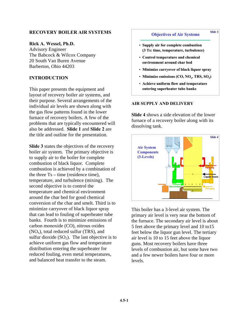
AIR SUPPLY AND DELIVERY Slide 4 shows a side elevation of the lower furnace of a recovery boiler along with its dissolving tank.
Slide 4
Air SystemAir SystemComponentsComponents(3(3--Levels)Levels)
PrimaryPrimarySecondarySecondary
Liquor GunsLiquor Guns
TertiaryTertiary
This boiler has a 3-level air system. The primary air level is very near the bottom of the furnace. The secondary air level is about 5 feet above the primary level and 10 to15 feet below the liquor gun level. The tertiary air level is 10 to 15 feet above the liquor guns. Most recovery boilers have three levels of combustion air, but some have two and a few newer boilers have four or more levels.
4.5-2
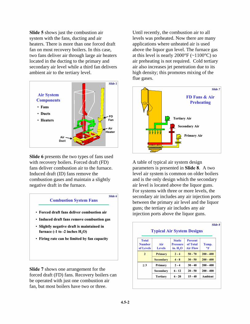
Slide 5 shows just the combustion air system with the fans, ducting and air heaters. There is more than one forced draft fan on most recovery boilers. In this case, two fans deliver air through large air heaters located in the ducting to the primary and secondary air level while a third fan delivers ambient air to the tertiary level.
Slide 5
Air SystemAir SystemComponentsComponents•• FansFans
•• DuctsDucts
•• HeatersHeatersFDFan
AirHeater
AirDuct
Slide 6 presents the two types of fans used with recovery boilers. Forced draft (FD) fans deliver combustion air to the furnace. Induced draft (ID) fans remove the combustion gases and maintain a slightly negative draft in the furnace.
Slide 6Combustion System FansCombustion System Fans
•• Forced draft fans deliver combustion airForced draft fans deliver combustion air
•• Induced draft fans remove combustion gasInduced draft fans remove combustion gas
•• Slightly negative draft is maintained in Slightly negative draft is maintained in furnace (furnace (--1 to 1 to --2 inches H2 inches H22O) O)
•• Firing rate can be limited by fan capacityFiring rate can be limited by fan capacity
Slide 7 shows one arrangement for the forced draft (FD) fans. Recovery boilers can be operated with just one combustion air fan, but most boilers have two or three.
Until recently, the combustion air to all levels was preheated. Now there are many applications where unheated air is used above the liquor gun level. The furnace gas at this level is nearly 2000°F (~1100°C) so air preheating is not required. Cold tertiary air also increases jet penetration due to its high density; this promotes mixing of the flue gases.
Slide 7
FD Fans & AirFD Fans & AirPreheatingPreheating
Tertiary AirTertiary Air
Secondary AirSecondary Air
Primary AirPrimary Air
A table of typical air system design parameters is presented in Slide 8. A two level air system is common on older boilers and is the only design which the secondary air level is located above the liquor guns. For systems with three or more levels, the secondary air includes any air injection ports between the primary air level and the liquor guns; the tertiary air includes any air injection ports above the liquor guns.
Slide 8
Typical Air System DesignsTypical Air System Designs
AmbientAmbient15 15 -- 40406 6 -- 2020TertiaryTertiary
200 200 -- 40040020 20 -- 50506 6 -- 1212SecondarySecondary
200 200 -- 40040030 30 -- 40402 2 -- 44PrimaryPrimary≥≥ 33
200 200 -- 40040030 30 -- 50504 4 -- 88SecondarySecondary
200 200 -- 40040050 50 -- 70702 2 -- 44PrimaryPrimary22
Temp.Temp.°°FF
PercentPercentof Totalof TotalAir FlowAir Flow
StaticStaticPressure Pressure in. Hin. H22OO
AirAirLevelsLevels
Total Total NumberNumberof Levelsof Levels
4.5-3
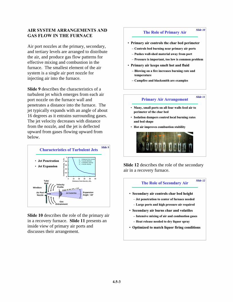
AIR SYSTEM ARRANGEMENTS AND GAS FLOW IN THE FURNACE Air port nozzles at the primary, secondary, and tertiary levels are arranged to distribute the air, and produce gas flow patterns for effective mixing and combustion in the furnace. The smallest element of the air system is a single air port nozzle for injecting air into the furnace. Slide 9 describes the characteristics of a turbulent jet which emerges from each air port nozzle on the furnace wall and penetrates a distance into the furnace. The jet typically expands with an angle of about 16 degrees as it entrains surrounding gases. The jet velocity decreases with distance from the nozzle, and the jet is deflected upward from gases flowing upward from below.
Slide 9
0
0.2
0.4
0.6
0.8
1
0 10 20 30 40 50Distrance from Nozzle, z/Dn
Cen
terli
ne V
eloc
ity,
Vc/
Vn
Characteristics of Turbulent JetsCharacteristics of Turbulent Jets
•• Jet PenetrationJet Penetration
•• Jet ExpansionJet Expansion
GasEntrainment
TubeWall Velocity
ProfileWindbox
Jet CenterlineAir PortNozzle
ExpansionAngle ~16°
z = distance from nozzleDn = nozzle diameterVc = centerline velocityVn = nozzle velocity
Edge of Jet, V/Vc = 0.2
Slide 10 describes the role of the primary air in a recovery furnace. Slide 11 presents an inside view of primary air ports and discusses their arrangement.
Slide 10The Role of Primary AirThe Role of Primary Air
•• Primary air controls the char bed perimeterPrimary air controls the char bed perimeter–– Controls bed burning near primary air portsControls bed burning near primary air ports
–– Pushes wallPushes wall--shed material away from portshed material away from port
–– Pressure is important, too low is common problemPressure is important, too low is common problem
•• Primary air keeps smelt hot and fluidPrimary air keeps smelt hot and fluid–– Blowing on a fire increases burning rate and Blowing on a fire increases burning rate and
temperaturetemperature
–– Campfire and blacksmith are examplesCampfire and blacksmith are examples
Slide 11
Primary Air ArrangementPrimary Air Arrangement
•• Many, small ports on all four walls feed air to Many, small ports on all four walls feed air to perimeter of the char bedperimeter of the char bed
•• Isolation dampers control local burning rates Isolation dampers control local burning rates and bed shapeand bed shape
•• Hot air improves combustion stabilityHot air improves combustion stability
Slide 12 describes the role of the secondary air in a recovery furnace.
Slide 12The Role of Secondary AirThe Role of Secondary Air
•• Secondary air controls char bed heightSecondary air controls char bed height–– Jet penetration to center of furnace neededJet penetration to center of furnace needed
–– Large ports and high pressure air Large ports and high pressure air requiredrequired
•• Secondary air burns char and volatilesSecondary air burns char and volatiles–– Intensive mixing of air and combustion gasesIntensive mixing of air and combustion gases
–– Heat release needed to dry liquor sprayHeat release needed to dry liquor spray
•• Optimized to match liquor firing conditionsOptimized to match liquor firing conditions
4.5-4
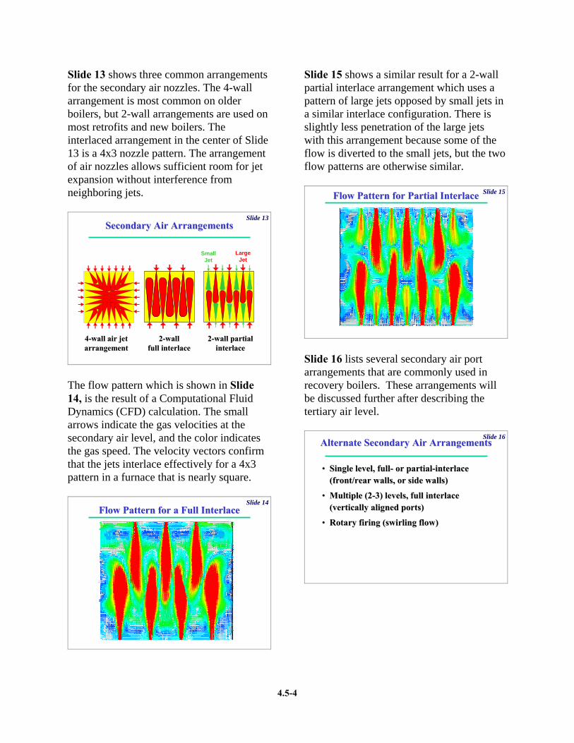
Slide 13 shows three common arrangements for the secondary air nozzles. The 4-wall arrangement is most common on older boilers, but 2-wall arrangements are used on most retrofits and new boilers. The interlaced arrangement in the center of Slide 13 is a 4x3 nozzle pattern. The arrangement of air nozzles allows sufficient room for jet expansion without interference from neighboring jets.
Slide 13Secondary Air ArrangementsSecondary Air Arrangements
44--wall air jetwall air jetarrangementarrangement
22--wallwallfull interlacefull interlace
22--wall partialwall partialinterlaceinterlace
SmallJet
LargeJet
The flow pattern which is shown in Slide 14, is the result of a Computational Fluid Dynamics (CFD) calculation. The small arrows indicate the gas velocities at the secondary air level, and the color indicates the gas speed. The velocity vectors confirm that the jets interlace effectively for a 4x3 pattern in a furnace that is nearly square.
Slide 14Flow Pattern for a Full InterlaceFlow Pattern for a Full Interlace
Slide 15 shows a similar result for a 2-wall partial interlace arrangement which uses a pattern of large jets opposed by small jets in a similar interlace configuration. There is slightly less penetration of the large jets with this arrangement because some of the flow is diverted to the small jets, but the two flow patterns are otherwise similar.
Slide 15Flow Pattern for Partial InterlaceFlow Pattern for Partial Interlace
Slide 16 lists several secondary air port arrangements that are commonly used in recovery boilers. These arrangements will be discussed further after describing the tertiary air level.
Slide 16Alternate Secondary Air ArrangementsAlternate Secondary Air Arrangements
•• Single level, fullSingle level, full-- or partialor partial--interlace interlace (front/rear walls, or side walls)(front/rear walls, or side walls)
•• Multiple (2Multiple (2--3) levels, full interlace 3) levels, full interlace (vertically aligned ports)(vertically aligned ports)
•• Rotary firing (swirling flow)Rotary firing (swirling flow)

4.5-5
Slide 17 describes the role of the tertiary air in a recovery furnace. Reducing conditions in the lower furnace improve smelt reduction and reduce NOx emissions. Oxidizing conditions in the upper furnace reduce CO and TRS emissions and minimize corrosion of furnace wall tubes.
Slide 17The Role of Tertiary AirThe Role of Tertiary Air
•• Tertiary air completes mixing and burning Tertiary air completes mixing and burning of combustible gases (CO, Hof combustible gases (CO, H22S, etc.)S, etc.)–– Jet penetration to center of furnace neededJet penetration to center of furnace needed
–– Large ports with high pressure air requiredLarge ports with high pressure air required
•• Tertiary air is essential for staged Tertiary air is essential for staged combustioncombustion–– Reducing conditions in lower furnaceReducing conditions in lower furnace
–– Oxidizing conditions in upper furnaceOxidizing conditions in upper furnace
Slide 18 shows two air nozzle arrangements at the tertiary air level. The interlace pattern here is a 4x3 configuration. This pattern, or a 5x4 pattern, is typically used at the tertiary level. The concentric tertiary air on the right is a modification of a tangential pattern used by one vendor; this produces rotating gas flow in the upper furnace and is known to cause and unbalanced flow and temperature distribution entering the superheater. The interlaced arrangement produces more balanced conditions in the upper furnace.
Slide 18Tertiary Air ArrangementsTertiary Air Arrangements
Interlaced Tertiary AirInterlaced Tertiary Air Concentric Tertiary AirConcentric Tertiary Air
Slide 19 lists several tertiary air port arrangements that are commonly used in recovery boilers.
Slide 19Alternate Tertiary Air ArrangementsAlternate Tertiary Air Arrangements
•• Single level, full interlace (front/rear walls)Single level, full interlace (front/rear walls)
•• Multiple (2Multiple (2--4) levels, full interlace 4) levels, full interlace (vertically aligned ports)(vertically aligned ports)
•• Two separate levels, 10 to 20 feet apart Two separate levels, 10 to 20 feet apart (upper most level (upper most level -- quaternary air)quaternary air)
•• Concentric tertiary air, or tangential Concentric tertiary air, or tangential tertiary air (swirling flow)tertiary air (swirling flow)
Newer boiler designs and retrofits have demonstrated certain advantages for more than 3 levels of air, particularly for units firing high solids liquor. As previously mentioned, multiple air levels can be used to supply secondary air, tertiary air, or both. Slide 20 lists the advantages of multi-level air systems and cautions that these designs may promote combustion instability on the char bed or corrosion in the upper furnace.
Slide 20MultiMulti--level Air Systemslevel Air Systems
•• Advantages of multiAdvantages of multi--level secondary and level secondary and tertiary air systemstertiary air systems–– Reduced fouling by carryoverReduced fouling by carryover–– Better mixing and emissions controlBetter mixing and emissions control
•• Potential disadvantagesPotential disadvantages–– Difficult to control char bed combustionDifficult to control char bed combustion
at lowat low--medium solidsmedium solids–– Accelerated corrosion by reducing gases Accelerated corrosion by reducing gases
reaching above composite tube linereaching above composite tube line
4.5-6
Slide 21 describes how an air system arrangement is selected for a particular boiler design and operation. Any one combination of the previously described arrangements may not work on all boilers.
Slide 21Selecting An ArrangementSelecting An Arrangement
•• The best arrangement depends on The best arrangement depends on furnace design, liquor properties, furnace design, liquor properties, spray conditions, and firing ratespray conditions, and firing rate
•• Arrangement is optimized by CFD and Arrangement is optimized by CFD and combustion modelingcombustion modeling
•• Performance is demonstrated by field Performance is demonstrated by field testing and operating experiencetesting and operating experience
Engineers must consider the boiler design, liquor properties, spray conditions and firing rate to determine the best arrangement. CFD and combustion modeling of the recovery furnace is the most common approach to optimize the air system arrangement. Field testing and operating experience is the ultimately the most reliable means to demonstrate air system performance. AIR SYSTEM PROBLEMS Two of the problems encountered with recovery boiler air systems are their inflexibility once installed, and their need for frequent port cleaning. This is described in Slide 22.
Slide 22Air System Operating ProblemsAir System Operating Problems
•• Air delivery systems are inflexibleAir delivery systems are inflexible–– ΔΔP proportional to square of flowP proportional to square of flow
–– Limits recovery boiler turndownLimits recovery boiler turndown
–– Port velocity control dampers increase Port velocity control dampers increase flexibilityflexibility
•• Air ports need frequent cleaningAir ports need frequent cleaning–– Automatic port rodders improve performanceAutomatic port rodders improve performance
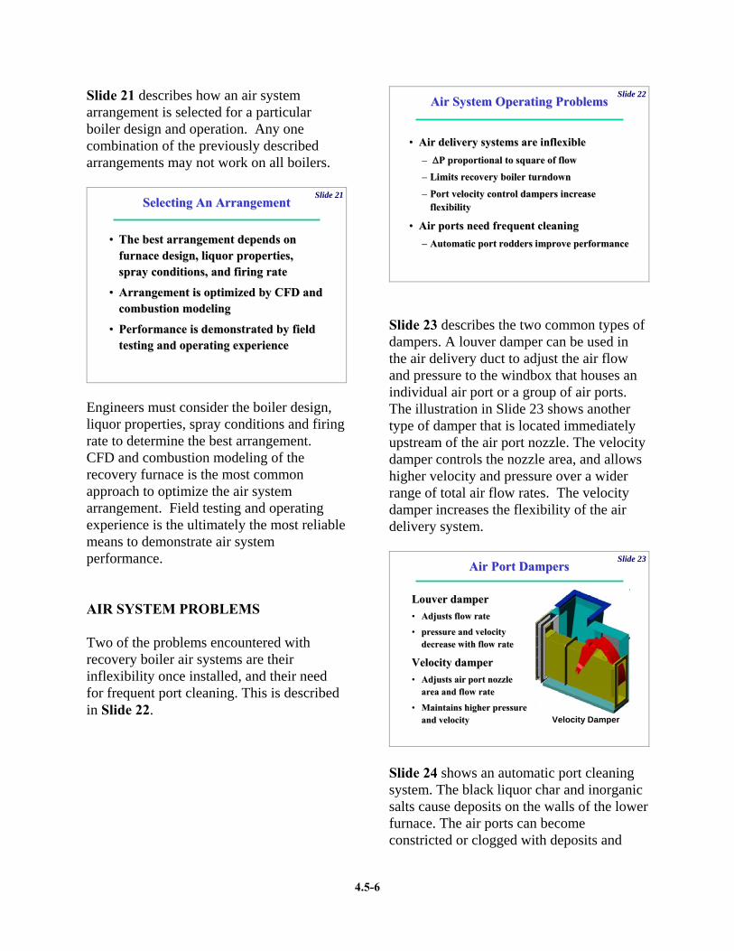
Slide 23 describes the two common types of dampers. A louver damper can be used in the air delivery duct to adjust the air flow and pressure to the windbox that houses an individual air port or a group of air ports. The illustration in Slide 23 shows another type of damper that is located immediately upstream of the air port nozzle. The velocity damper controls the nozzle area, and allows higher velocity and pressure over a wider range of total air flow rates. The velocity damper increases the flexibility of the air delivery system.
Slide 23Air Port DampersAir Port Dampers
Louver damperLouver damper•• Adjusts flow rateAdjusts flow rate
•• pressure and velocity pressure and velocity decrease with flow ratedecrease with flow rate
Velocity damperVelocity damper•• Adjusts air port nozzleAdjusts air port nozzle
area and flow ratearea and flow rate
•• Maintains higher pressure Maintains higher pressure and velocityand velocity Velocity DamperVelocity Damper
Slide 24 shows an automatic port cleaning system. The black liquor char and inorganic salts cause deposits on the walls of the lower furnace. The air ports can become constricted or clogged with deposits and
4.5-7
must be cleaned periodically. The traditional method is hand rodding of the ports. The diagram in Slide 24 illustrates one of several designs for cleaning the ports automatically.
Slide 24Automatic Port CleaningAutomatic Port Cleaning
ExtendedExtended
Retracted
There are several other potential design problems with recovery boiler air systems. These are described in Slide 25.
Slide 25Air System Design ProblemsAir System Design Problems
•• Insufficient fan capacity for increased loadsInsufficient fan capacity for increased loads
•• Duct size, length, and bends can limit flowDuct size, length, and bends can limit flow
•• Duct flow is not always uniformDuct flow is not always uniform
•• Duct arrangement can affect nozzle flowDuct arrangement can affect nozzle flow
•• Boiler supports limit duct/nozzle placementBoiler supports limit duct/nozzle placement
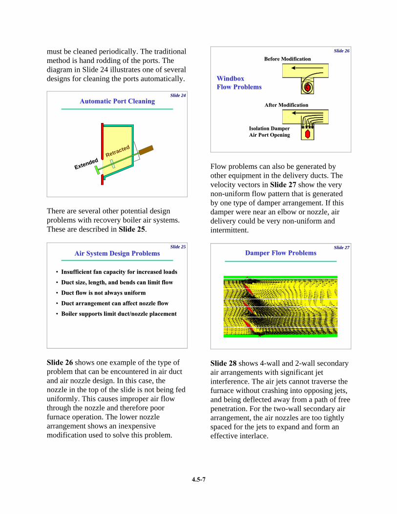
Slide 26 shows one example of the type of problem that can be encountered in air duct and air nozzle design. In this case, the nozzle in the top of the slide is not being fed uniformly. This causes improper air flow through the nozzle and therefore poor furnace operation. The lower nozzle arrangement shows an inexpensive modification used to solve this problem.
Slide 26
WindboxWindboxFlow ProblemsFlow Problems
Isolation DamperIsolation DamperAir Port OpeningAir Port Opening
Before ModificationBefore Modification
After ModificationAfter Modification
Flow problems can also be generated by other equipment in the delivery ducts. The velocity vectors in Slide 27 show the very non-uniform flow pattern that is generated by one type of damper arrangement. If this damper were near an elbow or nozzle, air delivery could be very non-uniform and intermittent.
Slide 27Damper Flow ProblemsDamper Flow Problems
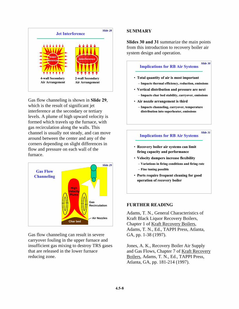
Slide 28 shows 4-wall and 2-wall secondary air arrangements with significant jet interference. The air jets cannot traverse the furnace without crashing into opposing jets, and being deflected away from a path of free penetration. For the two-wall secondary air arrangement, the air nozzles are too tightly spaced for the jets to expand and form an effective interlace.
4.5-8
Slide 28
44--wall Secondarywall SecondaryAir ArrangementAir Arrangement
Jet InterferenceJet Interference
22--wall Secondarywall SecondaryAir ArrangementAir Arrangement
InterferenceInter-
ference
Gas flow channeling is shown in Slide 29, which is the result of significant jet interference at the secondary or tertiary levels. A plume of high upward velocity is formed which travels up the furnace, with gas recirculation along the walls. This channel is usually not steady, and can move around between the center and any of the corners depending on slight differences in flow and pressure on each wall of the furnace.
Slide 29
Gas FlowGas FlowChannelingChanneling
Air NozzlesChar bed
GasRecirculation
HighVelocityPlume
Gas flow channeling can result in severe carryover fouling in the upper furnace and insufficient gas mixing to destroy TRS gases that are released in the lower furnace reducing zone.
SUMMARY Slides 30 and 31 summarize the main points from this introduction to recovery boiler air system design and operation.
Slide 30Implications for RB Air SystemsImplications for RB Air Systems
•• Total quantity of air is most importantTotal quantity of air is most important–– Impacts thermal efficiency, reduction, emissionsImpacts thermal efficiency, reduction, emissions
•• Vertical distribution and pressure are nextVertical distribution and pressure are next–– Impacts char bed stability, carryover, emissionsImpacts char bed stability, carryover, emissions
•• Air nozzle arrangement is thirdAir nozzle arrangement is third–– Impacts channeling, carryover, temperature Impacts channeling, carryover, temperature
distribution into superheater, emissionsdistribution into superheater, emissions
Slide 31
Implications for RB Air SystemsImplications for RB Air Systems
•• Recovery boiler air systems can limit Recovery boiler air systems can limit firing capacity and performancefiring capacity and performance
•• Velocity dampers increase flexibilityVelocity dampers increase flexibility–– Variations in firing conditions and firing rateVariations in firing conditions and firing rate
–– Fine tuning possibleFine tuning possible
•• Ports require frequent cleaning for good Ports require frequent cleaning for good operation of recovery boileroperation of recovery boiler
FURTHER READING
Adams, T. N., General Characteristics of Kraft Black Liquor Recovery Boilers, Chapter 1 of Kraft Recovery Boilers, Adams, T. N., Ed., TAPPI Press, Atlanta, GA, pp. 1-38 (1997). Jones, A. K., Recovery Boiler Air Supply and Gas Flows, Chapter 7 of Kraft Recovery Boilers, Adams, T. N., Ed., TAPPI Press, Atlanta, GA, pp. 181-214 (1997).