Embed Size (px)
Citation preview
Recovering Stereo Pairs from Anaglyphs
Armand JoulinINRIA/Ecole Normale Superieure1
Sing Bing KangMicrosoft Research
Abstract
An anaglyph is a single image created by selecting com-plementary colors from a stereo color pair; the user canperceive depth by viewing it through color-filtered glasses.We propose a technique to reconstruct the original colorstereo pair given such an anaglyph. We modified SIFT-Flowand use it to initially match the different color channelsacross the two views. Our technique then iteratively refinesthe matches, selects the good matches (which defines the“anchor” colors), and propagates the anchor colors. Weuse a diffusion-based technique for the color propagation,and added a step to suppress unwanted colors. Results ona variety of inputs demonstrate the robustness of our tech-nique. We also extended our method to anaglyph videos byusing optic flow between time frames.
1. IntroductionArguably, the first 3D motion picture was shown in
1889 by William Friese-Green, who used the separation of
colors from the stereo pair to generate color composites.
Glasses with appropriate color filters are used to perceive
the depth effect. Such images generated by color separation
are called anaglyphs. An example is shown in top-left part
of Figure 1, where the color separation is red-cyan. Here,
anaglyph glasses comprising red-cyan filters are used to per-
ceive depth. There is much legacy anaglyph content avail-
able with no original color pairs.
In this paper, we show how we can reliably reconstruct
a good approximation of the original color stereo pair given
its anaglyph. We assume the left-right color separation is
red-cyan, which is the most common; the principles of our
technique can be applied to other color separation schemes.
Given an anaglyph, recovering the stereo color pair is
equivalent to transferring the intensities in the red channel
to the right image and the intensities in the blue and green
channels to the left one. Unfortunately, the intensity distri-
butions between the three channels are usually very differ-
1WILLOW project-team, Laboratoire d’Informatique de l’Ecole Nor-
male Superieure, ENS/INRIA UMR 8548.
ent, with mappings of intensities typically being many-to-
many. This complicates the use of stereo and standard color
transfer methods. Since the input is essentially a stereo pair,
we have to handle occlusions as well.
Our technical contributions are as follow:
• A completely automatic technique for reconstructing
the stereo pair from an anaglyph (image or video).
• Non-trivial extensions to SIFT-Flow [14] to handle
registration across color channels.
• Non-trivial extensions to Levin et al.’s [11] coloriza-
tion technique to handle diffusion of only specific
color channels per view, and use of longer range influ-
ence. We also added the step of suppressing visually
inappropriate colors at disocclusions.
We made the following assumptions:
• There are no new colors in the disoccluded regions.
• The information embedded in the anaglyph is enough
to reconstruct full rgb2.
• The images are roughly rectified (with epipolar devia-
tion of up to ±25 pixels).
As we demonstrate through a variety of results, our tech-
nique is robust to inadvertent asymmetric occlusion in one
camera (e.g., part of a finger in one view but not in the other)
as well as blurry and low-light scenes.
2. Related workAs far as we know, there are two approaches for generat-
ing stereo pairs from anaglyphs. The first is a tool called
Deanaglyph3. However, it requires as input not just the
anaglyph, but also one color image. Dietz [3] proposed a
method to recover the original images from anaglyphs cap-
tured using a modified camera with color filters. There is
unfortunately insufficient information in the paper on how
his technique works; however, his results show that the col-
ors often do not match across the reconstructed stereo pair.
2Certain types of anaglyphs, such as the “optimized” anaglyph, throws
away the red channel; it fakes the red channel of the left image by combin-
ing green and blue channels.3http://www.3dtv.at/Knowhow/DeAnaglyph_en.aspx
2013 IEEE Conference on Computer Vision and Pattern Recognition
1063-6919/13 $26.00 © 2013 IEEE
DOI 10.1109/CVPR.2013.44
289
2013 IEEE Conference on Computer Vision and Pattern Recognition
1063-6919/13 $26.00 © 2013 IEEE
DOI 10.1109/CVPR.2013.44
289
2013 IEEE Conference on Computer Vision and Pattern Recognition
1063-6919/13 $26.00 © 2013 IEEE
DOI 10.1109/CVPR.2013.44
289
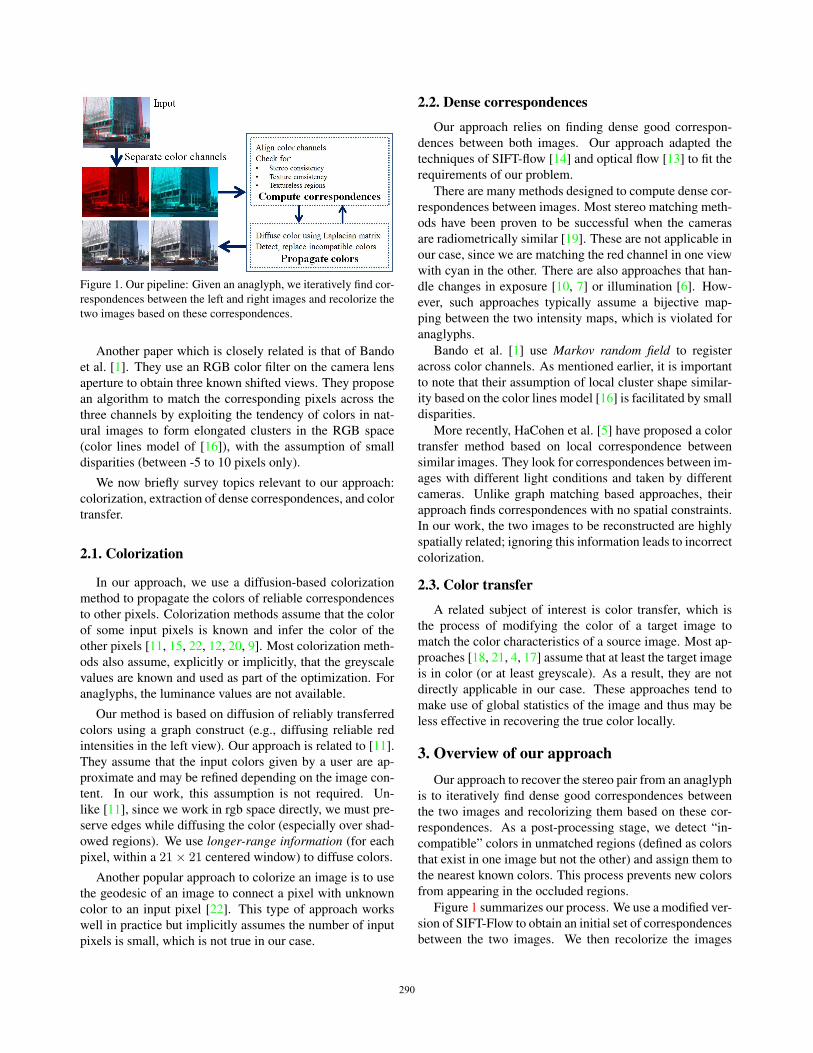
Figure 1. Our pipeline: Given an anaglyph, we iteratively find cor-
respondences between the left and right images and recolorize the
two images based on these correspondences.
Another paper which is closely related is that of Bando
et al. [1]. They use an RGB color filter on the camera lens
aperture to obtain three known shifted views. They propose
an algorithm to match the corresponding pixels across the
three channels by exploiting the tendency of colors in nat-
ural images to form elongated clusters in the RGB space
(color lines model of [16]), with the assumption of small
disparities (between -5 to 10 pixels only).
We now briefly survey topics relevant to our approach:
colorization, extraction of dense correspondences, and color
transfer.
2.1. Colorization
In our approach, we use a diffusion-based colorization
method to propagate the colors of reliable correspondences
to other pixels. Colorization methods assume that the color
of some input pixels is known and infer the color of the
other pixels [11, 15, 22, 12, 20, 9]. Most colorization meth-
ods also assume, explicitly or implicitly, that the greyscale
values are known and used as part of the optimization. For
anaglyphs, the luminance values are not available.
Our method is based on diffusion of reliably transferred
colors using a graph construct (e.g., diffusing reliable red
intensities in the left view). Our approach is related to [11].
They assume that the input colors given by a user are ap-
proximate and may be refined depending on the image con-
tent. In our work, this assumption is not required. Un-
like [11], since we work in rgb space directly, we must pre-
serve edges while diffusing the color (especially over shad-
owed regions). We use longer-range information (for each
pixel, within a 21× 21 centered window) to diffuse colors.
Another popular approach to colorize an image is to use
the geodesic of an image to connect a pixel with unknown
color to an input pixel [22]. This type of approach works
well in practice but implicitly assumes the number of input
pixels is small, which is not true in our case.
2.2. Dense correspondences
Our approach relies on finding dense good correspon-
dences between both images. Our approach adapted the
techniques of SIFT-flow [14] and optical flow [13] to fit the
requirements of our problem.
There are many methods designed to compute dense cor-
respondences between images. Most stereo matching meth-
ods have been proven to be successful when the cameras
are radiometrically similar [19]. These are not applicable in
our case, since we are matching the red channel in one view
with cyan in the other. There are also approaches that han-
dle changes in exposure [10, 7] or illumination [6]. How-
ever, such approaches typically assume a bijective map-
ping between the two intensity maps, which is violated for
anaglyphs.
Bando et al. [1] use Markov random field to register
across color channels. As mentioned earlier, it is important
to note that their assumption of local cluster shape similar-
ity based on the color lines model [16] is facilitated by small
disparities.
More recently, HaCohen et al. [5] have proposed a color
transfer method based on local correspondence between
similar images. They look for correspondences between im-
ages with different light conditions and taken by different
cameras. Unlike graph matching based approaches, their
approach finds correspondences with no spatial constraints.
In our work, the two images to be reconstructed are highly
spatially related; ignoring this information leads to incorrect
colorization.
2.3. Color transfer
A related subject of interest is color transfer, which is
the process of modifying the color of a target image to
match the color characteristics of a source image. Most ap-
proaches [18, 21, 4, 17] assume that at least the target image
is in color (or at least greyscale). As a result, they are not
directly applicable in our case. These approaches tend to
make use of global statistics of the image and thus may be
less effective in recovering the true color locally.
3. Overview of our approachOur approach to recover the stereo pair from an anaglyph
is to iteratively find dense good correspondences between
the two images and recolorizing them based on these cor-
respondences. As a post-processing stage, we detect “in-
compatible” colors in unmatched regions (defined as colors
that exist in one image but not the other) and assign them to
the nearest known colors. This process prevents new colors
from appearing in the occluded regions.
Figure 1 summarizes our process. We use a modified ver-
sion of SIFT-Flow to obtain an initial set of correspondences
between the two images. We then recolorize the images
290290290
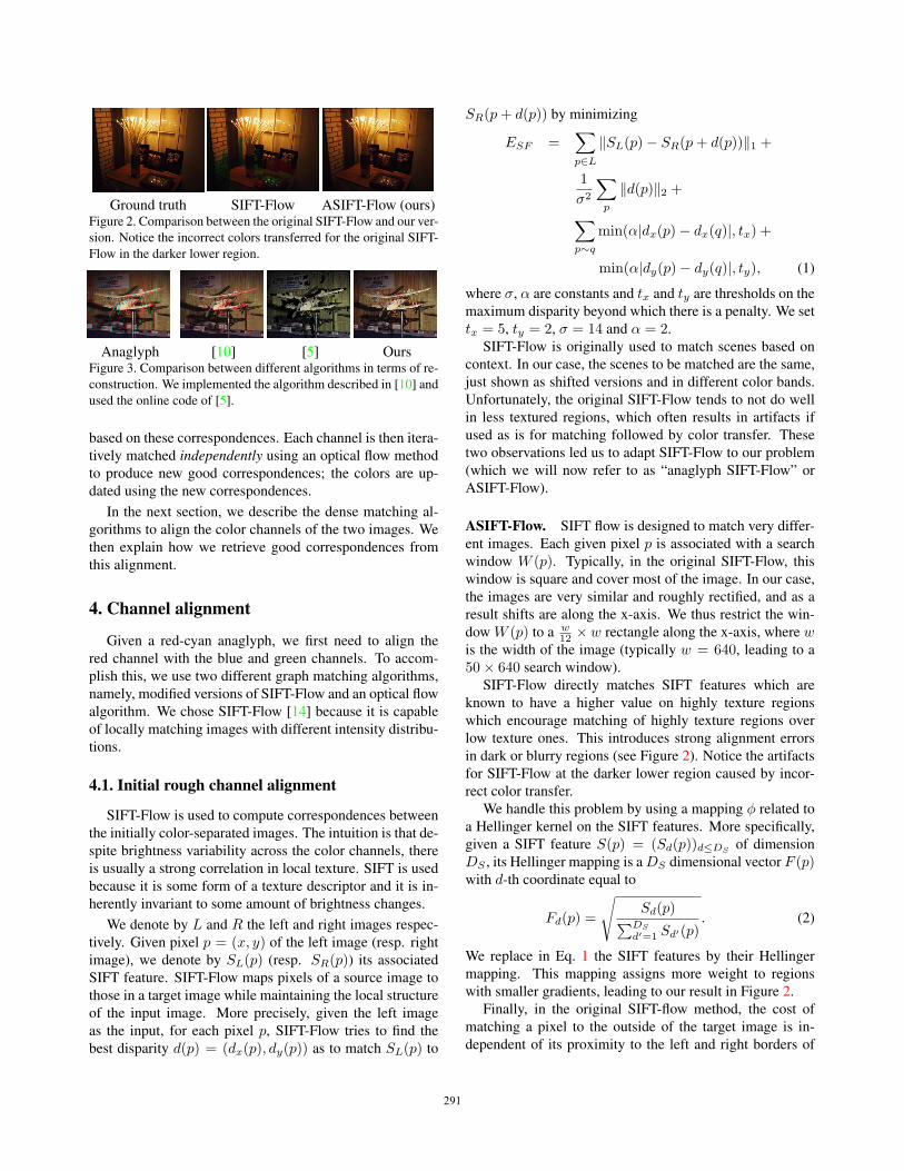
Ground truth SIFT-Flow ASIFT-Flow (ours)Figure 2. Comparison between the original SIFT-Flow and our ver-
sion. Notice the incorrect colors transferred for the original SIFT-
Flow in the darker lower region.
Anaglyph [10] [5] OursFigure 3. Comparison between different algorithms in terms of re-
construction. We implemented the algorithm described in [10] and
used the online code of [5].
based on these correspondences. Each channel is then itera-
tively matched independently using an optical flow method
to produce new good correspondences; the colors are up-
dated using the new correspondences.
In the next section, we describe the dense matching al-
gorithms to align the color channels of the two images. We
then explain how we retrieve good correspondences from
this alignment.
4. Channel alignment
Given a red-cyan anaglyph, we first need to align the
red channel with the blue and green channels. To accom-
plish this, we use two different graph matching algorithms,
namely, modified versions of SIFT-Flow and an optical flow
algorithm. We chose SIFT-Flow [14] because it is capable
of locally matching images with different intensity distribu-
tions.
4.1. Initial rough channel alignment
SIFT-Flow is used to compute correspondences between
the initially color-separated images. The intuition is that de-
spite brightness variability across the color channels, there
is usually a strong correlation in local texture. SIFT is used
because it is some form of a texture descriptor and it is in-
herently invariant to some amount of brightness changes.
We denote by L and R the left and right images respec-
tively. Given pixel p = (x, y) of the left image (resp. right
image), we denote by SL(p) (resp. SR(p)) its associated
SIFT feature. SIFT-Flow maps pixels of a source image to
those in a target image while maintaining the local structure
of the input image. More precisely, given the left image
as the input, for each pixel p, SIFT-Flow tries to find the
best disparity d(p) = (dx(p), dy(p)) as to match SL(p) to
SR(p+ d(p)) by minimizing
ESF =∑p∈L
‖SL(p)− SR(p+ d(p))‖1 +
1
σ2
∑p
‖d(p)‖2 +∑p∼q
min(α|dx(p)− dx(q)|, tx) +
min(α|dy(p)− dy(q)|, ty), (1)
where σ, α are constants and tx and ty are thresholds on the
maximum disparity beyond which there is a penalty. We set
tx = 5, ty = 2, σ = 14 and α = 2.
SIFT-Flow is originally used to match scenes based on
context. In our case, the scenes to be matched are the same,
just shown as shifted versions and in different color bands.
Unfortunately, the original SIFT-Flow tends to not do well
in less textured regions, which often results in artifacts if
used as is for matching followed by color transfer. These
two observations led us to adapt SIFT-Flow to our problem
(which we will now refer to as “anaglyph SIFT-Flow” or
ASIFT-Flow).
ASIFT-Flow. SIFT flow is designed to match very differ-
ent images. Each given pixel p is associated with a search
window W (p). Typically, in the original SIFT-Flow, this
window is square and cover most of the image. In our case,
the images are very similar and roughly rectified, and as a
result shifts are along the x-axis. We thus restrict the win-
dow W (p) to a w12 ×w rectangle along the x-axis, where w
is the width of the image (typically w = 640, leading to a
50× 640 search window).
SIFT-Flow directly matches SIFT features which are
known to have a higher value on highly texture regions
which encourage matching of highly texture regions over
low texture ones. This introduces strong alignment errors
in dark or blurry regions (see Figure 2). Notice the artifacts
for SIFT-Flow at the darker lower region caused by incor-
rect color transfer.
We handle this problem by using a mapping φ related to
a Hellinger kernel on the SIFT features. More specifically,
given a SIFT feature S(p) = (Sd(p))d≤DSof dimension
DS , its Hellinger mapping is a DS dimensional vector F (p)with d-th coordinate equal to
Fd(p) =
√Sd(p)∑DS
d′=1 Sd′(p). (2)
We replace in Eq. 1 the SIFT features by their Hellinger
mapping. This mapping assigns more weight to regions
with smaller gradients, leading to our result in Figure 2.
Finally, in the original SIFT-flow method, the cost of
matching a pixel to the outside of the target image is in-
dependent of its proximity to the left and right borders of
291291291
the image. In other terms, SIFT-Flow penalize the match-
ing of a pixel p to the outside by a constant cost K. In our
case, since we expect our image pair to be roughly rectified,
disparity is mostly horizontal. As such, we penalize vertical
shifts as well as based on the amount of deviation from the
left or right borders. More precisely, given a pixel p at a
L1 distance d(p) to the closest border, we replace the con-
stant cost K by a cost depending on this distance, namely,
Kd(p).
Comparison with other matching methods. Why did
we use ASIFT-Flow and not other methods? In particular,
Kim et al. [10] propose a stereo matching algorithm which
works for images with different intensity distribution. How-
ever, they assume that the mapping of intensity levels is one-
to-one, which is not true in general between color channels.
HaCohen et al. [5] recover the various textures of the image
but is not robust enough to deal with high intensity changes
resulting in wrong color estimations. We find that these two
approaches do not work as well as ASIFT-Flow; a represen-
tative example is shown in Figure 3.
SIFT is computed on 16 × 16 patches; its coarseness is
why we use it only to obtain a first rough alignment in the
initialization. In the next section, we explain how we refine
the channel alignment.
4.2. Refining channel alignment
Using the matches by ASIFT-Flow, we have a first rough
colorization of the two images. In many cases, the re-
sults look reasonable. However, artifacts can occur in areas
with significant lighting and/or texture changes. In addi-
tion, since ASIFT-Flow is block-based, artifacts are usually
generated at object boundaries.
Unfortunately, since the color reconstruction is still only
approximate, image rectification may only be approximate
as well. As a result, we allow for some slop in the vertical
direction when refining the search, and we use optical flow.
Note that our problem is not that of stereo, but rather color
reconstruction. We compute optical flow independently on
the three channels, namely, the red channel for the left im-
age and the blue and green channels for the right image.
While some of the re-estimated matches are better, errors
still occur. In the next section, we describe a criteria to se-
lect the good matches.
5. Finding good matchesGiven matches from left to right ML �→R and those from
right to left MR �→L, different criteria can be used to se-
lect the more reliable ones. We use three different crite-
ria: stereo consistency, texture consistency, and detection
of textureless regions. These criteria are based on compar-
ing an original known channel with its reprojected (warped)
version (ML �→R and MR �→L).
Stereo consistency (or match reciprocity). This refers
to the property that for a pair of correspondences, in each
direction, the corresponding pixel is the best choice. In
other words, given a pixel i in the left image, we say
that it is a good match wrt stereo consistency if i ==MR �→L
(ML �→R(i)
).
Since the imprecision in SIFT matching at the pixel level
makes it difficult to satisfy this criterion exactly, we use a
soft version where a pixel is allow to match a pixel within a
tx × ty (= 5× 2) window. The modified criteria are
|x(i)− x(MR �→L
(ML �→R(i)
))| ≤ tx, (3)
|y(i)− y(MR �→L
(ML �→R(i)
))| ≤ ty. (4)
Texture consistency. A match is good if its reprojected
(warped) value is similar to the observed. In this case,
we are comparing SIFT features: original observed S(p)and reprojected S(p). The match is deemed good the
distance between the two features is small enough, i.e.,
|S(p)− S(p)| < ts. Typically, we fix ts = 2.
Textureless regions. Textureless regions are a special
case, since both our rough and refined alignment steps tend
to fail there. We define a pixel to be “textureless” if its as-
sociated SIFT feature has a norm below a certain threshold
(set to 1). A match is deemed good if both pixels are tex-
tureless.
The criteria allow us to select good candidate matches.
We make the strong assumption that the reconstructed col-
ors (anchor colors) using these matches is correct. Our goal
is now to propagate anchor colors to the other pixels, which
is the colorization step.
6. ColorizationThere are many approaches for colorization [8, 22, 11,
2]. The most popular are either based on diffusion [11] or
geodesic distance [22]. We did not consider methods based
on geodesic distance because they are not suitable for cases
where the number of anchor pixels (i.e., good matches in
our case) is very high. Based on our experiments, they oc-
cupy between 80-90% of the image.
In this section, we describe a colorization method in-
spired by Levin et al. [11]; non-trivial modifications are
necessary to adapt to our unique problem formulation.
6.1. Diffusion method
In Levin et al. [11], given a greyscale image, a similarity
matrix W between nearby pixels is constructed, from which
a diagonal matrix D containing the sum of each row of Wand a normalized Laplacian matrix L = I − D−1W are
computed and used for color diffusion. Denoting by I(i)the intensity of a given pixel, we use W with entry Wij
292292292
being zero if the two pixels i and j are not within 10 pixels
of each other; otherwise it is
Wij = exp(−γ‖I(i)− I(j)‖22)δ(‖I(i)− I(j)‖1 ≤ λI),
where δ is the indicator (membership) function and λI is a
fixed threshold set to 25. The anchor colors (yk, “known”)
are fixed, with the rest (yu, “unknown”) needed to be com-
puted. Let Luu (resp. Luk) be the sub-block matrix of Lwith row and column indexed by the unknown pixels (re-
spectively unknown and known pixels). We solve
minyu∈[0,1]
1
2(yTuLuuyu + 2yuLukyk),
which is equivalent to the following linear problem:
Luuyu = Lukyk.
If Np is the number of unknown pixels, solving the linear
problem is O(N2p ). For most images, Np is small and this
closed form solution is efficiently computed. For large im-
ages or video sequences, Np can be very big and computing
the closed form solution is prohibitive. In those cases, we
reduce the complexity of the algorithm by considering Nr
non-overlapping horizontal bands (we use Nr = 4). This
is guaranteed to converge since the cost function is strongly
convex and the complexity is O(NrNp).
6.2. Differences with Levin et al. [11]
In [11], the user-specified colors may be modified. This
is reasonable, since they are specified via scribbles, which
are only approximate. Their method can be regarded as
a one-step gradient descent with a good initialization. In
addition, their method works in YUV space because the
grayscale image is known. In our case, the grayscale im-
age is unknown, and as such, this color space is not useable.
Finally, our similarity matrix is different. More specifically,
for [11], the similarity function is different and only im-
mediate 4-neighbors are connected. This is justified in the
YUV space but does not work as well in rgb space.
We iterate between colorizing both images and aligning
the channels. At the end of this process, it is possible for
disoccluded regions to have colors not found elsewhere (we
term such colors as “incompatible” colors). In the next sec-
tion, we describe a method to detect such colors and recol-
orize them.
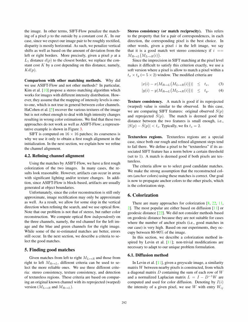
7. Detecting incompatible colorsOur approach uses the anchor colors to fill in the miss-
ing colors. However, objects in disoccluded regions may be
incorrectly colored. As shown in Figure 4, for each scene,
a border region of the leftmost image is unobserved in the
other view, resulting in out-of-place colorization. To detect
Before After Ground truthFigure 4. Examples of recolorization of occluded regions with in-
compatible colors.
such occurrences and subsequently color correct, we make
the assumption that there are no new colors in the occluded
regions in order to produce visually plausible outputs.
To recolorize, we first detect regions with incompatible
colors before we recolorize them with longer range connec-
tions. Let us first consider the right image; the same reason-
ing is applied to the left image. Given pixel p in the right
image with color cp = (rp, gp, bp), the goal is to find if
its estimated red value rp is compatible with the red values
observed in the rest of the image given the same blue and
green values.
While it seems natural to compute P (rp | gp, bp) on
the good matches, the function will not be precise because
the samples are small given the wide range of blue and
green values. In addition, it is not clear how to define a
threshold over the probability values. Instead, we consider
the Nadaraya-Watson kernel regressor to estimate the most
probable red value the pixel p should have given its current
estimate. The estimator is
rNWp =
∑q∈Q
(K(
rp−rqh )∑
q∈QK(rp−rq
h )
)rq, (5)
where K is a kernel with bandwidth h = 0.1 andQ is the set
of good matches with the same blue and green values. We
represent 2552 possible blue and green combinations with
512 bins to reduce space requirements. We use 255 bins for
the red channel.
K is the kernel associated with Gaussian white noise.
Note that the computation of mean-shift superpixels and
non-local mean are also based on this regressor. Pixel pis deemed to be an incompatible color if |rNW
p − rp| is
above a certain threshold λ. In our work, we set λ = 0.3for intensity in the normalized range of 0 to 1. We design
our colorization algorithm with a longer range than that for
diffusion (101 × 101 instead of 21 × 21), and it helps to
substantially reduce coloring artifacts. Two representative
results are shown in the middle column in Figure 4.
293293293
8. ResultsWe ran our experiments on a laptop with a single core
(1.6 GHz) and 2 GB of RAM. The code is that of MATLAB
with certain functions implemented in C++. It takes on av-
erage between 4-10 minutes to process an image (which
is first scaled to 640 × 480). If we only apply the rough
alignment, the colorization and the incompatible color de-
tection (referred as “MSF+col”), the process takes between
2-5 minutes. Note also that this code can be easily paral-
lelized since most of the process are done on the left and
right views independently.
To evaluate the quality of our results, we ran our exper-
iments using stereo images and videos collected over about
two years by one of the authors using FujiFilm FinePix
REAL 3D W1 camera and Aiptek 3D-HD camcorder. Here
we have ground truth, with the anaglyphs synthetically gen-
erated from the stereo pairs. Note that both capture devices
were deliberately not calibrated for this work. We also show
results of our method on images available online (including
those recently taken of Mars); there is no ground truth asso-
ciated with these images.
Comparison with Deanaglyph. This tool was released by
3dtv; it reconstructs the right image given the anaglyph and
the left image. Since Deanaglyph assumes the left image
is known, we show results only for the right image (our al-
gorithm still computes both images) in Figure 5. Note the
visible artifacts generated by Deanaglyph; it also crops out
some amount of the border pixels.
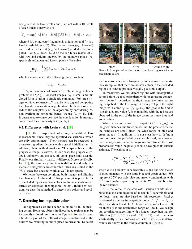
Comparison with Bando et al. [1]. We ran our algorithm
on inputs captured using the camera described in [1] (we
used their image and code to generate their result). Because
the blue and green channels are shifted as well, we matching
the red channel to the blue and green independently. We
then apply the same colorization algorithm. As shown in
Figure 6, we obtained comparable results (though with less
apparent edge artifacts) with the same set of parameters as
used to reconstruct the other anaglyphs.
Quantitative results on our dataset. We use our datasets
(“CityA” with 94 images and “CityB” with 88 images of in-
door and outdoor scenes) to evaluate the effectiveness of
our algorithm. Here we have ground truth, from which
the input anaglyphs are generated and processed. The
quality measure we compute is Peak Signal-to-Noise Ra-
tio (PSNR): Given an image I and its reconstruction I , the
PSNR measure is equal to PSNR = 20 log10(max(I)) −10 log(MSE), where MSE = ‖I − I‖22.
The computed PSNR values of our algorithm are shown
in Table 1. We see that our method performs better than
the baseline. Note that recolorizing occluded regions does
Input [1] MSF+Col Ours (final)Figure 6. Comparison with Bando et al. [1] on images taken with
their camera. “MSF+Col” refers to using our ASIFT-Flow (rough
matching) and colorization. The right column is the result of ap-
plying our full algorithm. Notice that the results of our technique
have less apparent edge artifacts.
Anaglyph Left RightFigure 9. A representative failure case. The red and white part of
the flag appears as uniform in the red channel in the left view, so
registration in that area is less reliable.
not improve the PSNR significantly, mostly because the ar-
eas occupied by occluded regions are typically small (but
obvious if colorized incorrectly).
Qualitative results and robustness. Figure 7 shows a va-
riety of results for anaglyphs found from different online
sources, including one from a comic book. These examples
show that our method can work on low-quality images, and
seems robust to compression artifacts. Figure 8 shows that
our algorithm behaves well despite asymmetric occlusion
(finger in one view but not the other), blur, or low light.
Failure cases. The most representative failure case is
shown in Figure 9. Here, our algorithm fails on part of the
flag because the white and red colors produces an almost
constant red distribution on the left view. This causes par-
tially incorrect transfer of blue and green to the left view.
Our algorithm also does not work well with superimposed
layers; other problematic cases include large disocclusions
and thin structures.
9. Extension to videoOur algorithm can be easily extended to process video.
To reduce flickering effects, take into account temporal in-
formation (in the form of optical flow across successive
frames). Unfortunately, processing all the pixels at once
is both compute- and memory-intensive.
294294294
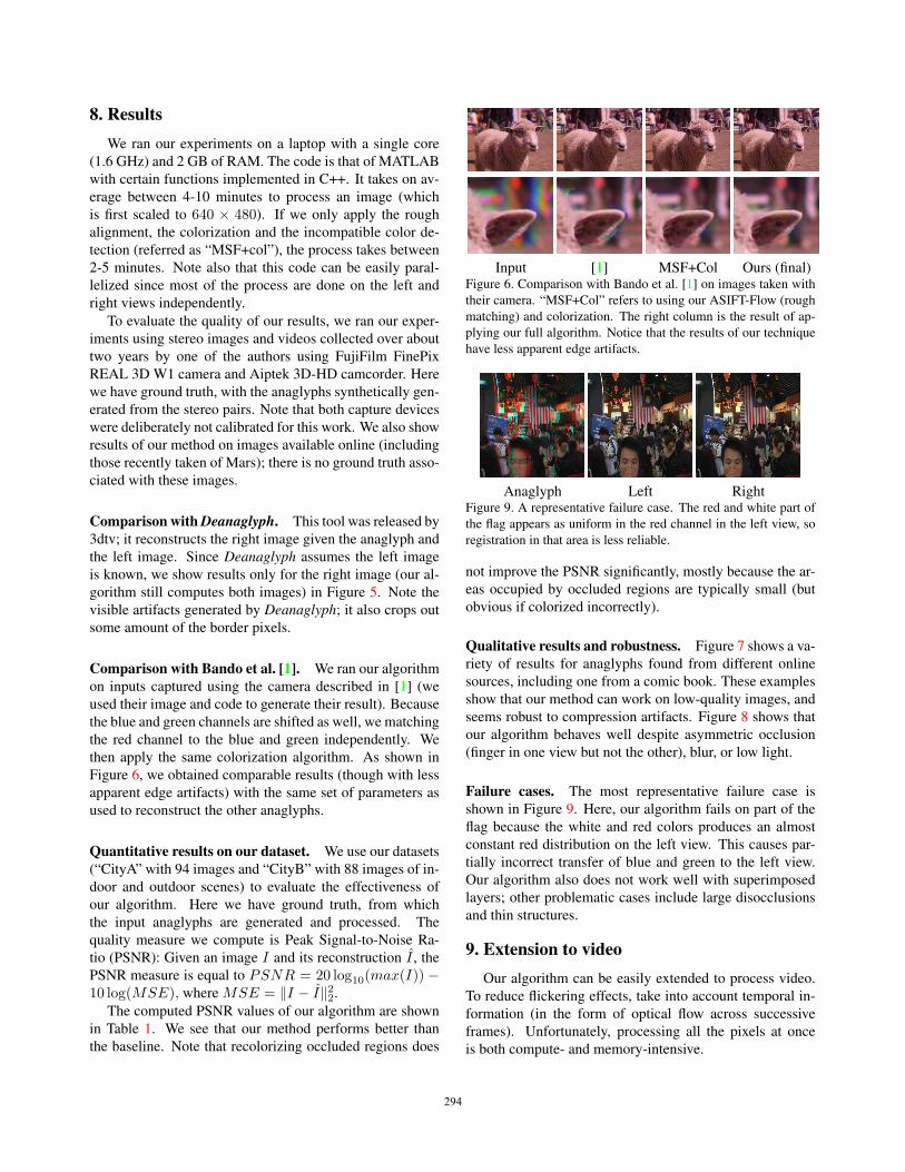
Deanaglyph Ours Ground truthFigure 5. Comparison with Deanaglyph (http://www.3dtv.at/Knowhow/DeAnaglyph_en.aspx).
Dataset # Images View SIFT-Flow ASIFT-Flow ASIFT-Flow + Col Ours - Occ Ours
CityA 94 left 20.8 21.7 28.2 28.5 28.6right 21.2 22.0 29.1 29.3 29.5
CityB 88 left 20.5 22.3 30.2 30.7 30.7right 19.9 21.6 30.9 31.3 31.4
Table 1. Quantitative results in PSNR. (a) SIFT-Flow, (b) ASIFT-Flow (coarse matching), (c) ASIFT-Flow (coarse matching) and coloriza-
tion, (d) Ours without handling incompatible colors, (e) Ours. The best number on each row is shown in bold. Examples from this dataset
can be found in the supplementary file.
For efficiency reasons, we perform rough channel align-
ment each frame independently. We impose additional cri-
teria on good correspondences, that of temporal match reci-procity: two pixels connected by the optical flow between
two consecutive frames of the left view are matched to pix-
els of the right view that are also connected by the optical
flow. Let ORt�→t+1 be the optical flow from the frame t to
t+1 on the right view. The additional criteria for a pixel i of
the t-th frame of the left view are ORt �→t+1(ML �→R(i)) ==
ML �→R(OLt �→t+1(i)) as well as the right view counterpart.
Our colorization algorithm is extended to videos by com-
puting similarity matrices within a frame Wt and between
consecutive frames, Wt,t+1. The similarity matrix within a
frame is similar to the one used it the case of images. Given
a pixel i and its optical flow Ot �→t+1(i), the entries W ijt,t+1
of similarity matrix between consecutive frames are zero if
in frame t+1, the two pixels Ot �→t+1(i) and j are not within
10 pixels of each other. Otherwise W ijt,t+1 is equal to:
exp(−γ‖It(i)− It+1(j)‖22)δ(‖It(i)− It+1(j)‖1 ≤ λI).
We define our similarity matrix W over the whole sequence
as the block matrix with Wt on the diagonal and Wt,t+1
on the second diagonal. We define the Laplacian matrix
L = I −D−1W as before. We use a temporal window ap-
proach where each frame is colorized given its consecutive
frames. This block coordinate descent scheme converges
to the global minimum since the cost function is strongly
convex and is linear in the number of pixels to colorize.
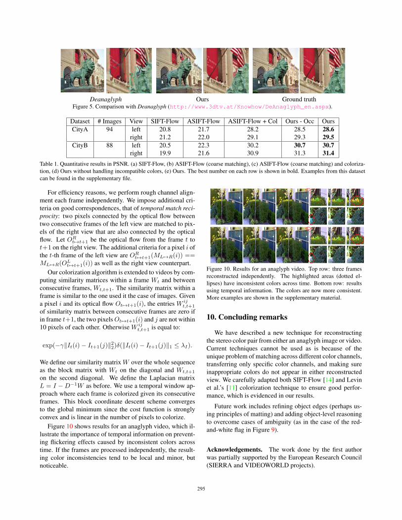
Figure 10 shows results for an anaglyph video, which il-
lustrate the importance of temporal information on prevent-
ing flickering effects caused by inconsistent colors across
time. If the frames are processed independently, the result-
ing color inconsistencies tend to be local and minor, but
noticeable.
Figure 10. Results for an anaglyph video. Top row: three frames
reconstructed independently. The highlighted areas (dotted el-
lipses) have inconsistent colors across time. Bottom row: results
using temporal information. The colors are now more consistent.
More examples are shown in the supplementary material.
10. Concluding remarks
We have described a new technique for reconstructing
the stereo color pair from either an anaglyph image or video.
Current techniques cannot be used as is because of the
unique problem of matching across different color channels,
transferring only specific color channels, and making sure
inappropriate colors do not appear in either reconstructed
view. We carefully adapted both SIFT-Flow [14] and Levin
et al.’s [11] colorization technique to ensure good perfor-
mance, which is evidenced in our results.
Future work includes refining object edges (perhaps us-
ing principles of matting) and adding object-level reasoning
to overcome cases of ambiguity (as in the case of the red-
and-white flag in Figure 9).
Acknowledgements. The work done by the first author
was partially supported by the European Research Council
(SIERRA and VIDEOWORLD projects).
295295295
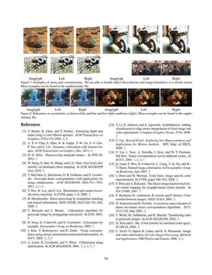
Anaglyph Left Right Anaglyph Left RightFigure 7. Examples of stereo pair reconstruction. We are able to handle object disocclusions and image boundaries to a certain extent.
More examples can be found in the supplementary file.
Anaglyph Left Right Anaglyph Left RightFigure 8. Robustness to asymmetric occlusion (left) and blur and low-light conditions (right). More examples can be found in the supple-
mentary file.
References[1] Y. Bando, B. Chen, and T. Nishita. Extracting depth and
matte using a color-filtered aperture. ACM Transactions onGraphics, 27(5):134, 2008. 2, 6
[2] A. Y.-S. Chia, S. Zhuo, R. K. Gupta, Y.-W. Tai, S.-Y. Cho,
P. Tan, and S. Lin. Semantic colorization with internet im-
ages. ACM Transactions on Graphics, Dec. 2011. 4
[3] H. G. Dietz. Reprocessing anaglyph images. In SPIE EI,2012. 1
[4] W. Dong, G. Bao, X. Zhang, and J.-C. Paul. Fast local color
transfer via dominant colors mapping. In ACM SIGGRAPHAsia, 2010. 2
[5] Y. HaCohen, E. Shechtman, D. B. Goldman, and D. Lischin-
ski. Non-rigid dense correspondence with applications for
image enhancement. ACM SIGGRAPH, 30(4):70:1–70:9,
2011. 2, 3, 4
[6] Y. Heo, K. Lee, and S. Lee. Illumination and camera invari-
ant stereo matching. In CVPR, pages 1–8, 2008. 2
[7] H. Hirschmuller. Stereo processing by semiglobal matching
and mutual information. IEEE TPAMI, 30(2):328–341, Feb.
2008. 2
[8] T. Horiuchi and S. Hirano. Colorization algorithm for
grayscale image by propagating seed pixels. In ICIP, 2003.
4
[9] R. Irony, D. Cohen-Or, and D. Lischinski. Colorization by
example. Eurographics Symp. on Rendering, 2005. 2
[10] J. Kim, V. Kolmogorov, and R. Zabih. Visual correspon-
dence using energy minimization and mutual information. In
ICCV, 2003. 2, 3, 4
[11] A. Levin, D. Lischinski, and Y. Weiss. Colorization using
optimization. In ACM SIGGRAPH, 2004. 1, 2, 4, 5, 7
[12] Y. Li, E. Adelson, and A. Agarwala. Scribbleboost: Adding
classification to edge-aware interpolation of local image and
video adjustments. Computer Graphics Forum, 27(4), 2008.
2
[13] C. Liu. Beyond Pixels: Exploring New Representations andApplications for Motion Analysis. MIT, Dept. of EECS,
2009. 2
[14] C. Liu, J. Yuen, A. Torralba, J. Sivic, and W. T. Freeman.
Sift flow: Dense correspondence across different scenes. In
ECCV, 2008. 1, 2, 3, 7
[15] Q. Luan, F. Wen, D. Cohen-Or, L. Liang, Y.-Q. Xu, and H.-
Y. Shum. Natural image colorization. In Eurographics Symp.on Rendering, June 2007. 2
[16] I. Omer and M. Werman. Color lines: image specific color
representation. In CVPR, pages 946–953, 2004. 2
[17] F. Pitie and A. Kokaram. The linear monge-kantorovitch lin-
ear colour mapping for example-based colour transfer. In
IET CVMP, 2007. 2
[18] E. Reinhard, M. Ashikhmin, B. Gooch, and P. Shirley. Color
transfer between images. IEEE CG&A, 2001. 2
[19] D. Scharstein and R. Szeliski. A taxonomy and evaluation of
dense two-frame stereo correspondence algorithms. IJCV,
47(1):742, May 2002. 2
[20] T. Welsh, M. Ashikhmin, and K. Mueller. Transferring color
to greyscale images. In ACM SIGGRAPH, 2002. 2
[21] X. Xiao and L. Ma. Color transfer in correlated color space.
In VRCIA, 2006. 2
[22] L. Yatziv, G. Sapiro, R. Lukac, and K. N. Plataniotis. Image
and video colorization. In Color Image Processing: Methodsand Applications. CRC/Taylor and Francis, 2006. 2, 4
296296296