Embed Size (px)
Citation preview
RECONSTRUCTION OF GROUND PENETRATING RADAR BACKSCATTER OF
SUBSURFACE FEATURES FOR UTILITY MAPPING
JAW SIOW WEI
A thesis submitted in fulfilment of the
requirements for the award of the degree of
Doctor of Philosophy (Remote Sensing)
Faculty of Geoinformation and Real Estate
Universiti Teknologi Malaysia
JULY 2013
iii
This work is dedicated with love and passion to
my father, Jaw Ah Fat
my mother, Chan Wai Fong
my brothers, Siong Meng & Siong Kin
my sisters-in-law, Stacey & Kah Teng
my nieces, Jane & Winnie
my boy-friend, Tiong Chiong Ung
my best friend, Lim Meng Chan
and not forgotten
my friends, Chin Yow Cheong, Tam Tze Huey, Foo Yen Sin,
Tan Kian Pang, Yap Xen Quen, Norsheilla Binti Mohd Johan & Nurul Nadiah
Binti Yahya
Thank you very much for all your encouragements, support and help
iv
ACKNOWLEDGEMENTS
First and foremost, I am deeply indebted to my supervisors, Prof. Sr. Dr. Mazlan
Hashim for his guidance, encouragements, and support during this research. Special
thanks are also given to Assoc. Prof. Dr Maged Marghany, and Dr. Mohamed Saad
Mostafa El-Mahallawy for their contribution in enhancing the quality of this research.
To Department of Survey and Mapping Malaysia (JUPEM), RDG Supply Sdn. Bhd. and
Ministry of Science, Technology and Innovation, Malaysia (MOSTI) for their valuable
technical and financial assistance given in this research. Special thanks go also to UTM
and INSTeG for giving me a good research environment. Without them, this research
could not have been completed.
Without all these organizations support, this thesis could not be completed on
time. They deserve my thanks for all the help they have given me until the completion
of this thesis and achieved awards in national and international level and produced high
impact publications. Among all the awards that achieved were (i) JSPRS Award by
Japan Society of Photogrammetry and Remote Sensing; (ii) Silver Award in Malaysia
Technology Expo (MTE 2013); (iii) Silver Award in Industrial Art and Technology
Exhibition (INATEX 2012); and (iv) Third Prize in Technical Paper Writing
Competition in National Geomatics/Geoinformatic Students Innovation Competition
2012. Last but not least, part of the work of this study was published in high impact (IF:
1.106) journal, namely Journal of Tunnelling and Underground Space Technology as
well as in Scopus Indexed Conferences such as IEEE.
v
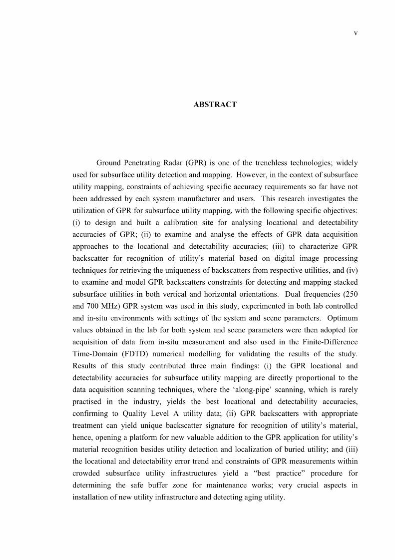
ABSTRACT
Ground Penetrating Radar (GPR) is one of the trenchless technologies; widely
used for subsurface utility detection and mapping. However, in the context of subsurface
utility mapping, constraints of achieving specific accuracy requirements so far have not
been addressed by each system manufacturer and users. This research investigates the
utilization of GPR for subsurface utility mapping, with the following specific objectives:
(i) to design and built a calibration site for analysing locational and detectability
accuracies of GPR; (ii) to examine and analyse the effects of GPR data acquisition
approaches to the locational and detectability accuracies; (iii) to characterize GPR
backscatter for recognition of utility’s material based on digital image processing
techniques for retrieving the uniqueness of backscatters from respective utilities, and (iv)
to examine and model GPR backscatters constraints for detecting and mapping stacked
subsurface utilities in both vertical and horizontal orientations. Dual frequencies (250
and 700 MHz) GPR system was used in this study, experimented in both lab controlled
and in-situ environments with settings of the system and scene parameters. Optimum
values obtained in the lab for both system and scene parameters were then adopted for
acquisition of data from in-situ measurement and also used in the Finite-Difference
Time-Domain (FDTD) numerical modelling for validating the results of the study.
Results of this study contributed three main findings: (i) the GPR locational and
detectability accuracies for subsurface utility mapping are directly proportional to the
data acquisition scanning techniques, where the ‘along-pipe’ scanning, which is rarely
practised in the industry, yields the best locational and detectability accuracies,
confirming to Quality Level A utility data; (ii) GPR backscatters with appropriate
treatment can yield unique backscatter signature for recognition of utility’s material,
hence, opening a platform for new valuable addition to the GPR application for utility’s
material recognition besides utility detection and localization of buried utility; and (iii)
the locational and detectability error trend and constraints of GPR measurements within
crowded subsurface utility infrastructures yield a “best practice” procedure for
determining the safe buffer zone for maintenance works; very crucial aspects in
installation of new utility infrastructure and detecting aging utility.
vi
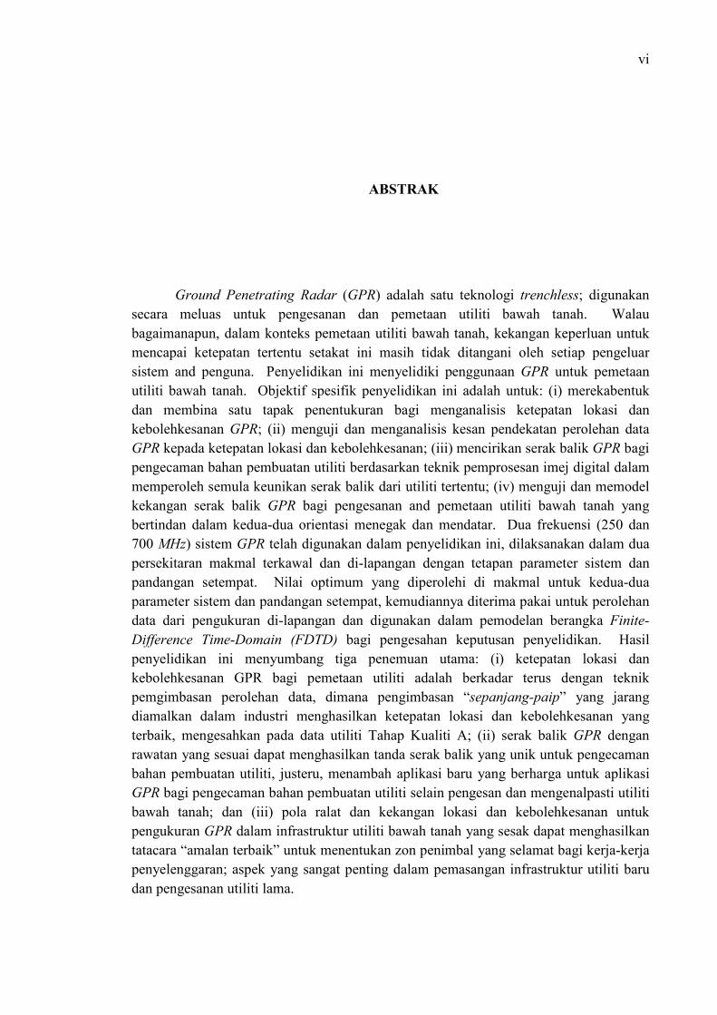
ABSTRAK
Ground Penetrating Radar (GPR) adalah satu teknologi trenchless; digunakan
secara meluas untuk pengesanan dan pemetaan utiliti bawah tanah. Walau
bagaimanapun, dalam konteks pemetaan utiliti bawah tanah, kekangan keperluan untuk
mencapai ketepatan tertentu setakat ini masih tidak ditangani oleh setiap pengeluar
sistem and penguna. Penyelidikan ini menyelidiki penggunaan GPR untuk pemetaan
utiliti bawah tanah. Objektif spesifik penyelidikan ini adalah untuk: (i) merekabentuk
dan membina satu tapak penentukuran bagi menganalisis ketepatan lokasi dan
kebolehkesanan GPR; (ii) menguji dan menganalisis kesan pendekatan perolehan data
GPR kepada ketepatan lokasi dan kebolehkesanan; (iii) mencirikan serak balik GPR bagi
pengecaman bahan pembuatan utiliti berdasarkan teknik pemprosesan imej digital dalam
memperoleh semula keunikan serak balik dari utiliti tertentu; (iv) menguji dan memodel
kekangan serak balik GPR bagi pengesanan and pemetaan utiliti bawah tanah yang
bertindan dalam kedua-dua orientasi menegak dan mendatar. Dua frekuensi (250 dan
700 MHz) sistem GPR telah digunakan dalam penyelidikan ini, dilaksanakan dalam dua
persekitaran makmal terkawal dan di-lapangan dengan tetapan parameter sistem dan
pandangan setempat. Nilai optimum yang diperolehi di makmal untuk kedua-dua
parameter sistem dan pandangan setempat, kemudiannya diterima pakai untuk perolehan
data dari pengukuran di-lapangan dan digunakan dalam pemodelan berangka Finite-Difference Time-Domain (FDTD) bagi pengesahan keputusan penyelidikan. Hasil
penyelidikan ini menyumbang tiga penemuan utama: (i) ketepatan lokasi dan
kebolehkesanan GPR bagi pemetaan utiliti adalah berkadar terus dengan teknik
pemgimbasan perolehan data, dimana pengimbasan “sepanjang-paip” yang jarang
diamalkan dalam industri menghasilkan ketepatan lokasi dan kebolehkesanan yang
terbaik, mengesahkan pada data utiliti Tahap Kualiti A; (ii) serak balik GPR dengan
rawatan yang sesuai dapat menghasilkan tanda serak balik yang unik untuk pengecaman
bahan pembuatan utiliti, justeru, menambah aplikasi baru yang berharga untuk aplikasi
GPR bagi pengecaman bahan pembuatan utiliti selain pengesan dan mengenalpasti utiliti
bawah tanah; dan (iii) pola ralat dan kekangan lokasi dan kebolehkesanan untuk
pengukuran GPR dalam infrastruktur utiliti bawah tanah yang sesak dapat menghasilkan
tatacara “amalan terbaik” untuk menentukan zon penimbal yang selamat bagi kerja-kerja
penyelenggaran; aspek yang sangat penting dalam pemasangan infrastruktur utiliti baru
dan pengesanan utiliti lama.
vii
TABLE OF CONTENTS
CHAPTER TITLE PAGE
DECLARATION ii
DEDICATION iii
ACKNOWLEDGMENTS iv
ABSTRACT v
ABSTRAK vi
TABLE OF CONTENTS vii
LIST OF TABLES xi
LIST OF FIGURES xii
LIST OF SYMBOLS xvi
LIST OF ABBREVIATIONS xviii
LIST OF APPENDICES xx
1 INTRODUCTION 1
1.1 Background of the Study 1
1.2 Problem Statement 6
1.3 Objectives of the Study 10
1.4 Scopes of the Study 11
1.5 Significance of the Study 13
1.6 Research Design 17
1.7 Organization of the Thesis 20
viii
2 DESIGN AND BUILT CALIBRATION TEST SITE
FOR ANALYSING LOCATIONAL AND
DETECTABILITY OF GPR ACCURACIES
22
2.1 Introduction 22
2.2 National Testing Facility 23
2.3 Design Methodology 27
2.3.1 Construction Work for Building the Test Site 27
2.3.2 Marking Buried Utility 32
2.3.3 Levelling and Global Positioning System (GPS)
Survey
34
2.4 Results 36
2.4.1 Layout and Design of the Test Site 36
2.5 Discussions 38
2.5.1 Advantages of the Design 38
2.6 Concluding Remarks 42
3 GPR DATA ACQUISITION APPROACHES AND
EFFECTS TO LOCATIONAL ACCURACY AND
DETECTABILITY OF SUBSURFACE UTILITY
FEATURES
47
3.1 Introduction 47
3.2 State-of-the-Art of Subsurface Utility Mapping 50
3.2.1 Subsurface Utility Features 50
3.2.2 Utility Mapping Sensing Technologies 52
3.2.3 One-Call Centre 55
3.2.4 Mapping the Underworld (MTU) 60
3.2.5 Utility Mapping Guideline / Standard Operating
Procedures (SOP)
62
3.2.6 Utility Mapping and Its Challenge 68
3.3 Materials and Methods 72
3.3.1 GPR System Description 72
3.3.2 Test Site Description 74
3.3.3 Data Processing 76
ix
3.4 Results 82
3.5 Discussions 87
3.5.1. Case Study at Persiaran Kewajipan, Subang Jaya 89
3.6 Concluding Remarks 90
4 CHARACTERIZATION OF GPR BACKSCATTER
FOR RECOGNITION OF UTILITY’S FABRICATION
MATERIAL
91
4.1 Introduction 91
4.2 Ground Penetrating Radar (GPR)- A popular Trenchless
Technology for Subsurface Utility Mapping
95
4.2.1 Background Theory of GPR System 96
4.2.2 GPR Antenna 96
4.2.3 GPR Scanning Mechanism 99
4.2.4 GPR Data Analysis 102
4.3 Materials and Methods 111
4.3.1 Description of the Test Site 111
4.3.2 Data Acquisition 112
4.3.3 Data Processing 118
4.3.4 Numerical Modelling 119
4.3.5 Feature Detection 122
4.4 Results 125
4.4.1. Soil Moisture Laboratory Experiment- Oven-dry
Method
125
4.4.2 Feature Extraction 126
4.5 Discussions 134
4.6 Concluding Remarks 145
5 CONSTRAINTS OF GPR BACKSCATTER FOR
DETECTING AND MAPPING VERTICALLY AND
HORIZONTALLY STACKED SUBSURFACE
UTILITIES FEATURES
146
5.1 Introduction 146
x
5.2 Locating Technologies for Utility Mapping 150
5.2.1 Trenchless Technologies for Utility Mapping 150
5.2.2 Principle of GPR 154
5.2.3 GPR Image Formation 158
5.3 Materials and Methods 160
5.3.1 Experimental Test Site Description 160
5.3.2 Data Acquisition 161
5.3.3 Pre-processing 163
5.3.4 Numerical Modelling 163
5.3.5 Feature Detection 165
5.4 Results 166
5.4.1 Signal Wavelength Computation 166
5.4.2 Feature Detection 167
5.4.3 Statistical Assessment 170
5.5 Discussions 171
5.6 Concluding Remarks 173
6 CONCLUSIONS AND RECOMMENDATIONS 174
6.1 Conclusions 174
6.2 Recommendations 178
6.2.1 Establish a Multipurpose National Testing Facility 178
6.2.2 Establish Standard Operating Procedures for
Utility Mapping
179
6.2.3 Professional Training for Certification 180
6.2.4 Regularly Updates the Utility Map 180
6.2.5 Additional Research 182
REFERENCES 183
Appendices A-D 200 - 213
xi
LIST OF TABLES
TABLE NO. TITLE PAGE
2.1 Localized Colour Code for Utility Marking 33
2.2 Universal Colour Code for Utility Marking 33
2.3 Location Details of the Buried Utilities 37
2.4 Summary of the Design Details of the Test Site 45
3.1 The Classification of Various Subsurface Utility Features by
Its Fabrication Components and Functions
51
3.2 Comparison of Different Frequency GPR System with Its Depth
of Penetration and Applications
54
3.3 List of Utility Companies Operating In Malaysia 69
3.4 IDS Detector Duo Technical Specifications 73
3.5 Summary of Performance for Each GPR Data Acquisition
Scanning Technique
83
4.1 The Information of the Buried Utility Features in These Test
Sites
112
4.2 Metallic and Non-Metallic Utility Feature’s Fabrication
Material
114
4.3 Different Types of Backfill Materials (Or Construction
Sand)
116
4.4 Summary of Descriptive Statistics for Practical Data 124
4.5 Results of the Moisture Content of the Soil Samples 125
5.1 Summary of the Typical Velocities and Attenuation of the
Common Materials
155
xii
LIST OF FIGURES
FIGURE NO. TITLE PAGE
1.1 Key Element To Damage Prevention 5
1.2 Research Plan Flowchart 19
2.1 Some of the Test Sites Available on the Market 26
2.2 Location of the Test Site 27
2.3 Design of the Test Site (a) 3-D View and (b) Side View 28
2.4 Material for Test Site Construction 29
2.5 Compartment Structure of the Test Site with Its Host
Material
31
2.6 Marking Using Utility Colour Code Provided By JUPEM 32
2.7 Levelling Survey for Determining Depth Alignment 34
2.8 GPS Survey 35
2.9 The layout of the Test Site Located at FGRE, UTM Johor
Bahru
36
2.10 The Proposed Calibration Certificate 41
3.1 Unnecessary By-Pass Cables that Tarnished and
Jeopardized the City Image
56
3.2 Work Flows for the One-Call Centre 59
3.3 Utility Data Attributes Quality Level 66
3.4 National Underground Utility Database 69
3.5 Data Flow of Utility Mapping 70
3.6 Issues and challenges In Malaysia 71
3.7 The Appearance of IDS Detector Duo GPR System 72
3.8 The Details of the Utility Features (a) Test Site 1(located
at Wisma JUPEM, KL) and (b) Test site 2 (located at
75
xiii
FGRE, UTM Johor Bahru)
3.9 Scanning Orientation for Each Scanning Technique 81
3.10 Target Detectability Results for Test Site 1 84
3.11 Target Detectability Results for Test Site 2 85
3.12 Result of Numerical Modelling Analysis Using GprMax
Simulator
88
3.13 Target Detectability Result for the Case Study 90
4.1 Different Antenna Configuration of GPR System 97
4.2 Antenna Type (a) Shielded Antenna and (b) Unshielded
Antenna
98
4.3 Formation of the Hyperbola in Radargram 101
4.4 Data Processing Flow of 2D GPR Data 104
4.5 Yee Cell Used For FDTD 109
4.6 Experiment for Soil Moisture Measurement Using the
Over-Dry Method (a) Soil Samples for Experiment; (b)
Soil Moisture Measurement Experiment; (c) Soil Samples
Collected from the Test Site; (d) Weighting Different
Types of Soil Samples; (e) Prepare Samples for Oven-Dry;
and (f) Measure the Mass of Soil Samples
117
4.7 Matrix Sample for Simulation 120
4.8 Structure of Test Site 1 120
4.9 Flowchart of FDTD Modelling Procedures 121
4.10 Methodology Flowchart for Material Recognition (a) Data
Acquisition; (b) Pre-Processing; (c) Feature Detection; and
(d) Retrieval of Absolute Backscatter Signature
123
4.11 The Thresholding Segmentation Coding 124
4.12 Simulation Image Containing Combination of Nine
Different Utility Features Buried Near To Each Other’s
127
4.13 Different Fabrication Material Containing Different
Hyperbola Pattern (a) Ductile Iron; (b) Mild Steel; (c)
Clay; (d) PVC; (e) HDPE; and (f) MDPE
129
4.14 Variation Buried Depth’s Simulation Images for Mild
Steel (a) 2.515 m; (b) 2.315 m; (c) 2.115 m; (d) 1.915 m;
130
xiv
(e) 1.715 m; and (f) 1.515 m
4.15 Different Surrounding Host Material’s Simulation Images
for Mild Steel (a) Dry Fine Sane; (b) Wet Fine Sand; (c)
Dry Coarse Sand; (d) Silty; (e) Dry Gravel; and (f) Wet
Gravel)
131
4.16 Results of Feature Detection (a) Test Site 1; (b) Test Site
2; and (c) Thean Hou Temple, near Robson Heights,
Malaysia.
132
4.17 Absolute Backscatter Signature Extracted from Simulation
Images Generated Based on Different Utility’s Fabrication
Material
135
4.18 Absolute Backscatter Signature Extracted from Simulation
Images Generated Based on Different Buried Depth
136
4.19 Absolute Backscatter Signature Extracted from Simulation
Images Generated Based on Using Fine Sand as
Surrounding Host Material
137
4.20 Absolute Backscatter Signature Extracted from Simulation
Images Generated Based on Using Coarse Sand as
Surrounding Host Material
138
4.21 Absolute Backscatter Signature Extracted from Simulation
Images Generated Based on Using Gravel as Surrounding
Host Material
139
4.22 Absolute Backscatter Signature Extracted From Case
Study Experimented at Test Site 1
142
4.23 Absolute Backscatter Signature Extracted From Case
Study Experimented at Test Site 2
143
4.24 Absolute Backscatter Signature Extracted from Case Study
Experimented Under Real World Condition at Thean Hou
Temple, Malaysia
144
5.1 Horizontal and Vertical Coverage Detail 149
5.2 Available Locating Technologies for Subsurface Utility
Mapping
151
5.3 Commonly Used Technologies for Utility Mapping 151
xv
5.4 GPR System That Commercially Available in Today’s
Market
153
5.5 Principle of GPR System 156
5.6 GPR Imaging Mechanism 157
5.7 Photo of the Test Site (Side View) 161
5.8 Pre-Processing Routine 163
5.9 Input Matrix for Simulation of (a) Vertically Stacked and
(b) Horizontally Stacked Subsurface Utility Features
164
5.10 Utility Congestion Situation within Current Subsurface
Spaces (a) Congested Shallow Subsurface Cause Trouble
for Determination of Type of Pipe; (b) Lack of Space for
Burying Pipes; (c) Stacking of Gas Line in a 150mm
Sewer Line by HDD; and (d) Vertically and Horizontally
Stacked Utility Features
165
5.11 Horizontally Stacked Buried Utility Features With
Different Interval Distances for Examining the Sensing
Constraints of GPR System
168
5.12 Vertically Stacked Buried Utility Features With Different
Interval Distances for Examining the Sensing Constraints
of GPR System
169
5.13 RMSE versus the Interval Distance between Two Adjacent
Utilities that Horizontally Stacked
170
5.14 RMSE versus the Interval Distance between Two Adjacent
Utilities that Vertically Stacked
171
xvi
LIST OF SYMBOLS
D - Depth of the target
v - Electromagnetic wave travel velocity
t - Two-way travel time (TWT) of electromagnetic wave
X’, Y’ - Coordinates for points at subsurface
x, y - Coordinates for points at the ground surface
Xm, Ym - Mean of transformed points
xm, ym - Mean of the observed points
N - Number of points observed
rxi, ryi - Residual of a sample point
Zo - Observed depth
Z - Computed depth
∆t - Time delay
εr - Dielectric relative permittivity
cm - Speed of light
tn - Echo delay in position yn
t0 - Echo delay
i0, j0 - Hyperbola apex
Γ2 - Voltage reflectance coefficient at a lower surface
σt - Material’s cross-section
d - Distance travel by signal
τ - Layer thickness
µ - Magnetic permeability
σ - Electrical conductivity / standard deviation
T - Threshold values
n - nth of utility

xvii
λ - wavelength
ô - Object distribution
R1 (t) - Backscatter amplitudes
Tn - Distance from the antenna to point (x1, y1, z1)
xt, yt, zt - Location of transmitter
, , - Location of the receiver
nrx nry nrz
xviii
LIST OF ABBREVIATIONS
ABS - Acrylonitrile-butadiene-stryrene
ANOVA - Analysis of variance
APWA - American Public Works Association
ASCE - American Society of Civil Engineering
BGS - British Geological Society
CAT - Cable Avoidance Tool
CCTV - Closed-circuit television
CEM - Computation electromagnetic methods
COTS - Commercial Off-The-Shelf
DC - Direct Current
DE - Differential Equation
DI - Ductile Iron
EM - Electromagnetic
EPSRC - Engineering and Physical Sciences Research Council
FDTD - Finite-Difference Time-Domain
FGRE - Faculty of Geoinformation and Real Estate
FMCW - Frequency Modulated Continuous Waveform
FRP - Fiberglass Reinforced Plastic
GIS - Geographical Information System
GPR - Ground Probing Radar/ Ground Penetrating Radar
GPS - Global Positioning System
HDD - Horizontal Directional Drilling
HDPE - High Density Polyethylene
IDS - Ingegneria Dei Sistemi
IE - Integral Equation
xix
JUPEM - Jabatan Ukur dan Pemetaan Malaysia
KDI - Knowledge and Data Integration
MDPE - Medium Density Polyethylene
MOSTI - Ministry of Science, Technology and Innovation
MS - Mild Steel
MTU - Mapping the Underworld
NETTWORK - Engineering Programme Network in Trenchless
Technologies
PADU - Pangkalan Data Pemetaan Utiliti Kebangsaan
PE - Polyethylene
PML - Perfectly Match Layer
PVC - Polyvinyl chloride
R&D - Research and Development
RMSE - Root mean square error
RTK - Real-time Kinematik
SAR - Synthetic-Aperture Radar
SFCW - Stepped Frequency Continuous Waveform
SNR - Signal-to-Noise Ratio
SOP - Standard Operation Procedure
SUE - Subsurface Utility Engineering
SYABAS - Syarikat Bekalan Air Selangor
TWT - Two-way travel time
UHF - Ultra High Frequency
UKWIR - UK Water Industry Research
UTHM - Universiti Tun Hussein Onn Malaysia
UTM - Universiti Teknologi Malaysia
VHF - Very High Frequency
WADGPS - Wide Area Differential GPS
xx
LIST OF APPENDICES
APPENDIX TITLE PAGE
A Simulation Images for Different Buried Depth 200
B The Specification of GPR Systems, Available
on the Market
205
C List of Publications 208
D List of Awards 210
1
CHAPTER 1
INTRODUCTION
1.1 Background of the Study
Utility infrastructure such as electricity, water, gas, sanitary sewers and
telecommunication has played a significant role in facilitating agriculture, industrial,
business activities and sustaining human's daily life since ancient civilization until
present. Rapid urbanization as well as fast paced urban population growth has caused
the expansion of these utility infrastructures. Since World War II, the utility
infrastructure in United States (U.S) has increased approximately 14 million miles
(GeoSpec LLC, 2002). Whereas the electricity, treated water, and communication
coverage in the rural areas of Peninsular Malaysia, Sabah and Sarawak is expected to
reach almost 100% and 99% respectively by year 2015 (Economic Planning Unit, 2010).
It is particularly essential to meet the demands of utility infrastructure in order to cater to
the economic activities and luxurious life of the cities. As such, this has resulted in
booming of construction work in the utility industry to replace or maintain the aging
utility infrastructure for expansion of utility services to the backward and underserved
areas.
In this context, utility owners adopt a measure to place their utility networks in
the subsurface for space saving and have better design of the urban landscape (Jorge et
al., 2010). Moreover, by burying the utility pipeline in the subsurface, it can reduce the
2
use of unnecessary by-pass cables which may tarnish and jeopardize the city landscape.
However, rapid development over the country has led to the limited use of surface land,
property on the land and underground spaces. Most of the densely populated countries
especially the Hong Kong, Taiwan, Singapore and Japan are experiencing issue of land
shortage. The spaces within the subsurface are extremely limited; yet the utility owners
still persistently placed their networks in the subsurface. The shallow subsurface in
urban, industrial and environmentally sensitive areas are now fully occupied by different
utility networks; forming a labyrinthine network of utility networks (refers Figure 5.10).
Under such utility congestion circumstance, it is exceedingly difficult and
troublesome to map these buried utilities as they are invisible to the naked eye.
Moreover, most of the utilities that have been buried since long ago, are generally not
archived. Even if, they are archived, the records are mostly in the form of two-
dimensional hardcopy map. In this sense, mapping of buried utility has become more
challenging task especially with deficiency of buried utility information. It often
contributes to the increment of utility damaging incidence and adverse impacts to the
contractors, utility owners and even the public. The impacts not only inconvenience the
urban dweller, in the form of interruptions in electricity, telephone, traffic system, water
and gas supplies, it may also causes explosions and mortalities when the workers
accidentally hit the utility pipelines, especially the gas pipe or electrical cable.
The numbers of utility damages are increasing rapidly in response with
increasing numbers of construction work for utility maintenance and rehabilitation. The
costs of these damages are often notable and on the rise. In each single year,
approximately USD 12.9 billion has been expended by Malaysia government for
construction work of utility maintenance caused by failed excavation. In US, total loss
of utility damages in year 1993 was exceeding USD 83 million and around USD 0.7
million in year 1997 (Costello et al., 2007; Doctor et al., 1995; Economic Planning Unit,
2006; Stinson, 1998). In UK, the spending for third party utility damages are USD 227.4
million while the social expenses per year for street work due to traffic relocation, air
pollution, business disruption, etc. is almost USD 77 billion (Costello et al., 2007;
Doctor et al., 1995). In fact, the cost of losses for utility damages is not little, because
3
the stakeholders often underreported the actual cost of losses due to utility damages.
According to Heinrich (1996) and Lorenc and Bernold (1998), the originally
construction cost for utility maintenance is expected to be twenty times more than the
original costs that reported in the media.
Subsurface Utility Engineering (SUE) - an engineering practise is developed to
address the problems of inaccurate utility mapping. It is the engineering survey that used
to determine the position or location of the natural or manmade structure on, above or
beneath the earth’s surface. According to American Society of Civil Engineers (2002),
SUE is the engineering practise that developed to manage the risks related to utility
mapping under appropriate quality level, utility relocation, precise utility coordination,
implementation of utility related policies and others responsibility related to utility
sectors. SUE, which comprises civil engineering practises, geophysical imaging
technologies, surveying and data management skills, are widely used for acquiring good
quality utility’s information in majority of the mapping projects (Jeong et al., 2003).
With precisely locating the buried utility and presenting it in the form a map, it can ease
the task of utility relocation and installation; avoid construction delays, incidents and
damages to the third party utility networks.
According to Metje et al., (2007), the Cable Avoidance Tool (CAT) is the
conventional utility detection tool. It contains a magnetic field sensor which operates in
either the power, radio or generator mode. Although CAT was commonly used in UK
for detecting the buried utility, it still has limitation in detecting the utility which laid
closely together, overlay or crossing among each other. In an attempt to overcome this
problem, development of technology has led to the innovation of new non-destructive
system namely Ground Penetration Radar or Ground Probing Radar (GPR). At present,
GPR is one of the useful instruments in trenchless technology for examining the man-
made structure in determining its location and depth. GPR is now the top sensing tool
among all the equipment that is commercially available in today’s market due to its
advantages in providing high resolution imagery, fast data acquisition and good
interpretation results (Enes et al., 2010; Jeng et al., 2011; Jorge et al., 2010; Lester and
Bernold, 2007; Millington et al., 2009; Ni et al., 2010; Roger et al., 2009). It is highly
4
recommended for use in subsurface investigations, specifically for application of military,
civil or environmental engineering, geology, geophysics or transportation studies in
detecting subsurface utility, building rebar or cavities, spatial distribution of biogenic gas
from peatland and also landmines (Bello and Kamarudin, 2012a; Ahmet and Mehmet,
2011; Annan, 2005; Francke, 2011; Neal, 2004).
The development of new technology such as broadband in modern civilized life
has lead to increasing of new construction and expansion of subsurface utility networks.
GPR is often used to determine the location of the buried utility infrastructure in a utility
mapping project. It is now an essential means to reduce the adverse impacts of utility
damages before any construction work starts (Jeong et al., 2003). Despite diligent efforts
to detect these buried utility infrastructures before the excavation, the occurrences of
utility damage during excavation work are still arising. The losses due to these
excavation accidents can reach astronomical numbers and have caused dangerous and
hazardous effects to the environment and public. In this sense, there is always
unprecedented demand for precise and high efficiency subsurface utility mapping within
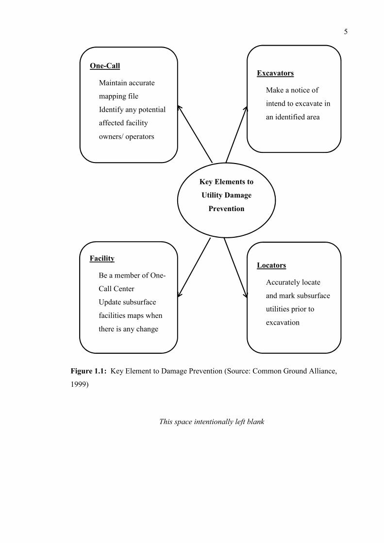
the utility industry. According to Common Ground’s study, determination of utility’s
location and retaining of accurate mapping information is essential for preventing utility
damages (refers Figure 1.1). Securing reliable information of the buried utility is, hence,
urgently required by current utility industry for preventing these excavation accidents to
recur. Therefore, mapping the attributes of subsurface utility features at the present time
is a significant task in the utility industries, particularly for the expansion and upgrading
the subsurface utility features (Balaogun et al., 2011; KPUP, 2006).
This space intentionally left blank
5
Figure 1.1: Key Element to Damage Prevention (Source: Common Ground Alliance,
1999)
Key Elements to
Utility Damage
Prevention
Excavators
Make a notice of
intend to excavate in
an identified area
Locators
Accurately locate
and mark subsurface
utilities prior to
excavation
One-Call
Maintain accurate
mapping file
Identify any potential
affected facility
owners/ operators
Facility
Be a member of One-
Call Center
Update subsurface
facilities maps when
there is any change
This space intentionally left blank
6
1.2 Problem Statement
GPR has been categorised as the best trenchless detection tool for subsurface
detection and mapping. However, the GPR signal is often affected by factors of the host
material’s physical properties, soil moisture, congestion of utility networks, clutter due to
non-targeted features and etc. By using an uncalibrated GPR system to acquire data for
the mapping subsurface features, it has led to problems of poor data quality and data
interpretation, due to the high uncertainties in imprecise subsurface utility mapping. In
this sense, this lead to the risk of “vulnerable” errors and created uncertainties for buried
utilities safety in most of the mapping projects. GPR systems, hence, require calibration
to minimise the risk of “vulnerable” errors before it can be used for subsurface utility
mapping. A practical calibration site is necessary to overcome the shortcomings of
current GPR systems. This is because real time GPR calibration is exceedingly costly
and currently there is a lack of absolute calibration sites to assess the performance of the
GPR equipment. All the calibration for the commercially available GPR system is done
relatively without any investigation; hence, the results are highly ambiguous for
subsurface utility mapping and give rise to high ambiguity in the mapping industry.
Despite the fact that GPR has been given considerable attention in subsurface
investigation application, current utility industries still less exposed to extensive
guidelines on proper procedures and accuracy requirement for subsurface utility mapping.
As such, it has created a gap between engineering practises and mapping disciplines for
understanding the GPR capabilities in subsurface utility mapping. For this reason,
“rather hit and miss” principle are practised widely by the street worker throughout the
utility mapping projects. With regard to this, “rather hit and miss” affair, it has
contributed to increment of failed excavation cases due to insufficient acquainted with
their duty of engineering survey (Costello et al., 2007; Lester and Bernold, 2007; Metje
et al., 2007). For every single year, many “dry hole” - the hole that digs during
excavation but failed to detect any utility has been left behind as a result of failed
excavation caused by imprecise subsurface utility mapping. Thereby, proper mapping
approach is essential for performing accurate subsurface utility mapping in order to
7
prevent “blind” excavation and undesirable consequences during construction works of
utility maintenance and rehabilitation.
Moreover, the stakeholders, like decision makers, utility owner, contractors,
surveyors, and even excavators, often overlook the need to perform precise subsurface
utility mapping because they assume that the utilities are usually buried in the subsurface
and invisible to the naked eye. The stakeholders even tend to underestimate the
destructive power caused by utility damages due to failed excavation, hence, they often
believe there is no need for accurately detect the position of the buried utilities (Koo and
Ariaratnam, 2006). The stakeholders did not giving priority attentions to the detection
accuracy and the potential errors of mapping. Additionally, to-date, there are not much
published literature regarding GPR data acquisition approach effect on locational and
detectability accuracies has been covering comprehensively. With regard to this, a
thorough investigation is required to be conducted for examining and analysing the
effects of data acquisition techniques on locational and detectability accuracies, is
needed urgently by current utility industry. This is to solve the issue of failed excavation
due to imprecise subsurface utility mapping which has been continuing to occur and
exacerbated.
Although GPR is established entirely for geophysical application in
understanding the location and depth of the buried utilities within local coordinate
system, it is somehow “underutilize” for understanding utility’s radiometric properties
such as utility’s fabrication material, radius or diameter and utility’s condition. At
present, only limited utility’s geometric properties, such as planimetric location and
depth, are being taken seriously by the stakeholders. The industry actually
misconception that GPR is only beneficial for extracting the geometric information of
the buried utilities. However, the reality is that backscatters from the object which
acquired by the GPR has enormous potential to be used to report the physical properties
of the object. The “feature information” of the object such as its shape, size and
condition, can be extracted from its backscatters. In this sense, the issues of (i) object
material recognition; (ii) object dimension estimation; and (iii) object size estimation are
still remaining open for research because plenty of research that currently conducted are
8
focused on object detection and localization issue only. However, complete details of
the buried utilities in term of its geometric and radiometric properties is actually essential
for the industry to perform civil engineering and surveying work, particularly excavation
for utility installation and repair. With these complete details, it will ensure safe
excavation with minimal traffic flow and business disruption.
The prerequisite for extracting buried utility’s geometry and radiometry physical
properties is through accurate interpretation of backscatter image, so call radargram.
Nowadays, GPR data processing and interpretation work are performed totally by
commercial software that is associated with the GPR system. This commercial software
belongs to the Commercial Off-The-Shelf (COTS) product, where end-users are unable
to configure any processing flow of the software for the necessity of their works. In this
context, most of the existing GPR software is aimed for commercial use and not for
research (Vera et al., 2008). The theory and source code that are used in the software is
not disclosed to the end-users, due to trade secret, thereby, the processing and
interpretation work can only be done in “black-box” manner. For every individual
processing and interpretation work done in the majority of the mapping projects, there is
no statistical assessment. This is because the results are depending mainly on the
operator’s interpretation experience and prior knowledge regarding the structure of the
subsurface features. The purpose of good interpretation for retrieving information from
the radargram which enables characterisation of subsurface physical or natural properties
rather than just to “see something” in the radargram are never being practised in the
industry. Numerical modelling analysis which able to simulate subsurface properties and
realistically represent the geometry and structure for subsurface feature and GPR antenna
under varying complex environment is, therefore, ideal for extraction of subtle
interpretation information from the radargram.
Utility services are the foundation of modern living for supporting the industrial,
agriculture and affluence life of the city. In relation to population growth and increased
of telecommunication technology such as the broadband services, it has causes many
new construction, reconstruction and development of new subsurface infrastructure to be
conducted around the world (Lester and Bernold, 2007). The utility owners attempt to
9
accommodate their networks randomly stacked (both vertically and horizontally) in the
first three meters of the subsurface, due to the deregulation of utility service. As such,
the shallow subsurface are now congested with different types of utility networks such as
oil and gas, electricity, sewer, water, cable TV, traffic signals, sanitary sewer, street
lighting circuit and even fibre optics. Under such congestion situation, the works of
utility maintenance and rehabilitation become difficult and often give rise to damage the
third party utilities. During the excavation, the machinery such as Horizontal Directional
Drilling (HDD), backhoe excavators, and plows are often could not “see” the third party
utilities when they are getting too close with it, unless remarkably precise location of the
utilities is provided by the utility owners. Herein, a uniform practice for alteration of an
existing installation, relocation of utilities or new utility installation within the shallow
subsurface is needed particularly to minimise the adverse effects on third party utility
safety, operations and maintenance. Therefore, all the problems mentioned above were
apparently resulted in the needs of conducting this research.
This space intentionally left blank
10
1.3 Objectives of the Study
The main aim of this study is to reconstruct ground penetrating radar backscatters
for subsurface utility features utilizing three digital image processing techniques namely;
image analysis, attribute analysis and modelling. The specific objectives of this study
are:
i) To design and built a calibration site for analysing locational and detectability
accuracies of GPR;
ii) To examine and analyse GPR data acquisition approaches effect on locational
accuracies and detectability of subsurface utility features;
iii) To characterize GPR backscatter for recognition of utility’s fabrication material
based on digital image processing technique of retrieving the uniqueness of
backscatters from various utilities; and
iv) To examine and model GPR backscatters constraints for detecting and mapping
stacked subsurface utilities in both vertical and horizontal orientations.
This space intentionally left blank
11
1.4 Scopes of the Study
The scopes of this study are as follows:
1. A field-based test site for understanding the operation of GPR system and its
reflection for utility’s fabrication material property characterization is required by
the industry, especially for underground utility mapping, archaeological studies,
civil engineering, geotechnical inspection and mine exploration. This test site is
designed uniquely in such a way, to mimic the real world’s subsurface civil
infrastructure. With such design, it can enable correlation between the existing
civil engineering structure and the geophysical anomalies in the real world for the
calibration of all frequencies GPR system and other non-destructive geotechnical
instruments. In this context, field-based test site is deliberately designed and
built in this study, according to the existing civil engineering structure for
calibrating the GPR system and providing a better understanding on the
capability of GPR system for precisely locating the buried utilities particularly
utilities that located in areas with complex pipelines network.
2. The commonly used scanning technique for data acquisition in subsurface utility
mapping is perpendicular to pipe scanning. However, no related guideline has
proved that perpendicular to pipe scanning is the most effective technique to be
used. Moreover, there is no evidence to show that other scanning techniques are
not appropriate for utility mapping data acquisition. In this sense, three GPR data
acquisition scanning techniques that are regularly used for various subsurface
investigation applications such as (i) perpendicular-to-pipe scanning; (ii) along-
pipe scanning and (iii) variation-angles scanning were used in this study to
investigate the locational accuracy and detectability of subsurface utility features.
3. GPR backscatter is not “fully utilized” in extracting the inherent elements of the
subsurface utility features. The inherent elements that can be retrieved are
relating to its physical properties, including: (i) geometric characteristic
12
concerning with planimetric position and depth and (ii) radiometric
characteristics for detection of utility’s fabrication material concerning of depth
variation and host material variation. For geometry properties extraction,
planimetric position and depth of the buried pipe or cable are extracted from the
hyperbola formed in the radargram. Whilst for the radiometry properties, the
fabrication material types (ductile iron, mild steel, clay, polyvinyl chloride and
etc.) are extracted from the radargram using the GPR backscatters function.
4. Modelling analysis is required for understanding the backscatter characteristic of
the subsurface utility features. In order to understand the relationship between
subsurface utility features and its GPR backscatters, numerical modelling is
needed. A commonly used numerical modelling tool namely Finite-Difference
Time-Domain (FDTD) model is used in the study to simulate theoretical data of
the field-based physical model mentioned earlier. The absolute value of the
electrical properties such as dielectric permittivity (ε), magnetic permittivity (µ)
and electrical conductivity (σ) of the subsurface civil structure are used as the
input for FDTD numerical modelling for constructing field-based model data
theoretically. These field-based models data are reconstructed using different
scene parameter such as typical utility’s fabrication material that used by current
industry, position and depth of the utility as well as host medium that commonly
used for construction. Subsequently, the unique backscatter characteristic of each
utility features can be identify from these reconstructed theoretical data and,
therefore, can be used for validate the practical data acquire using GPR system.
This space intentionally left blank
13
1.5 Significance of the Study
As mentioned earlier, the problems of inability in locating the buried subsurface
utility features accurately without resorting to excavation are still there and have
contributing serious social, economic and environmental consequences to the country.
Moreover, the aim of utility mapping is not reached without extensive guideline because
the work is just “trial and error”. The unplanned strikes on buried utility due to ‘blind’
excavation still happen every year. For this reason, this study conducted to assist the
beneficiaries (surveyors, engineers, constructors, planners, municipalities, government
agencies, utility companies, statutory bodies’ agencies, researcher, software and
hardware developer and etc.) to solve their problems in the subsurface investigation
industries, particularly the utility mapping industries. The importance of this study to the
field of utility mapping were from innovate field model for testing and calibrating GPR
system, data acquisition, interpretation and result assessment. Explanations for a series
of benefits for this study are summarized below:
In this study, a test site, which serves as the “testing or calibration device” for
GPR system, was established. Although there have been few test sites available on the
market (refers Figure 2.1), the test site that is proposed in this study is distinct from
others because it provides unique advantages, which can overcome the shortcoming of
existing test sites. With the special arrangement of the utility in the test site that
deliberately designed in the manner of superimpose on one another, it can represent the
actual civil engineering structure in the real world. Through this design, it enables the
actual civil engineering structure and the geophysical anomalies in the real world to be
correlated with this test site with no doubt during research. This is valuable for
understanding either the performance of the GPR system or the GPR reflection for
material property characterization, particularly for subsurface investigation applications
such as utility mapping, archaeological studies, civil engineering, geotechnical
investigation, and mine exploration. Moreover, this test site is for experiment purpose,
where its structure and host material can be randomly altered according to user personal
preferences. It is thus beneficial to the subsurface investigations related research for
providing solutions to address the problems that currently faced by the utility industry.
14
As mentioned by Jol (2009), good data acquisition technique is the key parameter
for producing good interpretation. The data acquisition scanning technique is thus
essential for producing precise subsurface utility mapping later. In this regard, the
locational and detectability accuracy for three commonly used data acquisition scanning
techniques which reported in the finding of this study prove that precise utility mapping
is essential to social and economic development for a country as the losses caused by
utility damages can reach astronomical figures. In this sense, by knowing the locational
and detectability accuracy of each scanning technique, the stakeholder can have a better
planning for construction work of utility installation, maintenance and rehabilitation. In
addition, the possibility of utility services disruption owing to misidentify or mislocate
buried utility during construction work can be reduced also by using the good practises
of data acquisition. As such, the proposed scanning technique successfully creates a new
benchmark for data acquisition using GPR in order to locate subsurface utility features
precisely. With such finding, it can be a reference to the authorities in preparing the
standard operating procedures (see Section 3.2.5) for subsurface utility mapping in the
future.
Many practices have been committed to the production of typical utility map and
maintenance of a database of subsurface structure. There is lack of related publications
studying the capabilities of GPR for utility mapping applications. However, this study
successfully explained the uncertainty and confusion in utility mapping application
which claimed that GPR is only for geometric information retrieval. The research
finding proved that inherent elements of the subsurface utility feature can be retrieved
from the radar backscatters recorded in the radargram. As such, the finding of
determining the fabrication material of the subsurface utility feature would be a
significant step forward in the industries, regardless of surveying, civil engineering or
software development engineering. With continuous exploration in this aspect, the good
agreement between the backscatter reflections of the GPR with specific subsurface utility
feature in term its radiometry properties such as the fabrication material and condition, is
useable for civil infrastructure management and maintenance. Thereby, this advantages
opening new platform for constructive addition to the application of ground penetrating
radar with new material recognition facility in the near future aside from the established
utility detection and localization facilities. Moreover, the material property recognition
15
indicators produced from this study is ready for intake as feature recognition interface
tool. These indicators are needed for future research and development of GPR hardware
or software which are crucial to the utility mapping applications.
Even since, non-destructive testing technology is adopted in subsurface
investigation work, the data processing and interpretation task are typically according to
one’s experience and prior knowledge about the supervision site. Sometimes, the
judgement may be incorrect and lead to an inaccurate interpretation of data caused by
poor data quality or interpretation. Numerical modelling, which apply to link the
subsurface properties with GPR data, was performed in this research. In doing this, a
model for the subsurface region can be created based on the electrical properties of the
subsurface features as defined by the user, in order to simulate the data acquisition for a
region of interest. With the GPR model, users can have a better understanding for GPR
imaging, especially the factors that affected the quality of data, how the spatial
variability being captured or extracted from the GPR data, etc. This model is, therefore,
necessary to current mapping industries to solve the problems faced by the development
of GPR technology, as a limitation of existing GPR often blocks advancement.
At present, the subsurface spaces are buried with different types of utility features
in order to support the growing demand for utility services. The shallow subsurface
currently saturated with a wide range of utility networks. The utility owners often have
difficulty in accurately determining the required utilities among a bunch of complicated
utility networks. In addition, current non-destructive technology only able to provide
approximately location of the buried object, where the multiple stacked subsurface utility
features in both vertical and horizontal orientations often being miss-out from the
redundant or overlapping reflection in an image. To date no study has successfully
addressed the problem of detecting multiple stacked subsurface utility features. In this
regard, the method of combining field model that specifically designed to mimic the
current subsurface civil structure and FDTD numerical modelling are presented in this
research for attempting these problems. The locational and detectability accuracy of the
multiple stacked utility and the potential of GPR in detecting such multiple stacked
utilities are tested. Based on the finding from this study, a better understanding about the
16
potential and limitation of GPR system can be provided to the manufacturer. The
efficiency of GPR system in detecting the buried utility that located in an area that
contains a wide range of utility networks is achievable with advancement from the
findings of this research. This is conducive to the development of a new GPR system in
the future with inclusive of high precision sensing of buried utilities, particularly sensing
in an area with complex utility networks.
In short, this research has innovated a practical experimental test site which is
ideal for testing and calibrating all types of frequency GPR system (see Table 3.2)
available on the market for providing a solution to problems that faced by industries
through persistent investigation or research. Apart from this, some experiments have
also been established to resolve the issue of imprecise mapping, explore the new
capabilities of GPR and attempting to solve the limitation of current technology in
sensing multiple stacked subsurface utility features by combining field model scanning
and numerical modelling. All the designated experiments that established in this study,
are targeted to determine the locational and detectability accuracy of mapping subsurface
utility features, improve GPR imaging, as well as to refine efficiency of GPR in
characterisation of fabrication material for utility features, and in detecting buried utility
in an area that contains a wide range of utility networks. Therefore, this not only can
improve the performance of GPR in locating buried utility features, but also can fully
explain the excellent performance of the GPR, thereby promoting better development of
the existing GPR technology.
This space intentionally left blank
17
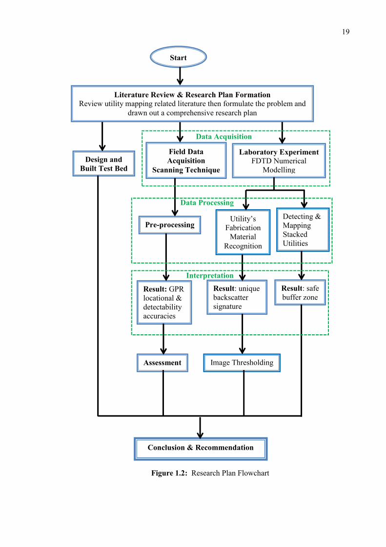
1.6 Research Design
Before developing the research plan, a thorough review of the literature was
conducted to understand the current trends of utility mapping, in order to figure out
research needs in the utility industry. From the review, four main stages of procedure
were scheduled for implementation: (i) design and built test site; (ii) investigate effects
of GPR data acquisition approaches on locational accuracy and detectability of
subsurface utility features; (iii) characterised GPR backscatter for material recognition,
and (iv) detect and map stacked utilities. Figure 1.2 depicts a flowchart indicating an
overview of the sequence of research methodology in implementing these four main
stages of the procedure.
Based on the review, test site which allows absolute calibration of GPR system,
was found to be particularly pertinent to current mapping application for testing the
performance of the GPR equipment in terms of its locational accuracy and detectability.
With this regard, a GPR test site which contains unique advantages, which can overcome
the shortcoming of existing test site is designed and built in this research. Then, field
data was acquired using dual frequencies GPR system at the test sites with both lab
controlled and in-situ environments with different system and scene parameter settings.
The optimal value obtained in the lab was then adopted for in-situ measurement. The
same parameter was also used for reconstruction of theoretical data through numerical
modelling like FDTD, to verify the results of the research. These data were subsequently
subjected to pre-processing, and followed by interpretation. Feature detection was done
to determine real reflection of each buried utility through the hyperbola reflection
illustrated in the radargram. These GPR backscatter with proper treatment can then yield
unique backscatter signature for recognition of utility’s fabrication material, thereby
opening a new facility, in addition, to current utility detection and localization facility.
Consequently, three new main finding were contributed from this research:
i) The locational accuracy and detectability of subsurface utility features using
GPR in utility mapping are directly proportional to the data acquisition scanning
18
techniques. The rarely practiced scanning technique, ‘Along-pipe’ scanning
produces the best locational and detectability accuracies of + 0.10 m equivalent
to Quality Level A utility data;
ii) Unique backscatter signature yielded from appropriate treatment is beneficial for
recognition of utility’s fabrication material, thereby, opening new facilities for
GPR application in subsurface investigations addition to current GPR utility
detection and localization; and
iii) The locational and detectability error trend and constraints of GPR
measurements within crowded (such as in horizontal and vertically stacked)
subsurface utility infrastructures yield a “best practice” procedure for
determining the safe buffer zone for maintenance works; which is crucial
aspects in installation of new utility infrastructure and detecting aging utility.
This space intentionally left blank
19
Figure 1.2: Research Plan Flowchart
Literature Review & Research Plan Formation
Review utility mapping related literature then formulate the problem and drawn out a comprehensive research plan
Start
Detecting & Mapping Stacked Utilities
Utility’s Fabrication
Material Recognition
Image Thresholding
Design and
Built Test Bed
Field Data
Acquisition
Scanning Technique
Laboratory Experiment
FDTD Numerical Modelling
Pre-processing
Assessment
Conclusion & Recommendation
Result: GPR locational & detectability accuracies
Result: safe buffer zone
Result: unique backscatter signature
Data Acquisition
Data Processing
Interpretation
20
1.7 Organization of the Thesis
The theme of thesis is reconstruction of ground penetrating radar backscatter for
subsurface utility features in utility mapping. The backscatter of the subsurface utility
feature which recorded by the GPR were reconstructed using different settings of (i)
system parameter- instrument’s frequencies (250 MHz and 700 MHz) and data
acquisition scanning techniques; and (ii) scene parameter- various types of utility
features that commonly used in current industry (water pipe, electrical cable, gas and
sewer pipe), utility’s fabrication material (mild steel, ductile iron, Polyvinyl chloride,
medium and high density polyethylene), utility’s position and depth, and commonly used
construction host material (sand, loam, rock etc.). The overview of the research
procedures involved for the successful implementation of the work were enumerates in
the following thesis structure:
Chapter 1: Introduction to background of this research, problems currently faced by the
utility mapping industries, the objective for achieving the aims of this research, the
scopes of research, and overview of the research plan as well as the thesis structure
which highlighted the importance, needs, value and urgency of this research to be
conducted.
Chapter 2: Explanation to GPR calibration test site. A field-based test site is designed
and built to understand the scanning mechanism and data formation of any frequencies
GPR system that commercially available on the market. The steps involved in the
construction of the test site and the benefits derived from this test site are clearly
explained in this chapter.
Chapter 3: GPR data acquisition is the key parameter to determine the quality level and
interpretation results of the utility data. The importance of securing reliable locational
information of the buried utilities to avoid “blind” excavation and third party’s utility
pipeline damages was highlighted through materials and methods used to examine and
21
analyse the GPR data acquisition approaches effect on locational and detectability
accuracies. The main findings of this research indicating that GPR locational and
detectability accuracies for utility mapping are directly proportional to the data
acquisition scanning techniques is derived from this chapter.
Chapter 4: Utility’s fabrication material recognition is mistaken by current utility
mapping industries as one of the impossible application. The industry defined that
application of GPR in the investigation of subsurface heterogeneities such as sandstone,
rock, utility features and tunnels are only limited to extract geometry properties. On the
contrary, this is one of the foremost GPR capabilities which need to be discovered as the
GPR backscatter with appropriate treatment can yield unique backscatter signature for
recognition of its inherent radiometry properties. Therefore, this research was conducted
to exploit research gap in utility mapping industries focusing on utility’s fabrication
material recognition using GPR backscatter. This chapter enumerates in details the
research procedure to achieve utility’s fabrication material recognition, hence,
contributing a new platform for valuable addition to current GPR application for utility
mapping.
Chapter 5: Detecting and mapping stacked subsurface utilities is an application that
must be examined in current utility mapping industry. More and more utility pipeline
are being accommodate randomly stacked in both vertical and horizontal direction in the
shallow subsurface. This causes utility congestion in subsurface, hence, leading to
difficulties in assessing the location or condition of the buried utility pipelines. In this
context, the “best practice” procedure which implemented in this chapter comprising of
data reconstruction, interpretation, and assessment for yielding a safe buffer zone for
utility maintenance work is essential for eliminating the locational and detectability
constraints and error trend of GPR measurement within utility congestion condition.
Chapter 6: Conclusions and recommendations chapter summarised all the conclusions
obtained in aforementioned chapters and highlighted recommendations which would be
beneficial for future research based on these conclusions.
183
REFERENCES
Aggrawal, N. and Karl, W.C. (2006). Line Detection In Images Through Regularized
Hough Transform. IEEE trans. on Image Processing. 15 (3): 582-590.
Ahmet, B. Y. and Mehmet S. (2011). A Least Squares Approach to Buried Object
Detection Using Ground Penetrating Radar. IEEE Sensors Journal. 11 (6): 1337-
1341.
Al-Nuaimy,W., Huang,Y., Nakhkash, M., Fang, M.T.C., Nguyen, V.T. and Eriksen, A.
(2000). Automatic Detection of Buried Utilities and Solid Objects with GPR
Using Neural Network and Pattern Recognition. Journal of Applied Geophysics.
43 (2-4): 157-165.
Amarsaikhan, D., Blotevogel, H. H., Van Genderen, J. L. and Ganzorig, M. (2009).
Knowledge Acquisition on Urban Land Cover Features Using TerraSAR and
Quickbird Images. 30th Asian Conference on Remote Sensing (ACRS 2009). 18 –
23 October. Beijing, China, 614-619.
American Association of State Highway and Transportation Officials (AASHTO).
(2004). Right of Way and Utilities Guidelines and Best Practices. Strategic Plan
4-4. American Association of State Highway and Transportation Officials, U.S.
American Society of Civil Engineering (ASCE). (2002). Standard Guideline for the
Collection and Depiction of Existing Subsurface Utility Data. ASCE Code and
Standards Activity Committee (CSAC), New York, 4-6.
184
Angelis, K. M. D. (2007). Measurement of Soil Moisture Content By Gravimetric
Method, Jan 2007, 1-2.
Annan, A.P. (1993). Practical Processing Of GPR Data. Proceeding of the Second
Government Workshop on Ground Penetrating Radar. October 1993. Columbus,
Ohio.
Annan, A.P. (2005). Ground Penetrating Radar, In: Butler, D. K. (Ed.), Society of
Exploration Geophysicists, (pp. 357-438) USA: Tulsa.
Annan, A.P. and Cosway, S. (1991). Ground Penetrating Radar Survey Design.
Proceeding of 53rd Annual Meeting of the European Association Of Exploration
Geophysicists. Florence, Italy.
Ariaratnam, S. T. (2010). Survey Questionnaire Results of the Current Level of
Knowledge on Trenchless Technologies in China. Journal of Tunnelling and
Underground Space Technology. 25 (6): 802-810.
Aydin, C. C. (2008). Usage of Underground Space for 3D Cadastre Purpose and Related
Problems in Turkey. Sensor. 8: 6972-6983.
Baker, G. S., Jordan, T. E. and Pardy, J. (2007). An Introduction to Ground Penetrating
Radar (GPR). Geological Society of America Special Papers. 432 (01), 1-18.
Balaogun, A. L., Matori, A. N. and Lawal, D. U. (2011). Developing a Framework for
the 3D Visualization of underground petroleum pipelines. International Journal
of Chemical and Environment Engineering. 2(2), 1-5.
Beck, A.R., Fu, G., Cohn, A.G., Bennett, B. and Stell, J.G. (2007). A Framework for
Data Intergration in the UK. In: Rumor, M., Coors, V. and Fendel, E.M., (eds.)
Urban and Regional Data Management: UDMS 2007. 26th Urban Data
Management Symposium. 10-12 October. Stuttgart, Germany, 261-276.
185
Bello, Y. I. and Md. N. Kamarudin. (2012a). Mapping Biogenic Gas Concentration of
Pontian Peatland, Southwest Malaysia with Ground Penetrating Radar.
International Journal of Physical Sciences, 7(8), 1187-1197.
Bello, Y. I. and Md. N. Kamarudin. (2012b). Interpretation of Ground Penetrating Radar
Image Using Digital Wavelet Transform. Asian Journal of Applied Science, 5(3),
174-182.
Bernold, L. (2003). Economic Model to Optimize Underground Utility Protection.
Journal of Construction Engineering and Management, 129(6), 645-652.
Bradford, J. H. (2011). Frequency Dependent Attenuation of GPR Data as a Tool for
Material Property Characterization: A Review and New Developments.
Proceedings of 6th International Workshop on Advanced GPR (IWAGPR 2011).
22-24 June. Aachen, Germany, 1-4.
Burton, B. L., Olhoeft, G. R. and Powers, M. H. (2004). Frequency Spectral Analysis
10th International Conference on Ground Penetrating Radar. 21 – 24 June. Delft,
The Netherland, 267-270.
Cai, J. and McMechan, G.A. (1995). Ray-Based Synthesis Of Bistatic Ground-
Penetrating Radar Profiles. Journal of Geophysics. 60 (1), 87–96.
Carlos, M. C., Clemente, C. S., Mario, F. P., Salvador, G. G., Amelia, R. B., Rafael, G.
M., Faize, A. and Driouach, A. (2011). GPR Survey at the Archaeological
Roman Site of Ciavieja, El Ejido (Spain). Proceeding of 6th International
Workshop on Advanced Ground Penetrating Radar (IWAGPR). 22-24 June.
Aachen, Germany, 1-4.
Capineri, L., Grande, P. and Temple, J. (1998). Advanced Image-processing Technique
for Real-time Interpretation of Ground-Penetrating Radar Images. International
Journal of Imaging Systems and Technology. 9 (1), 51-59.
186
Carvalho, A.A., Rebello, J.M.A., Souza, M. P. V., Sagrili, L. V. S. and Soares, S. D.
(2008). Reliability of Non-destructive Test Techniques in the Inspection of
Pipelines Used In the Oil Industry. International Journal of Pressure Vessels and
Piping. 85 (2008), 745-751.
Cassidy, N. J. and Milington, T. M. (2009). The Application of Finite-Difference Time-
Domain Modelling For the Assessment of GPR in Magnetically Lossy Materials.
Journal of Applied Geophysics. 67(4), 296-308.
Chen, D. L., Huang, C.L. and Su, Y. (2004). An Integrated Method of Statistical Method
and Hough Transform For GPR Targets Detection And Location. Acta
Electronica Sinica. 32 (9), 1468-1471.
Chen, Z. and Wang, Y. (2005). The Planning of City Underground Space. Nan Jing,
South East University Press (in Chinese).
Cheng, Z., Chen, Z. and Yang, X. (2011). The Study about the Integrated Planning
Theory of Surface And Underground Urban Space. 2011 International
Conference on Green Buildings and Sustainable Cities. 15-16 September.
Bologna, Italy: Proceeding Engineering, 16-23.
Cist, D. B. and Schutz, A. E. (2001). State of The Art for Pipe & Leak Detection.
Geophysical Survey System, Inc, Salem, New Hampshire, USA, 2-8.
Common Ground Alliance. (1999). “Study of One-Call systems and Damage Prevention
Best Practices” Sponsored by the United States Department of Transportation;
Research and Special Programs Administration; Office of Pipeline Safety, as
authorized by the Transportation Equity Act of 21st Century(TEA 21). Retrieved
on May 2012 from: http://www.commongroundalliance.com
Conyers, L. B. (2004). Moisture And Soil Differences As Related To The Spatial
Accuracy Of GPR Amplitude Maps At Two Archeological Test Sides. 10th
International Conference on Ground Penetrating Radar. 21 – 24 June. Delft, The
Netherland, 1-5.
187
Costello, S. B., Chapman, D.N., Rogers, C. D. F. and Metje, N. (2007). Underground
Asset Location and Condition Assessment Technologies. Journal of Tunnelling
and Underground Space Technology. 22(2007), 524-542.
Crocco, L., Soldovieri, F., Millington, T. and Cassidy, N. (2010). Bistatic GPR Imaging
for Incipient Pipeline Leakage Evaluation. Progress in Electromagnetics
Research, 101 (2010), 307-321.
Crocco, L., Prisco, G., Soldovieri, F. and Cassidy, N. J. (2007). Advanced Forward
Modeling And Tomograghic Inversion For Leaking Water Pipes Monitoring.
Proceeding of the IV International Workshop on Advanced Ground Penetrating
Radar (IWAGPR2007), 27-29 June. Naples, Italy, 127-131.
Cui, Y. A., Wang, L. and Xiao, J. P. (2010). Automatic Feature Recognition for GPR
Image Processing. World Academy of Science, Engineering and Technology. 61
(2010), 176-179.
Daniels, D.J. (2004). Ground Penetrating Radar. (2nd ed.) London, UK. Institution of
Electrical Engineers. 625-634. 726.
Daniels, J., Ehsani, M. R. and Allerd, B. J. (2008). Ground-Penetrating Radar Methods
(GPR). Taylor and Francis Group, LLC, USA, 129-145.
Department of Survey and Mapping Malaysia (JUPEM), (2006). Standard Guideline for
Undeground Utility Mapping. Department of Survey and Mapping Malaysia,
Kuala Lumpur, Malaysia, 4-7.
Dérobert, X. And Abraham, O. (2000). GPR And Seismic Imaging In A Gypsum
Quarry. Journal of Applied Geophysics. 45 (3), 157-169.
Dieter S. (1974). Digital Geometric Picture Correction using a Piecewise Zero- Order
Transformation. Remote Sensing of Environment. 3(4), 261-283.
188
Doctor, R.H., Dunker, N.A. and Santee, N.M. (1995). Third-party Damage Prevention
Systems. Nicor Technologies, Final Report for Gas Research Institute, INGAA
Foundation, Inc., Naperville. Contract No. 5094-810-2870.
Dror A. and Klara K. (2009). Geometric Pattern Matching For Point Sets in The Plane
Under Similarity Transformation. Information Processing Letters. 109 (16), 935-
940.
Economic Planning Unit (EPU). (2006). Ninth Malaysia Plan. EPU, Malaysia, 395-413
Economic Planning Unit (EPU). (2010). Tenth Malaysia Plan. EPU, Malaysia, 286-291
Energy Commission. (2010). Interim Report on the Performance of the Electricity
Supply Services in Malaysia. Energy Commission, Putrajaya, Malaysia, 32-35.
Enes, Y., Sevket, D. and Caner, O. (2010). On the Imaging Application of Ground
Penetrating Radar. 20th International URSI Symposium on Electromagnetic
Theory. 16-19 August. Berlin, Germany, 253-256.
Erik, M. J. and Jefferey, E. M. (1994). Three-Dimensional Ground Penetrating Radar
Imaging Using Synthetic Aperture Time-Domain Focusing. Proceedings of the
Advanced Microwave and Millimeter-Wave Detectors. 25-26 July. San Diego,
California: SPIE, 205-214.
Estimating Soil Texture: Sand, Silt or Clayey. Retrieved on Dec 2012 from,
http://www.cmg.colostate.edu/gardennotes/214.html
Faezeh, S. A. G. and Abrishamian, M.S. (2007). A Novel Method For FDTD Numerical
GPR Imaging Of Arbitrary Shapes Based On Fourier Transform. Journal NDT &
E International. 40 (2), 140-146.
Falak, R. E. (1998). GPR Investigation At Two Prehistoric Chert Mining Quarry Sites In
The Northern Madison Range, Southwestern Montana. Proceeding of the 7th
189
International Conference on Ground Penetrating Radar (GPR’98). 27-30 May.
Kansas, USA: RSRSL University of Kansas.
Francke, J. (2011). A Review of Selected Ground Penetrating Radar Application to
Mineral Resources Evaluation. Journal of Applied Geophysics. 81 (Jun 2012),
29-37.
GeoSpec LLC (2002). “Subsurface Utility Engineering (SUE)”. Retrieved on Dec 2012
from, http://www.geospecllc.com/downloads/SUE_white_paper.PDF
Gethin, W. R., Hancock, C., Ogundipe, O., Meng, X. L., Taha, A. and Montillet, J. P.
(2007). Positioning Buried Utilities using an integrated GNSS approach,
International Global Navigation Satellite System Society. IGNSS Symposium
2007. 4 – 6 December. The University of New South Wales, Sydney, Australia,
1-13.
Giannopoulos, A. (2005). Modelling Ground Penetrating Radar by GprMax. Journal of
Construction and Building Materials. 19 (10), 755-762.
Gonҫalves, H., Gonҫalves, J.A. and Luís C. (2006). Measurement for an Objective
Evaluation of the Geometric Correction Processing Quality. IEEE Geoscience
and Remote Sensing Letters. 6(2), 292-296.
Goodman, D.J. (1994). Ground -Penetrating Radar Simulation in Engineering and
Archaeology. Journal of Geophysics. 59 (2), pp243-232.
Gordon, M. O., Broughton, K. and Hardy, M.S.A. (1998). The Assessment of the Value
of GPR Imaging of Flexible Pavements. Journal of NDT & E International.
31(6), 429-438.
Grandjean, G., Gourry, J.C. and Bitri, A. (2000). Evaluation of GPR Technique for
Civil-Engineering Applications: Study on a Test Site. Journal of Applied
Geophysics. 45 (3), pp. 141-156.
190
Ground-Penetrating Radar. Retrieved on 28 October 2009. from
http://www.cflhd.gov/agm/geoApplications/SurfaceMethods/943GroundPenetrati
ngRadar.htm
Ground Penetrating RADAR (GPR). Retrieved on 15 November 2009. from
http://www.geo-sense.com/GPRmore.htm
Ground Penetrating Radar Antennas, Retrieved on May 2012 from:
http://www.geophysical.com/antennas.htm
Hao, T., Rogers, C.D.F., Metje, N., Chapman, D.N., Muggleton, J.M., Foo, K.Y., Wang,
P., Pennock, S.R., Atkins, P.R., Swingler, S.G., Parker, J., Costello, S.B.,
Burrow, M.N.P., Anspach, J.H., Armitage, R.J., Gohn, A.G., Goddard, K.,
Lewin, P.L., Orlando, G., Redfern, M.A., Royal, A.C.D. and Saul, A.J. (2012).
Condition Assessment of The Buried Utility Service Infrastructure. Journal of
Tunnelling and Underground Space Technology. 28 (March 2012), 331-344.
Hashim, M., Jaw, S. W. and Maged, M. (2010). Subsurface Utility Mapping for
Underground Cadastral Infrastructure. 31st Asian Conference on Remote Sensing
(ACRS 2010). 1 – 5 November. Hanoi, Vietnam, 1200-1206.
Hashim, M., Jaw, S. W. and Maged, M. (2011). Ground Penetrating Radar Data
Processing for Retrieval of Utility Material Types and Radius Estimation. 2011
IEEE International RF and Microwave (RFM 2011). 12 – 14 December.
Seremban, Malaysia, 191-196.
He, Y. and Hiroshi, M. (2007). Echo Extraction Method for Ground Penetrating Radar.
PIERS Online. 3(5), 701-703.
Heinrich, J. (1996). Assessment of the Cost of Underground Utility Damages. Technical
Report, North Carolina State University, USA.
Hong Kong Institute of Utility Specialists (2011). Work Procedure for Utility Mapping
by Non-destructive Methods. Utility Training Institute, Hong Kong, 1-12.
191
Hunt, D. U. L., Nash, D. and Rogers, C. D. F. (2012). Sustainability Utility Placement
via Multi-Utility Tunnels. Journal of Tunnelling and Underground Space
Technology. In Press.
Ingegneria dei Sistemi S.p.A. (2007). DETECTOR DUO System User Manual. IDS
Ingegneria Dei Sistemi, Pisa, Italy, 6-7.
Irving, J. and Knight, R. (2003). Removal of Wavelet Dispersion from Ground-
Penetrating Radar Data. Journal of Geophysics. 68(3), 960-970.
Irving, J., and Knight R. (2006). Numerical modelling of ground-penetrating radar in 2-
D using MATLAB. Journal of Computers & Geosciences. 32(9), 1247-1258.
James, H. A. (2003). New National Utility Standards & Guidelines from AASHTo, ASCE
and FHWA. So-Deep, Inc, Manassas Park, Virginia, 1-6.
Jamil, H., Nomanbhoy, Z. and Mohd Yusoff, M. Y. (2012). Underground Utility
Mapping & its Challenges in Malaysia, FIG Workshop Week 2012. 6-10 May.
Rome, Italy.
Jankiraman, M., Wessels, B. J. and Van Genderen, P. (2000a). PANDORA
Multifrequency FMCW/SFCW Radar. International Radar Conference 2000. 7-
12 May. Hllton Alexandria Mark Center, Alexandria: IEEE, 750-757.
Jankiraman, M., De Jong, E. W. and Van Genderen, P. (2000b). Ambiguity Analysis Of
PANDORA Multifrequency FMCW/SFCW Radar. International Radar
Conference 2000. 7-12 May. Hllton Alexandria Mark Center, Alexandria: IEEE,
35-41.
Jaw, S.W., Hashim, M., and Maged, M. (2010). New Approach for Extraction of
Subsurface Cylindrical Pipe Diameter and Material Type from Ground
Penetrating Radar Image. 31st Asian Conference on Remote Sensing (ACRS
2010). 1 – 5 November. Hanoi, Vietnam, 1187-1193.
192
Jaw, S.W. and Hashim, M. (2011a). Detection and Mapping of Subsurface Utility Using
Ground Penetrating Radar. 32nd Asian Conference on Remote Sensing (ACRS
2011). 3 – 7 October. Taipei, Taiwan, 502-507.
Jaw, S.W. and Hashim, M. (2011b). Accuracy of Data Acquisition Approached with
Ground Penetrating Radar for Subsurface Utility Mapping. 2011 IEEE
International RF and Microwave (RFM 2011). 12 – 14 December. Seremban,
Malaysia, 40-44.
Jaw, S.W. and Hashim, M. (2012). Ground Penetrating Radar Backscatter For
Underground Utility Assets Material Recognition. 33rd Asian Conference on
Remote Sensing (ACRS 2011). 26-30 November. Pattaya, Thailand.
Jaw, S.W. and Hashim, M. (2013). Locational Accuracy of Underground Utility
Mapping Using Ground Penetrating Radar. Journal of Tunnelling and
Underground Space Technology. 35 (April 2013), 20-29.
Jeng, Y., Lin, C. H., Li, Y. W., Chen, C. S. and Yu, H.M. (2011). Application of Sub-
image Multi-resolution Analysis of Ground Penetrating Radar Data in a Study of
Shallow Structure. Journal of Applied Geophysics. 73(3), 251-260.
Jeong, H. S., Halpin, D. W. and Bernold, L. E. (2003). Imaging and Locating Buried
Utilities. Final Report, Purdue University, West Lafayette, Indiana, 1-5.
Jol, H. M. (2009). Ground Penetrating Radar: Theory and Application. (1st ed.),
Netherlands, UK, Elsevier Science, 141-172.
Jorge, L. P., Slob, E., Robson, S. L. and Leite, D. N. (2010). Comparing Detection and
Location Performance of Perpendicular and Parallel Broadside GPR Antenna
Orientation. Journal of Applied Geophysics. 70 (1), 1-8.
Kim, J.H., Cho, S.J. and Yi, M.J. (2007). Removal of Ringing Noise in GPR Data By
Signal Processing. Journal of Geosciences. 11(1), 75-81.
193
Koo, D. H. and Ariaratnam, S. T. (2006). Innovative Method for Assessment of
Underground Sewer Pipe Condition. Journal of Automation in Construction.
15(4), 479-488.
KPUP. (2006). Standard Guidline for Underground Utility Mapping 1/2006. Retrived
Nov 2012, from http://www.jupem.gov.my/JupemGeoportal/bm/pekeliling.aspx
Lahouar S. (2003). Development of Data Analysis Algorithms for Interpretation of
Ground Penetrating Radar. Doctor of Philosophy. Faculty of the Virginia
Polythechnic Institute and State University, Blacksburg, Virginia.
Lester, J. and Bernold, L.E. (2007). Innovative Process to Characterize Buried Utilities
Using Ground Penetrating Radar. Journal of Automation in Construction. 16 (4),
546-555.
Lew, J. J. (2001). Evaluation Of The Performance Of Subsurface Utility Engineering As
A Design Cost Reduction Tool. CIB World Building Congress. 2-6 April.
Wellington, NewZealand, 1-8.
Liu, S. X., Zeng, Z. F and Deng L. (2007). FDTD Simulation For Ground Penetrating
Radar In Urban Application. Journal of Geophysics and Engineering. (4), pp.
262-267.
Liu, Y. Y., Wang, M. Q. And Cai, Q. R. (2010). The Target Detection of GPR Images
Based on Curve Fitting. 2010 3rd International Congress on Image and Signal
Processing (CISP2010). 16-18 October. Yantai, China, 2876 - 2879.
Lorenc, S. J., and Bernold, L. E. (1998). “Smart” Attachment for Utility Damage
Prevention. Proceeding of the ASCE Specialty Conference on Robotics for
Challenging Environments. 26 February – 3 March. Albuquerque, New Mexico:
ASCE, 140-146.
194
Lunt, I.A., Hubbard, S.S., and Rubina, Y. (2005). Soil Moisture Content Estimation
Using Ground-Penetrating Radar Reflection Data. Journal of Hydrology. 307 (1-
4), 254–269.
Mapping the Underworld (MTU) (2011). Retrieved Oct 2012, from:
http://www.mappingtheunderworld.ac.uk/.
Martinez, A., and Bymes, A. P. (2001). Modelling Dielectric-Constant Values of
Geologic Materials: An Aid to Ground Penetrating Radar Data Collection and
Interpretation. Current Research in Earth Sciences. 247 (part 1), 1-16.
Metje N., Atkins, P.R., Brennan, M.J., Chapman, D.N., Lim, H.M., Machell, J.,
Muggleton, J.M., Pennock, S., Ratcliffe, J., Redfern, M., Rogers, C.D.F., Saul,
A.J., Shan, Q., Swingler, S. and Thomas A.M. (2007). Mapping the Underworld
– State-of-The-Art Review. Journal of Tunnelling and Underground Space
Technology. 22 (5-6), 568–586.
Millington, T.M. and Cassidy, N.J. (2009). Optimising GPR Modelling: A Practical,
Multi-threaded Approach to 3D FDTD Numerical Modelling. Journal of
Computers and Geosciences. 36 (9), 1135-1144.
Motoyuki S. (2001). GPR and Its Application to Environmental Study. Center for
Northeast Asia Studies (CNEAS), Tohoku University, Sendai, Japan, 2-16.
Motoyuki, S. (2009). Principles of Mine Detection by Ground-penetrating Radar.
Springer-Verlag, London, 19-26.
Nana, R., Hendrawan, Sugihartono, Andriyan, B. S. (2009). Interpretation Target Pattern
of a Buried Basic Object on Surface Ground Penetrating radar System.
International Conference on Electrical Engineering and Informatics. 5-7 August.
Selangor, Malaysia, 553-558.
Neal, A. (2004). Ground-Penetrating Radar and Its Use in Sedimentology: Principle,
Problems and Progress. Journal of Earth Science Reviews. 66 (3-4), 261-330.
195
New Hemisphere Department of Transportation. (2010). Utility Accommodation Manual.
New Hemisphere Department of Transportation, New Hemisphere 9-10.
Ni, S. H., Huang, Y. H., Lo, K.F. and Lin, D.C. (2010). Buried Pipe Detection by
Ground Penetrating Radar Using the Discrete Wavelet Transform. Journal of
Computers and Geotechnics. 37(4), 440-448.
Olhoeft, G. R. (2001). GRORADARTM, Acquisition, Processing, Modeling and Display
of Dispersive Ground Penetrating Radar Data, version 2001.01.
Olver, A. D., Cuthbertt, L. G., Nicolaides, M., Curr, A. G. (1982). Portable FMCW
Radar for Locating Buried Pipes. Proceeding of IEEE Conference Radar 82. 18-
20 October. London, UK, 413-418.
Orlando, J. T., and Rui, S. (2002). Image Segmentation by Histogram Thresholding
using Fuzzy Sets. IEEE Transaction on Image Processing. 11(12), 1457-1465.
Ozdemir, C., Lim, S. K. and Ling, H. (2004). A Synthetic-Aperture Algorithm for
Ground Penetrating Radar Imaging. Microwave and Optical Technology Letters.
42 (5), 412-414.
Pasolli, E., Melgani F. and Donelli M. (2009). Automatic Analysis of GPR Images: A
Pattern-Recognition Approach. IEEE Transaction on Geoscience and Remote
Sensing. 47 (7), 2206-2217.
Reeb, J. and Milota, M. (1999). Moisture Content by the Oven-Dry Method for Industrial
Testing. Oregon State University, Corvallis, WDKA, 66-74.
Reppert, P. M., Morgan, F. D. and Toksӧz, M. N. (2000). Dielectric Constant
Determination Using Ground-Penetrating Radar Reflection Coefficient. Journal
of Applied Geophysics. 43 (2-4), pp. 189-197.
Reyes, C., Hilaire, T., Paul, S. and Mecklenbräuker, C. F. (2010). Evaluation of the Root
Mean Square Error Performance of the PAST-Consensus Algorithm. In: 2010
196
International ITG Workshop on Smart Antennas. 23-24 February. Bremen,
Germany, 156 – 160.
Ristic, A. V., Petrocacki, D. and Govedarica, M. (2009). A New Method to
Simultaneously Estimate the Radius of a Cylindrical Object and the Wave
Propagation Velocity from GPR Data. Journal of Computers and Geosciences.
35 (8), 1620-1630.
Robinson, L. A., Weir, W. B., and Young, L. (1974). Location and Recognition of
Discontinuities in Dielectric Media Using Synthetic RF Pulses. Proceeding of the
IEEE. 42(1), 36-44.
Roger, C. D. F. Chapman, D. N., Entwisle, D., Jones, L., Kessler, H., Metje, N., Mica,
L., Morey, M., Pospisil, P., Price, S., Raclavsky, J., Raines, M., Scott, H. and
Thomas, A.M. (2009). Predictive Mapping of Soil Geophysical Properties for
GPR Utility Location Surveys. 5th International Workshop on Advanced Ground
Penetrating Radar. 27-29 May. Granada, Spain, 60-67.
Rogers, C.D.F., Hao, T., Costello, S.B., Burrow, M.N.P., Metje, N., Chapman, D.N.,
Parker, J., Armitage, R.J., Anspach, J.H., Muggleton, J.M., Foo, K.Y., Wang, P.,
Pennock, S.R., Atkins, P.R., Swingler, S.G., Gohn, A.G., Goddard, K., Lewin,
P.L., Orlando, G., Redfern, M.A., Royal, A.C.D. and Saul, A.J. (2012). Condition
Assessment of the Buried Utility Service Infrastructure- A Proposal for
Integration. Journal of Tunnelling and Underground Space Technology. 28 (1),
202-211.
Rubing, G. (2009). New Progress of GPR to Detect Underground Pipelines. Proceedings
of the International Conference on Pipelines and Trenchless Technology. 18-21
October. Shanghai, China, 803-809.
Schmelzbach, C., Scherbaum, F., Tronicke, J., and Dietrich, P. (2011). Bayesian
Frequency-Domain Blind Deconvolution of Ground-Penetrating Radar Data.
Journal of Applied Geophysics. 75 (4), 610-630.
197
Schofield, W. and Breach, M. (2007). Engineering Surveying: (6th ed.), UK, Elsevier
Ltd.
Seyfi, L. and Yaldiz, E. (2010). A Novel Software for an Energy Efficient GPR. Journal
of Advances in Engineering Software. 41 (10), 1195-1199.
Seyfried, D., Busche, A., Janning, R., Lars, S. T. and Schoebel, J. (2012). Information
Extraction from Ultrawideband Ground Penetrating Radar Data: A Machine
Learning Approach. 7th German Microwave Conference (GeMic). 12-14 March.
Ilmenau University of Technology Germany, Germany, 1-4.
Shihab, S. and Al-Nuaimy, W. (2005). Radius Estimation for Cylindrical Objects
Detected by Ground Penetrating Radar. Journal of Subsurface Sensing
Technologies and Applications. 6(2), 151-165.
Stinson, W. (1998). Preventing Damage to Unlocatable Infrastructure. Underground
Focus Magazine, Atlanta GA.
Technos, Inc (2001). Surface Geophysics, Retrievied on Oct 2011 from:
http://www.technos-inc.com/surface.html
Terry, L. P. (2000). Soil moisture measurement technology. University of California
Davis 1-8.
Thomas, A. M., Rogers, C. D. F., Chapman, D. N., Metje, N. and Castle, J. (2009).
Stakeholder Needs for Ground Penetrating Radar Utility Location. Journal of
Applied Geophysics. 67 (4), pp. 345-351.
Thomas, B. and Mike, E. D. (2009). Sampling Theorems for Signals from the Union of
Finite-Dimensional Linear Subspaces. IEEE Transactions on Information
Theory. 55 (4), 1872-1882.
198
Toropainen, A. P. (1995). Measurement of the Properties of Granular Materials by
Microwave Backscattering. Journal of Microwave Power and Electromagnetic
Energy. 30 (4), 240-245.
U.S. Department of Transportation, Office of Pipeline Safety, Research and Special
Programs Administration. (1999). Common Ground: Study of One-Call Systems
and Damage Prevention Best Practices. Transportation Equity Act for 21st
Century(TEA 21).
Vera, B., Boriana, V., and Christo, K. (2008). A Software Tools For GPR Data
Simulation & Basic Processing. Journal of Cybernetics & Information
Technologies. 8 (4), 1-8.
Wan Hussin, W.M.A and Mohmoud, B. A. (2011). The Design of a GPR Test Site for
Underground Utilities. PIERS Proceedings. 20-23 March. Marrakesh, Morocco,
1864-1867.
Wang, J. and Su, Y. (2011). Underground Object Detection Based on Cross Correlation
and Hough Transform. 2011 Microwave, Radar and Remote Sensing Symposium
(MRRS). 25-27 August. National Aviation University Kiev, Ukraine, 363-366.
Yee, K. S. (1966). Numerical Solution of Initial Boundary Value Problems Involving
Maxwell’s Equation in Isotropic Media. IEEE Transactions on Antennas and
Propagation. 14 (3), 302-307.
Yilmaz, O. (2001). Seismic Data Analysis: Processing, Inversion, and interpretation of
Seismic Data. Tulsa, USA, Society of Exploration Geophysicists.
Yu, X. and Zhang, X.B. (2007). Microwave Magnetic Properties of Dust and Its
Implication for Geophysics and Cohesion. NASA Advisory Council Workshop on
Science Associated with the Lunar Exploration Architecture. 27 February – 2
March. Tempe, Arizona.
199
Zeng, Y., Zhang, J. X. Van Genderan, J. L. and Zhang, Y. (2010). Image Fusion for
Land Cover Change Detection. International Journal of Image and Data Fusion.
1(2), 193-215.
Zuhaidi, M. J., Mohd Hafzi, M. I., Rohayu, S. and Wong, S. V. (2009). An Exploration
of Weather Threats to Road Safety in Tropical Country, 4rd International
Conference on ESAR “Expert Symposium on Accident Research”. 16-18
September. Hannover Medical School, Hanover, Germany 130-140.