Embed Size (px)
Citation preview

Reconstruction of Fingerprints from Minutiae
Points
by
Jidnya A. Shah
Thesis submitted to theCollege of Engineering and Mineral Resources
at West Virginia Universityin partial fulfillment of the requirements
for the degree of
Master of Sciencein
Electrical Engineering
Arun A. Ross, Ph.D., ChairXin Li, Ph.D.
Larry Hornak, Ph.D.
Lane Department of Computer Science and Electrical Engineering
Morgantown, West Virginia2005
Keywords: Minutiae template, Fingerprint individuality, Classification, Reconstruction, Gaborfilters, Streamlines, Line Integral Convolution.
Copyright 2005 Jidnya A. Shah

Abstract
Reconstruction of Fingerprints from Minutiae Points
by
Jidnya A. ShahMaster of Science in Electrical Engineering
West Virginia University
Arun A. Ross, Ph.D., Chair
Most fingerprint authentication systems utilize minutiae information to compare fingerprint im-ages. During enrollment, the minutiae template of a user’s fingerprint is extracted and storedin the database. In this work, we concern ourselves with the amount of fingerprint informationthat can be elicited from the minutiae template of a user’s fingerprint. We demonstrate thatminutiae information can reveal substantial details such as the orientation field and class of the(unseen) parent fingerprint that can potentially be used to reconstruct the original fingerprintimage.
Given a minutiae template, the proposed method first estimates the orientation map of theparent fingerprint by constructing minutiae triplets. The estimated orientation map is observedto be remarkably consistent with the underlying ridge flow of the unseen parent fingerprint. Wealso discuss a fingerprint classification technique that utilizes only the minutiae information todetermine the class of the fingerprint (Arch, Left loop, Right loop and Whorl). The proposedclassifier utilizes various properties of the minutiae distribution such as angular histograms,density, relationship between minutiae pairs, etc. A classification accuracy of 82% is obtained ona subset of the NIST-4 database. This indicates that the seemingly random minutiae distributionof a fingerprint can reveal important class information.
Furthermore, contrary to what has been claimed by several minutiae-based fingerprint sys-tem vendors, we demonstrate that the minutiae template of a user may be used to reconstructfingerprint images. Two techniques have been proposed for fingerprint reconstruction. The firsttechnique utilizes Gabor-like filters, while the second technique employs streamlines and LinearIntegral Convolution (LIC) to generate the ridge structure of the parent fingerprint. The salientfeature of the second method is its ability to generate minutiae at desired locations in the regen-erated ridge map. Experiments conducted on the minutiae templates of the NIST-4 databasechallenge the commonly held notion that minutiae points do not reveal information about theparent fingerprint.

iii
I dedicate my thesis to my family

iv
Acknowledgments
Words alone cannot fully express my gratitude and appreciation for those who guided and
supported me through these last two years. I have been fortunate to be surrounded by excellent
teachers and friends.
It was my honor to have Dr. Arun Ross as my advisor and committee chair. His complete
dedication to work, love for perfection, infectious enthusiasm, have always motivated me. My
interactions with him have been of immense help in defining my research goals and in finding
the systematic solutions to achieve them. His regular reminders of “work hard” often pushed me
to put in my best possible efforts.
I am very grateful to Dr. Xin Li and Dr. Lawrence Hornak for their valuable guidance and
suggestions for my thesis. Their comments have been very useful in enhancing the presentation
of this thesis. I would also like to extend my gratitude to all lab-mates Rohin, Sarvesh, Simona,
Pisut, Chris, Rohan and Phani who have been with me all the time and for their co-operation and
necessary feedback. I am also very thankful to Kiran for helping me to use the SDK’s of various
commercial fingerprint system products. My heartfelt thanks to the department secretaries and
the systems group for their excellent work and support.
I would like to thank my parents, sister, brother and my in laws for their support, never-
fading love and sacrifice. It was because of them I could survive hard times and be consistent
on my work. A big thanks to my husband, Samir, for understanding me, standing by me and
sharing my joys and frustrations without which I would not have come this far.

v
Contents
Acknowledgments iv
List of Figures vi
List of Tables ix
1 Introduction 11.1 Biometrics . . . . . . . . . . . . . . . . . . . . . . . . . . . . . . . . . . . . . . . . 11.2 Fingerprints . . . . . . . . . . . . . . . . . . . . . . . . . . . . . . . . . . . . . . . 41.3 Vulnerabilities of a biometric system . . . . . . . . . . . . . . . . . . . . . . . . . 6
1.3.1 Vulnerability of a biometric template . . . . . . . . . . . . . . . . . . . . . 81.4 Problem Statement . . . . . . . . . . . . . . . . . . . . . . . . . . . . . . . . . . . 131.5 Contribution of the Thesis . . . . . . . . . . . . . . . . . . . . . . . . . . . . . . . 131.6 Organization of the Thesis . . . . . . . . . . . . . . . . . . . . . . . . . . . . . . . 14
2 Estimating Ridge Orientations using Minutiae Points 152.1 Orientation Estimation Algorithm . . . . . . . . . . . . . . . . . . . . . . . . . . . 162.2 Validating the estimated orientation map . . . . . . . . . . . . . . . . . . . . . . . 22
3 Fingerprint Classification Using Minutiae Points 273.1 Fingerprint classification . . . . . . . . . . . . . . . . . . . . . . . . . . . . . . . . 27
3.1.1 Need for fingerprint classification . . . . . . . . . . . . . . . . . . . . . . . 283.1.2 Various approaches for classification . . . . . . . . . . . . . . . . . . . . . . 29
3.2 Novel use of minutiae for classification . . . . . . . . . . . . . . . . . . . . . . . . 303.2.1 Minutiae based classification algorithm . . . . . . . . . . . . . . . . . . . . 31
3.3 Analyzing classifier performance . . . . . . . . . . . . . . . . . . . . . . . . . . . . 43
4 Reconstruction of fingerprints 454.1 Synthetic fingerprint generation . . . . . . . . . . . . . . . . . . . . . . . . . . . . 454.2 Reconstructing fingerprints from minutiae points . . . . . . . . . . . . . . . . . . . 51
4.2.1 Reconstructing fingerprints using Gabor-like filters . . . . . . . . . . . . . 524.2.2 Reconstructing fingerprints using Streamlines and LIC . . . . . . . . . . . 584.2.3 Comparing two reconstruction schemes . . . . . . . . . . . . . . . . . . . . 664.2.4 Spoofing of fingerprint authentication system . . . . . . . . . . . . . . . . . 68
5 Summary and Future work 735.1 Future work . . . . . . . . . . . . . . . . . . . . . . . . . . . . . . . . . . . . . . . 75
References 77

vi
List of Figures
1.1 Various biometric identifiers. . . . . . . . . . . . . . . . . . . . . . . . . . . . . . . 21.2 A typical biometric system. . . . . . . . . . . . . . . . . . . . . . . . . . . . . . . 31.3 (a) A fingerprint with ridge ending (E) and bifurcation (B) with position (x, y)
and orientation (θ), (b) Core and delta points. . . . . . . . . . . . . . . . . . . . 41.4 Various types of attacks on a biometric system (adapted from [1]). . . . . . . . . . 71.5 Block diagram for Adler’s face regeneration algorithm. . . . . . . . . . . . . . . . 91.6 Block diagram of Hill’s fingerprint regeneration algorithm. . . . . . . . . . . . . . 111.7 (a) Original Arch, (b) Reconstructed fingerprint from minutiae points using line
drawing. . . . . . . . . . . . . . . . . . . . . . . . . . . . . . . . . . . . . . . . . . 12
2.1 (a) A fingerprint image, (b) Corresponding orientation map. . . . . . . . . . . . . 152.2 Minutiae plots of 4 fingerprint classes: (a) A, (b) W, (c) L, and (d) R. . . . . . . . 162.3 A block diagram showing main steps of orientation estimation algorithm. . . . . . 172.4 A minutiae triplet. . . . . . . . . . . . . . . . . . . . . . . . . . . . . . . . . . . . 172.5 Example of a minutiae triplet with large θdiff . . . . . . . . . . . . . . . . . . . . . 192.6 Example of a triplet with large Lmax for Arch and Whorl, (a) Correct result, (b)
Incorrect result, (c) An example of skinny triple. . . . . . . . . . . . . . . . . . . . 202.7 (a) Contained triplets, (b) Overlapping triplets. . . . . . . . . . . . . . . . . . . . 202.8 (a) Minutiae distribution of a fingerprint, (b) Examples of good (blue), with Lavg
= 112.66, Var = 5, Q = 237.63, and bad (red) with Lavg = 217, Var = 26, Q =67.55, quality triplets, (c) Estimated orientation map. . . . . . . . . . . . . . . . . 21
2.9 (a) Original Arch, (b) Triplet formation, (c) Orientation Estimation Result. . . . . 222.10 (a), (c) and (e) are original fingerprints of L, R and W whereas (b), (d) and (f)
are their estimated orientation maps. . . . . . . . . . . . . . . . . . . . . . . . . . 232.11 Comparing the estimated orientation map (from minutiae) with the true map: (a)
Minutiae plot of a fingerprint, (b) Estimated orientation map, (c) True orienta-tion map. Due to absence of valid triplets around the core region, the estimatedorientation map cannot capture these regions, e.g., the concentric pattern in whorls. 25
2.12 Correlation between θ̂ and θ as observed on the NIST 4 database. About 79% ofthe orientation pairs have correlation more than 0.75. . . . . . . . . . . . . . . . . 26
3.1 Five classes of fingerprints according to Galton-Henry classification scheme [2].Core is represented by a square whereas the delta by a circle. . . . . . . . . . . . . 27
3.2 Minutiae plots of 4 fingerprint classes: (a) A, (b) W, (c) L, and (d) R. . . . . . . 313.3 Block diagram showing main steps of minutiae-based classification algorithm. . . . 323.4 (a) and (b) show L and W fingerprints divided into various areas whereas (c) and
(d) show the corresponding original fingerprints respectively. . . . . . . . . . . . . 32

LIST OF FIGURES vii
3.5 (a) Circular plot of minutiae, (b) Line ‘L’ is perpendicular to the orientation ofminutiae m, (c) L made nearly perpendicular (± 30o) to the orientation θ. . . . . 33
3.6 Minutiae plot overlaid on original fingerprint of A, L and W are shown in (a), (c)and (e) respectively. The corresponding R0 points marked in blue (‘X’) detectedusing estimated orientation maps are shown in (b), (d) and (f). . . . . . . . . . . . 35
3.7 (a) The orientation map and detected registration point marked in blue (‘*’), (b)Salient minutiae in a 300× 300 frame about R0. . . . . . . . . . . . . . . . . . . . 36
3.8 Rose plots of (a) A, (b) W, (c) L, (d) R. . . . . . . . . . . . . . . . . . . . . . . . 373.9 A whorl minutiae plot showing 4 types of minutiae pairs. . . . . . . . . . . . . . . 383.10 Minutiae density associated with 4 different classes of fingerprints: (a) A, (b) W,
(c) L, and (d) R. These plots were generated using 30 images per class. Blueindicates a low density region while red indicates a high density region. . . . . . . 39
3.11 Kernel for (a) L, (b) R, and (c) W. . . . . . . . . . . . . . . . . . . . . . . . . . . 403.12 Red Vector: Unit tangent vector to the kernel, Green Vector: Direction of flow
field at point γt [3]. . . . . . . . . . . . . . . . . . . . . . . . . . . . . . . . . . . . 413.13 Small inter-class variability between classes L and T (a) R and W, (b) and large
intra-class variability between two prints of whorl class (c) and (d). . . . . . . . . 433.14 Atypical minutiae plot of a fingerprint of R class. . . . . . . . . . . . . . . . . . . 44
4.1 The process used by SFINGE to generate fingerprints: (a) Fingerprint shape gen-eration, (b) Orientation image for a given set of core and delta points, (c) Outputwhite image initialized with random seeds, (d) Generation of ridge pattern andminutiae initiated from seed points, (e) Synthetic L fingerprint, (f) Synthetic fin-gerprint with noise. (All figures are generated using SFINGE software). . . . . . . 50
4.2 Block diagram showing the main stages of our reconstruction algorithm. . . . . . . 534.3 (a) Image block initialized with seeds, (b) A Gabor filter tuned to 45o, (c) Gener-
ated ridge pattern, (d) Image block initialized with seeds, (e) A Gabor filter tunedto 191o, (f) Generated ridge pattern. . . . . . . . . . . . . . . . . . . . . . . . . . 54
4.4 Fingerprint reconstruction: (a) Estimated orientation field for a L fingerprint, (b)Ridge generation after 1 iteration, (c) Ridge generation after 10 iterations, (d)Reconstructed ridge pattern after 25 iterations, (e) Original L fingerprint. . . . . 55
4.5 (a) Estimated Orientation Map θ̂, Output of ridge generation with (b) σ = 0.2,(c) σ = 1.2, (d) σ = 2, (e) Original fingerprint for classes A, L, R and W. . . . . 56
4.6 Output of ridge generation with (a) D = 0.1, (b) D = 0.2, (c) D = 1/σ, (d)D = 5, (e) D = 10, (f) D = 20. . . . . . . . . . . . . . . . . . . . . . . . . . . . . 57
4.7 (a) Estimated orientation map θ̂ , (b) Reconstructed fingerprint, (c) Originalfingerprint of T, R, and W respectively. . . . . . . . . . . . . . . . . . . . . . . . 57
4.8 Block diagram showing visualizing vector field using LIC. . . . . . . . . . . . . . . 594.9 Block diagram showing the main stages of the proposed fingerprint reconstruction
algorithm. . . . . . . . . . . . . . . . . . . . . . . . . . . . . . . . . . . . . . . . . 594.10 (a) A streamline S tangent to orientation field θ̂, (b) Streamline originating from
a seed point (x, y) in the vector field θ̂ . . . . . . . . . . . . . . . . . . . . . . . . 604.11 (a) Estimated orientation map θ̂ with border points marked in ‘red’ color, (b)
Streamlines generated from minutiae points as seed points, (c) Streamlines gener-ated using border points as seed points for classes, (d) Original fingerprint for A,R, L, W respectively. . . . . . . . . . . . . . . . . . . . . . . . . . . . . . . . . . 62

LIST OF FIGURES viii
4.12 (a) Lattice of seed points (Dseed = 10), (b) Seed points ‘S’ overlaid on the orien-tation field, θ̂, of an arch, (c) Streamline terminated near a minutia ‘m’. . . . . . 63
4.13 (a) Estimated orientation map θ̂, (b) Streamlines generated without controllingDr, (c) Streamlines generated by controlling Dr = 5, for A, R, L, W. . . . . . . . 64
4.14 (a) Minutiae plot, (b) Estimated orientation map θ̂, (c) Streamlines . . . . . . . . 654.15 Lending texture to a streamline using LIC: (a) White noise image, T, (b) Con-
volving T with a streamline, (c) Result of LIC. . . . . . . . . . . . . . . . . . . . . 664.16 (a) Estimated orientation map θ̂, (b) Result of applying LIC, (c) Enhanced fin-
gerprint using a 5× 5 lowpass filter, (d) The original fingerprint. . . . . . . . . . . 674.17 .9513.6(a) Minutiae plot, (b) Estimated orientation map θ̂, (c) Regenerated fingerprint using Gabor filters, (d) Regenerated fingerprint
using LIC . . . . . . . . . . . . . . . . . . . . . . . . . . . . . . . . . . . . . . . . . . 674.18 .9513.6Overlay of original (magenta) and reconstructed (blue) fingerprints for two minutiae templates. . . . . . . . . . . 684.19 (a) Original fingerprint and its minutiae plot, (b) Estimated orientation map θ̂,
(c) Result of applying LIC, (d) Enhanced ridge structure using COTS. . . . . . . 694.20 .9513.6CMC curves when class of reconstructed fingerprint is (a) unknown (matched against all fingerprints of NIST-4f database), (b)
known (matched against all fingerprints of the same class only). . . . . . . . . . . . . . . . . . . . . . . . . . 704.21 .9513.6CMC curves when reconstructed fingerprint matched against all the fingerprints in FVC2002 DB3 database). . . . . . . 714.22 Estimated orientation map θ̂ [(a), (d), (h)], Reconstructed fingerprint [(b), (e), (i)],
Enhanced image by VeriFinger and its extracted minutiae [(c), (f), (j)], Originalfingerprint [(d), (g), (k)] for 3 fingerprints of DB3 FVC2002 database. . . . . . . . 72
4.23 (a) Estimated orientation map θ̂, (b) Reconstructed fingerprint, (c) Enhancedimage by VeriFinger and its extracted minutiae, (d) Original A fingerprint ofNIST 4f Database. . . . . . . . . . . . . . . . . . . . . . . . . . . . . . . . . . . . 72
5.1 Reconstructing fingerprints using hill-climbing approach. . . . . . . . . . . . . . . 76

ix
List of Tables
3.1 Number and position of singularities in five fingerprint classes. . . . . . . . . . . . 283.2 A summary of different fingerprint classification techniques. . . . . . . . . . . . . . 303.3 Confusion matrix indicating classification performance. . . . . . . . . . . . . . . . 42
1
Chapter 1
Introduction
1.1 Biometrics
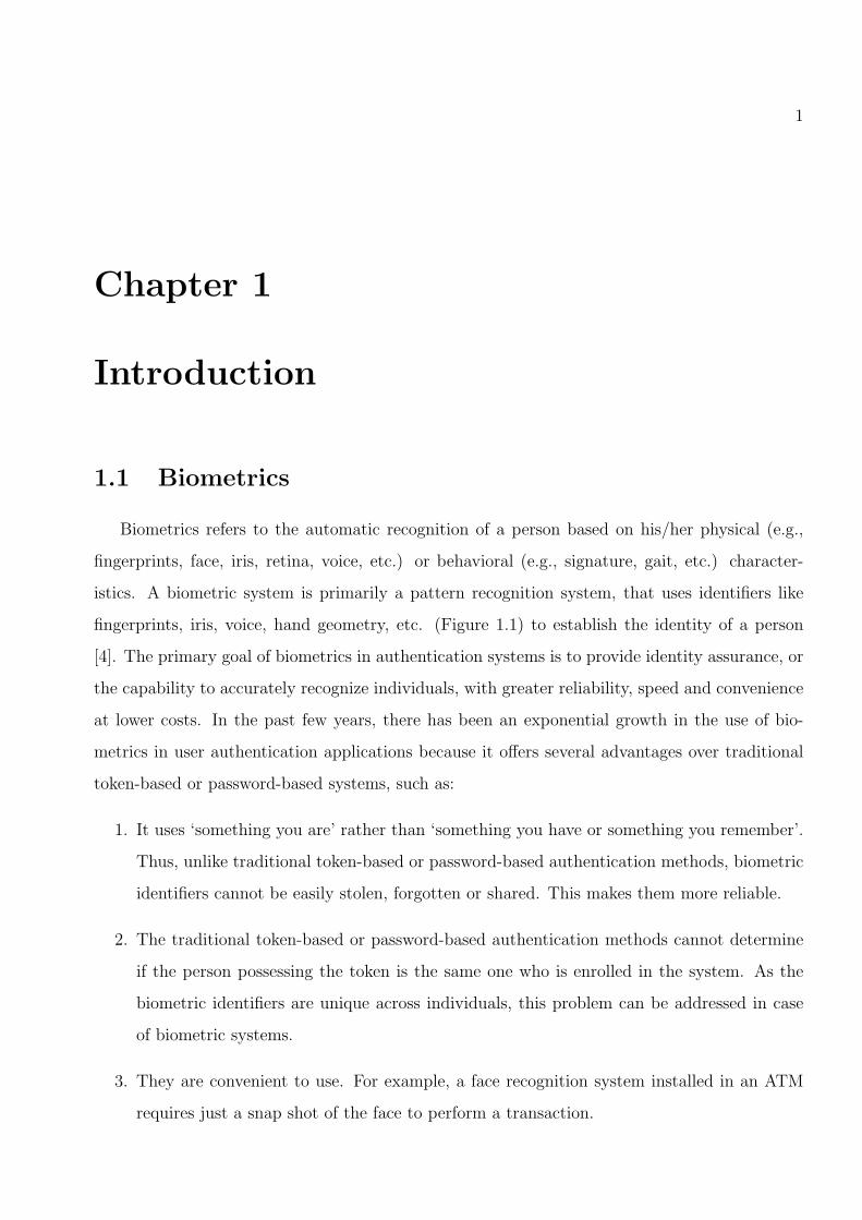
Biometrics refers to the automatic recognition of a person based on his/her physical (e.g.,
fingerprints, face, iris, retina, voice, etc.) or behavioral (e.g., signature, gait, etc.) character-
istics. A biometric system is primarily a pattern recognition system, that uses identifiers like
fingerprints, iris, voice, hand geometry, etc. (Figure 1.1) to establish the identity of a person
[4]. The primary goal of biometrics in authentication systems is to provide identity assurance, or
the capability to accurately recognize individuals, with greater reliability, speed and convenience
at lower costs. In the past few years, there has been an exponential growth in the use of bio-
metrics in user authentication applications because it offers several advantages over traditional
token-based or password-based systems, such as:
1. It uses ‘something you are’ rather than ‘something you have or something you remember’.
Thus, unlike traditional token-based or password-based authentication methods, biometric
identifiers cannot be easily stolen, forgotten or shared. This makes them more reliable.
2. The traditional token-based or password-based authentication methods cannot determine
if the person possessing the token is the same one who is enrolled in the system. As the
biometric identifiers are unique across individuals, this problem can be addressed in case
of biometric systems.
3. They are convenient to use. For example, a face recognition system installed in an ATM
requires just a snap shot of the face to perform a transaction.

CHAPTER 1. INTRODUCTION 2
RETINAL VEINS
VEINS
GAIT
FACE
EAR
SIGNATURE
HAND VEIN
FINGERPRINT
HAND GEOMETRY
VOICE
PALM PRINT
IRIS
DENTAL
Figure 1.1: Various biometric identifiers.

CHAPTER 1. INTRODUCTION 3
Biometric authentication can be used to control the security of banking transactions, personal
computers, cell phones, web access, electronic commerce, restricted premises like nuclear plants,
etc. Also it has recently been used at US airports for verifying the identity of the frequently
flying individuals at the time of immigration.
A typical biometric authentication system is illustrated in Figure 3.1. It performs the follow-
ing processing steps:
1. acquires a biometric sample,
2. extracts salient feature set (biometric template) and stores in a database,
3. compares a “live” template to previously stored templates, to calculate a match score [5].
The enrollment stage comprises of storing the template of each user in the database. Depending
on the application, a biometric system can be used for verification or identification. Identification
is also called as “one-to-many” matching. The system identifies an individual by comparing his
feature set with all the templates stored in the database. Verification refers to “one-to-one”
matching. Here an individual claims to be an enrolled user. To verify this claim, his template is
compared with the stored template of the claimed identity.
Biometric sample
Feature extraction
Template Database
Compare
Feature extraction
Match Score Decision
Biometric sample
ENROLLMENT
Biometric sample
Feature extraction
Template Database
Feature extraction
Feature Set
Match Score Decision
Biometric sample
ENROLLMENT
AUTHENTICATION
Feature Set
Figure 1.2: A typical biometric system.
CHAPTER 1. INTRODUCTION 4
1.2 Fingerprints
Among all known biometrics like iris, face, speech, hand geometry, etc., fingerprint is one of
the oldest and widely recognized biometric trait due to its attractive properties like permanence
and individuality. Fingerprints have been used in law enforcement for many years.
A fingerprint is a smoothly flowing pattern of alternating ridges and valleys. The ridges
present on the skin of the finger which makes contact with an incident surface under normal
touch are called as friction ridges [6]. The unique pattern formed by these friction ridges forms
a fingerprint. These ridges do not flow continuously but rather display various types of imper-
fections known as minutiae (minor details in fingerprints). The various types of minutiae are:
ridge ending, ridge fork, island, dot, broken ridge, bridge, spur, enclosure, delta, double fork,
bifurcation, trifurcation, etc. In all 150 minutiae types have been reported in the literature [7].
Out of all these, bifurcations and ridge endings are the most stable and robust points in fin-
gerprints [4]. The point at which a ridge terminates or, alternatively, begins is called as ridge
ending. A ridge ending is surrounded on three sides by valley. And the point at which a ridge
splits into two ridges or, alternatively, where two separate ridges combine into one is called as
bifurcation (See Figure 1.3 (a)). At the time of enrollment in a fingerprint system, important
minutiae information (typically positions of ridge endings and bifurcations and the associated
orientations) is extracted and stored in the database in the form of a template. A fingerprint
B(x,y)
E(x,y)
Core
Delta
(a) (b)
Figure 1.3: (a) A fingerprint with ridge ending (E) and bifurcation (B) with position (x, y) andorientation (θ), (b) Core and delta points.
can be also represented using two global features namely core and delta. These are also called
are called singular points. The core point is defined as the highest point on the innermost ridge,

CHAPTER 1. INTRODUCTION 5
while, the delta point is defined as the point where ridge flows having three different directions
meet as shown in Figure 1.3 (b). As minutiae representation is stable and comparatively easy,
most of the automatic fingerprints matching systems are only minutiae based. Every minutia-
based fingerprint authentication system stores minutiae information in a template and uses it
for authentication. The simplest template includes minutiae position, their type and respective
orientation. The position of a minutia is given by its x and y coordinates while its orientation,
θ is defined by the angle between the associated ridge and the horizontal axis.
The pattern of minutiae distribution in a fingerprint forms a valid representation of the finger-
print, since it is observed to vary across individuals (and across fingers of the same individual)
[8]. Typically, in a live-scan fingerprint image of good quality, approximately 40-60 minutiae
(500× 500 image size) are obtained [4]. Fingerprint matching is accomplished by comparing the
minutiae distribution of two fingerprints via sophisticated point pattern matching techniques [9].
“Two like fingerprints would be found only once 10 raised to 48 years.” [8]. Although finger-
prints have strong history of being used extensively in forensics since many years, there have not
been any scientific evidence for their distinctiveness, i.e., individuality. It is generally accepted
due to empirical results. By individuality, we mean that given a target population of the finger-
prints, the probability of getting a sufficiently similar fingerprints is very small [10]. Along with
overall ridge flow pattern, ridge frequency and location of singularities, minutiae points have been
used extensively in individuality models. Various properties of minutiae like location, direction,
type, ridge counts between pairs of minutiae, etc., contribute to fingerprint individuality.
Normally, templates will only contain information necessary for comparison. However, it
is not fixed what is necessary for comparison. American National Standard for Information
Technology (ANSI) proposed a standard, “Fingerprint Minutiae Format for Data Interchange”,
ANSI/INCITS 378-2004, that specifies data format for minutiae in fingerprints [6]. The
standard contains definitions of relevant terms, a description of where minutiae shall be defined,
a data format for containing the data, and conformance information. This standard facilitates
inter-operability and efficiency in terms of storage for minutiae-based fingerprint templates. Ac-
cording to this standard, a minutiae template may contain:
1. position of minutiae (x, y),
2. orientation of minutiae (θ),

CHAPTER 1. INTRODUCTION 6
3. type of minutia (bifurcation or ridge ending),
4. quality of minutiae,
5. ridge count information for the 8 neighbor-octants surrounding each minutia
6. positions (x, y) and orientations (θ) of core(s) and delta(s).
In this thesis, our goal is to see how much information does the minutiae template reveals
about the parent fingerprint. For our experiments, we assume the template contains minimum
minutiae information (i.e., only minutiae position and orientation). As the minutiae templates
are eventually used for matching, they are assumed to be of good quality.
1.3 Vulnerabilities of a biometric system
Despite having numerous advantages, biometric systems are vulnerable to various types of
attacks that can decrease their security. These attacks have been identified and examined in
[11, 12, 13]. Ratha et al. [1] have identified eight basic sources of attack on a biometric system.
They are illustrated in Figure 1.4. These attacks can be generalized for any biometric system.
1. Spoofing using fake biometric : In this type of attack, the hacker spoofs the biometric
system by providing fake biometric samples to the biometric sensor as shown in Figure 1.4.
Examples include a gummy finger (made from silicon rubber), a face mask, etc.
2. Resubmitting old biometric sample (Replay attack) : In this attack, the hacker bypasses
the biometric sensor and provides an previously acquired copy of biometric signal to the
feature extractor. This is called as a replay attack.
3. Overriding feature extractor : The hacker attacks the feature extractor to make it produce
the desired features.
4. Altering extracted features : Here it is assumed that the hacker knows the representation
of features that are extracted by the feature extractor. He replaces the original feature
set with the synthetic feature set. Uludag and Jain [13] presented such an attack on a
fingerprint based authentication system that uses hill climbing attack to synthesize the
target minutia templates in order to achieve positive identification. This is a very difficult
attack as generally, the feature extractor and matcher are integrated.

CHAPTER 1. INTRODUCTION 7
Gummy finger
Fingerprint sensor
Feature extractor
1. Fake finger
2. Replay attack
Old fingerprint
image
Template database
Matching
Authentication
Enrollment
Decision
4. Altering features
3.Override feature extractor
5. Artificial match score
6. Attacking templates
7. Transmission attack
Fingerprint-enabled ATM
8. Changing decision
Figure 1.4: Various types of attacks on a biometric system (adapted from [1]).
5. Altering match score: Here, the matcher is attacked to directly produce the artificially high
or low match score.
6. Tampering with stored templates : During enrollment, the biometric templates are stored
in the database. At the time of authentication, this database can be available locally or
remotely. The attacker attacks this template database and modifies the stored templates
which could help him in authorization fraudulently.
7. Transmission attack : This attack occurs during transmission of templates from the database
to the matcher. The hacker can modify the templates during this transmission before they
reach matcher in order to achieve the desired score.
8. Changing decision : Being at the decision level, this can be a very dangerous attack.
Although other components of the biometric system such as scanner, feature extractor,
are performing outstandingly, if the hacker overrides the final decision, the performance of
biometric system fails drastically.

CHAPTER 1. INTRODUCTION 8
1.3.1 Vulnerability of a biometric template
Traditionally, a biometric template is not expected to reveal any significant information about
the original biometric data. Thus it has been always considered to be a non-identifiable data [14].
Several minutiae-based fingerprint systems have denied the possibility that the stored templates
could be used to generate implicit fingerprint information. 1 This is because,
1. the template does not contain the entire biometric sample but has only essential features,
e.g. minutiae in case of fingerprints. The size of template is much smaller than the original
biometric sample,
2. during enrollment procedure, there is loss of information about the acquired biometric
sample due to image scanning, pre-processing, feature extraction, and template creation.
For example, during minutiae extraction from a fingerprint image, a fingerprint image
undergoes finalization and skeletonisation procedures. During this procedure, significant
information of the original fingerprint may be lost, and
3. the storage format of the templates makes it difficult to “hack”.
Thus till recently, biometric template generation algorithms were considered to be one-way
algorithms. But Adler [14], from Ottawa University, demonstrated that the original face images
can be regenerated from face recognition templates using only the match score values. Also, Hill
[15] demonstrated the masquerade attack on a fingerprint matching system by reconstructing
original fingerprints from their stored minutiae templates. The details about both the techniques
are discussed below.
Face image regeneration
Adler proposed a simple algorithm to regenerate face images with the help of a face authen-
tication system. He assumes that the face authentication system releases a match score for each
authentication. His technique begins with a guess of the target face, makes small modifications;
1All web-sites accessed in August 2005.
• http://www.biometricaccess.com/support/bacfaq09.htm: A true fingerprint image cannot be created frommaster template..
• http://www.digitalpersona.com/support/faqs/privacy.php: ... fingerprint templates cannot be used torecreate the fingerprint image.

CHAPTER 1. INTRODUCTION 9
keeps modifications which increase the match score. This type of attack is called as hill climbing
attack. A more sophisticated description of hill climbing attacks has been given by Soutar [16].
Adler’s iterative procedure continues until it generates an image that gives a sufficient match
score against the target face image. The main steps in the algorithm are shown in Figure 4.14.
Initial Initial estimate estimate
Stored Stored template template
Match Match score score
Modify Modify Face Face
authentication authentication device device
After 200 iterations
After 600 iterations
After 4000 iterations
Figure 1.5: Block diagram for Adler’s face regeneration algorithm.
The algorithm is a three-step procedure, which consists of preprocessing, initial image se-
lection, and image estimate improvement. Adler demonstrated results using the University of
Aberdeen face recognition database.
1. Preprocessing : The face images from the database are rotated, cropped, and histogram
equalized so that all images have same size and distribution of pixel intensities. The eigen
face decomposition of these images is accomplished.
2. Initial image selection: Using the face authentication system, the match scores for a se-
lection of images from the local database against the target template are observed. The
image giving the highest match score is selected to be the initial estimate.

CHAPTER 1. INTRODUCTION 10
3. Image estimate improvement : The initial estimate is modified by the algorithm to better
match the target face image. In each iteration, a constant (heuristically determined) times
Eigen face is added to the initial estimate and an authentication is tried. The match
score against the target image is observed. The modification is kept if the score improves
otherwise a different modification is tried. The iterations are repeated till there is no
significant improvement in the matching score. Within thousands of iterations, a face
image, which gives high match against the target template is regenerated.
This technique cannot only masquerade the target person, but also gives good visual impression
of the persons face as shown in Figure 4.14. Thus these look alike images could be used to
masquerade the target person or to identify him. As the face template contains significantly less
data than the original template, exactly re-creating the target face image is not possible using
this approach.
One interesting aspect of this regeneration procedure is, it is not necessary to know how the
algorithm works but requires only the match score values. It is not sensitive to the choice of
optimization algorithm, the initial image estimate, or the local face database. Also, it does not
require special expertise to ‘fool’ the face authentication system. Any system which allows access
to match scores effectively allows sample images to be regenerated in this way. Adler tested his
algorithm using three recent face recognition products of well-known commercial vendors. Two
of these vendors also participated in the Face Recognition Vendor Test (2002) [17]. Results
show that after about 4000 iterations, a sufficiently large matching score is obtained, which
corresponds to a very high (99.9%) confidence of matching scores. The confidence was calculated
as a sigmoidal function of the matching scores.
As a consequence, BioAPI Consortium [18] recommended that all biometric systems should
use quantized match scores. But Adler [19] also presented a modified hill climbing attack to
prove that images can be regenerated from quantized match scores implying that quantization
of match scores does not prevent the regeneration process. This work suggests that biometric
templates and biometric match scores should no longer be considered to as non-identifiable data.
Although Adler demonstrated the masquerade attack for face recognition systems; this approach
can be readily extensible to other biometric modalities as well [?].

CHAPTER 1. INTRODUCTION 11
Fingerprint image regeneration
Unlike Adler, Hill [15] uses only the stored fingerprint templates instead of the match scores
for fingerprint image reconstruction. It regenerates the original fingerprint from the minutiae
information, x, y, θ, and singular points (core and delta) that are stored in the template. Once a
fingerprint template is obtained, the algorithm executes a sequential procedure involving shape
prediction, orientation map creation, and line drawing. The main steps of this algorithm are
described in Figure 1.7.
Shape prediction
using neural network
Template Orientation map creation using singularities
Line drawing
Artefact
Figure 1.6: Block diagram of Hill’s fingerprint regeneration algorithm.
1. Shape Prediction: Hill designed a decision tree for predicting the shape (class) of a finger-
print from stored information about singularities (core and delta) in the template. This
decision tree is based primarily on the number of core points, and the relative positions of a
delta point to a core point. If the singularities are not stored in the template then a neural
network-based approach which uses just the minutiae (x, y ,θ) information is employed.
It consists of 23 input neurons, a single hidden layer of 13 neurons and an output layer
corresponding to the 4 classes of the fingerprint (Arch, Left loop, Right loop and Whorl).
Hill obtained a classification accuracy of 71% for a database of 242 fingerprints.
2. Orientation Map Creation: For fingerprint reconstruction, Hill assumes that the minutiae
template stores information about singularities. Given the number and position of core and
delta, he uses the orientation model proposed by Sherlock and Monro [20]. This technique
relies on the presence of core and/or delta points. Various orientation maps were created
assuming various possibilities of core and delta positions. An orientation map, which best
suits the known minutiae points and predicted fingerprint shape is selected among the
generated ones.
3. Line Drawing : For synthesis of fingerprint images, Hill uses line drawing approach. The
algorithm draws lines from each known minutiae. It is an iterative procedure that continues

CHAPTER 1. INTRODUCTION 12
till lines are drawn from all the minutiae points. The direction of the ridge is determined by
consulting the direction map for the current position. Some extra lines of varying widths
are added from the edges of the images for giving it appearance of the real fingerprint.
The results of reconstruction are demonstrated only for Arch class. Also, the regenerated
image do not have an appearance of true fingerprint. The results for reconstruction are
shown in Figure 1.7. He compared 25 reconstructed fingerprints against the original ones
using a fingerprint matching system and obtained a sufficient match score. He mentions
that his regenerated fingerprints visually did not appear like true fingerprints thus the mas-
querade attack will fail for the fingerprint authentication systems where visual inspection
of fingerprints is also employed.
(a) (b)
Figure 1.7: (a) Original Arch, (b) Reconstructed fingerprint from minutiae points using linedrawing.
The implications of Hill’s work was analyzed in a report by the International Biometric Group
[21]. Three types of biometric image recreation were distinguished:
1. feature image (an image that bears little resemblance to the original biometric image but
which still suffices to fool a biometric algorithm, rated achievable),
2. generic image (a rough resemblance to the original, rated very likely achievable), and
3. total image (virtually identical to the original, rated very difficult, though perhaps not
impossible).

CHAPTER 1. INTRODUCTION 13
1.4 Problem Statement
Most of the fingerprint-based authentication systems match two fingerprints by comparing
their minutiae distribution. To achieve this, minutiae are stored in a database in the form of
template. In this thesis, we concern ourselves to see how much information does a fingerprint
template reveal about the parent fingerprint. This study will help to
1. understand the role of minutiae in fingerprint individuality models.
2. verify if we can use minutiae for classifying fingerprints.
3. confirm or challenge the traditional belief that it is safe to store minutiae information in
the database.
The purpose of this thesis is not to demonstrate the masquerade attack on fingerprints rather it
is just a consequence.
1.5 Contribution of the Thesis
In this thesis we demonstrate that several levels of information can be elicited from a simple
minutiae template viz. the ridge orientations, class, and the ridge structure of the unseen parent
fingerprint.
We first estimate the ridge orientations using the minutiae orientations to form a discrete
orientation map. We observed that the estimated orientation map is consistent with the true
ridge orientations. Then, using the estimated orientation map and the minutiae distribution, we
designed a classifier to predict the class of the parent fingerprint. To our knowledge, this is the
first time minutiae points have been used for fingerprint classification. Experiments conducted on
the NIST-4 database indicate the efficacy of the proposed algorithm and suggests its potential in
providing insights into the nature of the minutiae distribution for different classes of fingerprint.
Furthermore, we have proposed two techniques for fingerprint reconstruction. First technique
uses Gabor-like space-invariant filters. This method does not have control over number and
type of generated minutiae. Second technique uses two effective tools from flow visualization
field namely streamlines and LIC (Line Integral Convolution). It allows generating minutiae at
desired location in the regenerated fingerprint image. No literature was discovered during this

CHAPTER 1. INTRODUCTION 14
research that describes a synthetic fingerprint generation technique to generate fingerprint with
predetermined minutiae points. We further demonstrate that the generated fingerprints can be
used to spoof a minutiae-based fingerprint authentication system.
1.6 Organization of the Thesis
Chapter 2 discusses a generic interpolation scheme for estimating orientations of underlying
ridges based on minutiae information alone. Chapter 3 explains the design of a minutiae-based
fingerprint classifier and illustrates the classification result for the NIST 4 fingerprint database.
The fingerprint reconstruction schemes are discussed in Chapter 4. Finally, Chapter 5 summarizes
the contribution of this thesis and considers the future work in this area.

15
Chapter 2
Estimating Ridge Orientations using
Minutiae Points
The ridge-line flow of a fingerprint can be effectively described by an orientation map which
is a discrete matrix whose elements are the orientation of the tangent to the ridge lines. An
example of orientation map for a fingerprint image is shown in Figure 2.1. This orientation
(a) (b)
Figure 2.1: (a) A fingerprint image, (b) Corresponding orientation map.
map can be computed from the fingerprint image 2.1 (a) using various techniques proposed in
the literature [22]. Our goal is to see if we can estimate the orientation map using only the
minutiae points. The orientation of a minutia is an indication of the local ridge direction since
the fingerprint is a smoothly changing oriented texture pattern [23]. Also, Stoney [8] stated that
the minutiae orientations of a fingerprint represent its ridge orientations.
Consider the minutiae plots of four classes shown in Figure 2.2. These plots clearly suggest

CHAPTER 2. ESTIMATING RIDGE ORIENTATIONS USING MINUTIAE POINTS 16
the possibility of deducing the direction of local ridges by examining the orientation of minutiae
points in that region. The only information available in a minutiae template is the positions and
orientations of minutiae points. Thus we utilize this information for estimating ridge orientations
of the parent fingerprint. We consider the orientation of a local group of minutiae, in order to
(a) (b) (c) (d)
Figure 2.2: Minutiae plots of 4 fingerprint classes: (a) A, (b) W, (c) L, and (d) R.
‘interpolate’ the direction of the underlying ridge flow. We have proposed an algorithm that
utilizes minutiae triplets to estimate the orientations of pixels present in the enclosed triangular
regions. A triplet is formed using 3 minutiae as vertices. Kovacs - Vajna [24] have proposed a
fingerprint verification technique that uses minutiae triplets. It was demonstrated that by using
minutiae triplets for fingerprint matching, the relative nonlinear deformation present in the
fingerprint image pairs was overcome. The triangular shape copes with the strong deformation
of fingerprint images due to static friction or finger rolling. Also it saves local regularities and
compensates for global distortion. Also, Germain et al. [25] proposed a fingerprint indexing
technique using minutiae triplets. They proposed a similarity searching algorithm, Flash, akin
to geometric hashing that utilizes minutiae triplets. They found that the minutiae triplets give
some immunity against noise in fingerprints.
2.1 Orientation Estimation Algorithm
The proposed algorithm utilizes a minutiae triplet to estimate the orientation of a triangular
fingerprint region defined by the triplet. If we go for more degrees of freedom (say a quadrilateral),
although it would cover a larger fingerprint area, the estimated orientations may not be reliable
for all the enclosed pixels. Also the triplet formed using minutiae as vertices are rotation and
scale invariant.

CHAPTER 2. ESTIMATING RIDGE ORIENTATIONS USING MINUTIAE POINTS 17
A minutia point can be represented as a three-tuple, (x, y, θ), where (x, y) is its spatial
location and θ 1 its orientation. The main steps of our robust orientation estimation algorithm
are shown in Figure 2.3.
Minutiae template
Generating minutiae triplets
Selecting triplets using geometric
constraints
Pruning triplets using `Q’
Computing orientation
map
Averaging orientation
map
Figure 2.3: A block diagram showing main steps of orientation estimation algorithm.
1. Generating minutiae triplets: Consider a minutiae template, M , of a fingerprint con-
taining N minutiae points given by, M = {m1, m2, · · · , mN} where mi = (xi, yi, θi), i
= 1 to N . Figure 2.4 shows a triplet containing 3 minutiae, mi = (xi, yi, θi), i = 1, 2, 3.
The orientations of pixels enclosed by the triangular region can be estimated using the
orientations of minutiae vertices. A set of 3 minutiae points, m1, m2, and m3 is said to
m 2
P
m 1
. d 1
d 2 d 3
m 3
P
1
2 3
Figure 2.4: A minutiae triplet.
constitute a triplet, T , if dist(mi, mj) ≤ 150 (Euclidean distance), and |θi − θj| ≤ 15,
∀ i, j = 1, 2, 3.
Let P (x, y) be a point in the region enclosed by the triplet, and let di be the Euclidean
distance of P from mi such that d1 < d2 < d3. The orientation at point P , θ̂P (x, y), is
1We do not make distinction between opposing angles. i.e. minutiae having 30o and 150o orientations aretreated the same. Thus the range of theta is 90o ≤ θ ≤ 270o
CHAPTER 2. ESTIMATING RIDGE ORIENTATIONS USING MINUTIAE POINTS 18
then estimated by taking the weighted average of the 3 minutiae orientations:
θ̂P (x, y) =d3
(d1 + d2 + d3)θ1 +
d2
(d1 + d2 + d3)θ2 +
d1
(d1 + d2 + d3)θ3 (2.1)
Here as P is more closer to m1, θ1 will have more influence on θP than θ2 and θ3. So it gets
more weight in equation 2.1. Generally for an image size of 512 × 512, there are 40 − 60
minutiae [4]. Then the number of triplets that are possible can be given by,
(n
3
)=
n!
(n− 3)!3!(2.2)
where, ‘n’ is the number of minutiae in a fingerprint template. To keep the number of
triplets generated within bounds, the algorithm employs certain geometric constraints while
forming the triplets to ensure reliable orientation estimation. A triplet is selected only if
it satisfies the following conditions.
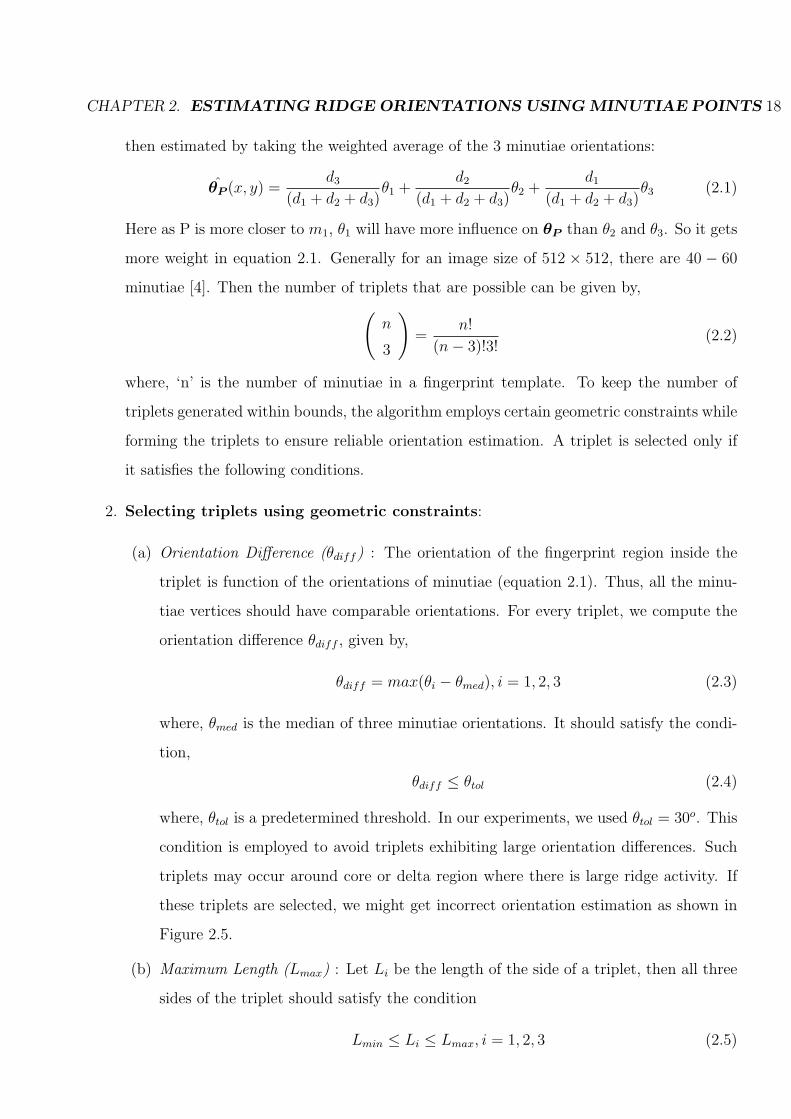
2. Selecting triplets using geometric constraints:
(a) Orientation Difference (θdiff) : The orientation of the fingerprint region inside the
triplet is function of the orientations of minutiae (equation 2.1). Thus, all the minu-
tiae vertices should have comparable orientations. For every triplet, we compute the
orientation difference θdiff , given by,
θdiff = max(θi − θmed), i = 1, 2, 3 (2.3)
where, θmed is the median of three minutiae orientations. It should satisfy the condi-
tion,
θdiff ≤ θtol (2.4)
where, θtol is a predetermined threshold. In our experiments, we used θtol = 30o. This
condition is employed to avoid triplets exhibiting large orientation differences. Such
triplets may occur around core or delta region where there is large ridge activity. If
these triplets are selected, we might get incorrect orientation estimation as shown in
Figure 2.5.
(b) Maximum Length (Lmax) : Let Li be the length of the side of a triplet, then all three
sides of the triplet should satisfy the condition
Lmin ≤ Li ≤ Lmax, i = 1, 2, 3 (2.5)

CHAPTER 2. ESTIMATING RIDGE ORIENTATIONS USING MINUTIAE POINTS 19
m 1
m 2
m 3
Figure 2.5: Example of a minutiae triplet with large θdiff .
where, Lmax is the maximum length that can be allowed for a triplet.
A triplet enclosing a large fingerprint area, might have regions exhibiting changes
in the ridge orientations. Thus, the orientation may not be estimated correctly for
underlying larger fingerprint region. Hence, the triplets enclosing large fingerprint area
need to be avoided. This is ensured by comparing the three side-lengths of minutiae
triplet against a threshold.
Deciding a single value for Lmax across all fingerprint classes is a difficult task. As
shown in Figure 2.6 (a), due to parallel ridge flow in Arch, larger side triplet can
also give reliable orientation estimation but in Whorls, due to the large ridge activity
near core region, this is not always true. In order to have a generic algorithm for
all fingerprint classes, this constraint is important. We used Lmax = 300 for our
experiments.
(c) Interior Angels (φmin) : Minutiae tend to occur in clusters [26]. In a cluster of
minutiae, there may be some triplets that enclose very small fingerprint area as shown
in Figure 2.6 (c). So using these triplets for estimating orientations is computationally
inefficient. To avoid these triplets, the interior angles and side-lengths of the triplet
are observed. A triplet is selected if,
φi > φmin, (2.6)
Li > Lmin, i = 1, 2, 3 (2.7)

CHAPTER 2. ESTIMATING RIDGE ORIENTATIONS USING MINUTIAE POINTS 20
where φi are interior angles of the triplet (Figure 2.6 (c)), φmin = 20o, and Lmin = 20
pixels. All three interior angles of a triplet should be greater than a preset threshold,
φmin, and also the minimum side-length should be greater than Lmin.
m 1
m 2
m 3
m 1
m 2
m 3 m 1
m 2 m 3
(a) (b) (c)
Figure 2.6: Example of a triplet with large Lmax for Arch and Whorl, (a) Correct result, (b)Incorrect result, (c) An example of skinny triple.
3. Pruning triplets using Quality Factor: As mentioned above, fingerprints are charac-
terized by clusters of minutiae in certain regions. For instance, the regions near the core and
delta have dense minutiae activity. In such cases, a triplet may reside inside the triangular
region of another triplet or may overlap with it. This results in multiple triplets enclosing
common fingerprint area. In Figure 2.7 (a) one triplet is completely included in another
(a) (b)
Figure 2.7: (a) Contained triplets, (b) Overlapping triplets.
whereas in Figure 2.7 (b) two triplets are overlapping. Here, rather than consolidating the
orientation information estimated by multiple triplets, we utilize the information estimated
only by a good quality triplet. To do so, a quality factor ‘Q’ is assigned to each triplet.

CHAPTER 2. ESTIMATING RIDGE ORIENTATIONS USING MINUTIAE POINTS 21
The quality, Q, is measured by examining the average length of the sides of the triangle
and the orientations of component minutiae points, and is computed as,
Q = (Lmax − Lavg)w1 + (θtol − θdiff
θdiff
Lmax)w2. (2.8)
Here, Lavg is the average length of the sides of the triplet, θdiff is the maximum difference
between pairwise minutiae orientations (equation 2.3), and w1, w2 are the weights associ-
ated with each term. We use w1 = 0.4 and w2 = 0.6. This ensures that a triplet having
minutiae of similar orientations and covering a relatively small area is assigned a higher Q
value. Thus in case of a tie, a triplet higher Q value is selected. Examples of the good and
bad quality triplets are shown in Figure 2.8.
(a) (b) (c)
Figure 2.8: (a) Minutiae distribution of a fingerprint, (b) Examples of good (blue), with Lavg= 112.66, Var = 5, Q = 237.63, and bad (red) with Lavg = 217, Var = 26, Q = 67.55, qualitytriplets, (c) Estimated orientation map.
4. Computing orientation map θ̂: Using equation 2.1, orientations of the ridge pixels
enclosed by valid triplets are estimated. An orientation map, θ̂, is a matrix where each cell
of this matrix represents the average orientation of a local window of the parent fingerprint
image. For example, in a 512×512 image, if we take a local window size of 13×13, then an
orientation map of size 39×39 is obtained by assigning the average orientation of the pixels
in the local window to the corresponding cell in the orientation map. Some cells may not
contain any orientation information due to the non-availability of ‘valid’ triplets in those
regions. The estimated orientation map for an Arch fingerprint is as shown in Figure 2.9.

CHAPTER 2. ESTIMATING RIDGE ORIENTATIONS USING MINUTIAE POINTS 22
(a) (b) (c)
Figure 2.9: (a) Original Arch, (b) Triplet formation, (c) Orientation Estimation Result.
5. Averaging orientation map: To obtain a smooth transition in orientations, the esti-
mated orientation map is convolved with a 3× 3 local averaging filter.
Some results for estimated orientation maps for other fingerprint classes are shown in Figure
2.10.
2.2 Validating the estimated orientation map
Visually, we observe that the estimated orientation map is quite consistent with the underlying
ridge flow of the original fingerprint. In order to verify the accuracy of the algorithm, we compare
the true orientation map with the estimated one using a correlation measure. The true orientation
map can be computed using various techniques as described in [4]. We use the least mean
square orientation estimation approach proposed by Ratha et al. [22] for computing the true
orientation maps of fingerprint images. Given a fingerprint image I, the algorithm computes the
ridge orientations at discrete points on the same cartesian grid used to compute θ̂.
1. Divide I into w × w blocks (e.g., 13 × 13); the center of each block corresponds to a grid
point.

CHAPTER 2. ESTIMATING RIDGE ORIENTATIONS USING MINUTIAE POINTS 23
(a) (b)
(c) (d)
(e) (f)
Figure 2.10: (a), (c) and (e) are original fingerprints of L, R and W whereas (b), (d) and (f) aretheir estimated orientation maps.

CHAPTER 2. ESTIMATING RIDGE ORIENTATIONS USING MINUTIAE POINTS 24
2. Compute Sobel gradients Gx and Gy at each pixel in a block and assign the average of
these gradient values to the corresponding grid point. The Sobel masks are given by,
Gx =
1 2 1
0 0 0
−1 −2 −1
, Gy =
−1 0 1
−2 0 2
−1 0 1
.
3. The orientation for a grid point is computed as,
θ(i, j) =1
2arctan(
Vy(i, j)
Vx(i, j)), (2.9)
where,
Vx(i, j) =i+w∑u=i
j+w∑v=j
2Gx(u, v)Gy(u, v), Vy(i, j) =i+w∑u=i
j+w∑v=j
G2x(u, v)−G2
y(u, v). (2.10)
The estimated and true orientation maps, (θ, θ̂), for different fingerprints in the NIST-4 database
are shown in Figure 2.11.
To determine the similarity between the true and estimated orientation maps, we compute
the correlation coefficient, r(θ, θ̂), given by, r(θ, θ̂) =∑
m
∑n(θ−θ̄)(θ̂−¯̂
θ)√(∑
m
∑n(θ−θ̄)2)(
∑m
∑n(θ̂−¯̂
θ)2), 0 ≤ |r| ≤
1, where, m × n is size of the orientation maps, θ̄ and¯̂θ represent the mean of θ and θ̂,
respectively. Figure 2.12 that plots the histogram of correlation coefficients as observed on the
NIST-4 database, validates our technique and indicates that the estimated ridge orientations are
consistent with the underlying (true) ridge flow. Due to the absence of ‘valid’ triplets around
the core region, the estimated orientation map can not capture these regions, e.g., the recurving
back in loops or the concentric pattern in whorls.
To improve the performance of fingerprint matching, the estimated orientation map may
also be used along with the minutiae distribution. The orientation estimation algorithm can be
beneficial in applications like smart cards (where memory is critical), since the orientation field
need not be stored explicitly but can be generated from the template itself.

CHAPTER 2. ESTIMATING RIDGE ORIENTATIONS USING MINUTIAE POINTS 25
(a) (b) (c)
Figure 2.11: Comparing the estimated orientation map (from minutiae) with the true map: (a)Minutiae plot of a fingerprint, (b) Estimated orientation map, (c) True orientation map. Due toabsence of valid triplets around the core region, the estimated orientation map cannot capturethese regions, e.g., the concentric pattern in whorls.

CHAPTER 2. ESTIMATING RIDGE ORIENTATIONS USING MINUTIAE POINTS 26
79% >0.75
Figure 2.12: Correlation between θ̂ and θ as observed on the NIST 4 database. About 79% ofthe orientation pairs have correlation more than 0.75.

27
Chapter 3
Fingerprint Classification Using
Minutiae Points
3.1 Fingerprint classification
The ridge flow in the fingerprints constitute a pattern which can be systematically categorized
into a fixed number of non-overlapping classes. Fingerprint classification refers to the problem
of assigning a fingerprint to a class in a consistent and reliable way [4]. This is an important
property of fingerprints since it helps in reducing the search time in identification schemes. The
Galton-Henry [2] classification scheme partitions fingerprints into five classes, namely, arch (A),
tented arch (T), right loop (R), left loop (L) and whorl (W) as shown in Figure 3.1. We treat this
as a four-class problem by combining fingerprints of T and A into a single class (A). The number
(a) Arch (b) Tented Arch (c) Whorl (d) Right Loop (e) Left Loop
Figure 3.1: Five classes of fingerprints according to Galton-Henry classification scheme [2]. Coreis represented by a square whereas the delta by a circle.
of singularities (core and delta points) and the relative positions vary across the 5 fingerprint
classes as summarized in table 3.1. Characteristics of each of these classes are described below:

CHAPTER 3. FINGERPRINT CLASSIFICATION USING MINUTIAE POINTS 28
Fingerprint class Number and position of singularitiesArch No singularities
Tented Arch One core and one delta, vertically alignedLeftloop One core and one delta, delta on right side
Rightloop One core and one delta, delta on left sideWhorl One core and two deltas, one delta on each side
Table 3.1: Number and position of singularities in five fingerprint classes.
1. Arch: This is the simplest fingerprint class since it does not have any singularities (core
or delta). Ridges enter from one side of the finger and exit from the other forming a shape
of an arch.
2. Tented Arch: These are similar to (plain) arch, except that it has at least one ridge which
has an up thrust. It has one core and one delta which are vertically aligned.
3. Whorl: The most complex form of fingerprints is the whorl pattern. It has one core, two
delta points, and a whorl-like pattern near the core. The whorl pattern is characterized by
at least one ridge traversing a 360 degree closed path around the core.
4. Left Loop: It is characterized by one core and one delta point. One or more ridges enter
from left of the finger and exit from the same side, thus forming a loop. It has a delta
where the ridges converge or diverge into two branches on the right side.
5. Right loop: Like left loop, it has one core and one delta. One or more ridges enter from
right side of the finger and exit from the same side by forming a loop. It has a delta on
the left side.
3.1.1 Need for fingerprint classification
Generally, the database of a fingerprint authentication system includes millions of fingerprints.
Large volumes of fingerprints are collected and stored every day in a wide range of applications,
including access control (e.g. ATM), law forensics (e.g. FBI database contains more than 200
million fingerprints [4]), driver’s license registration of state, etc.
For the identification, the simplest technique is to scan the entire database in order to retrieve
the top matches. This brute force method is obviously an inefficient and impractical way to

CHAPTER 3. FINGERPRINT CLASSIFICATION USING MINUTIAE POINTS 29
address the problem due to a very large response time. To alleviate this problem, fingerprints
are partitioned into predefined classes and are stored in separate bins in the database. At the
time of identification, the class of the query fingerprint is determined and it is compared against
the fingerprints of this class alone.
3.1.2 Various approaches for classification
Automated fingerprint classification is a difficult pattern recognition problem. In spite of
substantial research in this field, it is still an active field of research. A detailed discussion
about various methods proposed for fingerprint classification is available in [4]. Most existing
approaches use the following features along with the fingerprint image itself:
1. Orientation image : Most existing classification techniques make use of the orientation
image. If reliably computed, it is alone sufficient for classification. Cappelli and Maltoni
proposed a technique in which the orientation image is divided into homogeneous regions
using a cost function [27]. A prototype model is formed for each class using these regions.
A fingerprint is classified by comparing the relational graphs with the class prototypes.
This technique is rotation and translational invariant and does not involve singularities.
2. Singularities : In this technique, singularities such as core and delta are detected. The
fingerprints are classified based on the number and locations of these singularities [4].
Although it is relatively a simple technique, the performance is highly dependent on the
accuracy of core/delta detection. In case of noisy fingerprints, singularity detection is not
only difficult but can be misleading. Due to the small fingerprint area, dab prints generally
do not contain deltas.
3. Ridge flow : Ridge line flow is nothing but a set of curves running parallel to ridge lines.
These curves do not necessarily coincide with the fingerprint ridges and vallyes, but they
exhibit the same local orientation. It can be traced by drawing lines curves locally oriented
to the orientation image [28]. Jain and Minut [3] form predefined kernels corresponding to
each class using this ridge flow. A fingerprint is assigned a class based on fitting it to one
of these kernels. The best fitting kernel decides the class of the fingerprint.
4. Gabor filter responses : Jain et.al [29] proposed a classification algorithm using a bank
of Gabor filters. The algorithm separates the number of ridges present in four directions

CHAPTER 3. FINGERPRINT CLASSIFICATION USING MINUTIAE POINTS 30
(0o, 45o,90o,135o) by filtering the central part of a fingerprint with the bank of Gabor filters.
This information is quantized to generate a ‘FingerCode’ which is used for classification.
Some classification schemes proposed in literature use more than one feature. For example,
Candela et al. [28] developed PCASYS (Pattern-level Classification Automation SYStem). It is
a probabilistic neural network that is based on features derived from orientation image. It also
contains a ridge tracing module, which traces the ridge flow in the bottom part of the whorl type
fingerprint.
Various features that have been used so far for fingerprint classification are summarized in
Table 3.2.
Authors Features usedCandela et al. 1995 [28], Hong et al. 1999 [30], Chong et al. 1997 [31] Ridge line flowCappelli et al. 1999 [27], Senior 2001 [32], Wilson et al. [33] Orientation imageKaru and Jain 1996 [34], Cho et al. 2000 [35] SingularitiesJain et al. [29], Yao et al. 2001 [36] Gabor filtersRoss et al. [37] Minutiae points
Table 3.2: A summary of different fingerprint classification techniques.
3.2 Novel use of minutiae for classification
To best of our knowledge, none of the existing classification schemes use minutiae properties
for classification. Typically, minutiae points have been used only for fingerprint alignment and
matching. We propose a novel idea of using minutiae points alone for classifying fingerprints
(without accessing images).
It is observed in the forensic literature that the minutiae distribution varies from class to class
[38, 39, 8]. The minutiae plots of all four classes are shown in Figure 3.2. A visual glance at these
minutiae plots suggests the possibility of deducing the fingerprint class from the minutiae points.
Our hypothesis is based on observations made by forensic experts in the context of fingerprint
individuality models. Fingerprint minutiae have been the central focus in the study of fingerprint
individuality. Stoney describes 10 different individuality models proposed by various forensic
experts. All these models are based on minutiae properties [8]. Most of the individuality models
are based on heuristic observations and on a limited database. We have demonstrated the results
over larger fingerprint database.

CHAPTER 3. FINGERPRINT CLASSIFICATION USING MINUTIAE POINTS 31
(a) (b) (c) (d)
Figure 3.2: Minutiae plots of 4 fingerprint classes: (a) A, (b) W, (c) L, and (d) R.
As mentioned earlier, we assume that the stored minutiae template does not give information
about the shape of the fingerprint directly. We studied the relation between minutiae properties
and class of the fingerprints of NIST 4 database. Our observations and the findings listed
by various forensic experts support our hypothesis that the seemingly random distribution of
minutiae in a fingerprint can reveal important information about the class of a fingerprint.
Most forensic experts have invested their efforts in studying fingerprints visually. Our goal is
to imitate the performance of a human fingerprint expert for classification of fingerprint using
minutiae template without access to the fingerprint image itself.
Most commercially available fingerprint authentication systems store minutiae templates
which are later used for matching. We claim that with the proposed classifier, these templates
can be also used for fingerprint classification. This eliminates the need for existing complex image
processing techniques on fingerprint images for classification. We assume that the simplest form
of minutiae template (x, y, θ) is available and the information about the singularity points, class
etc is unknown. (The basic shape of the fingerprint is decided by location and orientation of
singularities. If the minutiae template were to store the position and orientation of singularities
then determining the class of fingerprint is a trivial task.)
3.2.1 Minutiae based classification algorithm
Predicting the class of a fingerprint from its minutiae points alone is not a easy task. This
is due to the fact that the fingerprint can be enrolled in any orientation or translation. So
the individual minutiae points can literally be in any position and orientation for the same
fingerprint. Thus, the features we have chosen for fingerprint classification are translation and

CHAPTER 3. FINGERPRINT CLASSIFICATION USING MINUTIAE POINTS 32
rotation invariant. The main steps of our minutiae-based classification algorithm are as described
in the block diagram shown in Figure 3.3. We have described the orientation estimation scheme
Forming minutiae triplets
Predicting orientation
map
Detecting ‘salient’
minutiae
Minutiae template
Forming feature vector
K-nearest neighbor classifier
class
Figure 3.3: Block diagram showing main steps of minutiae-based classification algorithm.
using minutiae triplets in Chapter 2.
1. Detecting salient minutiae : As mentioned above, the designed classifier is based on
minutiae information and the estimated orientation of the fingerprint to be classified. A
fingerprint can be divided into 3 parts namely base, core and marginal areas. By visually
analyzing fingerprint ridge patterns across classes, it is clear that they have almost the same
ridge structure in the base and marginal area as shown in Figure 3.4. But the irregularities
in the vicinity of the core area are significant for classification, such as a circular ridge
pattern in case of whorls or curving back of ridges in loops. Accordingly, the minutiae
Marginal Area
Core Area
Base Area
(a) (b)
(c) (d)
Figure 3.4: (a) and (b) show L and W fingerprints divided into various areas whereas (c) and(d) show the corresponding original fingerprints respectively.
present in the vicinity of the core point have important class representative characteristics.
We refer to these as ‘salient’ minutiae and use them for classification. The ridges around

CHAPTER 3. FINGERPRINT CLASSIFICATION USING MINUTIAE POINTS 33
the core point have high curvature and form a nearly circular pattern across all classes as
shown in Figure 3.2. In order to select the salient minutiae, we first detect a registration
point (R0) using Hough transform (The salient minutiae reside around R0). Our motivation
behind using Hough transform is the inherent circular-like ridge structure of fingerprints
in the vicinity of core region.
The Hough transform is a technique which can be used to isolate features of a particular
shape within an image. The classical Hough transform is most commonly used for the
detection of regular curves such as lines, circles, ellipses, etc [40]. It is particularly useful
for computing a global description given the local (noisy) measurements. In our case, the
local information consists of minutiae coordinates and their orientations. The parametric
equation of a circle is
(x− x0)2 + (y − y0)
2 = r2, (3.1)
where ‘x0’ and ‘y0’ are the coordinates of the center of the circle and ‘r’ is the radius. The
parameter space consists of three coordinates viz. the position of minutiae point (x, y) and
its orientation θ.
As mentioned above, the orientation of minutiae in the vicinity of the core region define
a circle. Consider a circle formed by minutiae as shown in Figure 3.5. Let ‘L’ be a
perpendicular line to a minutiae orientation. This line passes through the center of the
circle. Our goal here is to detect the center. It can be observed that these minutiae have
r
L
(x, y) R 0
r
L
m
(x, y) R 0 (x, y) R 0
L
m (x, y)
R o
(x, y)
R o
(x, y) (x, y)
R o
L L
30 o
(a) (b) (c)
Figure 3.5: (a) Circular plot of minutiae, (b) Line ‘L’ is perpendicular to the orientation ofminutiae m, (c) L made nearly perpendicular (± 30o) to the orientation θ.
orientations almost tangential to the circumference of the circle. Using this property, for

CHAPTER 3. FINGERPRINT CLASSIFICATION USING MINUTIAE POINTS 34
each minutiae ‘m’ we traverse its line ‘L’ perpendicular to the orientation of minutiae θ
at discrete points as illustrated in Figure 3.5 (b). These points (x, y) correspond to the
probable center points of the circle. The radius ‘r’ of each of these circles is nothing but
distance from minutiae to the corresponding center points as the minutiae ‘m’ lies on their
circumferences. A 3D accumulator in Hough space corresponding to the center (x, y) and
radius r is used. Given a minutiae template M = mi, i = 1 to N , the algorithm for detecting
the R0 is as follows.
(a) Initialize the accumulator A(x, y, r) where (x, y) is the center of the potential circle
with radius r.
(b) For each minutiae mi, i = 1 to N , the potential centers (x, y) lie on the line ‘L’.
The accumulator cell A(x, y, r) is incremented if the point (x, y) is at distance r from
minutiae mi.
(c) For a circular minutiae pattern, there will be a well-pronounced peak in the Hough
parameter space for one center (x, y) (point marked with red ‘*’ in Figure 3.5 (a)). This
corresponds to the registration point which is characterized by significant minutiae
activity around it.
We observed that rather than using only the minutiae information, if we use the estimated
orientation map then the performance of Hough transform is improved. As mentioned
earlier, orientation map is a discrete matrix. Each cell of the orientation map represents
the average estimated orientation for that cell. We perform above procedure for all the
starting coordinates of the non-empty cells of the orientation map. Note that the ridge
structure in fingerprints is not exactly circular thus in our experiments, we use lines nearly
perpendicular (± 30o) to the orientation θ as shown in Figure 3.5 (c). The results for Hough
transform using the estimated orientation maps are as shown in Figure 3.6. Note that R0 is
mostly detected in the vicinity of the true core. Once R0 is detected, the minutiae located
in a 300× 300 region about R0, are selected for classification as shown in Figure 3.7.
2. Generating feature vectors : Each fingerprint is represented by a feature vector, set of
characteristic measurements extracted from salient minutiae. These features capture vital
properties of minutiae such as their relation with neighboring minutiae, relation between

CHAPTER 3. FINGERPRINT CLASSIFICATION USING MINUTIAE POINTS 35
(a) (b)
(c) (d)
(e) (f)
Figure 3.6: Minutiae plot overlaid on original fingerprint of A, L and W are shown in (a), (c)and (e) respectively. The corresponding R0 points marked in blue (‘X’) detected using estimatedorientation maps are shown in (b), (d) and (f).

CHAPTER 3. FINGERPRINT CLASSIFICATION USING MINUTIAE POINTS 36
(a) (b)
Figure 3.7: (a) The orientation map and detected registration point marked in blue (‘*’), (b)Salient minutiae in a 300× 300 frame about R0.
their coordinates and orientations, their clustering tendencies, etc. Most of these class-
representative minutiae properties were studied by various forensic experts for proposing
individuality models and for understanding the unique nature of fingerprints but not for
classifying the fingerprints [39, 8, 38, 26]. The features we have used are invariant to
rotation, translation and scaling of fingerprint images. The 11-dimensional vector F =
{F1, F2, · · · , F11} is constructed as follows.
(a) Features based on minutiae orientations (F1, F2) : Stoney claims that minutiae
orientations are robust to fingerprint distortions. The direction of ridge flow varies
from one class to other and so do minutiae orientations. For instance, W has at least
one ridge which makes 360 degree closed path in the central region of the fingerprint.
Thus the orientations of these minutiae range from 0− 360 degrees. On the contrary,
the minutiae orientations of A have only two dominant directions. Roxburgh [38] ob-
served correlation between minutiae orientations and class of the fingerprint. In order
to understand the distribution of minutiae orientations for each class, we examined the
rose plots 1 of minutiae orientations (Figure 3.8). It can be noted that the rose plots
for whorl and arches are different. Whorl is characterized by high minutiae density
around the core region. Also due to the circular pattern, the minutiae orientations are
in various directions. So the rose plot for W is distributed in all four quadrants of the
1 The rose plot is a a polar plot showing the histogram of angles.

CHAPTER 3. FINGERPRINT CLASSIFICATION USING MINUTIAE POINTS 37
rose plot. Arches have comparatively less number of minutiae. Also their orientations
fall in fixed quadrants, hence the rose plot has two dominant peaks. The rose plots
for L and R are mirror images of each other. One feature capturing these variations
in minutiae orientations across classes is the number of empty bins in the rose plot
(F1). This indirectly captures the spread of minutiae orientations. The feature F2 is
the variance in minutiae orientations of a minutiae template.
2
4
6
8
30
210
60
240
90
270
120
300
150
330
180 0
1
2
3
4
30
210
60
240
90
270
120
300
150
330
180 0
2
4
6
8
30
210
60
240
90
270
120
300
150
330
180 0
2
4
6
30
210
60
240
90
270
120
300
150
330
180 0
(a) (b) (c) (d)
Figure 3.8: Rose plots of (a) A, (b) W, (c) L, (d) R.
(b) Features relating minutiae pairs (F3,· · · ,F6) : The fingerprint individuality model
proposed by Stoney and Thornton uses minutiae pairs [8]. They suggest that minutiae
pairs are a fundamental unit for representing variations in fingerprints . They also
found a strong correlation between the spacing and orientations of minutiae pairs. Also
Roxburgh [38] considered correlation between neighboring minutiae and variation in
minutiae position relative to the pattern of fingerprint for proposing his individuality
model. The properties of minutiae in a local neighborhood vary across classes. For
instance, the neighboring minutiae in the central region of W have large orientation
difference where as minutiae neighbors in A have similar orientations. The corre-
lation between spatial location and orientations of minutiae pairs can be examined
by estimating the joint distribution of ‘R’ and ‘Φ’ where R is the distance between
two minutiae and Φ is the orientation difference as shown in equations (3.2) to (3.5).
The first distribution corresponds to minutiae pairs which are spatially close to each
other and having almost similar orientations, and second to the pairs which are close
but having large orientation difference. Similarly, the third joint distribution includes
minutiae pairs away from each other and having similar orientations whereas fourth
includes pairs away from each other but having large orientation differences. Figure

CHAPTER 3. FINGERPRINT CLASSIFICATION USING MINUTIAE POINTS 38
3.9 shows all the four types of minutiae pairs.
F3 =∑
0≤R≤R1
∑0≤Φ≤Φ1
P (R, Φ) dR dΦ, (3.2)
F4 =∑
0≤R≤R1
∑Φ1≤Φ≤Φ2
P (R, Φ) dR dΦ, (3.3)
F5 =∑
R≥R2
∑0≤Φ≤Φ1
P (R, Φ) dR dΦ, (3.4)
F6 =∑
R≥R2
∑Φ1≤Φ≤Φ2
P (R, Φ) dR dΦ, (3.5)
In our experiments, we have taken R1 = 60 pixels, R2 = 180 pixels, Φ1 = 30o and
Φ2 = 180o. It is observed that these distributions are significantly different for all
4 classes. The above probabilities can be computed by finding the number of pairs
satisfying the above mentioned criteria for R and Φ divided by the total number of
minutiae pairs formed in a template. For A, F3 is larger among four features whereas
for whorls, F4 3.9 We observed that for loops, the values for F1, F3 are larger.
F 6
F 5
F 5
F 4 F 3 F 6
Figure 3.9: A whorl minutiae plot showing 4 types of minutiae pairs.
(c) Features representing clustering of minutiae (F7, F8) : It is observed that minu-
tiae tend to cluster. Kingston [26] estimated probability of a particular number

CHAPTER 3. FINGERPRINT CLASSIFICATION USING MINUTIAE POINTS 39
of minutiae from the minutiae density assuming Poisson distribution. He observed
variations in minutiae density among different-sized regions across different locations
within the fingerprint (minutiae density increases near core and delta regions). Stoney,
Champod and Margot observed that there are variations in minutiae densities due to
different patterns of the ridge flow, for example, in the region of recurving ridges [8].
If an equal number of ridges flow in and out of a region, then for each minutia that
produces a ridge, there must be a minutia which consumes a ridge. An imbalance
in number of minutiae orientations results in converging or diverging ridges. There
exists a fundamental relationship between minutiae and ridge pattern. Also Galton
[39] showed that there is a strong correlation between the class of a fingerprint and
the occurrence of a minutiae at a specific location in the image (Figure 3.10). Whorls
are characterized by high minutiae density near the core region. The clusters of minu-
tiae are obtained in various regions of fingerprint. Champod and Margot observed
that these regions vary from class to class [41]. F7 is the maximum minutiae density
obtained in each fingerprint. This value is relatively maximum for W and least for A.
We sample the local minutiae in a radius of 50 pixels to compute the minutiae density.
The feature F8 is the maximum variance in minutiae orientations in a minutiae cluster
within this radius.
5 10 15 20 25 30
5
10
15
20
25
305 10 15 20 25 30
5
10
15
20
25
305 10 15 20 25 30
5
10
15
20
25
305 10 15 20 25 30
5
10
15
20
25
30
(a) (b) (c) (d)
Figure 3.10: Minutiae density associated with 4 different classes of fingerprints: (a) A, (b) W,(c) L, and (d) R. These plots were generated using 30 images per class. Blue indicates a lowdensity region while red indicates a high density region.
(d) Features capturing global ridge information (F9, F10, F11) : Visually (Figure
2.2) it is apparent that features F1 · · ·F8 can distinguish classes A and W but are
not sufficient for reliably resolving ambiguity between the classes (L, R), (A, L, R)
and (L, R, W). It is necessary to include information about global ridge pattern

CHAPTER 3. FINGERPRINT CLASSIFICATION USING MINUTIAE POINTS 40
along with the local minutiae properties. To capture the global ridge structure of the
fingerprint, we have defined geometric kernels which model the shape of the fingerprint
around the core region for W, Land R classes. In a left loop, the ridges in the core
region form a loop by curving back to the left side of the fingerprint. This is captured
by a kernel formed using two semi-ellipses corresponding to the concave and convex
parts of the loop. The kernel for R is nothing but a mirror image of this kernel. The
circular ridge structure of W is represented using a simple circle. See Figure 3.11.
(a) (b) (c)
Figure 3.11: Kernel for (a) L, (b) R, and (c) W.
Above the core region of every fingerprint has arch-like characteristics (Figure 3.4). We do
not define a kernel for A class as it would fit well for all the classes. The algorithm we have
used is based on hierarchical kernel fitting approach proposed by Jain and Minut [3] for
fingerprint classification with certain modifications to suit our problem. It is a model-based
approach which uses only flow field of ridges for fingerprint classification. In this approach,
the classification is achieved by finding the kernel that best fits to the flow field of a given
fingerprint. The algorithm is presented in this paper is as follows. Consider V to be a
smooth vector field defined over some region in the plane R2 and let β be its argument.
Let γ be a circular kernel curve in R2 as shown in Figure 3.12. Let γ̇ be tangent to γ and
α be its argument. Consider a point γt = (x(t), y(t)) present on the kernel γ. An energy
functional capturing the difference between the direction of γ̇ and that of the vector field
V at point γt is defined by
E(γ) =
∫γsin2(α− β(γ)) dγ∫
γdγ
(3.6)

CHAPTER 3. FINGERPRINT CLASSIFICATION USING MINUTIAE POINTS 41
Figure 3.12: Red Vector: Unit tangent vector to the kernel, Green Vector: Direction of flowfield at point γt [3].
To find how well each kernel fits into an orientation map of the fingerprint, energy values
(Equation 3.6) for various discrete points on the kernel are computed. Then the average of
all the value decides the fit. Lesser average means better fitting kernel. The classification
then becomes a simple energy minimization problem. This algorithm uses the original
fingerprint image for finding the orientation map. In our case, we have only the partial
orientation map estimated from minutiae. We use the kernel fitting approach for finding
features which represent the global ridge pattern of the fingerprint. For each estimated
orientation map, we find three values for energy functionals (Equation 3.6) corresponding
to the L, R, and W kernels which form the features (F9, F10, F11) respectively. The least
value represents the best fitted kernel. So for an orientation map of W, it is expected that
the minimum of three features is F11 where as for L and R, F9 and F10 respectively. We
observed that due to the inherent similarity in ridge structure of loops and A, both L and
R kernels fit well for A. So for A class values for F9 and F10 are almost the same. This
property is useful for resolving ambiguity between loops and A. These class-specific kernels
are defined with respect to the R0 obtained using Hough transform i.e. for W, R0 is the
center of the circle whereas for L and R, a focus of the ellipse kernel.
The rotation and translation of fingerprints are taken into account by subjecting these
kernels for following transformations. In our experiments, for W, we vary the radius of
the kernel from 100 to 160 pixels. The various shapes of ellipse for L and R classes are
obtained by varying the semi-major axis from 120 to 180 and semi-minor axis from 60
to 100 pixels. The angle that ellipse makes with the horizontal is varied from −10 to
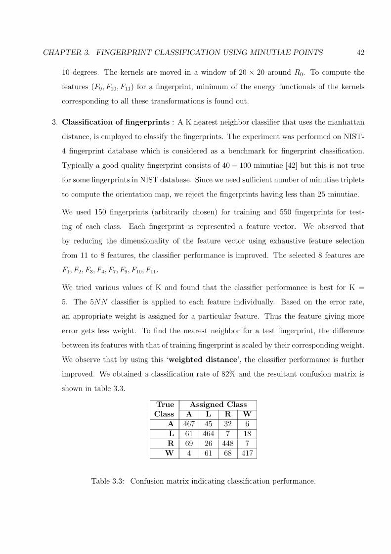
CHAPTER 3. FINGERPRINT CLASSIFICATION USING MINUTIAE POINTS 42
10 degrees. The kernels are moved in a window of 20 × 20 around R0. To compute the
features (F9, F10, F11) for a fingerprint, minimum of the energy functionals of the kernels
corresponding to all these transformations is found out.
3. Classification of fingerprints : A K nearest neighbor classifier that uses the manhattan
distance, is employed to classify the fingerprints. The experiment was performed on NIST-
4 fingerprint database which is considered as a benchmark for fingerprint classification.
Typically a good quality fingerprint consists of 40− 100 minutiae [42] but this is not true
for some fingerprints in NIST database. Since we need sufficient number of minutiae triplets
to compute the orientation map, we reject the fingerprints having less than 25 minutiae.
We used 150 fingerprints (arbitrarily chosen) for training and 550 fingerprints for test-
ing of each class. Each fingerprint is represented a feature vector. We observed that
by reducing the dimensionality of the feature vector using exhaustive feature selection
from 11 to 8 features, the classifier performance is improved. The selected 8 features are
F1, F2, F3, F4, F7, F9, F10, F11.
We tried various values of K and found that the classifier performance is best for K =
5. The 5NN classifier is applied to each feature individually. Based on the error rate,
an appropriate weight is assigned for a particular feature. Thus the feature giving more
error gets less weight. To find the nearest neighbor for a test fingerprint, the difference
between its features with that of training fingerprint is scaled by their corresponding weight.
We observe that by using this ‘weighted distance’, the classifier performance is further
improved. We obtained a classification rate of 82% and the resultant confusion matrix is
shown in table 3.3.
True Assigned ClassClass A L R W
A 467 45 32 6L 61 464 7 18R 69 26 448 7W 4 61 68 417
Table 3.3: Confusion matrix indicating classification performance.

CHAPTER 3. FINGERPRINT CLASSIFICATION USING MINUTIAE POINTS 43
(a) (b) (c) (d)
Figure 3.13: Small inter-class variability between classes L and T (a) R and W, (b) and largeintra-class variability between two prints of whorl class (c) and (d).
Unlike other classification schemes, our classifier does not require any other image processing
techniques other than minutiae extraction.
3.3 Analyzing classifier performance
Above classification performance gives evidence for an indispensable relation between the class
of the fingerprint and minutiae distribution. This adds an additional insight to individuality of
fingerprints and may alleviate the public concern about the scientific basis for individuality of
fingerprints. Use of minutiae for fingerprint classification can be considered as an example of
super resolution where from bare minimum information about minutiae, we are interpolating
global information of the fingerprint image. Though our classification result is inferior to the
present state-of-the-art classification techniques [4], our intention is to show that it is feasible
to assign a class to the fingerprint using its minutiae template alone. Mostly all the fingerprint
databases are characterized by noisy fingerprints introduced at the time of acquisition. Some
partial fingerprints may be lacking important global features. Fingerprints are non-uniformly
distributed. The natural distribution of fingerprints into 5 classes is highly skewed - arch (3.7%),
tented arch (2.9%), left loop (%33.8), right loop (31.7%), and whorl (27.9%) [33]. Definition of
each fingerprint class is both vague and complex. Even human experts having good experience
cannot classify some ambiguous fingerprints. (About 17% of 4000 images in NIST database 4
have 2 different ground truth tables.) The NIST 4 dataset has quite a few low quality and
partial fingerprints (not capturing delta) Fingerprints have large intra-class variability i.e. prints
of same class may have entirely different characteristics and small intra-class variability i.e. prints
of different classes look similar as shown in Figure 3.13.
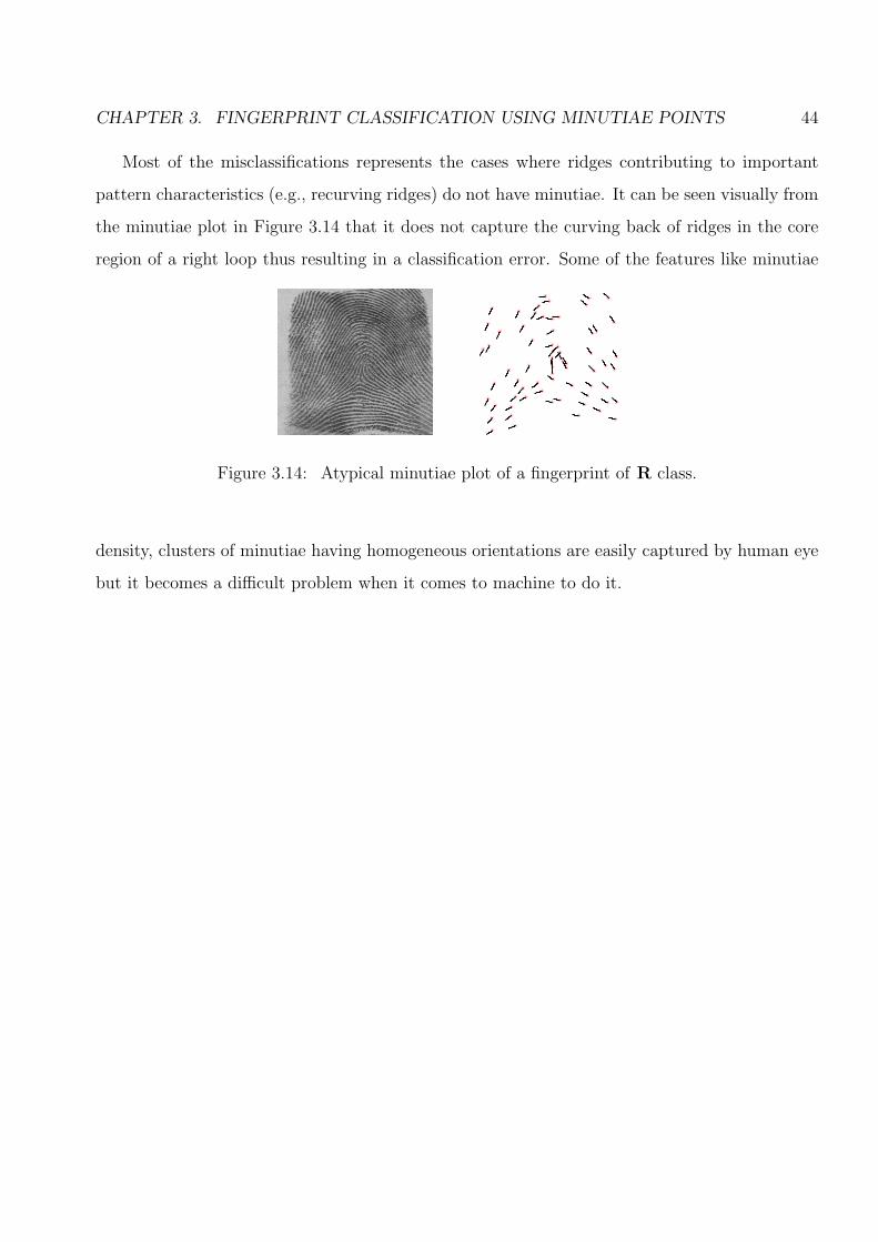
CHAPTER 3. FINGERPRINT CLASSIFICATION USING MINUTIAE POINTS 44
Most of the misclassifications represents the cases where ridges contributing to important
pattern characteristics (e.g., recurving ridges) do not have minutiae. It can be seen visually from
the minutiae plot in Figure 3.14 that it does not capture the curving back of ridges in the core
region of a right loop thus resulting in a classification error. Some of the features like minutiae
Figure 3.14: Atypical minutiae plot of a fingerprint of R class.
density, clusters of minutiae having homogeneous orientations are easily captured by human eye
but it becomes a difficult problem when it comes to machine to do it.
45
Chapter 4
Reconstruction of fingerprints
A minutiae template is a compact version of the original fingerprint image. Thus, tradition-
ally, it has always been considered to be secure to store it in the database. In earlier chapters
(Chapters 2, 3), we demonstrated that the minutiae template reveals significant amount of in-
formation such as ridge orientations and class of the parent fingerprint. In this chapter, we
investigate the possibility of reconstructing fingerprints from minutiae. By the term ‘reconstruc-
tion’ of fingerprints, we mean, to regenerate fingerprint from its stored minutiae points. The
reconstructed fingerprints can be used to spoof the authentication system and thus can be used
for fraudulent purposes. This can be referred as masquerade attack on fingerprints. As described
earlier (Chapter 1), Adler [14] has shown that, given access to the match score data, it is pos-
sible to reconstruct the enrolled face image using the face recognition template. Also, Hill [15]
demonstrated that fingerprint like artefact can be generated from its stored minutiae points.
To the best of our knowledge, a technique for reconstructing fingerprint with minutiae points
at desired locations has not been proposed in the literature. But, various approaches have
been proposed for generating synthetic fingerprints. We first review the literature pertaining to
synthetic fingerprint generation before discussing our scheme.
4.1 Synthetic fingerprint generation
Due to extensive use of fingerprint based authentication systems in commercial and civilian
world, significant efforts are being made to design efficient fingerprint recognition algorithms.
Usually these algorithms are evaluated on small proprietary databases. It is crucial to analyze
and evaluate the matching performance of these algorithms on a larger database. Collecting large

CHAPTER 4. RECONSTRUCTION OF FINGERPRINTS 46
number of fingerprint images is expensive, tedious and time consuming. Also, it involves privacy
issues as people may not be comfortable sharing their personal biometric data. These problems
are alleviated by utilizing synthetic fingerprint generation software. A synthetic fingerprint is
the ridge pattern that exhibits all the characteristics such as uniqueness and permanence as that
of a real fingerprint. Two such commercially available synthetic fingerprint generation softwares
are SFINGE [43] and Optel’s Fingerprint Creator [44].
A detailed discussion of various approaches for synthetic fingerprint generation can be found
in [4]. Three of them are discussed below.
1. Fourier Spectrum: Novikov and Glushchenko [45] proposed a ridge generation technique
that operates in frequency domain. Firstly, an orientation image is artificially generated.
The output image is initialized to a random image. For every pixel (x, y) in the random
image, a 2D Fourier spectrum of local window centered around (x, y) is taken. Then,
from the Fourier spectrum, the highest-energy along the normal to the local ridge direction
at (x, y) (obtained from orientation image) is selected. The highest-energy harmonic in
frequency domain corresponds to a 2D sinusoid in spatial domain. All such sinusoids are
summed and the result is binarized. This procedure is repeated iteratively till a smooth
image is obtained.
2. Fingerprint Creator : A Poland company named ‘Optel’ [44] has developed a software
to generate synthetic fingerprints using a mathematical model based on minutiae and class
information of the ridge pattern. Being a commercial software, no information about their
fingerprint generation algorithm is currently available. The software takes various inputs
such as class type, number of minutiae, density, rotation, translation in x and y direction,
etc, but it does not take positions of minutiae points as input. Thus this method cannot
be used to generate fingerprints having predefined minutiae locations.
3. SFINGE : This is a commercially available software developed by Cappelli et al. [43]. It
consists of a model which characterizes the acquisition of fingerprint through an online-
sensor. Authors claim that, with few changes in the algorithm, fingerprint impressions
using ‘ink-technique’ can also be generated. Their algorithm has 2 main steps. In the first
step, a master fingerprint is generated and in the second step, multiple impressions of the
same fingerprint are generated. Given certain input parameters such as fingerprint class,

CHAPTER 4. RECONSTRUCTION OF FINGERPRINTS 47
numbers and positions of singularities, ‘seed points’, etc., the algorithm can generate large
fingerprint databases.
• Generation of Master Fingerprint : A master fingerprint is a ridge pattern that
exhibits properties like uniqueness and permanence of a “synthetic finger” [4]. The
generation of a master fingerprint is carried out in 4 steps:
(a) Fingerprint Shape Generation : Authors visually examined shapes of a large
number of fingerprint images and prepared a simple model, based on four elliptical
arcs and a rectangle. Depending upon the shape and size of the finger, the shape
of a fingerprint is generally elliptical or circular. By changing a few parameters
like the lengths of the minor and major axes of the ellipses, most of the shapes
present in the real fingerprint images can be generated using this model.
(b) Orientation Image Generation : The orientation image generation is based on
the technique proposed by Sherlock and Monro [20]. It requires the number and
positions of core and delta points as input. In this model, the orientation image
is represented in a complex plane, i.e., each location of the orientation image is
considered as a complex number. Consider poles and zeros of the complex plane
to be the coordinates where cores and deltas are located. Let Ci, i = 1, 2, ..nc and
Di, i = 1, 2, ..nd be the coordinates of cores and deltas respectively. Consider a
point z = [x, y], then its orientation θ is obtained by,
θ =1
2[
nd∑i=1
arg(z − Ci)−nc∑i=1
arg(z −Di)], (4.1)
where, the function arg(x) yields the phase angle of the complex number x. To
generate an orientation image, first a fingerprint class is randomly chosen and
accordingly, the singularity points are randomly selected. Due to absence of
singularities in A class, this method cannot be used to generate arches. Instead,
a simple sinusoidal function is used to generate an arch.
It was observed that this orientation model cannot determine the ridge flow ac-
curately and, hence, SFINGE uses a variant of Sherlock and Monro’s orientation
model proposed by Vizcaya and Gerhardt [46] to provide more variations to the
orientation image. This increases the number of degrees of freedom to cope with
the variability in orientations.

CHAPTER 4. RECONSTRUCTION OF FINGERPRINTS 48
(c) Frequency image generation : This image decides the ridge frequency (density)
in the generated fingerprint. Cappelli et al. observed a large number of real fin-
gerprints to decide the overall ridge frequency. The overall frequency is chosen
according to the distribution of ridge line frequency in real fingerprints. An av-
erage inter ridge distance of 9 pixels is selected (according to a 500 dpi sensor
[4]). Authors observed that the regions above the northernmost loop and below
southernmost delta have lower ridge line frequency than other regions in finger-
print. Thus the frequency is decreased in these regions. The frequency image is
then randomly perturbed. Next, an averaging filter of a 3 × 3 size is used for
smoothing the frequency image.
(d) Ridge Pattern Generation : SFINGE uses a very simple but powerful algorithm for
generating ridge patterns. It uses space variant Gabor-like filters that are tuned
to local ridge orientations and the frequency image. A white image is initialized
with few random seeds. Then the Gabor filters are iteratively applied this white
image, resulting in ridge-like patterns. Different types of fingerprint minutiae
such as ridge endings, bifurcations, islands, etc. are generated automatically at
random positions. The authors claim that the minutiae are generated from the
ridge line disparity produced by local convergence/divergence of the orientation
field and by frequency changes. Gabor filters have been used as an effective tool
for fingerprint enhancement [47] and fingerprint matching [29]. But the authors
successfully used these filters for fingerprint generation.
• Generation of Synthetic Fingerprint Impressions from Master Fingerprint:
Realistically, different impressions of the same finger captured by the same sensor,
look significantly different. This is due to various factors like translation, rotation,
non-linear distortion produced due to pressure, random noise, cuts, and bruises, etc.
To synthetically generate various impressions of the same master fingerprint, following
factors are varied:
(a) Variation in ridge thickness : The thickness of the ridge varies across various
areas of the same fingerprint. It depends on the skin dampness and pressure
applied when finger is put on a scanner. When the skin is wet or pressure is high,
ridges appear thicker whereas when skin is dry and pressure is low, it appears

CHAPTER 4. RECONSTRUCTION OF FINGERPRINTS 49
thinner. The morphological operators such as dilation and erosion, are be applied
for changing the thickness of the fingerprint ridges. The erosion operator aids in
simulating low pressure or dry skin whereas the dilation operator in high pressure
or wet skin. The size of the structuring element is varied to modulate the thickness
of the ridge.
(b) Introducing non-linear distortion : The fingerprints are characterized by non-
linear distortions due to the pressure applied by the finger on the sensor surface
during acquisition. Authors use a skin-distortion model to simulate this non-linear
distortion in the generated fingerprint [48]. This model was originally proposed to
re-map the minutiae points to cope with the non-linear distortion for improving
the performance of fingerprint. In SFINGE, this model is applied to the whole
image in order to simulate distorted impressions. Lagrangian interpolation is used
to obtain smoothed gray-scale deformed images.
(c) Translation/Rotation : During fingerprint acquisition, the fingerprint image may
not be centrally aligned. It might be translated and/or rotated. SFINGE gener-
ates various impressions by rotating and translating the master fingerprint.
(d) Addition of Noise : The non-uniform pressure of the finger against the sensor,
the presence of small pores in the ridges, etc. make the fingerprint image noisy
during acquisition. To introduce noise in the master fingerprint, small white blobs
of various sizes and shapes are added.
(e) Background : SFINGE can generate backgrounds similar to that of the impres-
sions captured by capacitive and optical sensors. A statistical model based on
KL transform [49] is used for background generation. It requires a training set of
certain background-only images. SFINGE uses Eigen value analysis for the back-
ground generation. Each background image is represented as a column vector. A
mean vector of these images is computed. Then the mean vector is subtracted
from each background image vector and a covariance matrix of all these vec-
tors is computed. Using the significant eigen values, new background images are
generated.
The process of fingerprint generation using SFINGE software is shown in Figure 4.1.

CHAPTER 4. RECONSTRUCTION OF FINGERPRINTS 50
(a) (b) (c)
(d) (e) (f)
Figure 4.1: The process used by SFINGE to generate fingerprints: (a) Fingerprint shape gen-eration, (b) Orientation image for a given set of core and delta points, (c) Output white imageinitialized with random seeds, (d) Generation of ridge pattern and minutiae initiated from seedpoints, (e) Synthetic L fingerprint, (f) Synthetic fingerprint with noise. (All figures are generatedusing SFINGE software).

CHAPTER 4. RECONSTRUCTION OF FINGERPRINTS 51
The fingerprint images generated by SFINGE appear very realistic. These fingerprint images
were used to make a database namely DB4, for Fingerprint Verification Competitions (FVC2000
and FVC2002). In this competition, three other databases (DB1, DB2, and DB3) were obtained
from real fingers. The performance of fingerprint matching algorithms on all four databases was
observed and analyzed. The matching algorithms exhibit similar performance on DB4 as on the
real fingerprint databases. This suggests that the fingerprints generated by SFINGE are realistic
from the point of view of matching.
4.2 Reconstructing fingerprints from minutiae points
We assume that the stored template contains minimum information about the minutiae, i.e.,
their positions and orientations. The stored minutiae points give no direct information about the
overall shape of the fingerprint, the width of the ridges, the inter-ridge distance, etc. Fingerprints
are characterized by complex ridge patterns. Thus, given a minutiae template, a deterministic
generation of fingerprint ridge pattern is certainly not an easy task. During the enrolment
process, the information about the original fingerprint can be lost due to the following factors:.
1. Generally to extract the minutiae points, various pre-processing techniques like image edge
detection, binarization, thinning, etc. are employed. This may lead to significant loss of
fingerprint information.
2. Also, most commercial softwares for minutiae extraction employ techniques to remove
spurious minutiae. This may also result in the removal of some genuine minutiae. So the
minutiae template might not contain all the significant minutiae
3. During acquisition of a fingerprint, due to improper finger placement, all the minutiae
points may not be captured. Thus the stored minutiae template may not correspond to
the entire fingerprint area.
Thus, it is is not feasible to recreate the original fingerprint image entirely using only the stored
minutiae points. However, the template stores all the information required by the software for
fingerprint matching. Therefore, if a digital artefact is recreated from the template, it can be
used to spoof an authentication system.

CHAPTER 4. RECONSTRUCTION OF FINGERPRINTS 52
Given a minutiae template, we first estimate the orientation map from the minutiae distri-
bution. We next proceed to generate the ridge structure of the parent fingerprint. We propose
two schemes for fingerprint reconstruction. The first scheme uses space-variant Gabor-like filters
based on SFINGE [43]. Although it generates ridge like patterns, it does not have control over
the number and position of minutiae points in the reconstructed fingerprint. The second scheme
uses streamlines and LIC (Line Integral Convolution). It enables us to generate minutiae at
desired locations. The reconstructed fingerprint-like artefact has the appearance of the original
fingerprint.
4.2.1 Reconstructing fingerprints using Gabor-like filters
We use the Gabor-like filter as used in [43] for reconstructing fingerprints. SFINGE uses class
information and positions of cores and deltas to generate an orientation map using Sherlock and
Monro’s model [20]. Unlike SFINGE, we have information about minutiae positions and their
orientations only. We use the estimated orientation map θ̂ obtained using minutiae triplets.
Each cell of this discrete map contains the average estimated orientation of a 13 × 13 local
window of the parent fingerprint image. Note that, as this is a partial orientation map, some of
its cells might not have any orientations. For each non-empty cell of θ̂, ridges in the direction
represented by the cell, are generated using a Gabor-like filter. The Gabor-like filter is tuned to
the orientation contained by each cell. The filter is obtained by taking the product of a Gaussian
by a cosine plane wave. A correction term is included to remove the DC component. The filter
is given by,
f(v) =1
σ2e−
||v||22σ2 [cos(K.v)− e−
σ||K||22 ] (4.2)
where, σ2 is the variance of Gaussian which decides bandwidth of the filter, K = [kx, ky], is the
wave factor of the plane wave. Here ‘v’ is the location (x, y) in the output image where the filter
is to be applied. The parameters σ and K are adjusted using local ridge orientation and density.
Let O(v) be the orientation of the pixel at location (x, y). The parameter ‘D’ decides the ridge
density in the generated fingerprint. The vector K is then found by the solution of following two
equations.
D =√
k2x + k2
y (4.3)

CHAPTER 4. RECONSTRUCTION OF FINGERPRINTS 53
tan (O(v)) = −kx
ky
(4.4)
Our algorithm for fingerprint reconstruction uses a block by block approach. The block diagram
of our reconstruction algorithm is shown in Figure 4.2. The main steps of our algorithm are as
follows.
Estimate orientation map
Divide output image
into blocks and initialize with random seeds
Tune Gabor filter for each
block
Convolve each output block with corresponding
Gabor filter
Ridge pattern
Minutiae template
Figure 4.2: Block diagram showing the main stages of our reconstruction algorithm.
1. Compute orientation map : Given a minutiae template, we first estimate the orienta-
tion map θ̂ using minutiae triplets as described in Chapter 2. Each non-empty cell of θ̂
represents the average orientation for all the pixels of the corresponding block of the output
image (Figure 4.2).
2. Initialize output image: Consider an initially white output image, divided into number
of blocks, each of size 13× 13 (same resolution as that of θ̂) as shown in Figure 4.2. Each
block of the output image is initialized with a noisy blob (seeds) at the center. The ridge
pattern for each block of output image is generated using the estimated orientation of the
corresponding cell of the orientation map.
3. Initialize filter parameters : For generating ridge patten for each corresponding block
of the output image, the Gabor filter is tuned to the orientation of the corresponding
cell of θ̂. The parameter O(v) (Equation 4.4) is assigned the value of the orientation. The
parameter K = [Kx, Ky] is computed by simultaneously solving Equations 4.3 and 4.4. The
bandwidth of filter σ and the parameter K decide the ridge-width. For our experiments,
we chose σ = 1.2 and D = 1/σ. The ridge density D is adjusted according to σ so that the
filter does not contain more than 3 effective peaks [43]. It has been observed that the ridge
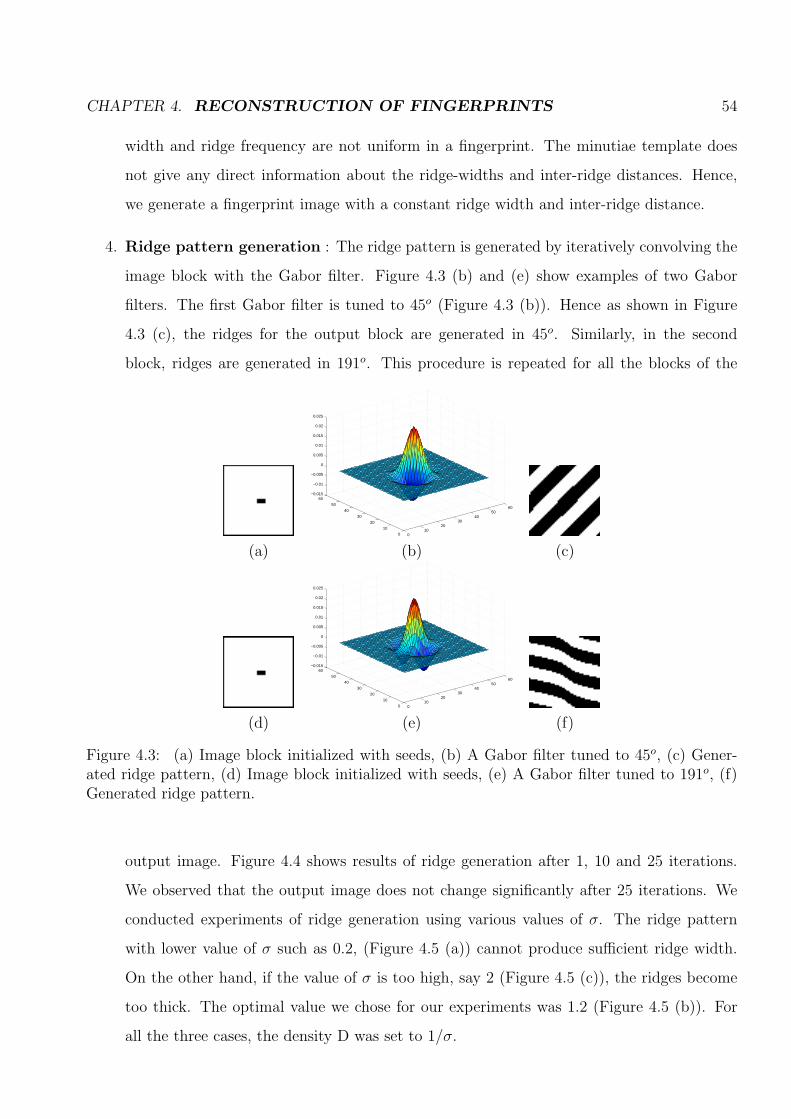
CHAPTER 4. RECONSTRUCTION OF FINGERPRINTS 54
width and ridge frequency are not uniform in a fingerprint. The minutiae template does
not give any direct information about the ridge-widths and inter-ridge distances. Hence,
we generate a fingerprint image with a constant ridge width and inter-ridge distance.
4. Ridge pattern generation : The ridge pattern is generated by iteratively convolving the
image block with the Gabor filter. Figure 4.3 (b) and (e) show examples of two Gabor
filters. The first Gabor filter is tuned to 45o (Figure 4.3 (b)). Hence as shown in Figure
4.3 (c), the ridges for the output block are generated in 45o. Similarly, in the second
block, ridges are generated in 191o. This procedure is repeated for all the blocks of the
010
2030
4050
60
0
10
20
30
40
50
60−0.015
−0.01
−0.005
0
0.005
0.01
0.015
0.02
0.025
(a) (b) (c)
010
2030
4050
60
0
10
20
30
40
50
60−0.015
−0.01
−0.005
0
0.005
0.01
0.015
0.02
0.025
(d) (e) (f)
Figure 4.3: (a) Image block initialized with seeds, (b) A Gabor filter tuned to 45o, (c) Gener-ated ridge pattern, (d) Image block initialized with seeds, (e) A Gabor filter tuned to 191o, (f)Generated ridge pattern.
output image. Figure 4.4 shows results of ridge generation after 1, 10 and 25 iterations.
We observed that the output image does not change significantly after 25 iterations. We
conducted experiments of ridge generation using various values of σ. The ridge pattern
with lower value of σ such as 0.2, (Figure 4.5 (a)) cannot produce sufficient ridge width.
On the other hand, if the value of σ is too high, say 2 (Figure 4.5 (c)), the ridges become
too thick. The optimal value we chose for our experiments was 1.2 (Figure 4.5 (b)). For
all the three cases, the density D was set to 1/σ.
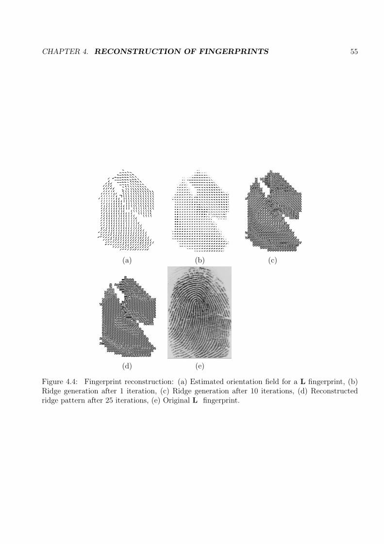
CHAPTER 4. RECONSTRUCTION OF FINGERPRINTS 55
(a) (b) (c)
(d) (e)
Figure 4.4: Fingerprint reconstruction: (a) Estimated orientation field for a L fingerprint, (b)Ridge generation after 1 iteration, (c) Ridge generation after 10 iterations, (d) Reconstructedridge pattern after 25 iterations, (e) Original L fingerprint.

CHAPTER 4. RECONSTRUCTION OF FINGERPRINTS 56
(a) (b) (c) (d) (e)
(a) (b) (c) (d) (e)
(a) (b) (c) (d) (e)
(a) (b) (c) (d) (e)
Figure 4.5: (a) Estimated Orientation Map θ̂, Output of ridge generation with (b) σ = 0.2, (c)σ = 1.2, (d) σ = 2, (e) Original fingerprint for classes A, L, R and W.

CHAPTER 4. RECONSTRUCTION OF FINGERPRINTS 57
We observed that for σ = 1.2, if we set D value to be very small such as 0.1 then the convolution
resulted in a black image (Figure 4.6 (a)). If this value is larger say 5, 10 or 15 then the ridge are
generated with larger density (Figure 4.6 (c), (d), (e)). We observed the value D = 1/σ resulted
in the acceptable ridge density. More results of reconstruction for other fingerprint classes are
(a) (b) (c) (d) (e) (f)
Figure 4.6: Output of ridge generation with (a) D = 0.1, (b) D = 0.2, (c) D = 1/σ, (d) D = 5,(e) D = 10, (f) D = 20.
shown in Figure 4.7. In this method, we do not have control over the minutiae generation.
(a) (b) (c)
(a) (b) (c)
Figure 4.7: (a) Estimated orientation map θ̂ , (b) Reconstructed fingerprint, (c) Original fin-gerprint of T, R, and W respectively.

CHAPTER 4. RECONSTRUCTION OF FINGERPRINTS 58
4.2.2 Reconstructing fingerprints using Streamlines and LIC
Streamlines and LIC (Line Integral Convolution) have been widely used for imaging arbitrary
two- and three-dimensional vector fields [50, 51]. Imaging vector fields has applications in science,
engineering, art, image processing, image rendering, animation and special effects. Examples of
vector fields include velocities of wind currents (e.g., for weather forecasting), results of fluid
dynamics simulation, blood flow, components of stress and strain in materials, etc. Hence,
algorithms that can image the directional information have wide application across both scientific
and artistic domains.
Here, we propose a novel application of streamlines and LIC for reconstructing fingerprints.
Given a vector field, streamlines are the curves that are tangential to the vector field at every
point. These are also called as integral curves as they are generated by integrating the vector
field. LIC is basically a texture synthesis technique that is used to visualize 2D data. Cabral
and Leedom [50] proposed LIC for imaging vector fields and to produce novel special effects
such as motion blurring in images. Figure 4.8 shows main steps for visualizing vector filed
using streamlines and LIC. For a given vector field, first the streamlines are generated. Using
streamlines and a spatially uncorrelated white noise image, LIC computes intensity values for
the coordinates of each streamline. It applies a one-dimensional filter to blur the noise image
along the streamlines resulting in a texture image which aids in the clear visualization the vector
field.
A fingerprint is an oriented texture pattern and, therefore, the use of streamlines and LIC for
generating the ridge structure is quiet appropriate; streamlines are used to generate the thinned
ridges whereas LIC is used to impart texture-like appearance to the ensuing ridges. The main
stages regenerating fingerprints are shown in Figure 4.9.
1. Computing orientation map θ̂ : Given a minutiae template, we first obtain the esti-
mated orientation map θ̂ using minutiae triplets described in Chapter 2.
2. Constructing Streamlines Using θ̂ : Consider an estimated orientation map θ̂ : R2 =>
R, (x, y) → θ̂(x, y), where (x, y) is an arbitrary location in θ̂. A streamline is a path in the
orientation map θ̂, whose tangent vectors coincide with θ̂ (Figure 4.10 (a)). Let P be a
point in the orientation map θ̂ and S be a streamline passing through P . Let the curvature

CHAPTER 4. RECONSTRUCTION OF FINGERPRINTS 59
White noise
Streamlines Vector field
LIC
Figure 4.8: Block diagram showing visualizing vector field using LIC.
Forming minutiae triplets
Estimating orientation
map
Computing streamlines
Line Integral
Convolution
Enhancing ridge map
Reconstructed fingerprint
Minutiae points
Figure 4.9: Block diagram showing the main stages of the proposed fingerprint reconstructionalgorithm.

CHAPTER 4. RECONSTRUCTION OF FINGERPRINTS 60
P
r(t) r(t+dt)
dr
S (r)
S
(x, y)
(a) (b)
Figure 4.10: (a) A streamline S tangent to orientation field θ̂, (b) Streamline originating froma seed point (x, y) in the vector field θ̂
at point P be due to a circle of radius r(t). Then the tangent dr at point P is given by,
dr
dt= θ̂[r(t)], (4.5)
where dt represents the next position. A numerical integration technique or interpolation
techniques can be used to solve this ordinary differential equation (ODE). Integrating
equation 4.5 yields,
r(t) = r(0) +
∫ t
0
θ̂(r(t))dt (4.6)
With the help of equation 4.6, a streamline can be initiated from an initial seed point and
grown using small steps of dt. There are various numerical integration techniques that
can be used to solve 4.6: (a) fixed step size integrators such as Euler; (b) non constant
or adaptive step size integrators such as cubic Hermite-interpolation; and (c) continuous
integration methods such as the fifth order Runge-Kutta integrator with adaptive step size.
In adaptive step size schemes, the value of dt is determined at each step of the integration
in order to keep the relative error within a specified tolerance. The accuracy of the ODE
solver determines the exactness of the resulting streamline. Consider dt = ti − ti−1, then
the error in streamline construction is O(dt)n, where n is the order of the ODE solver.
If we solve the above ODE for θ̂(x, y) with a seed point as (x, y), we get a streamline as
shown in Figure 4.10 (b). In order to generate streamlines for constructing ridge lines, the

CHAPTER 4. RECONSTRUCTION OF FINGERPRINTS 61
following issues have to be addressed: (a) selection of seed points, (b) criteria for streamline
termination, (c) distance between adjacent streamlines, and (d) generation of minutiae in
pre-determined positions.
(a) Seed point selection : The seed points are the pre-specified points in an orientation
map θ̂ from which the streamlines are originated. Figure 4.10 (b) shows an example
of seed point (x, y) from which a streamline is originated. Here, the seed point can
be considered to be a minutia (ridge ending). Thus, in order to generate minutiae at
desired locations, we use the minutiae locations as seed points. However, using only
minutiae as seed points results in the sparse distribution of streamlines over the image
plane (Figure 4.11 (b)). Thus, we also use the boundary points of θ̂ as seed points.
We observed that streamlines generated using only the border points as seed points
capture the global shape of the parent fingerprint as shown in Figure 4.11 (c). Thus
for fingerprint reconstruction, we use both, minutiae points and border points of θ̂ as
seed points.
The minutiae points in fingerprints tend to occur in clusters [26]. In such high
minutiae-density areas, seed points will occur in close proximity resulting in a clutter
of streamlines in the local region. To solve this problem, we place all the seed points
Si, i = 1. . . k+n (where k and n are the number of border points and minutiae respec-
tively) on a lattice of cell size Ds×Ds such that two seed points are at least Ds = 10
distance apart from each other as shown in Figure 4.12 (a). Due to this mapping,
a single grid point may correspond to multiple minutiae points. This prevents the
excessive proliferation of streamlines in a local region.
(b) Streamline construction : While most particle tracking algorithms (e.g., [52]) use
various numerical integration techniques to solve equation 4.6, we used the ‘stream3c’
function available in the Volume Visualization Toolbox of Matlab(7.0). It uses a linear
interpolation scheme for constructing streamlines. Once a streamline is initiated from
a seed point, the next position is obtained by updating its current position based
on the orientations of the immediate neighbors of the seed point. The streamline is
terminated if (a) it encounters a boundary point in the grid, or (b) if it arrives in the
vicinity of a minutia point. When a streamline is within a predetermined distance from

CHAPTER 4. RECONSTRUCTION OF FINGERPRINTS 62
(a) (b) (c) (d)
(a) (b) (c) (d)
(a) (b) (c) (d)
(a) (b) (c) (d)
Figure 4.11: (a) Estimated orientation map θ̂ with border points marked in ‘red’ color, (b)Streamlines generated from minutiae points as seed points, (c) Streamlines generated using borderpoints as seed points for classes, (d) Original fingerprint for A, R, L, W respectively.

CHAPTER 4. RECONSTRUCTION OF FINGERPRINTS 63
S S
m
Seedpoint
(a) (b) (c)
Figure 4.12: (a) Lattice of seed points (Dseed = 10), (b) Seed points ‘S’ overlaid on the orientationfield, θ̂, of an arch, (c) Streamline terminated near a minutia ‘m’.
a minutia point (in our case, 5 pixels apart), it is terminated as shown in Figure 4.12
(c). So a minutia (ridge ending) is generated if either a streamline initiates from that
point or another streamline appears in its proximity. In the current implementation,
we generate only ridge endings at the desired minutiae locations since it is assumed
that the ‘type’ of the minutia is not stored in the template.
It has been observed in the literature that a constant density of seed points do not nec-
essarily ensure an even distribution of the streamlines [50]. The generated streamlines
may not be evenly distributed, resulting in a frenzy of streamline activity in cer-
tain local regions. While several elegant techniques exist for creating evenly-spaced
streamlines (see [53], for example), we employ a simple technique to control inter-ridge
distances (Dr). We generate ridges with uniform inter-ridge distances over the entire
fingerprint image as we assume that the minutiae template does not give any infor-
mation about the inter-ridge distance of the parent fingerprint. During streamline
construction, if a streamline is in the proximity of another streamline (Dr = 5), then
it is discarded. This avoids the cluttering of streamlines in local regions (Figure 4.13).
Figure 4.14 shows the results of streamline generation for different fingerprint classes.
3. Generating ridge structure using LIC: As described above, using streamlines, thin
ridge lines for the estimated orientation map θ̂ can be generated. The intensity values
of ridge pixels shown in Figure 4.14 (c) are single valued i.e. ‘0’. In order to impart

CHAPTER 4. RECONSTRUCTION OF FINGERPRINTS 64
(a) (b) (c)
(a) (b) (c)
(a) (b) (c)
(a) (b) (c)
Figure 4.13: (a) Estimated orientation map θ̂, (b) Streamlines generated without controllingDr, (c) Streamlines generated by controlling Dr = 5, for A, R, L, W.

CHAPTER 4. RECONSTRUCTION OF FINGERPRINTS 65
(a) (b) (c)
(a) (b) (c)
(a) (b) (c)
(a) (b) (c)
Figure 4.14: (a) Minutiae plot, (b) Estimated orientation map θ̂, (c) Streamlines

CHAPTER 4. RECONSTRUCTION OF FINGERPRINTS 66
texture-like appearance to the ridges, we use Linear Integral Convolution (LIC). Given a
streamline S, the LIC technique involves calculating the intensity of all pixels constituting
the streamline. It locally blurs an uncorrelated input texture image such as white noise,
along the path of the streamlines to impart a dense visualization of the flow field. Consider
a pixel at location x0 = S(p0) on the streamline. Then its intensity is computed using
one-dimensional filtering as,
I(x0) =
∫ p0+L
p0−L
k(p− p0)TS(p)dp (4.7)
where, T is a texture (white noise image). The kernel, k, is a one-dimensional low-pass
filter with L = 25 pixels. The convolution results in the generation of ridge-like patterns
whose orientations correspond to the predicted vector field (Figure 4.15). The filter length
‘L’ determines how much the texture is smeared in the direction of the vector field. Due
(a) (b) (c)
Figure 4.15: Lending texture to a streamline using LIC: (a) White noise image, T, (b) ConvolvingT with a streamline, (c) Result of LIC.
to LIC, the binary image generated using streamlines is converted to a gray scale image
(Figure 4.16 (b)).
4. Enhancing the ridge map: Although LIC provides texture-like appearance to the thin
ridges (streamlines), the ridges are still one-pixel thick. In order to increase the ridge width,
we first use a lowpass filter to smooth the texture image generated using LIC and then
perform histogram equalization of the ridge structure for contrast enhancement as shown
in Figure 4.16 (c).
4.2.3 Comparing two reconstruction schemes
Figure ?? compares the two techniques for fingerprint regeneration using: (a) Gabor-filters,
and (b) Streamlines and LIC. Unlike Gabor filters, with streamlines and LIC, the reconstructed

CHAPTER 4. RECONSTRUCTION OF FINGERPRINTS 67
(a) (b) (c) (d)
Figure 4.16: (a) Estimated orientation map θ̂, (b) Result of applying LIC, (c) Enhanced finger-print using a 5× 5 lowpass filter, (d) The original fingerprint.
ridge pattern exhibits shape characteristics of the parent fingerprint significantly. It also enables
to place the minutiae at desired locations and with desired orientations in the reconstructed
fingerprint.
The reconstructed fingerprints using minutiae are partial. This is because a minutiae template
may not capture all the global properties of the parent fingerprint. We demonstrated that it is
indeed possible to reconstruct the at least those parts of the fingerprint which are used for
authentication.
(a) (b) (c) (d)
Figure 4.17: (a) Minutiae plot, (b) Estimated orientation map θ̂, (c) Regenerated fingerprint usingGabor filters, (d) Regenerated fingerprint using LIC

CHAPTER 4. RECONSTRUCTION OF FINGERPRINTS 68
4.2.4 Spoofing of fingerprint authentication system
Figure 4.18 shows an overlay of original and reconstructed fingerprints of A and L. Visually, it
is evident that the reconstructed fingerprints are consistent with the underlying ridge structures.
We conducted few experiments to verify if the reconstructed ridge structure may be used to
(a) (b)
Figure 4.18: Overlay of original (magenta) and reconstructed (blue) fingerprints for two minutiaetemplates.
spoof an authentication system. The authentication system used for fingerprint matching was
VeriFinger 4.1 SDK, developed by Neurotechnologija 1. The software has the ability to process
fingerprint images (apart from the live samples captured by sensor system) supported by the
SDK. Given an input fingerprint image, the software first enhances the image and converts it
into a binary image using certain image processing routines (Figure 4.19), extracts minutiae from
the enhanced images and stores minutiae positions (x, y) and the orientations (θ) in the template.
It is evident from Figure 4.19 (d) that the enhancement algorithm employed by the software also
removes certain parts of the ridges of the reconstructed fingerprint in the regions with low ridge
density. On matching, it releases the match (similarity) score. Being a commercial software much
information about its minutiae extraction and matching algorithm is not available. To spoof the
authentication system, we used NIST-4f and FVC 2002 DB3 databases. NIST-4f contains 2000
fingerprints (500 fingerprints per class) of size (512 × 512) and one fingerprint per individual
whereas DB3 contains 110 users and 8 fingerprints per user. First, the fingerprint images are
given as an input to the software and minutiae templates are created. For each template, the
orientation map, θ̂ is estimated using minutiae triplets. Using streamlines and LIC, the ridge
structure of the parent fingerprint corresponding to each template is created.
1http://www.neurotechnologija.com
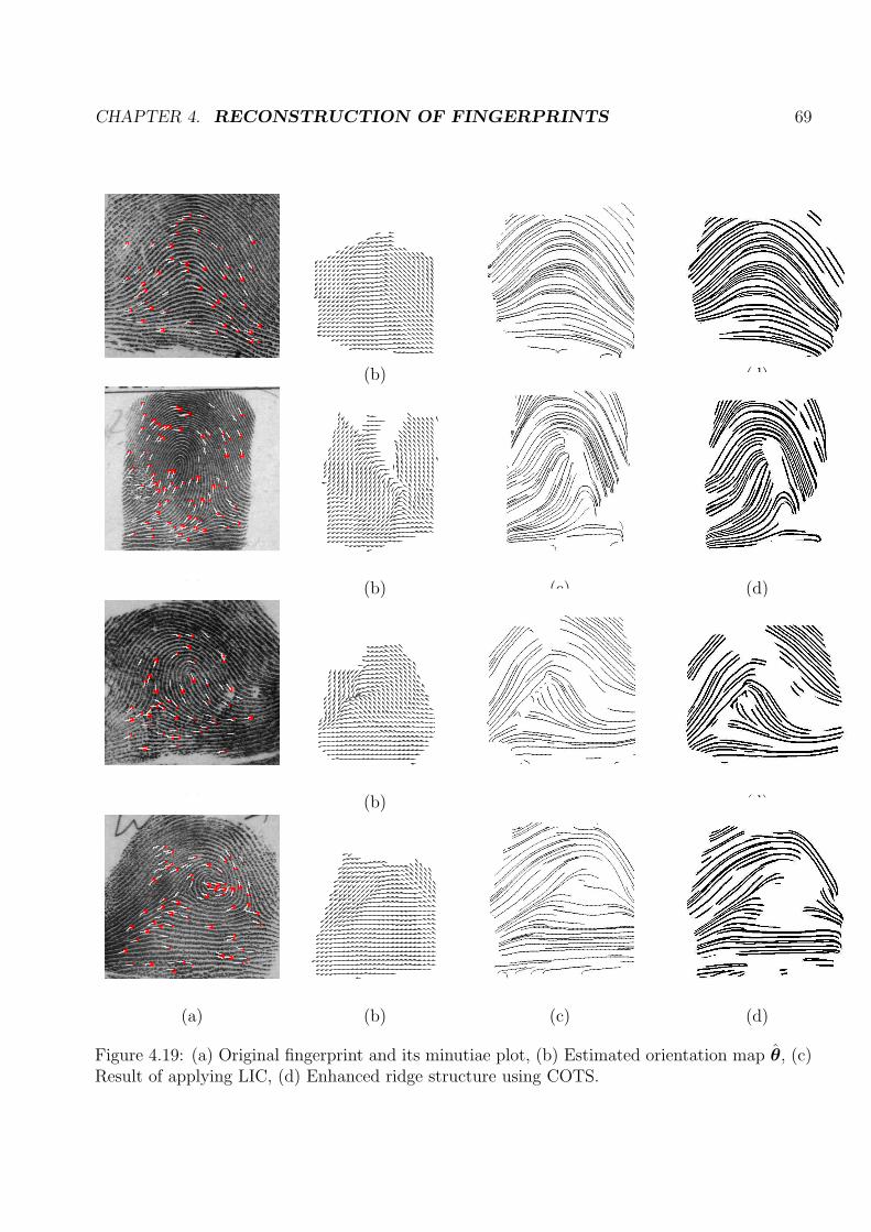
CHAPTER 4. RECONSTRUCTION OF FINGERPRINTS 69
(a) (b) (c) (d)
(a) (b) (c) (d)
(a) (b) (c) (d)
(a) (b) (c) (d)
Figure 4.19: (a) Original fingerprint and its minutiae plot, (b) Estimated orientation map θ̂, (c)Result of applying LIC, (d) Enhanced ridge structure using COTS.

CHAPTER 4. RECONSTRUCTION OF FINGERPRINTS 70
We considered two matching scenarios. In the first scenario, each reconstructed fingerprint
was matched against every original fingerprint in the database. In the second scenario, it is
assumed that the class of the parent fingerprint is known. Then, the reconstructed fingerprint is
matched with all the original fingerprints of this class only. For each reconstructed fingerprint, the
top matches are recorded, and the CMC (Cumulative Match Characteristics) curve is generated
to summarize the identification performance. The CMC graph plots the identification rate as
a function of the number of top matches (ranks) [54]. Figure 4.20 (e) shows the CMC curves.
It is evident that W gives lower identification rates. A fingerprint of W class is characterized
0 5 10 15 20 25 300
10
20
30
40
50
60
Ranks
Iden
tifi
cati
on
Rat
e
Entire NIST−4f
A
L
R
W
Figure 4.20: CMC curves when class of reconstructed fingerprint is (a) unknown (matched against allfingerprints of NIST-4f database), (b) known (matched against all fingerprints of the same class only).
by high ridge activity near core and delta region. The orientation estimation algorithm cannot
capture the ridge orientations near the core or delta region correctly. This results in the incorrect
generation of streamlines in this region. Hence, the minutiae points in this region may not match
with that of the original fingerprint resulting in lower identification rate. Also, during streamline
construction, we do not permit a streamline to be generated too close to any other existing
streamline. As the inter-ridge distance is assumed to be absent in the minutiae template, we
use a constant inter-ridge distance for the entire fingerprint. Thus, very few streamlines are
generated in region with high minutiae density resulting in missing minutiae in the reconstructed
fingerprint.
For the DB3 database, we performed matching using the entire database. The CMC curve
for DB3 database (Figure 4.21) indicates very low identification rates. The fingerprints in this

CHAPTER 4. RECONSTRUCTION OF FINGERPRINTS 71
0 5 10 15 20 25 302
4
6
8
10
12
14
16
Ranks
Iden
tifi
cati
on
Rat
e
CMC curve for DB3 FVC2002 database
Figure 4.21: CMC curves when reconstructed fingerprint matched against all the fingerprints inFVC2002 DB3 database).
database are dab prints of size 300 × 300. They contain relatively small number of minutiae
points. Thus the estimated orientation map θ̂ has many empty cells (no estimation porssible)
resulting in short streamlines as shown in Figure 4.22. When the reconstructed output is given
as input to the VeriFinger software, it performs certain preprocessing techniques for enhancing
the fingerprint. In some cases, in reconstructed fingerprint, if the ridge density around a minutia
is low, the software removes certain portion of that ridge on which the minutia resides. This
results in removing genuine minutiae and forming spurious minutiae. Thus, for reconstructed
fingerprints from the DB3 database, very few minutiae are extracted resulting in low matching
scores. But for the rolled prints in the NIST-4f database, due to larger sensing area, they
have more number of minutiae. Thus θ̂ corresponding to these fingerprints contains relatively
more orientations as shown in Figure 4.23 (a). This aids in generating dense streamlines. The
VeriFinger software therefore extracts more minutiae points (Figure 4.23 (c)) resulting in better
match scores.

CHAPTER 4. RECONSTRUCTION OF FINGERPRINTS 72
(a) (b) (c) (d)
(d) (e) (f) (g)
(h) (i) (j) (k)
Figure 4.22: Estimated orientation map θ̂ [(a), (d), (h)], Reconstructed fingerprint [(b), (e),(i)], Enhanced image by VeriFinger and its extracted minutiae [(c), (f), (j)], Original fingerprint[(d), (g), (k)] for 3 fingerprints of DB3 FVC2002 database.
(a) (b) (c) (d)
Figure 4.23: (a) Estimated orientation map θ̂, (b) Reconstructed fingerprint, (c) Enhancedimage by VeriFinger and its extracted minutiae, (d) Original A fingerprint of NIST 4f Database.

73
Chapter 5
Summary and Future work
“First of all, it is important to remember that absolute security does not exist: given funding,
willpower and the proper technology, nearly any security system can be compromised.” [55].
Biometrics is a constantly growing industry and fingerprint recognition represents one of the
most advantageous methods for authentication. Most fingerprint authentication systems extract
and store the minutiae template of a finger after the enrollment process. It has been commonly
assumed that the decrypted minutiae template does not reveal significant information about
the parent fingerprint. In this thesis, we dispel this notion by demonstrating that the minutiae
information may be used to derive the ridge structure of the underlying fingerprint. The proposed
scheme first estimates the orientation of ridges at discrete points in a grid by considering minutiae
triplets in local regions. Experiments suggest that the estimated orientations are quite consistent
with the true ridge flow. This observation can be beneficial in applications like smart-cards,
where the generated orientation field can be used in conjunction with the minutiae points to
improve the matching performance. This estimated orientation field is then used to generate the
ridge structure of the parent fingerprint by invoking streamlines and LIC. The use of streamlines
permits us to control the location, type and number of minutiae in the generated ridge map. This
process can also be used as an alternative technique for generating synthetic fingerprints with
minutiae placed at pre-determined locations (unlike SFINGE [43] where minutiae are randomly
generated). The reconstructed ridge structure is observed to be ”visually” similar to that of the
parent fingerprint. It may be used to spoof a fingerprint system. The exact reconstruction of
the target fingerprint image is not possible as the minutiae template may not reveal important
global ridge shapes. We also demonstrated that the class of a fingerprint may be inferred using

CHAPTER 5. SUMMARY AND FUTURE WORK 74
the minutiae information alone. Thus, this research provides an insight into the individuality of
fingerprints based on their minutiae content. Further, it demands the design of effective template
security schemes.
We assume that the template stores minimum information about the minutiae such as x,
y and theta. In practice, along with this basic information, the template may also store other
information such as core and delta points, minutia type, information abut neighboring minutiae,
etc. [56]. Also, the fingerprints reconstructed using minutiae points can be used to masquerade
not only the minutiae based authentication systems but also systems that are based on the ridge
pattern of fingerprints. So proper storage and security of the template is important for the
reliability and robustness of the system, and for users’ trust because the acceptance of biometric
systems will now depend on how securely the biometric template is stored. This research opens
door for investigating methods for securing templates or making them more robust.
Encrypting the biometric template is one possible solution for masquerade attack but de-
crypting a template is not an impossible task. Thus, merely encrypting the template will not
prevent this attack. Various methods for improving security of biometrics and stored biomet-
ric templates have been proposed in literature. Ratha et al. [57] introduced the concept of
“cancellable biometrics”. In this approach, the biometric signal is intentionally distorted before
feature extraction. The biometric signal is distorted in the same fashion at each presentation,
for enrollment and for every authentication. If one variant of the transformed biometric data is
compromised, then the transform function can simply be changed. The distortion transforms are
chosen to be non-invertible. So even if the transform function is known and the resulting trans-
formed biometric data are known, the original biometrics cannot be recovered. Jain and Uludag
[58] proposed a biometric watermarking technique which can increase the security of fingerprint
images by hiding eigen face templates into them. Also, Linnartz and Tuyls [59] demonstrated
the use of delta-contracting and epsilon-revealing functions as preprocessors for constructing
helper data that is used in a way that no information about the biometric templates is leaked to
imposters.
Besides all these approaches, one potential approach to prevent masquerade attack on a
minutiae based fingerprint system, would be to systematically exclude certain salient minutiae
from the template that are critical to image reconstruction without drastically affecting the
matching performance.

CHAPTER 5. SUMMARY AND FUTURE WORK 75
The biometric systems using identifiers other than fingerprints such as iris, hand, voice are
generally template-based, i.e., they store salient features of the biometric sample in the database
and use it later for matching. As Hill points out [15] the masquerade attack is applicable to
many other biometrics other than fingerprints or perhaps all of them.
5.1 Future work
More sophisticated techniques for estimating ridge orientation from minutiae points need to
be explored. Presently, the orientation scheme makes use of minutiae triplets in the local regions.
The relationship between these triplets can be used to get global information about the ridge
orientations. Also, techniques to estimate the orientations in the region where ‘valid’ triplets did
not form, needs to be explored. Presently, the estimated ridge orientations in the core region
can not capture important ridge properties such as circular pattern in W and recurving loops
(L, R). Along with minutiae information, if information about core and delta is also available
then a more sophisticated technique needs to be designed. The information about core and delta
position can give information about class of the fingerprint which might aid in improving the
orientation estimation.
Using the inferred class information from minutiae templates, the streamline construction
process can be moderated since minutiae properties - such as their occurrence and density -
varies across classes. For example, each class can have a different seeding strategy. Verma [60] et
al. discuss a seed placement strategy based on flow features in the data set. The seeds are placed
in the vicinity of critical points in the flow field to capture important flow patterns. To improve
the accuracy of streamline computation, we plan to use more accurate numerical integration
methods like the fifth order Runga-Kutta technique.
In future, to further improve the identification performance, the fingerprints can be recon-
structed using an iterative hill-climbing approach (See Figure 5.1). Here, it is assumed that
the fingerprint matching software releases a match score. After reconstructing fingerprint us-
ing streamlines and LIC, the minutiae template is extracted from reconstructed fingerprint and
matched against the minutiae template stored in the database using the matching software. The
software releases the match score indicating similarity between the two minutiae templates. The
fingerprint reconstruction process can then be modified to increase the match score.
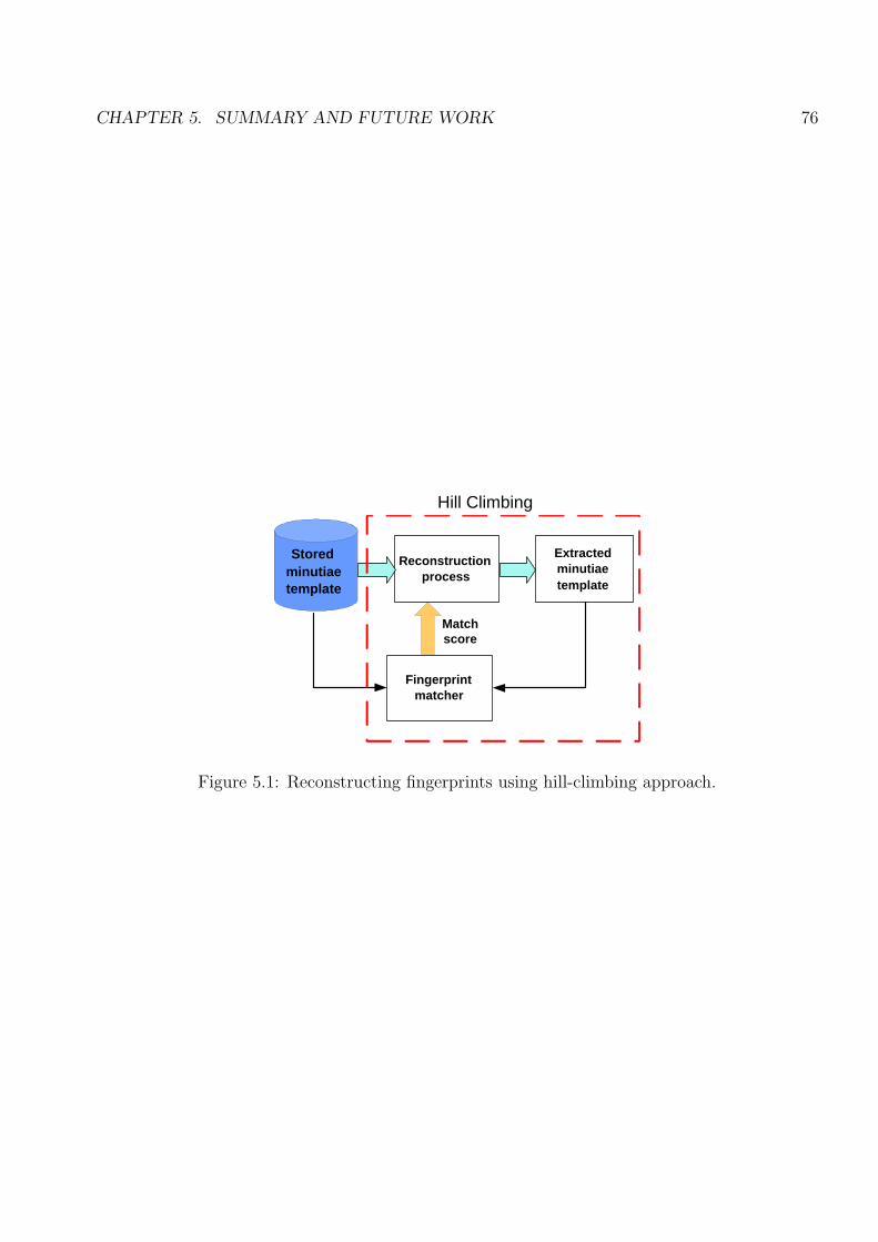
CHAPTER 5. SUMMARY AND FUTURE WORK 76
Reconstruction process
Extracted minutiae template
Fingerprint matcher
Match score
Stored minutiae template
Hill Climbing
Figure 5.1: Reconstructing fingerprints using hill-climbing approach.

77
References
[1] N. Ratha, J. Connell, and R. Bolle, “Analysis of minutiae matching strength,” Proceedingsof International Conference on Audio and Video-Based Biometric Person Authentication(3rd), vol. 24, pp. 223 – 228, 2001.
[2] E. Henry, Classification and Uses of Fingerprints, Routledge, London, 1900.
[3] A. K. Jain and S. Minut, “Hierarchical kernel fitting for fingerprint classification and align-ment,” Proc. of International Conference on Pattern Recognition (16th), vol. 2, pp. 469 –473, Aug 2002.
[4] D. Maltoni, D. Maio, A. K. Jain, and S. Prabhakar, Handbook of fingerprint recognition,1st ed. New York, Berlin Heidelberg: Springer-Verlag, 2003.
[5] J. Wayman, “Fundamentals of biometric authentication technologies.”
[6] “Finger minutiae format for data interchange, ANSI/INCITS 378,” American National Stan-dard for Information Technology, [Online] Available at www.incits.org, Tech. Rep., 2004.
[7] A. Moenssens, Fingerprint Techniques. London: Chilton Book Company, 1971.
[8] D. A. Stoney, “Quantitative assessment of fingerprint individuality,” Ph.D. dissertation,University of California, Davis, 1985.
[9] A. K. Jain, L. Hong, and R. Bolle, “On-line fingerprint verification,” IEEE Trans on PatternAnalysis Machine Intelligence, vol. 19, no. 4, pp. 302–314, April 1997.
[10] S. Pankanti, S. Prabhakar, and A. K. Jain, “On the individuality of fingerprints,” IEEETransactions on Pattern Analysis and Machine Intelligence, vol. 24, no. 8, pp. 1010–1025,2002.
[11] N. Ratha, J. Connell, and R. Bolle, “Biometrics break-ins and band-aids,” Pattern Recog-nition Letters, vol. 24, pp. 2105–2113, Sep 2003.
[12] U. Uludag and A. Jain, “Attacks on biometric systems: A case study in fingerprints,” Proc.SPIE-EI, Security, Seganography and Watermarking of Multimedia Contents VI, pp. 622–533, Jan 2004.
[13] U. Uludag and A. K. Jain, “Fingerprint minutiae attack system,” Biometrics ConsortiumConference, Sep 2004.
[14] A. Adler, “Can images be regenerated from biometric templates?” Biometrics ConsortiumConference, Sep 2003.

REFERENCES 78
[15] C. Hill, “Risk of masquerade arising from the storage of biometrics,” Master’s thesis, Aus-tralian National University, 2001.
[16] C. Soutar, “Biometric system security.”
[17] “Face recongition vendor test 2002.”
[18] “BioAPI speicification (version 1.1),” BioAPI Consortium, Tech. Rep., 2001.
[19] A. Adler, “Images can be generated from quantized biometric match score data,” Proc. Can.Conf. Elec. Comp. Eng., Niagara Falls, May 2004.
[20] B. Sherlock and D. Monro, “A model for interpreting fingerprint topology,” Pattern Recog-nition, vol. 26, no. 7, pp. 1047–1055, 1993.
[21] I. B. Group, “Generating images from templates,” I.B.G. White Paper, Tech. Rep., 2002.
[22] N. Ratha, J. Connell, and R. Bolle, “Adaptive flow orientation-based feature extraction infingerprint images,” Pattern Recognition, vol. 28, no. 11, pp. 1657–1672, 1995.
[23] A. Rao, “A taxonomy for texture description and identification,” Springer-Verlag, 1990.
[24] Z. M. Kovacs-Vajna, “A fingerprint verification system based on triangular matching anddynamic time warping,” IEEE Transactions on Pattern Analysis and Machine Intelligence,vol. 22, pp. 1266 – 1276, Nov 2000.
[25] R. Germain, A. Califano, and S. Colville, “Fingerprint matching using transformation pa-rameters clustering,” IEEE Computational Science and Engineering, vol. 4, no. 4, pp. 42 –49, 1997.
[26] C. Kingston, “Probabilistic analysis of partial fingerprint patterns,” Ph.D. dissertation,University of California, Berkeley, 1964.
[27] R. Cappelli, A. Lumini, D. Maio, and D. Maltoni, “Fingerprint classification by direc-tional image partitioning,” IEEE Transcations on Pattern Analysis and Machine Intelli-gence, vol. 21, pp. 402–421, 1999.
[28] G. Candela, P. Grother, C. Watson, R. Wilkinson, and C. Wilson, “PCASYS - a pattern-level classification automation system for fingerprints,” NIST TR 5647, Tech. Rep., Aug1995.
[29] A. Jain, S. Parabhakar, and L. Hong, “A multichannel approach to fingerprint classification,”IEEE Transcations on Pattern Analysis and Machine Intelligence, vol. 21, pp. 348–359, 1999.
[30] L. Hong, “Automatic personal identification using fingerprints,” Ph.D. dissertation, Michi-gan State University, 1998.
[31] M. Chong, T. Ngee, L. Jun, and R. Gay, “Geometric framework for fingerprint image clas-sification,” Pattern Recognition, vol. 30, no. 9, pp. 1475–1488, 1997.
[32] A. Senior, “A combination fingerprint classifier.” IEEE Transactions on Pattern Analysisand Machine Intelligence, vol. 23, no. 10, pp. 1165–1174, 2001.

REFERENCES 79
[33] C. Wilson, G. Candela, and C. Watson, “Neural network fingerprint classification,” Journalof Artificial Neural Networks, vol. 1, no. 2, pp. 203–228, 1994.
[34] K. Karu and A. Jain, “Fingerprint classification,” Pattern Recognition, vol. 29, pp. 389–404,1996.
[35] B. Cho, J. Kim, I. Bae, I. Bae, and K. Yoo, “Core-based fingerprint image classification,”Proc. Int. Conf. on Pattern Recognition (15th), vol. 2, pp. 863–866, 2000.
[36] Y. Yao, P. Frasconi, and M. Pontil, “Fingerprint classification with combination of supportvector machines.” Proc. Int. Conf. on Audio- and Video-Based Biometric Person Authenti-cation (3rd), pp. 253–258, 2001.
[37] A. Ross, J. Shah, and A. Jain, “Towards reconstructing fingerprints from minutiae points,”Proc. of SPIE Conference on Biometric Technology for Human Identification II, pp. 68–80,2005.
[38] T. Roxburgh, “On the evidential value of fingerprints,” Sankhya: Indian Journal of Statis-tics, pp. 189–214, 1993.
[39] F. Galton, Finger Prints. London: McMillan, 1892.
[40] D. H. Ballard, “Generalizing the hough transform to detect arbitrary shapes,” Patternrecognition, vol. 13, no. 3, pp. 111–112, 1997.
[41] C. Champod and P. Margot, “Computer assisted analysis of minutiae occurrences on fin-gerprints,” Proc. Int’l Symp. Fingerprint Detection and Identification, p. 305, 1996.
[42] L. Hong, Y. Wan, and A. K. Jain, “Fingerprint image enhancement: Algorithm and per-formance evaluation,” IEEE Trans on Pattern Analysis and Machine Intelligence, vol. 20,no. 8, pp. 777–789, Aug 1998.
[43] R. Cappelli, D. Maio, and D. Maltoni, “Synthetic fingerprint image generation,” Proc. of15th Int. Conf. on Advances in Pattern Recognition, vol. 3, no. 5, pp. 475–478, 2000.
[44] “Optel, Poland.”
[45] S. Novikov and G. Glushchenko, “Fingerprint ridges structure generation models,” Proc.SPIE, Sixth International Workshop on Digital Image Processing and Computer Graphics,vol. 3346, pp. 270–274, 1998.
[46] P. Vizcaya and L. Gerhardt, “Nonlinear orientation model for global description of finger-prints,” Pattern Recognition, vol. 29, pp. 1221–1231, 1996.
[47] L. Hong, Y. Wan, and A. Jain, “Fingerprint image enhancement: Algorithm and per-formance evaluation,” IEEE Transcations on Pattern Analysis and Machine Intelligence,vol. 20, pp. 777–789, Aug 1998.
[48] R. Cappelli, D. Maio, and D. Maltoni, “Modeling plastic distortion in fingerprint images,”Proc. International Conference on Pattern Recognition 2001, pp. 369 – 376, Mar 2001.
[49] I. Jolliffe, Principal Component Analysis. Springer-Verlag, 1996.

REFERENCES 80
[50] B. Cabral and L. Leedom, “Imaging vector fields using line integral convolution,” in Pro-ceedings of the 20th annual conference on Computer graphics and interactive techniques,1993, pp. 263 – 270.
[51] D. Laidlaw, R. Kirby, C. Jackson, J. Davidson, T. Miller, M. Silva, W. Warren, and M. Tarr,“Comparing 2D vector field visualization methods: A user study,” in IEEE TransactionsOn Visualization And Computer Graphics, vol. 11, no. 1, Jan/Feb 2005, pp. 59–70.
[52] A. Sadarjoen, T. Walsum, A. Hin, and Post, “Particle tracing algorithms for 3D curvilineargrids,” In Fifth Eurographics Workshop on Visualization and Scientific Computing, 1994.
[53] B. Jobard and R. Wilfrid, “Creating evenly-spaced streamlines of arbitrary density,” Visual-ization in Scientific Computing ’97, Proceedings of the Eurographics Workshop in Boulogne-sur-Mer, 1997.
[54] H. Moon and P. Phillips, “Computational and performance aspects of pca-based face-recognition algorithms.” Perception, vol. 30, pp. 303 – 321, 2001.
[55] “Fingerprint recognition based on silicon chips,” Atmel Coorporation, [Online] Available athttp://www.atmel.com/atmel/acrobat/wpv01.pdf, White Paper, 2001.
[56] “Minutiae interoperability exchange test 2004 (MINEX04),” NIST, [Online] Available athttp://fingerprint.nist.gov/minex04/Home.html, Tech. Rep., 2004.
[57] V. Verma, D. Kao, and A. Pang, “Enhancing security and privacy in biometrics-basedauthentication systems,” IBM Systems Journal, vol. 40, no. 3, 2001.
[58] A. Jain and U. Uludag, “Hiding biometric data,” IEEE Transactions on Pattern Analysisand Machine Intelligence, vol. 25, no. 11, pp. 1494–1498, Nov 2003.
[59] J. Linnartz and P. Tuyls, “New shielding functions to enhance privacy and prevent misuseof biometric templates,” Proc. of Audio- and Video-based Person Authentication, 2003.
[60] V. Verma, D. Kao, and A. Pang, “A flow-guided streamline seeding strategy,” IEEE Visu-alization archive Proceedings of the conference on Visualization ’00, pp. 163–170, 2000.


![FM Model Based Fingerprint Reconstruction from … Model Based Fingerprint Reconstruction from Minutiae Template 545 Hill [1] proposed a technique to determine the fingerprint structure](https://img.pdfslide.us/doc/110x75/5ad98d817f8b9a52528bb155/fm-model-based-fingerprint-reconstruction-from-model-based-fingerprint-reconstruction.jpg)