Embed Size (px)
Citation preview
Hans-Wilhelm Warnke Rheinmetall Defence Electronics
Mission Equipment Brüggeweg 54, D-28309 Bremen
GERMANY
ABSTRACT
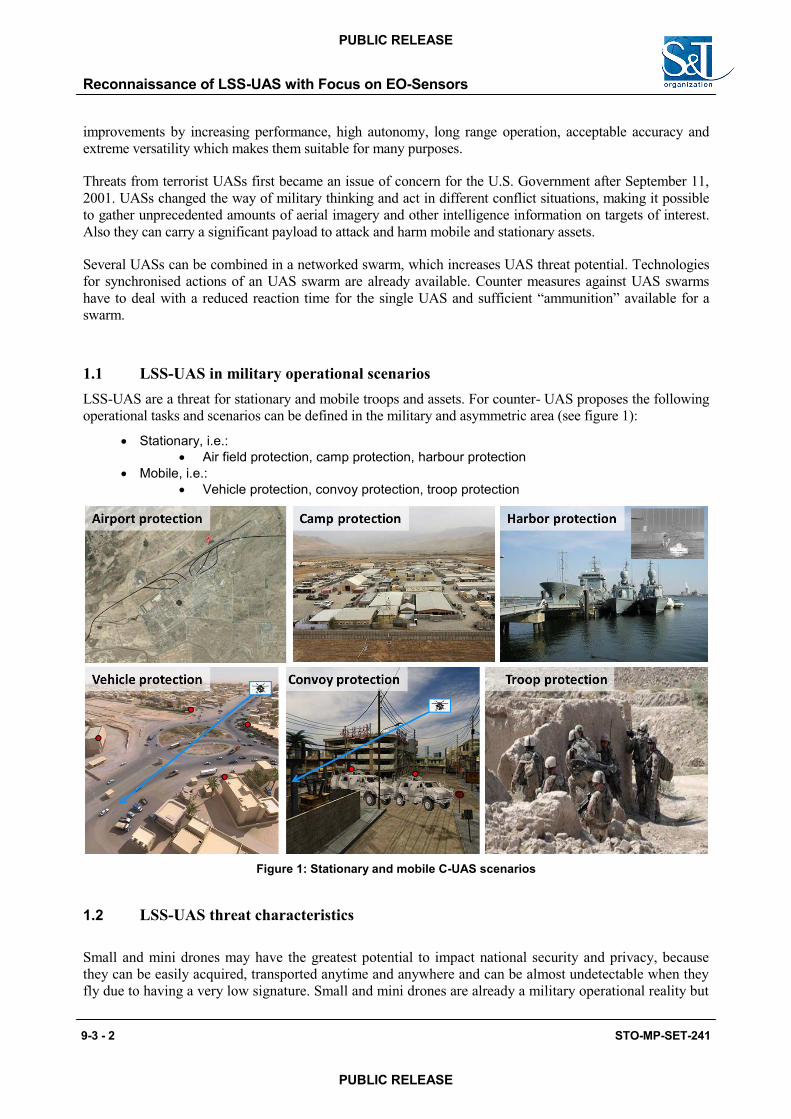
Low, Slow and Small Unmanned Aerial Systems (LSS-UAS) are powerful, cheap, and can be purchased and operated by everyone. Modifications and add-ons for different operational tasks can easily be configured. LSS-UAS with surveillance sensors or explosive ordnance as payload create new challenges for today’s war fighters.
Relevant sensors for the detection of LSS-UAS are Radars, EO-surveillance sensors (IRST- Infra Red Search & Track) and Passive Emitter Localization sensors (PEL). Methods based on single sensors do not perform satisfactory and intelligent sensor data fusion is necessary in order to improve detection. The threat classification and identification may be done by EO sensors and can be assisted by Radar, ESM and Acoustics.
Current GBAD systems are not designed for LSS-UAS threats. Military applications in different scenarios such as “Stationary Asset Defence (SAD)” and Mobile Force Protection (MFP)” need specific adaption of system configurations and sensor design.
This paper and the presentation concentrates on detection and verification of LSS-UAS threats with EO sensors (IRST, cooled and uncooled IR thermal imagers, day sight cameras) in conjunction with powerful image processing functions (detect, track, classify, identify). EO- sensor configurations for stationary asset defence and mobile force protection are being described and the results of performed trials explained.
Further on, exemplary operational scenarios, improvement of algorithms by combination of different sensors, results from relevant NIAG studies, C-UAS trials and relevant German R&T studies will be presented. Also the description of standardization activities for sensors, interfaces and plug-in functionality (based on NGVA = NATO Generic Vehicle Architecture) as a military demand for mission component interchangeability and lower serial production costs is content of the paper.
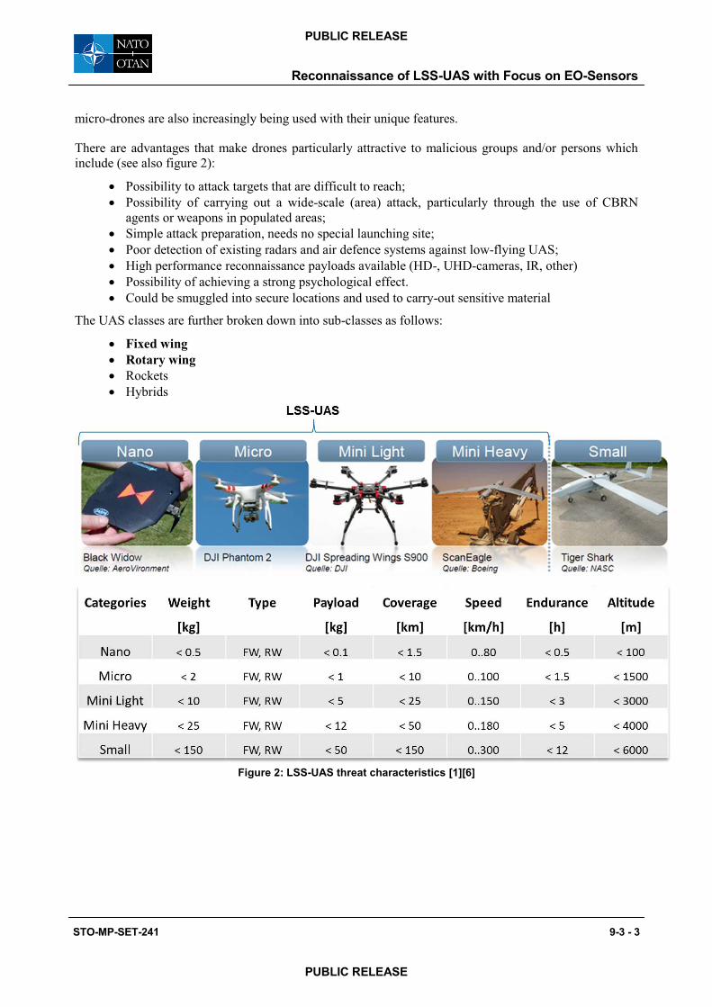
1.0 LSS-UAS threats Low, Slow and Small- Unmanned Aerial Systems (LSS-UASs) are commercial available and can be operated easily by everyone. These LSS-UAS are typically equipped with sensors and electronics to assist the remote operator for easy control of the LSS-UAS flight path and delivery of First Person View (FPV) Video. Beside leisure activities these LSS-UAS can also be used for spying, terrorism and military purposes. LSS-UAS are used for reconnaissance and strike of targets without putting pilots live at risk.
LSS-UASs use advanced technological equipment and the research on these devices is providing continuous
STO-MP-SET-241 9-3 - 1
PUBLIC RELEASE
PUBLIC RELEASE
Reconnaissance of LSS-UAS with Focus on EO-Sensors
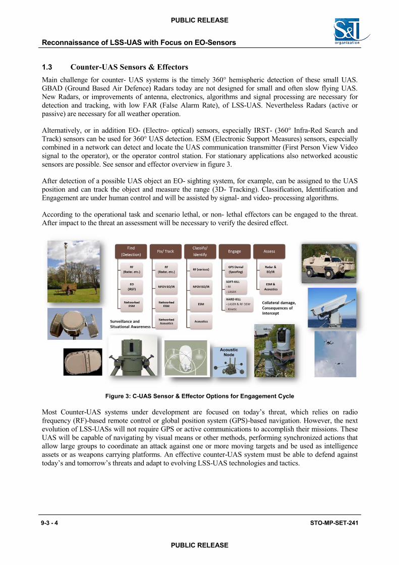
1.4 EO/IR- Sensors for counter-UAS application
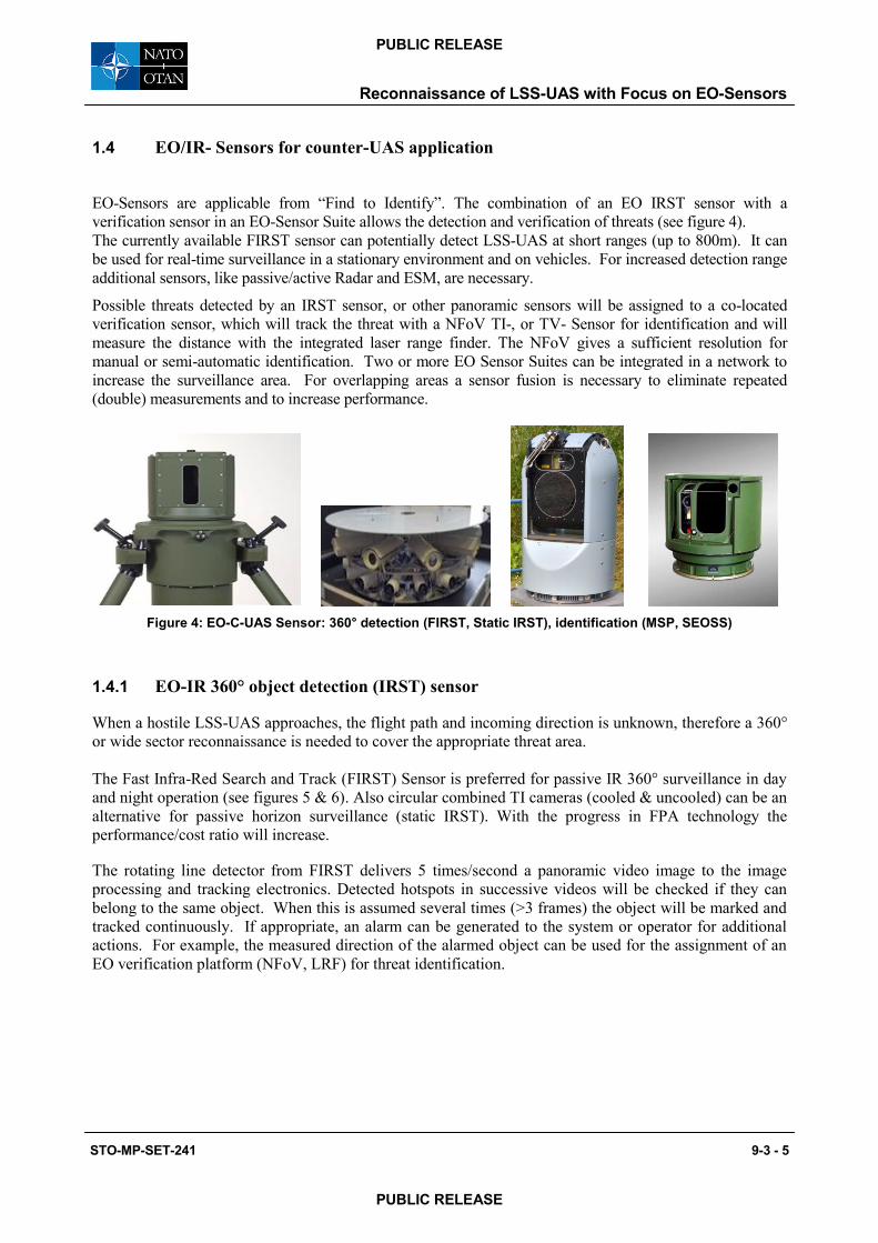
EO-Sensors are applicable from “Find to Identify”. The combination of an EO IRST sensor with a verification sensor in an EO-Sensor Suite allows the detection and verification of threats (see figure 4). The currently available FIRST sensor can potentially detect LSS-UAS at short ranges (up to 800m). It can be used for real-time surveillance in a stationary environment and on vehicles. For increased detection range additional sensors, like passive/active Radar and ESM, are necessary.
Possible threats detected by an IRST sensor, or other panoramic sensors will be assigned to a co-located verification sensor, which will track the threat with a NFoV TI-, or TV- Sensor for identification and will measure the distance with the integrated laser range finder. The NFoV gives a sufficient resolution for manual or semi-automatic identification. Two or more EO Sensor Suites can be integrated in a network to increase the surveillance area. For overlapping areas a sensor fusion is necessary to eliminate repeated (double) measurements and to increase performance.
Figure 4: EO-C-UAS Sensor: 360° detection (FIRST, Static IRST), identification (MSP, SEOSS)
1.4.1 EO-IR 360° object detection (IRST) sensor
When a hostile LSS-UAS approaches, the flight path and incoming direction is unknown, therefore a 360° or wide sector reconnaissance is needed to cover the appropriate threat area.
The Fast Infra-Red Search and Track (FIRST) Sensor is preferred for passive IR 360° surveillance in day and night operation (see figures 5 & 6). Also circular combined TI cameras (cooled & uncooled) can be an alternative for passive horizon surveillance (static IRST). With the progress in FPA technology the performance/cost ratio will increase.
The rotating line detector from FIRST delivers 5 times/second a panoramic video image to the image processing and tracking electronics. Detected hotspots in successive videos will be checked if they can belong to the same object. When this is assumed several times (>3 frames) the object will be marked and tracked continuously. If appropriate, an alarm can be generated to the system or operator for additional actions. For example, the measured direction of the alarmed object can be used for the assignment of an EO verification platform (NFoV, LRF) for threat identification.
Reconnaissance of LSS-UAS with Focus on EO-Sensors
STO-MP-SET-241 9-3 - 5
PUBLIC RELEASE
PUBLIC RELEASE
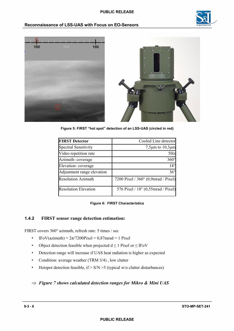
Figure 5: FIRST “hot spot” detection of an LSS-UAS (circled in red)
FIRST Detector Cooled Line detector Spectral Sensitivity 7,5μm to 10,3μm Video repetition rate 5Hz Azimuth- coverage 360° Elevation- coverage 18° Adjustment range elevation 36° Resolution Azimuth 7200 Pixel / 360° (0,9mrad / Pixel)
Resolution Elevation 576 Pixel / 18° (0,55mrad / Pixel)
Figure 6: FIRST Characteristics
1.4.2 FIRST sensor range detection estimation:
FIRST covers 360° azimuth, refresh rate: 5 times / sec
• IFoV(azimuth) = 2π/7200Pixel = 0,87mrad = 1 Pixel
• Object detection feasible when projected d ≤ 1 Pixel or ≤ IFoV
• Detection range will increase if UAS heat radiation is higher as expected
• Condition: average weather (TRM 3/4) , low clutter
• Hotspot detection feasible, if > S/N >5 (typical w/o clutter disturbances)
Figure 7 shows calculated detection ranges for Mikro & Mini UAS
Reconnaissance of LSS-UAS with Focus on EO-Sensors
9-3 - 6 STO-MP-SET-241
PUBLIC RELEASE
PUBLIC RELEASE
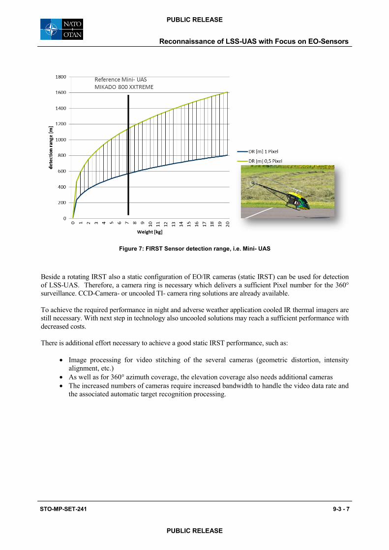
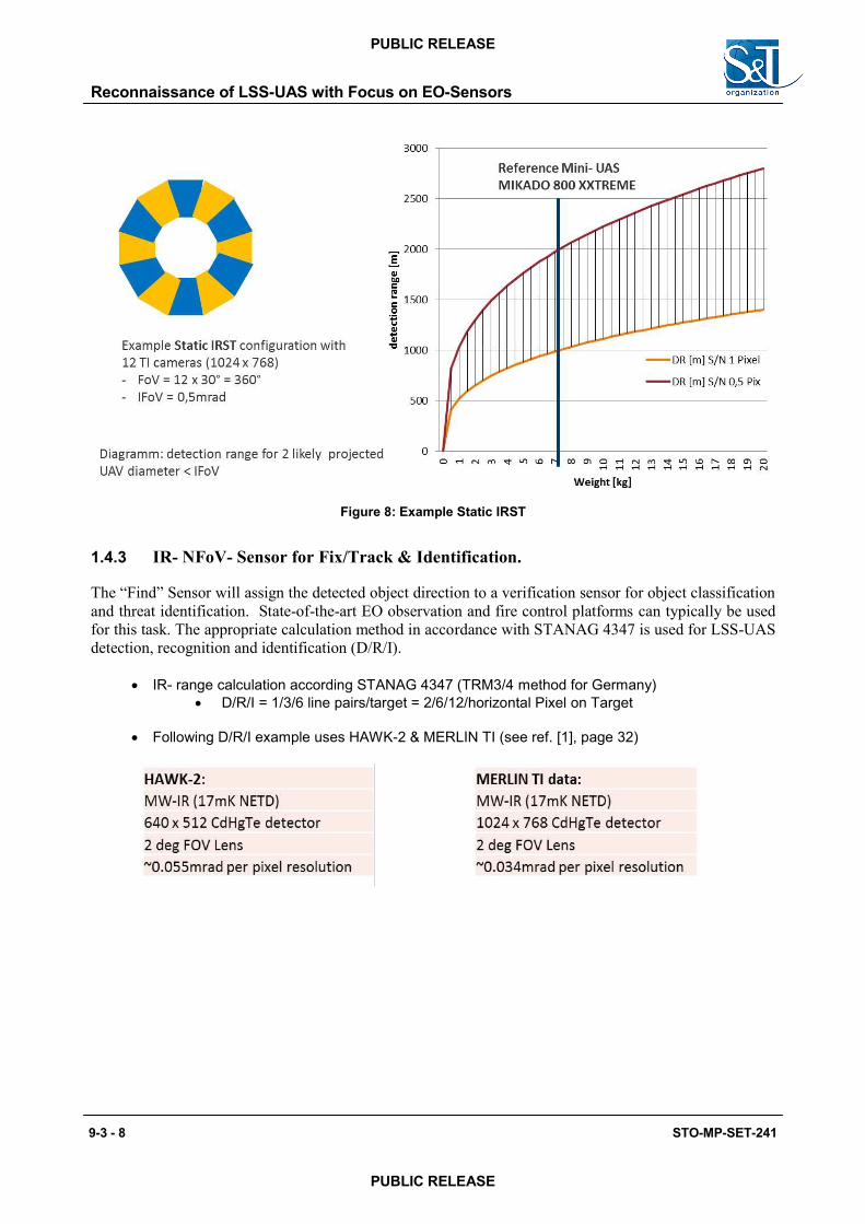
Figure 8: Example Static IRST
1.4.3 IR- NFoV- Sensor for Fix/Track & Identification.
The “Find” Sensor will assign the detected object direction to a verification sensor for object classification and threat identification. State-of-the-art EO observation and fire control platforms can typically be used for this task. The appropriate calculation method in accordance with STANAG 4347 is used for LSS-UAS detection, recognition and identification (D/R/I).
IR- range calculation according STANAG 4347 (TRM3/4 method for Germany) D/R/I = 1/3/6 line pairs/target = 2/6/12/horizontal Pixel on Target
Following D/R/I example uses HAWK-2 & MERLIN TI (see ref. [1], page 32)
Reconnaissance of LSS-UAS with Focus on EO-Sensors
9-3 - 8 STO-MP-SET-241
PUBLIC RELEASE
PUBLIC RELEASE
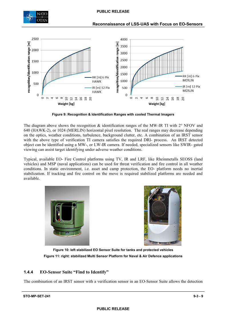
Figure 9: Recognition & Identification Ranges with cooled Thermal Imagers
The diagram above shows the recognition & identification ranges of the MW-IR TI with 2° NFOV and 640 (HAWK-2), or 1024 (MERLIN) horizontal pixel resolution. The real ranges may decrease depending on the optics, weather conditions, turbulence, background clutter, etc. A combination of an IRST sensor with the above type of verification TI camera satisfies the required DRI- process. An IRST detected object can be identified using a MW-, or LW-IR camera. If needed, specialized sensors like SWIR- gated viewing can assist target identifying under adverse weather conditions.
Typical, available EO- Fire Control platforms using TV, IR and LRF, like Rheinmetalls SEOSS (land vehicles) and MSP (naval applications) can be used for threat verification and fire control in all weather conditions. In static environment, i.e. asset and camp protection, the EO- platform needs no inertial stabilization. If tracking and fire control on the move is required stabilized platforms are needed and available.
Figure 10: left stabilized EO Sensor Suite for tanks and protected vehicles
Figure 11: right: stabilized Multi Sensor Platform for Naval & Air Defence applications
1.4.4 EO-Sensor Suite “Find to Identify”
The combination of an IRST sensor with a verification sensor in an EO-Sensor Suite allows the detection
Reconnaissance of LSS-UAS with Focus on EO-Sensors
STO-MP-SET-241 9-3 - 9
PUBLIC RELEASE
PUBLIC RELEASE
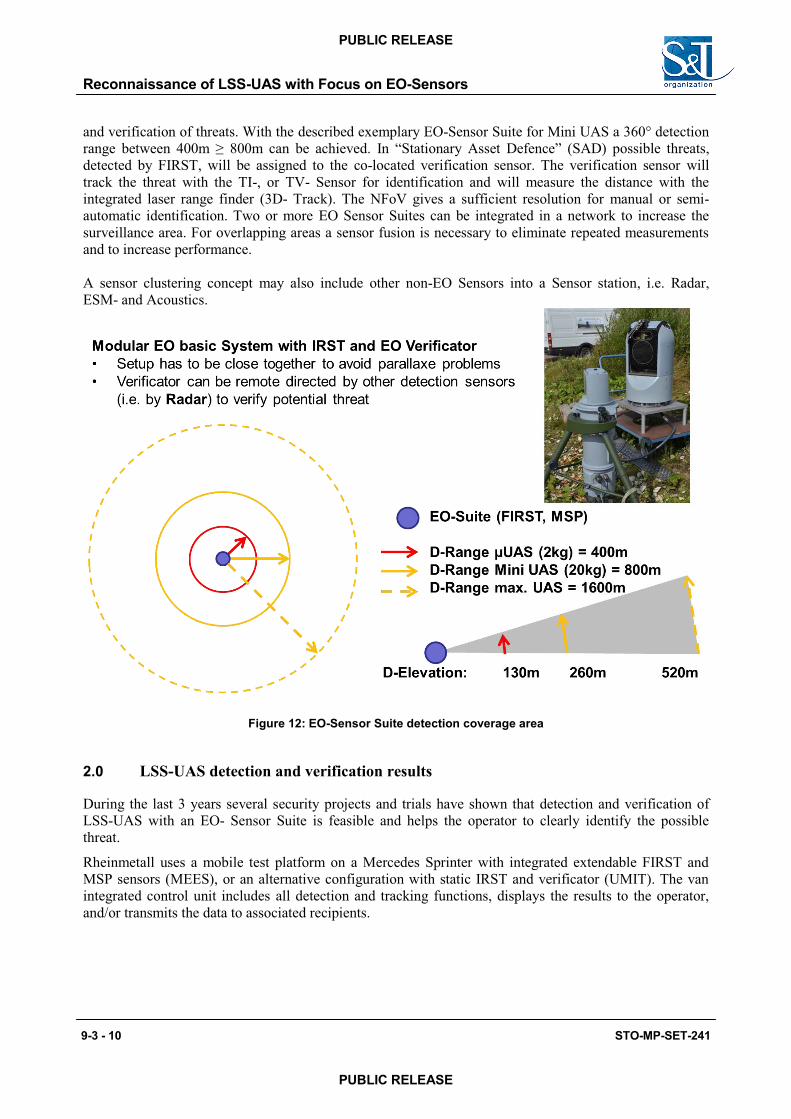
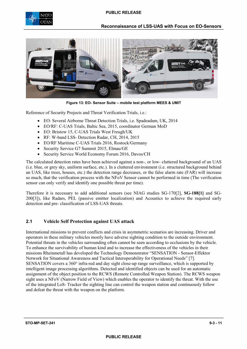
Figure 13: EO- Sensor Suite – mobile test platform MEES & UMIT
Reference of Security Projects and Threat Verification Trials, i.e.:
EO: Several Airborne Threat Detection Trials, i.e. Spadeadam, UK, 2014 EO/RF: C-UAS Trials, Baltic Sea, 2015, coordinator German MoD EO: Bristow 15, C-UAS Trials West Freugh/UK RF: W-band LSS- Detection Radar, CH, 2014, 2015 EO/RF Maritime C-UAS Trials 2016, Rostock/Germany Security Service G7 Summit 2015, Elmau/GE Security Service World Economy Forum 2016, Davos/CH
The calculated detection rates have been achieved against a non-, or low- cluttered background of an UAS (i.e. blue, or grey sky, uniform surface, etc.). In a cluttered environment (i.e. structured background behind an UAS, like trees, houses, etc.) the detection range decreases, or the false alarm rate (FAR) will increase so much, that the verification process with the NFoV Sensor cannot be performed in time (The verification sensor can only verify and identify one possible threat per time).
Therefore it is necessary to add additional sensors (see NIAG studies SG-170[2], SG-188[1] and SG-200[3]), like Radars, PEL (passive emitter localization) and Acoustics to achieve the required early detection and pre- classification of LSS-UAS threats.
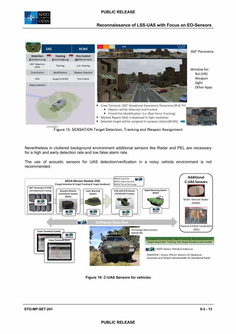
2.1 Vehicle Self Protection against UAS attack
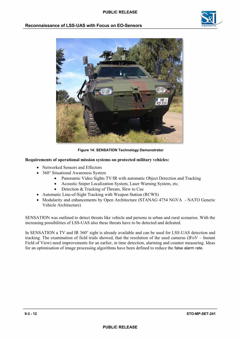
International missions to prevent conflicts and crisis in asymmetric scenarios are increasing. Driver and operators in these military vehicles mostly have adverse sighting condition to the outside environment. Potential threats in the vehicles surrounding often cannot be seen according to occlusions by the vehicle. To enhance the survivability of human kind and to increase the effectiveness of the vehicles in their missions Rheinmetall has developed the Technology Demonstrator “SENSATION - Sensor-Effektor Network for Situational Awareness and Tactical Interoperability for Operational Needs” [7]. SENSATION covers a 360° infra-red and day sight close-up range surveillance, which is supported by intelligent image processing algorithms. Detected and identified objects can be used for an automatic assignment of the object position to the RCWS (Remote Controlled Weapon Station). The RCWS weapon sight uses a NFoV (Narrow Field of View) which enables the operator to identify the threat. With the use of the integrated LoS- Tracker the sighting line can control the weapon station and continuously follow and defeat the threat with the weapon on the platform.
Reconnaissance of LSS-UAS with Focus on EO-Sensors
STO-MP-SET-241 9-3 - 11
PUBLIC RELEASE
PUBLIC RELEASE
2.2 Sensor Data Fusion For C-UAS tasks mostly a sensor combination is necessary for a sufficient detection- and low false alarm- rate. Data from multiple sensors of the same type, or different types have to be combined, or fused. Main tasks for sensor data fusion are listed below.
Sensor Data Fusion of multiple identical sensors on a vehicle:
Combination of sector sensors (i.e. 90° AZ Radar) to a consolidated 360° view Fusion of multiple detections of the same object caused by sector overlap Continuously object tracking in overlapping sensor sectors.
Enhancement of detection probability and reduction of false alarm rate (FAR) Sensor data assessment and weighted fusion of different sensor types Fusion of features from different sensors to increase classification results (Radio
pattern, RCS, µ-Doppler, EO, etc.)
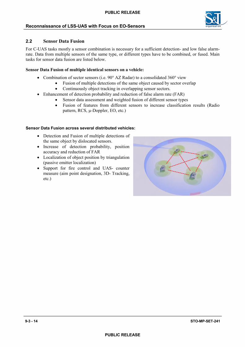
Sensor Data Fusion across several distributed vehicles:
Detection and Fusion of multiple detections ofthe same object by dislocated sensors.
Increase of detection probability, positionaccuracy and reduction of FAR
Localization of object position by triangulation(passive emitter localization)
Support for fire control and UAS- countermeasure (aim point designation, 3D- Tracking,etc.)
Reconnaissance of LSS-UAS with Focus on EO-Sensors
9-3 - 14 STO-MP-SET-241
PUBLIC RELEASE
PUBLIC RELEASE
2.3 C-UAS self defence for vehicles
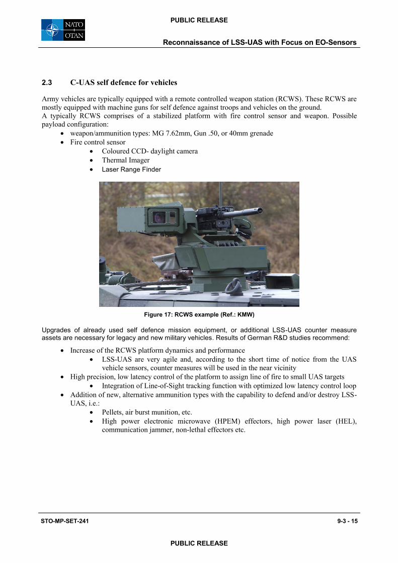
Army vehicles are typically equipped with a remote controlled weapon station (RCWS). These RCWS are mostly equipped with machine guns for self defence against troops and vehicles on the ground. A typically RCWS comprises of a stabilized platform with fire control sensor and weapon. Possible payload configuration:
weapon/ammunition types: MG 7.62mm, Gun .50, or 40mm grenade Fire control sensor
Coloured CCD- daylight camera Thermal Imager Laser Range Finder
Figure 17: RCWS example (Ref.: KMW)
Upgrades of already used self defence mission equipment, or additional LSS-UAS counter measure assets are necessary for legacy and new military vehicles. Results of German R&D studies recommend:
Increase of the RCWS platform dynamics and performance LSS-UAS are very agile and, according to the short time of notice from the UAS
vehicle sensors, counter measures will be used in the near vicinity High precision, low latency control of the platform to assign line of fire to small UAS targets
Integration of Line-of-Sight tracking function with optimized low latency control loop Addition of new, alternative ammunition types with the capability to defend and/or destroy LSS-
UAS, i.e.: Pellets, air burst munition, etc. High power electronic microwave (HPEM) effectors, high power laser (HEL),
communication jammer, non-lethal effectors etc.
Reconnaissance of LSS-UAS with Focus on EO-Sensors
STO-MP-SET-241 9-3 - 15
PUBLIC RELEASE
PUBLIC RELEASE
2.4 Recommendation for stationary and mobile Counter- UAS
General Recommendation for reliable detection and alerting of LSS-UAS:
Sensor- Cluster with application specific selected active and passive sensors, including sensordata fusion
Communication network between deployed sensor- clusters for stationary, or mobile application
C-UAS Recommendations regarding Mobile Force Protection (MFP):
Incorporation of Size, Weight, Power and Costs (SWaPC) for additional or modified C-UASSensors and Equipment for autonomous protection of vehicles.
Improvements (C-UAS upgrade) of already available mission sensors and effectorsare preferred versus costly enlargement of mission equipment.
MFP system shall consist of a combination of Sensors, like active Radars, EO- Sensors andpassive emitter localization (PEL-FPV), with successive Sensor Data Fusion
A Network between mobile platforms (vehicle) increases the LSS-UAS localization bytriangulation of UAS- bearing and sensor data fusion from distributed platforms
A connection to the „local air picture“(blue force tracking) for protection of own flying assets(UAS).
2.5 Summary and Perspective
IRST Sensors are suitable for 360° detection, tracking and alerting of LSS-UAS. In Combination with other sensor types (Radar, ESM, acoustics, etc.) efficient sensor cluster can
be configured (see NIAG SG-188). Already mounted sensors and effectors on vehicles for self-defence are not appropriate for
counter LSS-UAS tasks and have to be upgraded or extended. Size, Weight Power and Costs (SWaPC) have to be considered for mobile force
protection. Modular, NGVA (STANAG 4754) compliant vehicle mission systems provide easy extension
possibilities to integrate necessary C-UAS functions. Network and Fusion of sensors on a platform, or on distributed platforms are required for a high
detection probability with low false alarm rate. Verification, identification and also fire control of LSS-UAS threats need a remote controlled,
agile EO- platform with high resolution field of view and image processing assistance. For early detection convenient smart sensors with increased performance and enhanced image
processing algorithms are still required.
Reconnaissance of LSS-UAS with Focus on EO-Sensors
9-3 - 16 STO-MP-SET-241
PUBLIC RELEASE
PUBLIC RELEASE
REFERENCES
[1] NIAG SG-188: FINAL REPORT OF NIAG SG-188 STUDY ON GBAD SENSOR MIX OPTIMISATION STUDY FOR EMERGING THREATS
[2] NIAG SG-170: FINAL REPORT OF NIAG SG170 ON ENGAGEMENT OF LOW, SLOW AND SMALLAERIAL TARGETS BY GBAD, 16th September 2013
[3] NIAG SG-200: FINAL REPORT OF NIAG SG-200 STUDY ON LOW, SLOW AND SMALL THREAT EFFECTORS, draft – will be available August 2017
[4] DARPA-PS-17-01: PROGRAM SOLICITATION DARPA-PS-17-01 for MOBILE FORCE PROTECTION OCTOBER 26, 2016.
[5] LSS-ZZW, F&T- Studie LSS-UAV- Aufklärung in NGVA-ZZW, Rheinmetall Defence Electronics R&T Study for BAAINBw, 2015
[6] R&D Counter-UAS Study, F&T Studie Counter-UAS, 2016 – 2019, BAAINBw, Status Report 2016
[7] SENSATION, Final Report BL 8445 T016 TB, 05.12.2014, Optimierung der Sensorsuite ZZW SENSATION
Reconnaissance of LSS-UAS with Focus on EO-Sensors
STO-MP-SET-241 9-3 - 17
PUBLIC RELEASE
PUBLIC RELEASE
Reconnaissance of LSS-UAS with Focus on EO-Sensors
9-3 - 18 STO-MP-SET-241
PUBLIC RELEASE
PUBLIC RELEASE