Embed Size (px)
Citation preview
IRC:11-2015
Recommended pRactice foR the design and layout of cycle tRacKs
(First Revision)
Published by:
indian Roads congRessKama Koti Marg,
Sector-6, R.K. Puram, New Delhi-110 022
January, 2015
Price : ` 400/-
(Plus Packing & Postage)
IRC:11-2015
First Published : June, 1999First Revision : January, 2015
(All Rights Reserved. No part of this publication shall be reproduced, translated or transmitted in any form or by any means without the
permission of the Indian Roads Congress)
Printed by India Offset Press, Delhi-110064
1000 Copies
IRC:11-2015
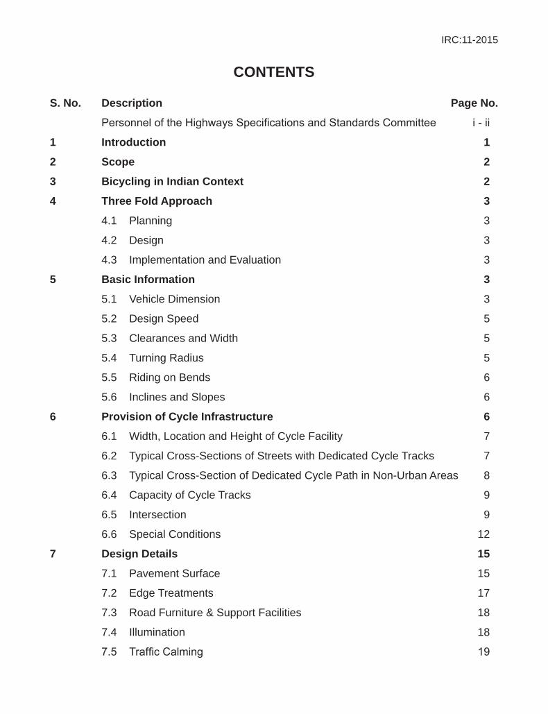
contents
s. no. description page no.
PersonneloftheHighwaysSpecificationsandStandardsCommittee i-ii
1 introduction 1
2 scope 2
3 Bicycling in indian context 2
4 three fold approach 3
4.1 Planning 3
4.2 Design 3
4.3 Implementation and Evaluation 3
5 Basic information 3
5.1 Vehicle Dimension 3
5.2 Design Speed 5
5.3 Clearances and Width 5
5.4 Turning Radius 5
5.5 Riding on Bends 6
5.6 Inclines and Slopes 6
6 provision of cycle infrastructure 6
6.1 Width, Location and Height of Cycle Facility 7
6.2 Typical Cross-Sections of Streets with Dedicated Cycle Tracks 7
6.3 Typical Cross-Section of Dedicated Cycle Path in Non-Urban Areas 8
6.4 Capacity of Cycle Tracks 9
6.5 Intersection 9
6.6 Special Conditions 12
7 design details 15
7.1 Pavement Surface 15
7.2 Edge Treatments 17
7.3 Road Furniture & Support Facilities 18
7.4 Illumination 18
7.5 TrafficCalming 19
IRC:11-2015
7.6 Signage & Marking 20
7.7 Services & Utilities 21
8 Bicycle parking 229 design elements 24 9.1 Horizontal Curves 24
9.2 Stopping Sight Distance 25
9.3 Vertical Curves 26
9.4 Cross Section Design 26
9.5 Intersection Design 29
9.6 Signage 33
9.7 Marking 34
10 References 34
IRC:11-2015
i
peRsonnel of the highways specifications and standaRds committee
(as on 9th august, 2014)
1. Das, S.N. Director General (Road Development), Ministry of Road (Convenor) Transport & Highways, New Delhi.
2. Varkeyachan, K.C. Addl. Director General, Ministry of Road (Co-Convenor) Transport & Highways, New Delhi.
3. Chief Engineer (R) S,R&T (Rep. by Shri S.K. Nirmal), Ministry of Road (Member-Secretary) Transport & Highways, New Delhi
Members
4. Basu, S.B. Chief Engineer (Retd.), MORTH, New Delhi
5. Bongirwar, P.L. Advisor, L & T, Mumbai
6. Bose, Dr. Sunil Head FPC Divn. CRRI (Retd.), Faridabad
7. Duhsaka, Vanlal Chief Engineer, PWD (Highways), Aizwal (Mizoram)
8. Gangopadhyay, Dr. S. Director, Central Road Research Institute, New Delhi
9. Gupta, D.P. Director General (RD) & AS (Retd.), MORTH, New Delhi
10. Jain, R.K. Chief Engineer (Retd.), Haryana PWD, Sonipat
11. Jain, N.S. Chief Engineer (Retd.), MORTH, New Delhi
12. Jain, Dr. S.S. Professor & Coordinator, Centre of Transportation Engg., Dept. of Civil Engg., IIT Roorke, Roorkee
13. Kadiyali, Dr. L.R. Chief Executive, L.R. Kadiyali & Associates, New Delhi
14. Kumar, Ashok Chief Engineer (Retd.), MORTH, New Delhi
15. Kurian, Jose Chief Engineer, DTTDC Ltd., New Delhi
16. Kumar, Mahesh Engineer-in-Chief, Haryana PWD, Chandigarh
17. Kumar, Satander Ex-Scientist, CRRI, New Delhi
18. Lal, Chaman Director (Projects-III), NRRDA (Ministry of Rural Development), New Delhi
19. Manchanda, R.K. Consultant, Intercontinental Consultants and Technocrats Pvt. Ltd., New Delhi
20. Marwah, S.K. Addl. Director General (Retd.), MORTH, New Delhi
21. Pandey, R.K. Chief Engineer (Planning), MORTH, New Delhi
22. Pateriya, Dr. I.K. Director (Tech.), NRRDA, (Ministry of Rural Development), New Delhi
23. Pradhan, B.C. Chief Engineer, National Highways, Bhubaneshwar
24. Prasad, D.N. Chief Engineer (NH), RCD, Patna
25. Rao, P.J. Consulting Engineer, H.No. 399, Sector-19, Faridabad
IRC:11-2015
ii
26. Raju, G.V.S. Dr. Engineer-in-Chief (R&B), Rural Roads, Director Research and Consultancy, Hyderabad, Andhra Pradesh
27. Representative of BRO (Shri B.B. Lal) ADGBR, HQ DGBR, New Delhi
28. Sarkar, Dr. P.K. Professor, Deptt. of Transport Planning, School of Planning & Architecture, New Delhi
29. Sharma, Arun Kumar CEO (Highways), GMR Highways Limited, Bangalore
30. Sharma, M.P. Member (Technical), NHAI, New Delhi
31. Sharma, S.C. DG (RD) & AS (Retd.), MORTH, New Delhi
32. Sinha, A.V. DG (RD) & SS (Retd.), MORTH, New Delhi
33. Singh, B.N. Member (Projects), NHAI, New Delhi
34. Singh, Nirmal Jit DG (RD) & SS (Retd.), MORTH, New Delhi
35. Vasava, S.B. Chief Engineer & Addl. Secretary (Panchayat) Roads & Building Dept., Gandhinagar
36. Yadav, Dr. V.K. Addl. Director General (Retd.), DGBR, New Delhi
37. The Chief Engineer (Mech.) (Shri Kaushik Basu), MORTH, New Delhi
Corresponding Members
1. Bhattacharya, C.C. DG (RD) & AS (Retd.), MORTH, New Delhi
2. Das, Dr. Animesh Professor, IIT, Kanpur
3. Justo, Dr. C.E.G. Emeritus Fellow, 334, 14th Main, 25th Cross, Banashankari 2nd Stage, Bangalore
4. Momin, S.S. Former Secretary, PWD Maharashtra, Mumbai
5. Pandey, Prof. B.B. Advisor, IIT Kharagpur, Kharagpur
Ex-Officio Members
1. President, (Bhowmik, Sunil), Engineer-in-Chief, Indian Roads Congress PWD (R&B), Govt. of Tripura
2. Honorary Treasurer, (Das, S.N.), Director General (Road Development), Indian Roads Congress Ministry of Road Transport & Highways
3. Secretary General, Indian Roads Congress
IRC:11-2015
1
Recommended pRactice foR the design and layout of cycle tRacKs
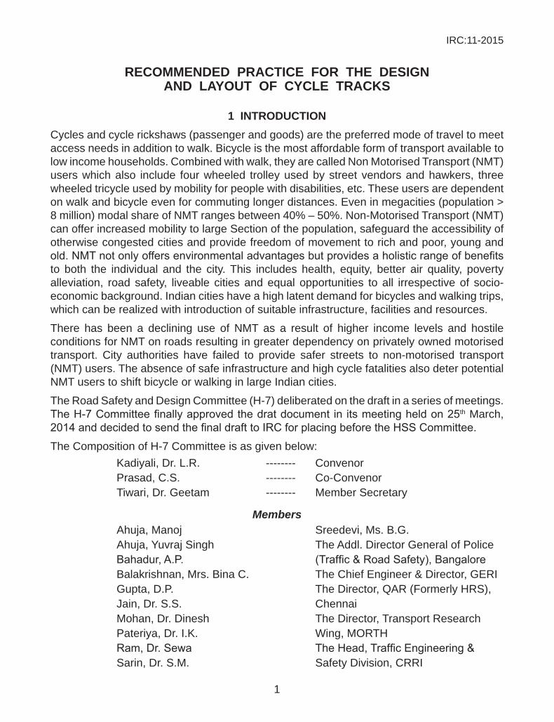
1 intRoductionCycles and cycle rickshaws (passenger and goods) are the preferred mode of travel to meet access needs in addition to walk. Bicycle is the most affordable form of transport available to low income households. Combined with walk, they are called Non Motorised Transport (NMT) users which also include four wheeled trolley used by street vendors and hawkers, three wheeled tricycle used by mobility for people with disabilities, etc. These users are dependent on walk and bicycle even for commuting longer distances. Even in megacities (population > 8 million) modal share of NMT ranges between 40% – 50%. Non-Motorised Transport (NMT) can offer increased mobility to large Section of the population, safeguard the accessibility of otherwise congested cities and provide freedom of movement to rich and poor, young and old.NMTnotonlyoffersenvironmentaladvantagesbutprovidesaholisticrangeofbenefitsto both the individual and the city. This includes health, equity, better air quality, poverty alleviation, road safety, liveable cities and equal opportunities to all irrespective of socio-economic background. Indian cities have a high latent demand for bicycles and walking trips, which can be realized with introduction of suitable infrastructure, facilities and resources.
There has been a declining use of NMT as a result of higher income levels and hostile conditions for NMT on roads resulting in greater dependency on privately owned motorised transport. City authorities have failed to provide safer streets to non-motorised transport (NMT) users. The absence of safe infrastructure and high cycle fatalities also deter potential NMT users to shift bicycle or walking in large Indian cities.
The Road Safety and Design Committee (H-7) deliberated on the draft in a series of meetings. TheH-7Committeefinallyapprovedthedratdocument in itsmeetingheldon25th March, 2014anddecidedtosendthefinaldrafttoIRCforplacingbeforetheHSSCommittee.
The Composition of H-7 Committee is as given below: Kadiyali, Dr. L.R. -------- Convenor Prasad, C.S. -------- Co-Convenor Tiwari, Dr. Geetam -------- Member Secretary
Members Ahuja, Manoj Sreedevi, Ms. B.G. Ahuja, Yuvraj Singh The Addl. Director General of Police Bahadur,A.P. (Traffic&RoadSafety),Bangalore Balakrishnan, Mrs. Bina C. The Chief Engineer & Director, GERI Gupta, D.P. The Director, QAR (Formerly HRS), Jain, Dr. S.S. Chennai Mohan, Dr. Dinesh The Director, Transport Research Pateriya, Dr. I.K. Wing, MORTH Ram,Dr.Sewa TheHead,TrafficEngineering& Sarin, Dr. S.M. Safety Division, CRRI
IRC:11-2015
2
Shankar, Dr. Ravi The Joint Commissioner of Police, Sharma,S.C. Traffic,Delhi Sikdar, Prof. P.K. The C.E.(R), S&R, MORTH
Singh, Amarjit
Ex-Officio Members President, (Bhowmik, Sunil), Engineer-in-Chief, Indian Roads Congress PWD (R&B), Govt. of Tripura Honorary Treasurer, (Das, S.N.) Director General Indian Roads Congress (Road Development), Ministry of Road Transport & Highways Secretary General, Indian Roads CongressTheHighwaysSpecifications&StandardsCommittee(HSS)approvedthedraftdocumentin its meeting held on 9th August, 2014. The Executive Committee in its meeting held on 18th August, 2014 approved the same document for placing it before the Council. The IRC Council in its 203rd meeting held at New Delhi on 19th and 20th August, 2014 approved the draft IRC:11-2015 “Recommended Practice for the Design and Layout of Cycle Tracks” (First Revision) for publishing.
2 scope
The present guidelines provide a comprehensive overview to make cycle friendly infrastructure in cities. Guidance is given for rural roads also.
3 Bicycling in indian conteXt
Bicycleisforall.Itisusedbyallagegroupsandgender.NMTuserscanalsobeclassifiedinto two categories – one who bicycles by choice and the second who is a ‘captive cyclist’ who is bound by economic constraints and does not have a choice. Indian Cities are dominated by the latter. The presence of an infrastructure will encourage choice and recreational use. High ownership of bicycles, low cost and easy use make it a desirable mode of transport for students and low income workers. The absolute number of cyclists rise to a million that account to about 6-8 percent of modal share in mega cities. Regardless of city size many Indian cities have 80 percent of the trips shorter than 3 km and about 70 percent less than 10 km (Jain, 2013). These trips are ideal for non-motorized modes like bicycles.
From the point of sustainability and preservation of the environment, India has to take steps to maketravelbycyclesmoreattractive.Thebenefitsofcyclingarewellknown.Thepromotionof active transport (cycling and walking) for everyday physical activity is a win-win approach; it not only promotes health but can also lead to positive environmental effects, especially if cycling and walking replace short car trips. (HEAT- Health Economic Assessment Tool for walking and cycling ((WHO), 2011)) Cycling and walking can also be more readily integrated into people’s busy schedules than, for example, leisure-time exercise. Also, In Indian cities, 50 - 80% of the road related injuries are to the pedestrians and cyclists though the status had been similar since late 1980s. Bicycles generate no noise pollution and emissions. A better
IRC:11-2015
3
bicycle infrastructure can play an important role in increasing the modal share of bicycles, reducing air pollution and reducing the adverse health effects of pollution.
4 thRee fold appRoach
4.1 planningA NMT master Plan and a network plan highlight the issues of cohesion and directness, attractiveness and comfort and safety and security, the three founding principles in planning a bicycle infrastructure. These objectives can be met only when cyclists have a network of usable links which can take them from end to end. The NMT Master Plan should set the goals anddesiredlevelofserviceforbicyclefriendlyinfrastructureandincludequantifiablecriteriasuch as average cycling speeds, capacity (at a desired level of service - LOS), parking infrastructure (frequency and capacity along the route), integration options with public transport (parking infrastructure, fare concessions, feeder infrastructure,) etc.
4.2 designInfrastructure design should be based upon the road hierarchy in the network and the identificationofthecorridor.Aspartofdatacollectionitisimportanttocollectaccuratetotalstationsurveys,activitysurveysandtrafficvolumeandparkingcount.Accidentdatawillhelpthedesignertounderstandtheblackspotsanddangerousareasinthecorridoridentified.It involves preparation of geometric alignment based upon road typology and intersection needs.Thefivebasicprinciplesfordesignarecoherence,directness,safetyandsecurity,attractiveness and comfort. They are important to make any infrastructure bicycle friendly. Further detailing of the infrastructure is also required. This includes the choice of surface material, signage, marking, street furniture as well as location of bicycle parking and other support facilities like hawker spaces, etc.
4.3 implementation and evaluation The implementation phase includes detailed cost estimates based on the implementation drawings. Also, at the time of construction, safety of the workers as well as people passing throughthezoneneedstobegivenutmostimportance.IRC:SP:55:2013Guidelinesontrafficmanagementatworkzoneshighlightstheimportanceoftrafficmanagementandincludesinstructions and checklist required by project manager at site during construction. Another important aspect post construction is evaluation of a cycle facility, Auditing and Benchmarking are important to assess the performance of an individual bicycle facility at network as well as at city level.
5 Basic infoRmation
5.1 Vehicle dimensiontable 1 gives various dimensions.
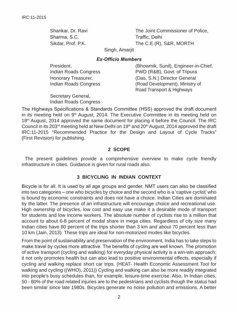
cycle: Bicycles are commonly used to carry gas cylinders, milk cans, etc. It is also commonly used for vending, and used for services such as post-delivery, telephone repair,
IRC:11-2015
4
garbage collection, etc. The bicycle is also used as retail platform to display and sell products, like toys, cooked food, tobacco products, etc. (fig. 1).
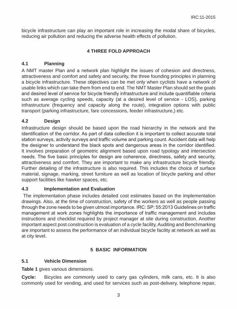
cycle Rickshaw: Cycle rickshaw is predominantly used as the main vehicle for commuting (mainly in small and medium sized cities) since the trips are short. (fig. 2).
good Rickshaw: Rickshaw is also used to transport goods to and from commercial shops. It is clear that even though in cities there are no visible passenger cycle rickshaw, good rickshaw are predominantly used for freight transport. The rickshaw needs to be the limiting design vehicle for the NMT infrastructure. (fig. 2).
tricycle for the differently abled: These are used by many physically challenged and mobility impaired for commuting from one place to the other.
a: length; b: height; c: width with rider; d: handle bar width; e: wheel size
Fig. 1 Basic Information-Bicycle
a: length; b: height; c: width with rider; d: handle bar width; e: wheel size
Fig. 2 Cycle Rickshaw - Passenger (L) goods (R)
table 1 Vehicle dimensions
a length (mm)
b hight (mm)
c width with Rider
(mm)
d handle Bar width
(mm)
e wheel size (dia.in
mm)Adult Touring Bike 1950 1200 750 600 710Adult Touring Bike with goods (milk cans or gas cylinders)
1950 1200 950 600 710
Passenger Rickshaw 2200 1200 1000 600 710Goods Rickshaw 2400 1200 1220 600 710Modifiedgoodsrickshaw 2600 1200 1400 600 710
IRC:11-2015
5
5.2 design speedThe average speed range of NMT is about 5 km/hr – 15 km/hr. In rare cases, it can be seen to be 20 km/hr. It is important for cyclists gain a cruising speed for constant usage. Interruptions due to parking, side roads, access to properties affect the desirable speed and makeitdifficultforthecyclist.Hence,variationsinalignment,levelsandformofthebicycleinfrastructure should be avoided. Vertical Gradients need to be well accommodated.
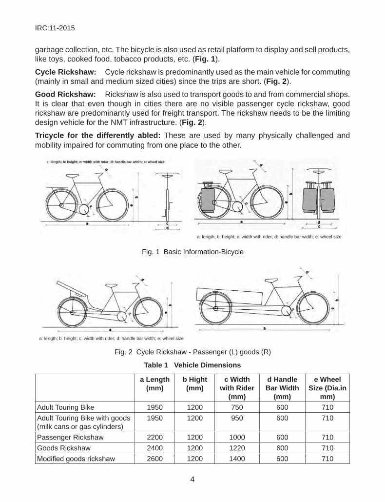
5.3 clearances and widthThe width requirement for a NMV in movement is higher than its physical dimensions. This is on account of two main factors, i.e. zigzagging movement (side to side movement to maintain balance during riding) and fear of obstacles (or maintenance of manoeuvring gap). Bicyclists carrying goods and pillion riders may experience higher zigzagging on account of extra weight carried, while cycle rickshaws experience minimal or no zigzagging. The distance that NMV maintain for fear of obstacles depends on the height of the obstacle. figure 3 shows us the variations in width and clearances from different obstacles.
Fig. 3 Clearances and Widths
total width (as per cycle type)
total clearance
from obstacles 0-50 mm
total clearance
from obstacles 50-150 mm
total clearance from obstacles Regarding
fixed objects like poles & Bollards in
mm
total clearance from fear of obstacles Regarding closed walls (from Body
edge) in mmw a b c d
Adult Touring Bike 750 0 125 325 625Adult Touring Bike with goods (milk cans or gas cylinders)
950 0 325 325 625
Passenger Rickshaw 1000 250 325 325 625Goods Rickshaw 1220 250 325 325 625Modifiedgoodsrickshaw
1400 250 325 325 625
5.4 turning RadiusBends are required for smooth connections between cycling path, and also to ensure continuity of the infrastructure. The radius of curves used in bending a path affects the speed of NMVs
IRC:11-2015
6
using it. Sharper the bend, lower the speed. Minimum design speed for stability requirement of a bicyclist is 12 km/hr. Bends of 30 m radius or more are preferred on segregated bicycle tracks to maintain visual directness and continuity of the path and also to reduce the path widening requirement due to additional width requirement for a rider negotiating bends. It is also evident that turning radius of less than 10 m should not be considered as it does not permit cycling at comfortable cruising speeds.
5.5 Riding on BendsAsafeleaningangleforacyclistwhilenegotiatingabendataco-efficientoffrictionof0.3,is about 18º from the vertical or 72º from the horizontal plane. A widening of about 0.51 m per lane is required to accommodate the extra width on account of this bending. At cruising speed, widening of cycle lanes become necessary for all turning radiuses less than 120 m (when the lean angle is negligible and widening requirement falls to less than 0.05 m per lane).
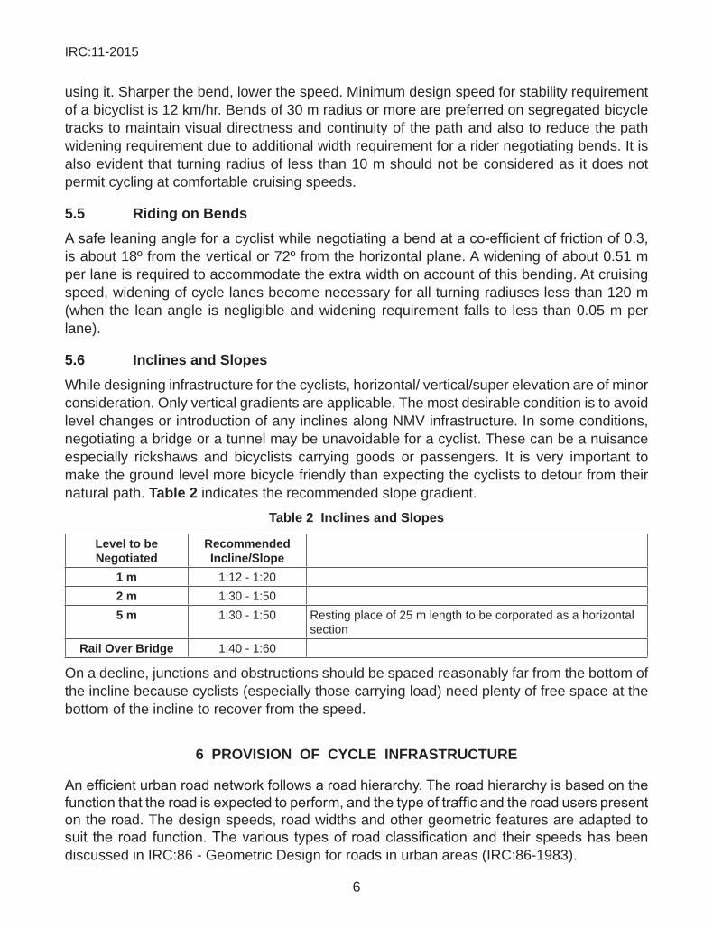
5.6 inclines and slopesWhile designing infrastructure for the cyclists, horizontal/ vertical/super elevation are of minor consideration. Only vertical gradients are applicable. The most desirable condition is to avoid level changes or introduction of any inclines along NMV infrastructure. In some conditions, negotiating a bridge or a tunnel may be unavoidable for a cyclist. These can be a nuisance especially rickshaws and bicyclists carrying goods or passengers. It is very important to make the ground level more bicycle friendly than expecting the cyclists to detour from their natural path. table 2 indicates the recommended slope gradient.
table 2 inclines and slopes
level to be negotiated
Recommended incline/slope
1 m 1:12 - 1:202 m 1:30 - 1:505 m 1:30 - 1:50 Resting place of 25 m length to be corporated as a horizontal
sectionRail over Bridge 1:40 - 1:60
On a decline, junctions and obstructions should be spaced reasonably far from the bottom of the incline because cyclists (especially those carrying load) need plenty of free space at the bottom of the incline to recover from the speed.
6 pRoVision of cycle infRastRuctuRe
Anefficienturbanroadnetworkfollowsaroadhierarchy.Theroadhierarchyisbasedonthefunctionthattheroadisexpectedtoperform,andthetypeoftrafficandtheroaduserspresenton the road. The design speeds, road widths and other geometric features are adapted to suit theroadfunction.Thevarioustypesofroadclassificationandtheirspeedshasbeendiscussed in IRC:86 - Geometric Design for roads in urban areas (IRC:86-1983).
IRC:11-2015
7
table 3 Road typology
Road typology Right of way-Row (m) design speed (km/hr)Arterial Roads 50-80 50 and aboveSub Arterial Roads 30-50 more than 30Distributor/Collector Roads 12-30 upto 30Access Streets 6-15 15
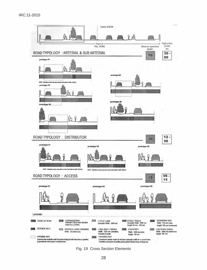
6.1 width, location and height of cycle facilityThe type of cycle facility therefore responds to the type of the road and the design speed (table 4). Various road design elements like the carriageway, pedestrian path etc have been discussed in section 8.4.
table 4 cycle infrastructure design for Various Road typology
arterial Roads sub arterial Roads distributory Roads access Roadscycle infRastRuctuRe
Segregated Cycle Track Segregated Cycle Track
Cycle Lane Mixed\traffic
location Between Carriageway or street parking and footpath on either edge of the carriageway
Between Carriageway or street parking and footpath on either edge of the carriageway
On the edge of the carriageway, adjacent to the footpath or parking.
gradient 1:12 – 1:20 (min) 1:12 – 1:20 (min) 1:12 – 1:20 (min) 1:12–1:20 (min)desirable lane width 2.5 to 5.0 m 2.5 to 5.0 m 1.5 to 2.5 m Mixed with
motorized vehiculartraffic
level +50 mm to +100 mm +50 mm to +100 mm 0.0 m 0.0 mminimum width 2.2 for a two lane cycle
track and 3 m to 4 m for a common cycle track and footpath (not more than a length of 40 m).
2.2 for a two lane cycle track and 3 m to 4 m for a common cycle track and footpath (not more than a length of 40 m).
1.2 m painted cycle lane Mixed condition
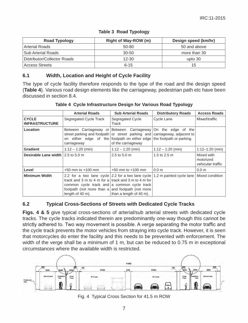
6.2 typical cross-sections of streets with dedicated cycle tracksfigs. 4 & 5 give typical cross-sections of arterial/sub arterial streets with dedicated cycle tracks. The cycle tracks indicated therein are predominantly one-way though this cannot be strictlyadheredto.Twowaymovementispossible.Avergeseparatingthemotortrafficandthe cycle track prevents the motor vehicles from straying into cycle track. However, it is seen that motorcycles do enter the facility and this needs to be prevented with enforcement. The width of the verge shall be a minimum of 1 m, but can be reduced to 0.75 m in exceptional circumstances where the available width is restricted.
Fig. 4 Typical Cross Section for 41.5 m ROW
IRC:11-2015
8
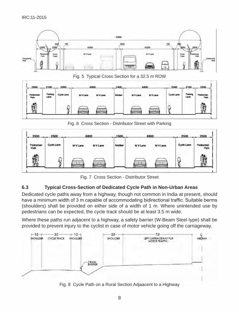
Fig. 5 Typical Cross Section for a 32.5 m ROW
Fig. 6 Cross Section - Distributor Street with Parking
Fig. 7 Cross Section - Distributor Street
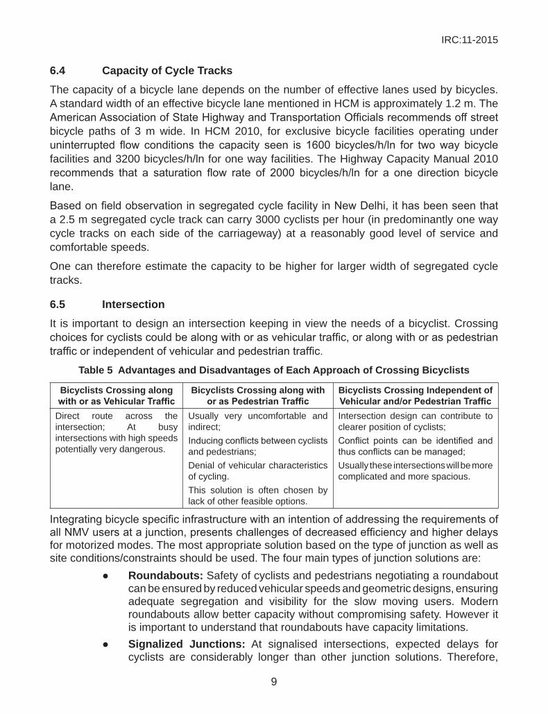
6.3 typical cross-section of dedicated cycle path in non-urban areasDedicated cycle paths away from a highway, though not common in India at present, should haveaminimumwidthof3mcapableofaccommodatingbidirectionaltraffic.Suitableberms(shoulders) shall be provided on either side of a width of 1 m. Where unintended use by pedestrians can be expected, the cycle track should be at least 3.5 m wide.
Where these paths run adjacent to a highway, a safety barrier (W-Beam Steel type) shall be provided to prevent injury to the cyclist in case of motor vehicle going off the carriageway.
Fig. 8 Cycle Path on a Rural Section Adjaacent to a Highway
IRC:11-2015
9
6.4 capacity of cycle tracksThe capacity of a bicycle lane depends on the number of effective lanes used by bicycles. A standard width of an effective bicycle lane mentioned in HCM is approximately 1.2 m. The AmericanAssociationofStateHighwayandTransportationOfficialsrecommendsoffstreetbicycle paths of 3 m wide. In HCM 2010, for exclusive bicycle facilities operating under uninterrupted flow conditions the capacity seen is 1600 bicycles/h/ln for twoway bicyclefacilities and 3200 bicycles/h/ln for one way facilities. The Highway Capacity Manual 2010 recommends that a saturation flow rate of 2000 bicycles/h/ln for a one direction bicyclelane.
BasedonfieldobservationinsegregatedcyclefacilityinNewDelhi,ithasbeenseenthata 2.5 m segregated cycle track can carry 3000 cyclists per hour (in predominantly one way cycle tracks on each side of the carriageway) at a reasonably good level of service and comfortable speeds.
One can therefore estimate the capacity to be higher for larger width of segregated cycle tracks.
6.5 intersectionIt is important to design an intersection keeping in view the needs of a bicyclist. Crossing choicesforcyclistscouldbealongwithorasvehiculartraffic,oralongwithoraspedestriantrafficorindependentofvehicularandpedestriantraffic.
table 5 advantages and disadvantages of each approach of crossing Bicyclists
Bicyclists crossing along with or as Vehicular Traffic
Bicyclists crossing along with or as Pedestrian Traffic
Bicyclists crossing independent of Vehicular and/or Pedestrian Traffic
Direct route across the intersection; At busy intersections with high speeds potentially very dangerous.
Usually very uncomfortable and indirect;Inducingconflictsbetweencyclistsand pedestrians;Denial of vehicular characteristics of cycling.This solution is often chosen by lack of other feasible options.
Intersection design can contribute to clearer position of cyclists;Conflict points can be identified andthusconflictscanbemanaged;Usually these intersections will be more complicated and more spacious.
IntegratingbicyclespecificinfrastructurewithanintentionofaddressingtherequirementsofallNMVusersatajunction,presentschallengesofdecreasedefficiencyandhigherdelaysfor motorized modes. The most appropriate solution based on the type of junction as well as site conditions/constraints should be used. The four main types of junction solutions are: ● Roundabouts: Safety of cyclists and pedestrians negotiating a roundabout
can be ensured by reduced vehicular speeds and geometric designs, ensuring adequate segregation and visibility for the slow moving users. Modern roundabouts allow better capacity without compromising safety. However it is important to understand that roundabouts have capacity limitations.
● signalized Junctions: At signalised intersections, expected delays for cyclists are considerably longer than other junction solutions. Therefore,
IRC:11-2015
10
aflexibleapproach toadaptasingleorcombinationofcrossingmethodsshould be adopted. In signalized intersection, the following is of importance –
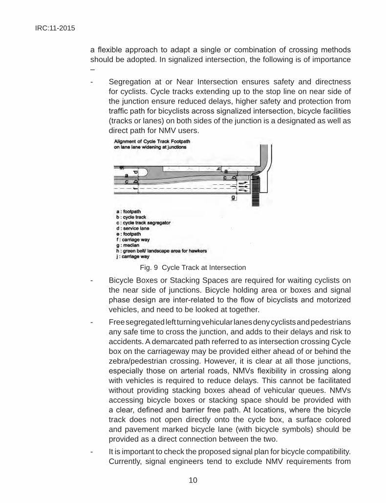
- Segregation at or Near Intersection ensures safety and directness for cyclists. Cycle tracks extending up to the stop line on near side of the junction ensure reduced delays, higher safety and protection from trafficpathforbicyclistsacrosssignalizedintersection,bicyclefacilities(tracks or lanes) on both sides of the junction is a designated as well as direct path for NMV users.
Fig. 9 Cycle Track at Intersection
- Bicycle Boxes or Stacking Spaces are required for waiting cyclists on the near side of junctions. Bicycle holding area or boxes and signal phasedesignare inter-relatedtotheflowofbicyclistsandmotorizedvehicles, and need to be looked at together.
- Free segregated left turning vehicular lanes deny cyclists and pedestrians any safe time to cross the junction, and adds to their delays and risk to accidents. A demarcated path referred to as intersection crossing Cycle box on the carriageway may be provided either ahead of or behind the zebra/pedestrian crossing. However, it is clear at all those junctions, especially those on arterial roads,NMVs flexibility in crossing alongwith vehicles is required to reduce delays. This cannot be facilitated without providing stacking boxes ahead of vehicular queues. NMVs accessing bicycle boxes or stacking space should be provided with aclear,definedandbarrierfreepath.At locations,wherethebicycletrack does not open directly onto the cycle box, a surface colored and pavement marked bicycle lane (with bicycle symbols) should be provided as a direct connection between the two.
- It is important to check the proposed signal plan for bicycle compatibility. Currently, signal engineers tend to exclude NMV requirements from
IRC:11-2015
11
design considerations leading to inefficient and unsafe designs forcyclists. A separate signal phase might not be required.
● Traffic Calmed and Un-signalized Junctions: For minor intersections, it isrecommendedtoapplytrafficcalmingsuchasminiroundabouts,speedhumps, table tops to keep the speed of motor vehicles at check.
● grade separated crossing: Grade separated infrastructure should address all requirements of both current and potential cyclists. In some situations, this approach may require provision of both, at grade and grade separated crossing facilities to address different requirement for various NMV users. Grade separation of intersecting motorized vehicle carriageway is a high cost intersection design solution, which may be suitable for use on highways or expressways. Such solutions are not desirable within the built up areas or urban limit due to their adverse impact on accidents, pollution, etc. However, additionalgradeseparationofNMVandpedestriantrafficacrosshigh-speedhigh volume motorized vehicle carriageway may often be advisable to ensure safety of cyclists and pedestrians.
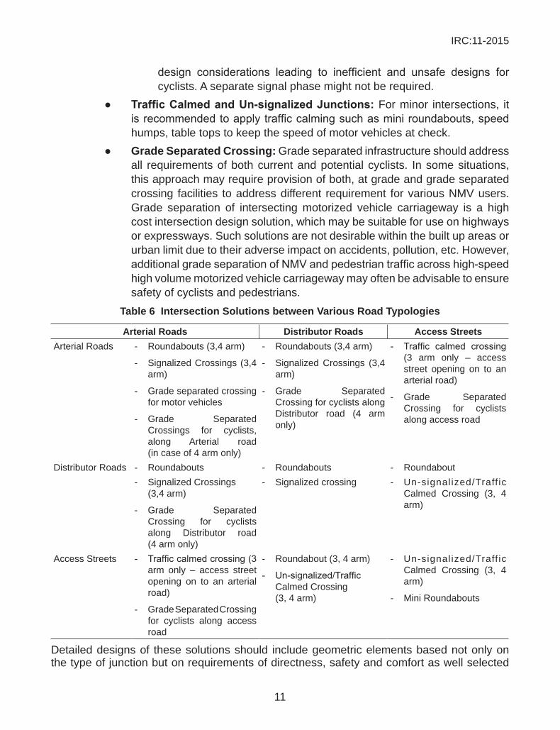
table 6 intersection solutions between Various Road typologies
arterial Roads distributor Roads access streetsArterial Roads - Roundabouts (3,4 arm)
- Signalized Crossings (3,4 arm)
- Grade separated crossing for motor vehicles
- Grade Separated Crossings for cyclists, along Arterial road (in case of 4 arm only)
- Roundabouts (3,4 arm)
- Signalized Crossings (3,4 arm)
- Grade Separated Crossing for cyclists along Distributor road (4 arm only)
- Traffic calmed crossing(3 arm only – access street opening on to an arterial road)
- Grade Separated Crossing for cyclists along access road
Distributor Roads - Roundabouts - Roundabouts - Roundabout- Signalized Crossings
(3,4 arm)
- Grade Separated Crossing for cyclists along Distributor road (4 arm only)
- Signalized crossing - Un-signal ized/Traff ic Calmed Crossing (3, 4 arm)
Access Streets - Trafficcalmedcrossing(3arm only – access street opening on to an arterial road)
- Grade Separated Crossing for cyclists along access road
- Roundabout (3, 4 arm)
- Un-signalized/TrafficCalmed Crossing (3, 4 arm)
- Un-signal ized/Traff ic Calmed Crossing (3, 4 arm)
- Mini Roundabouts
Detailed designs of these solutions should include geometric elements based not only on the type of junction but on requirements of directness, safety and comfort as well selected
IRC:11-2015
12
crossingmethodforcyclists.Section8.5showssomedesignconfigurationsasmentionedabove.
6.6 special conditionsWhilecrosssectionandintersectiondesignsprovidelocationspecificsolutions,theycannotbe completely used for implementation and development of a bicycle infrastructure on a corridor. This section discusses the alignment, layout and integration of various conditions andsituationswhichareseenonroads, inaplanandprofiledrawingfor implementation.To comply with the principles of bicycle infrastructure, the following should to be taken into consideration: ● Location of NMV/Bicycle Path/Lane in the Cross Section ● Width of bicycle path/lane ● form of bicycle path/lane: Bicycle lanes require less width than segregated
bicycle tracks. Bicycle lanes may be introduced for the length of a stretch constrained by available space where there is an existing track.
● function of bicycle path/lane: Compromises affecting the function of bicycle path/lane include combining or sharing of bicycle infrastructure with other users or functions such as pedestrian path in case of NMV/Bicycle tracks and carriageway in case of NMV/Bicycle lanes. These compromises should only be made where continuous length of constriction/limitation is between 5 and 40 m.
The special conditions seen are as follows:
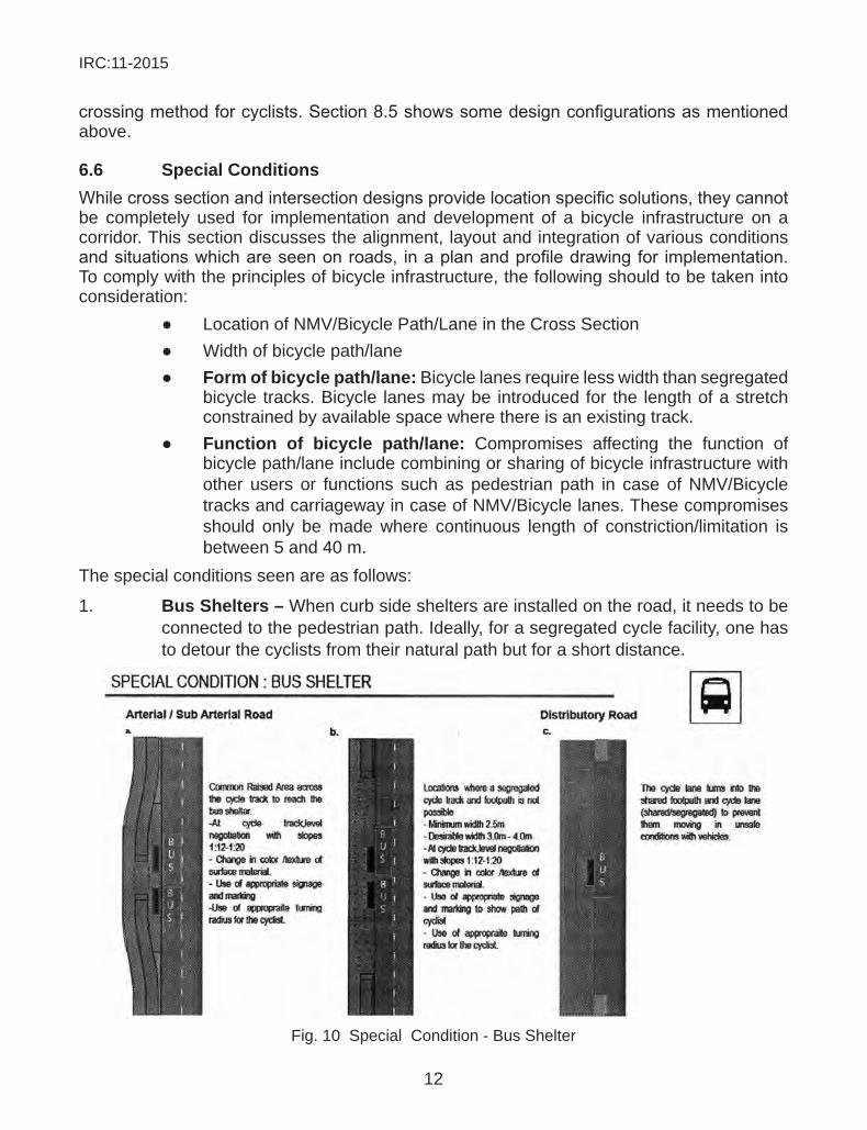
1. Bus shelters – When curb side shelters are installed on the road, it needs to be connected to the pedestrian path. Ideally, for a segregated cycle facility, one has to detour the cyclists from their natural path but for a short distance.
Fig. 10 Special Condition - Bus Shelter
IRC:11-2015
13
2. hawker spaces – Presence of hawkers and street vendors provides security and services to road commuters. Allocation of a dedicated space shall also make the street more lively and interesting.
Fig. 11 Special Condition - Hawker Space
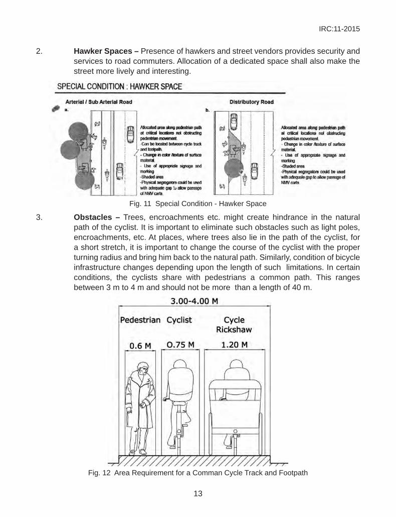
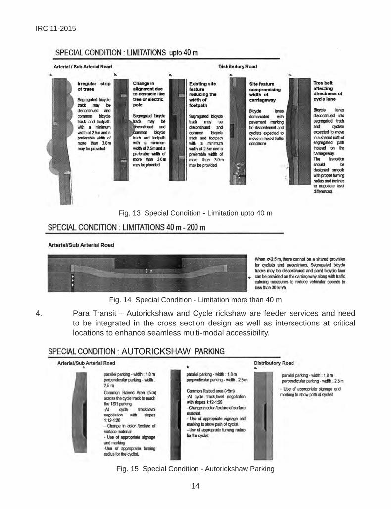
3. obstacles – Trees, encroachments etc. might create hindrance in the natural path of the cyclist. It is important to eliminate such obstacles such as light poles, encroachments, etc. At places, where trees also lie in the path of the cyclist, for a short stretch, it is important to change the course of the cyclist with the proper turning radius and bring him back to the natural path. Similarly, condition of bicycle infrastructure changes depending upon the length of such limitations. In certain conditions, the cyclists share with pedestrians a common path. This ranges between 3 m to 4 m and should not be more than a length of 40 m.
Fig. 12 Area Requirement for a Comman Cycle Track and Footpath
IRC:11-2015
14
Fig. 13 Special Condition - Limitation upto 40 m
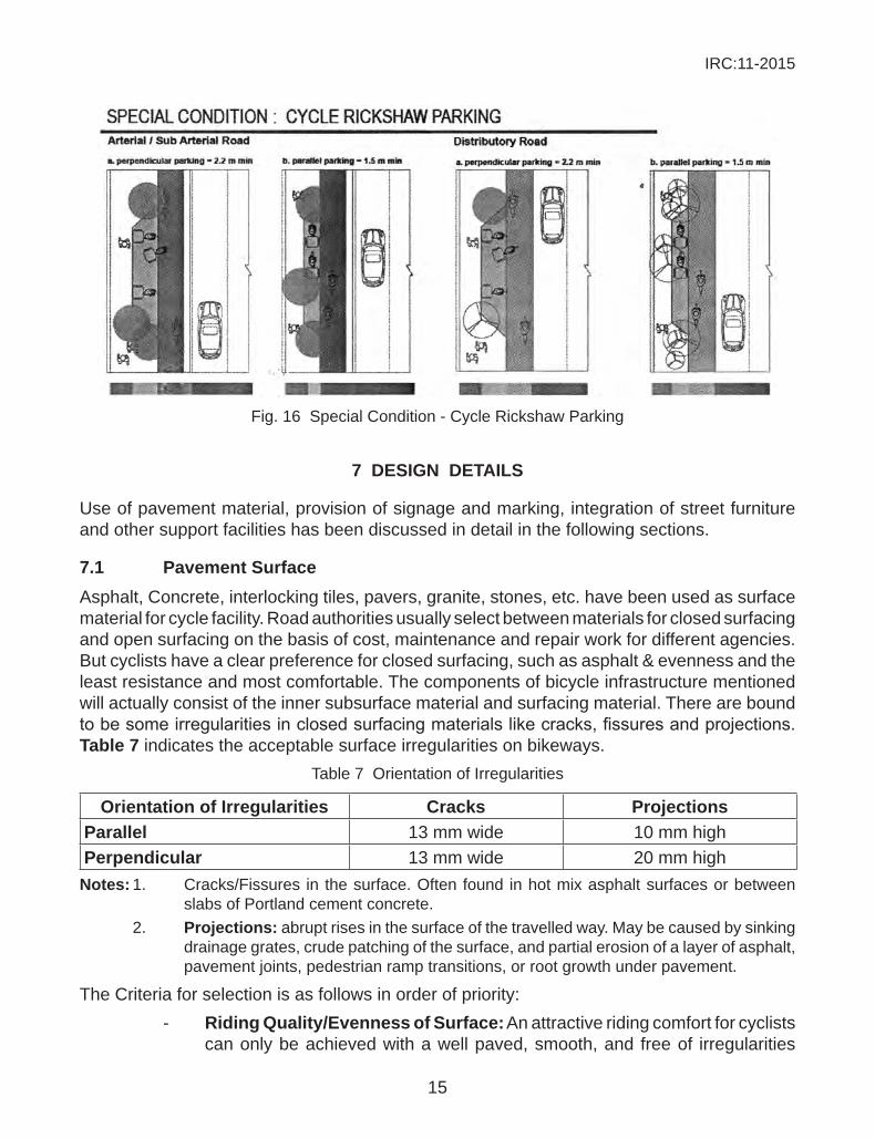
Fig. 14 Special Condition - Limitation more than 40 m
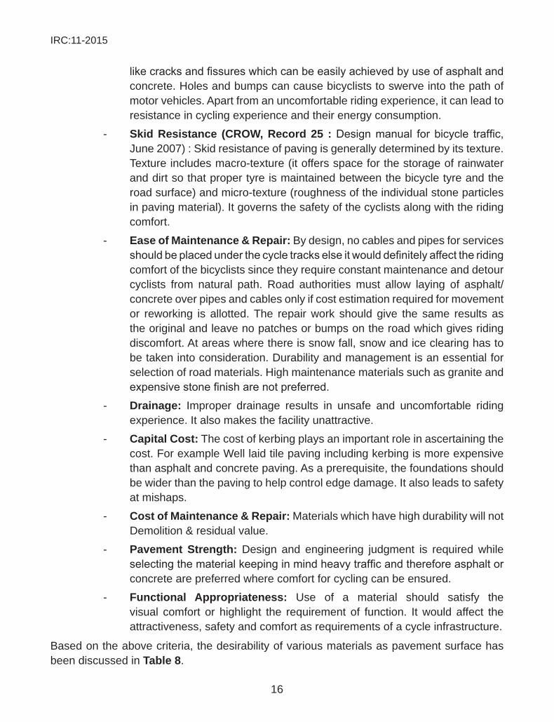
4. Para Transit – Autorickshaw and Cycle rickshaw are feeder services and need to be integrated in the cross section design as well as intersections at critical locations to enhance seamless multi-modal accessibility.
Fig. 15 Special Condition - Autorickshaw Parking
IRC:11-2015
15
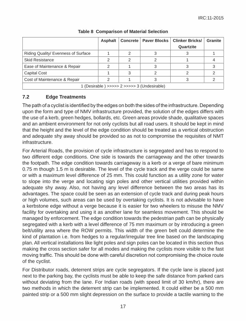
Fig. 16 Special Condition - Cycle Rickshaw Parking
7 design details
Use of pavement material, provision of signage and marking, integration of street furniture and other support facilities has been discussed in detail in the following sections.
7.1 pavement surfaceAsphalt, Concrete, interlocking tiles, pavers, granite, stones, etc. have been used as surface material for cycle facility. Road authorities usually select between materials for closed surfacing and open surfacing on the basis of cost, maintenance and repair work for different agencies. But cyclists have a clear preference for closed surfacing, such as asphalt & evenness and the least resistance and most comfortable. The components of bicycle infrastructure mentioned will actually consist of the inner subsurface material and surfacing material. There are bound tobesomeirregularitiesinclosedsurfacingmaterialslikecracks,fissuresandprojections.table 7 indicates the acceptable surface irregularities on bikeways.
Table 7 Orientation of Irregularities
orientation of irregularities cracks projectionsparallel 13 mm wide 10 mm highperpendicular 13 mm wide 20 mm high
notes: 1. Cracks/Fissures in the surface. Often found in hot mix asphalt surfaces or between slabs of Portland cement concrete.
2. projections: abrupt rises in the surface of the travelled way. May be caused by sinking drainage grates, crude patching of the surface, and partial erosion of a layer of asphalt, pavement joints, pedestrian ramp transitions, or root growth under pavement.
The Criteria for selection is as follows in order of priority: - Riding Quality/evenness of surface: An attractive riding comfort for cyclists
can only be achieved with a well paved, smooth, and free of irregularities
IRC:11-2015
16
likecracksandfissureswhichcanbeeasilyachievedbyuseofasphaltandconcrete. Holes and bumps can cause bicyclists to swerve into the path of motor vehicles. Apart from an uncomfortable riding experience, it can lead to resistance in cycling experience and their energy consumption.
- skid Resistance (cRow, Record 25 :Designmanual forbicycle traffic,June 2007) : Skid resistance of paving is generally determined by its texture. Texture includes macro-texture (it offers space for the storage of rainwater and dirt so that proper tyre is maintained between the bicycle tyre and the road surface) and micro-texture (roughness of the individual stone particles in paving material). It governs the safety of the cyclists along with the riding comfort.
- ease of maintenance & Repair: By design, no cables and pipes for services shouldbeplacedunderthecycletrackselseitwoulddefinitelyaffecttheridingcomfort of the bicyclists since they require constant maintenance and detour cyclists from natural path. Road authorities must allow laying of asphalt/concrete over pipes and cables only if cost estimation required for movement or reworking is allotted. The repair work should give the same results as the original and leave no patches or bumps on the road which gives riding discomfort. At areas where there is snow fall, snow and ice clearing has to be taken into consideration. Durability and management is an essential for selection of road materials. High maintenance materials such as granite and expensivestonefinisharenotpreferred.
- drainage: Improper drainage results in unsafe and uncomfortable riding experience. It also makes the facility unattractive.
- capital cost: The cost of kerbing plays an important role in ascertaining the cost. For example Well laid tile paving including kerbing is more expensive than asphalt and concrete paving. As a prerequisite, the foundations should be wider than the paving to help control edge damage. It also leads to safety at mishaps.
- cost of maintenance & Repair: Materials which have high durability will not Demolition & residual value.
- pavement strength: Design and engineering judgment is required while selectingthematerialkeepinginmindheavytrafficandthereforeasphaltorconcrete are preferred where comfort for cycling can be ensured.
- functional appropriateness: Use of a material should satisfy the visual comfort or highlight the requirement of function. It would affect the attractiveness, safety and comfort as requirements of a cycle infrastructure.
Based on the above criteria, the desirability of various materials as pavement surface has been discussed in table 8.
IRC:11-2015
17
table 8 comparison of material selection
asphalt concrete paver Blocks clinker Bricks/Quartzite
granite
Riding Quality/ Evenness of Surface 1 2 3 3 1Skid Resistance 2 2 2 1 4Ease of Maintenance & Repair 2 1 3 3 3Capital Cost 1 3 2 2 2Cost of Maintenance & Repair 2 1 3 3 2
1 (Desirable ) >>>>> 2 >>>>> 3 (Undesirable)
7.2 edge treatmentsThepathofacyclistisidentifiedbytheedgesonboththesidesoftheinfrastructure.Dependingupon the form and type of NMV infrastructure provided, the solution of the edges differs with the use of a kerb, green hedges, bollards, etc. Green areas provide shade, qualitative spaces and an ambient environment for not only cyclists but all road users. It should be kept in mind that the height and the level of the edge condition should be treated as a vertical obstruction and adequate shy away should be provided so as not to compromise the requisites of NMT infrastructure.
For Arterial Roads, the provision of cycle infrastructure is segregated and has to respond to two different edge conditions. One side is towards the carriageway and the other towards the footpath. The edge condition towards carriageway is a kerb or a verge of bare minimum 0.75 m though 1.5 m is desirable. The level of the cycle track and the verge could be same or with a maximum level difference of 25 mm. This could function as a utility zone for water to slope into the verge and locating sign poles and other vertical utilities provided within adequate shy away. Also, not having any level difference between the two areas has its advantages. The space could be seen as an extension of cycle track and during peak hours or high volumes, such areas can be used by overtaking cyclists. It is not advisable to have a kerbstone edge without a verge because it is easier for two wheelers to misuse the NMV facility for overtaking and using it as another lane for seamless movement. This should be managed by enforcement. The edge condition towards the pedestrian path can be physically segregated with a kerb with a level difference of 75 mm maximum or by introducing a green belt/utility area where the ROW permits. This width of the green belt could determine the kind of plantation i.e. from hedges to a regular/irregular tree line based on the landscaping plan. All vertical installations like light poles and sign poles can be located in this section thus making the cross section safer for all modes and making the cyclists more visible to the fast movingtraffic.Thisshouldbedonewithcarefuldiscretionnotcompromisingthechoicerouteof the cyclist.
For Distributor roads, deterrent strips are cycle segregators. If the cycle lane is placed just next to the parking bay, the cyclists must be able to keep the safe distance from parked cars without deviating from the lane. For Indian roads (with speed limit of 30 km/hr), there are two methods in which the deterrent strip can be implemented. It could either be a 500 mm painted strip or a 500 mm slight depression on the surface to provide a tactile warning to the
IRC:11-2015
18
parked vehicle. In case of distributor roads, since the cycle lane is painted, if there could be a segregator between the footpath and the painted lane, the collection chamber could be put there which would prevent installation of grating in the lane and would prevent injuries/ accidents of cyclists.
7.3 Road furniture & support facilitiesStreet furniture and support facilities are important elements that enhance the comfort, visual quality, convenience and security for cyclists and pedestrians. Street furniture includes benches, bollards, etc. They provide comfort for pedestrians and a rest area for cyclists. They can help in identifying an area of different function. Few points should be kept while this is used: - Vandalism Proof. The most important feature of any street furniture is that it
shouldbevandalismproof.Thefactthatsucharefixedinthepublicrealmanditisverydifficultforroadauthoritiestokeeparoundtheclockmaintenancemakes this quality of utmost importance.
- Easy to install. Otherwise road managers would require special equipment to install them making it less favourable to use.
- Requires less or no maintenance. - Attractive design. - Economical design. - Ease in production.Supportfacilitiessuchashawkersandstreetvendorsareasmallyetsignificantcomponentof road users. Their presence on the street not only helps increase safety, but their services provide convenience to cyclists. Their presence is already admissive on the street roads; however they are not integrated in the road design. Their integration affects the comfort and the safety of cyclists. Incase no provision is facilitated and no integration by design is undertaken, there is bound to be an encroachment on to the infrastructure provided for other users especially cyclists, which would push the users into unsafe conditions.
A detailed discussion for the determinant factors of the above has been discussed in IRC:103-1988: Guidelines for pedestrian facilities (1988).
7.4 illuminationStreet lighting is an important component that makes the available space legible for each road user. The illumination of a street is governed by the design speed. For cyclists, lighting also adds to the comfort while riding. In fact, lighting is the basic street furniture requirement thatwillhelpinfunctioningoftheentirebicycleinfrastructurenetwork.Lightingspecifications(based on design for Delhi BRT Corridor) for a cycle facility are as follows: ● Atnopointalongthe lanesaveragehorizontal illuminanceshouldbe less
than minimum 40 lux. ● AtnopointalongthelanesVerticalilluminanceshouldbelessthanMinimum:
20.0 lux (Measured at 1.5 m above roadway in both directions parallel to the roadway).
IRC:11-2015
19
● Uniformity Ratio: (E Min / E Avg): 40% ● Mounting height: 6 m (luminaires should be located to avoid formation of
shadows from tree foliage). ● Bracket length: 0.5 m ● Luminaire to luminaire Spacing: 20 m (Lesser spacing than this will be
helpful) ● Type of Lamp: Metal Halidelocation of poles is also decided based upon the category of the road. It could be the central verge or at sides where a segregated cycle facility is available. Two luminaries can be mounted on a pole located between the carriageway and the cycle track at different height to light the required area with the required lux levels. This would also reduce the number of poles required and the vertical clutter on any given road.
color of light: Street lighting should produce enough intensity required for face recognition and objects from a particular sight distance. Especially for the purpose of social safety, women and children are a special group for whom the color of light is of added importance. White light is a preferred choice.
7.5 Traffic CalmingThe variation in speeds between vehicles is the major cause of accidents. Establishing a speed zone is a design-enforced methodology where the three basic elements, infrastructure, roadsusersand thevehicle,of the trafficsystemshouldbeadapted toeachother.Hereinfrastructure design can be instrumental in ensuring safety by affecting the user and vehicle behaviour. Influencing theuserbehaviourbyusingvisualwarnings/pre-warningssuchassignage and markings or physical and psychological warnings like humps, speed tables and table tops help inform the user in a visual or palpable way about a change in the situation. Similarly, influencing the vehicle behaviour by a specific change in geometric alignmentreduces speed. They need to be logistically positioned and be visible from a distance for the user to react. Signs and marking should be effectively placed and are used as advance warning/pre-warning to road users.
Trafficcalmingincludesnarrowing,chicanes,speedhumps,rumblestripsandtabletops.Itisimportanttounderstandthattrafficcalmingistakenuptobringdownthevehicularspeedsimilar to that of NMT. In an Indian scenario, chicanes and narrowing have not been as successful as in the west due to high number of two wheelers. Also, to curb speeds of two wheelers the speed humps should be created on the entire length of the carriageway, else two wheelers detour path and pass at grade creating hazard for cyclists. Speed Humps are oneofthemosteffectivetrafficcalmingdevicesandcanbeusedonvirtuallyanykindofroad,with posted speed limits of up to 50 km/hr. Speed Humps most successful for Indian streets are trapezoidal and table tops.
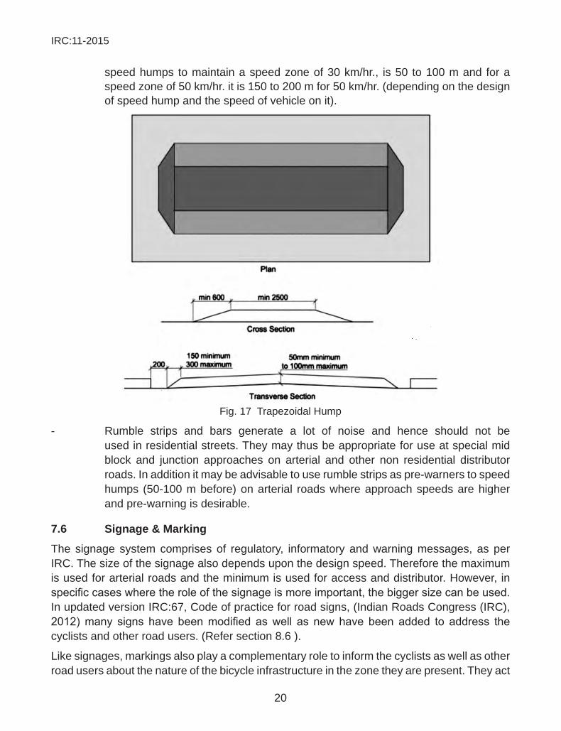
- trapezoidal humpshaveaflattop,whichisgenerally2.5mwide.Iftheflattopis8 m or more in width, it is known as the platform or table top (MOSTH, 2000) (also used as a barrier friendly infrastructure). The maximum gap required between
IRC:11-2015
20
speed humps to maintain a speed zone of 30 km/hr., is 50 to 100 m and for a speed zone of 50 km/hr. it is 150 to 200 m for 50 km/hr. (depending on the design of speed hump and the speed of vehicle on it).
Fig. 17 Trapezoidal Hump
- Rumble strips and bars generate a lot of noise and hence should not be used in residential streets. They may thus be appropriate for use at special mid block and junction approaches on arterial and other non residential distributor roads. In addition it may be advisable to use rumble strips as pre-warners to speed humps (50-100 m before) on arterial roads where approach speeds are higher and pre-warning is desirable.
7.6 signage & marking
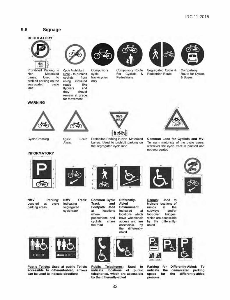
The signage system comprises of regulatory, informatory and warning messages, as per IRC. The size of the signage also depends upon the design speed. Therefore the maximum is used for arterial roads and the minimum is used for access and distributor. However, in specificcaseswheretheroleofthesignageismoreimportant,thebiggersizecanbeused.In updated version IRC:67, Code of practice for road signs, (Indian Roads Congress (IRC), 2012)many signs have beenmodified aswell as newhave been added to address thecyclists and other road users. (Refer section 8.6 ).
Like signages, markings also play a complementary role to inform the cyclists as well as other road users about the nature of the bicycle infrastructure in the zone they are present. They act
IRC:11-2015
21
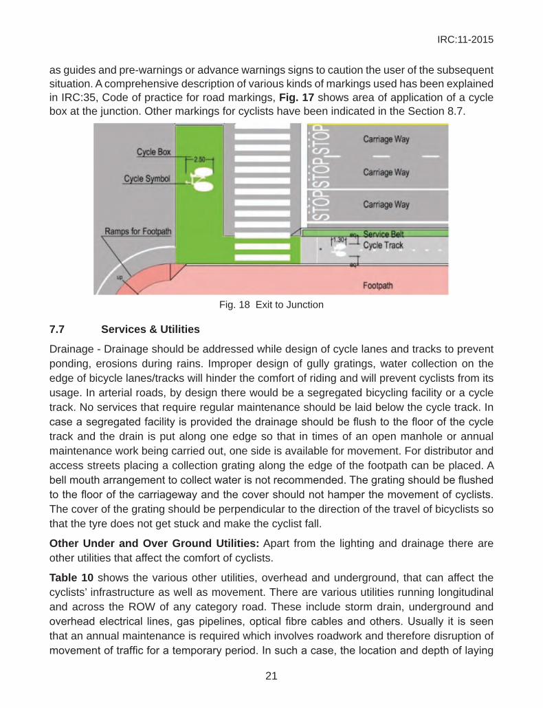
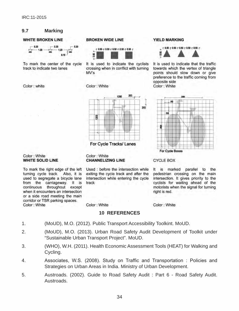
as guides and pre-warnings or advance warnings signs to caution the user of the subsequent situation. A comprehensive description of various kinds of markings used has been explained in IRC:35, Code of practice for road markings, fig. 17 shows area of application of a cycle box at the junction. Other markings for cyclists have been indicated in the Section 8.7.
Fig. 18 Exit to Junction
7.7 services & utilities
Drainage - Drainage should be addressed while design of cycle lanes and tracks to prevent ponding, erosions during rains. Improper design of gully gratings, water collection on the edge of bicycle lanes/tracks will hinder the comfort of riding and will prevent cyclists from its usage. In arterial roads, by design there would be a segregated bicycling facility or a cycle track. No services that require regular maintenance should be laid below the cycle track. In caseasegregatedfacilityisprovidedthedrainageshouldbeflushtothefloorofthecycletrack and the drain is put along one edge so that in times of an open manhole or annual maintenance work being carried out, one side is available for movement. For distributor and access streets placing a collection grating along the edge of the footpath can be placed. A bellmoutharrangementtocollectwaterisnotrecommended.Thegratingshouldbeflushedtothefloorofthecarriagewayandthecovershouldnothamperthemovementofcyclists.The cover of the grating should be perpendicular to the direction of the travel of bicyclists so that the tyre does not get stuck and make the cyclist fall.
other under and over ground utilities: Apart from the lighting and drainage there are other utilities that affect the comfort of cyclists.
table 10 shows the various other utilities, overhead and underground, that can affect the cyclists’ infrastructure as well as movement. There are various utilities running longitudinal and across the ROW of any category road. These include storm drain, underground and overheadelectrical lines,gaspipelines,opticalfibrecablesandothers.Usually it isseenthat an annual maintenance is required which involves roadwork and therefore disruption of movementoftrafficforatemporaryperiod.Insuchacase,thelocationanddepthoflaying
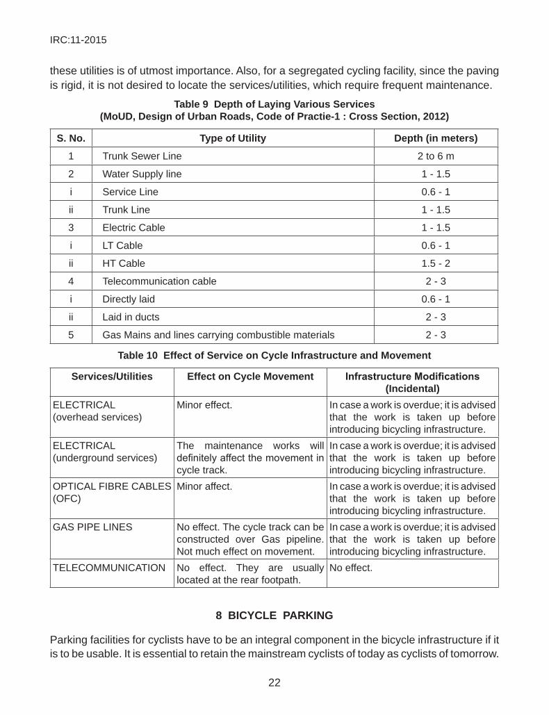
IRC:11-2015
22
these utilities is of utmost importance. Also, for a segregated cycling facility, since the paving is rigid, it is not desired to locate the services/utilities, which require frequent maintenance.
table 9 depth of laying Various services (moud, design of urban Roads, code of practie-1 : cross section, 2012)
s. no. type of utility depth (in meters)
1 Trunk Sewer Line 2 to 6 m
2 Water Supply line 1 - 1.5
i Service Line 0.6 - 1
ii Trunk Line 1 - 1.5
3 Electric Cable 1 - 1.5
i LT Cable 0.6 - 1
ii HT Cable 1.5 - 2
4 Telecommunication cable 2 - 3
i Directly laid 0.6 - 1
ii Laid in ducts 2 - 3
5 Gas Mains and lines carrying combustible materials 2 - 3
table 10 effect of service on cycle infrastructure and movement
services/utilities effect on cycle movement Infrastructure Modifications (incidental)
ELECTRICAL (overhead services)
Minor effect. In case a work is overdue; it is advised that the work is taken up before introducing bicycling infrastructure.
ELECTRICAL (underground services)
The maintenance works will definitelyaffectthemovementincycle track.
In case a work is overdue; it is advised that the work is taken up before introducing bicycling infrastructure.
OPTICAL FIBRE CABLES (OFC)
Minor affect. In case a work is overdue; it is advised that the work is taken up before introducing bicycling infrastructure.
GAS PIPE LINES No effect. The cycle track can be constructed over Gas pipeline. Not much effect on movement.
In case a work is overdue; it is advised that the work is taken up before introducing bicycling infrastructure.
TELECOMMUNICATION No effect. They are usually located at the rear footpath.
No effect.
8 Bicycle paRKing
Parking facilities for cyclists have to be an integral component in the bicycle infrastructure if it is to be usable. It is essential to retain the mainstream cyclists of today as cyclists of tomorrow.
IRC:11-2015
23
These commuters should be provided similar facilities/provisions as car users enjoy. Good parking facilities also help attract new users and thereby promote cycling. There is always a confusion to understand the terms parking and storage of bicycles. Internationally, parking is leaving a vehicle stationary other than during immediate boarding or alighting or during loading and unloading. Storing is placing a bicycle in a bicycle storage facility. A bicycle parking facility means a bicycle parking system (a structure intended to have one or more bicycles placed in or against it), a bicycle storage facility (a delineated and supervised space that is intended for placing bicycles) or a combination of them. (CROW, Record 25 : Design manualforbicycletraffic,June2007).
Provision of parking is not a new concept to the Indian sub-continent. Railways stations in most of the cities have a bicycle storage facility for commuters who travel to place of work using train. In residential areas, to ensure use of bicycles and even attract new bicyclists, places of gathering and market areas can have parking facilities. The class of economics is really varied for example there are already roads equal to the width of access streets within the residential area.
Also rickshaw-parking stands will help others who want to use a rickshaw to travel short distances and encourage using non-motorized modes. The advantage of cycle rickshaw parking over bicycle parking is that it would not require manning; theft is a very rare case and covers a very low share of investment in terms of infrastructure. Since it acts as feeder mode, it would cater to short trip lengths of 1.5-2 km, the introduction of frequency of cycle rickshaw parking would fairly increase in densely populated residential (passenger rickshaws) and commercial areas (passenger and goods rickshaws). The percentage of the space allocated for goods rickshaw parking would be higher rather than that of commercial areas. The elements of bicycle parking are as follows: 1. location: These locations could be at or in proximity of: Transit Stations,
Places of importance, Junctions/Interchange, Nodes. Measures by the government to provide public parking near informal households or slums, whichalsoareoriginpoints,woulddefinitelybefruitfultoacyclingrouteandthe network across the city.
2. space/area: Space allocation is based on the activity survey and the existing capacity of the corridor. It is also dependent upon the discretion of the designer. Usually, the space allocation should be 20%-30% more for optimum use in the future. Capacity requirement needs to be assessed in detail.
3. theft control:Theftpreventionwilldefinitelypromoteandincreasecyclingsince the users would see it as a safe mode. It should be kept in mind that investments to prevent thefts would only lead to increase in number of bicyclists and make it an attractive mode to choose.
4. manned or provided: Parking facilities can be manned or provided. While the manned provision needs an extra investment to make it theft free (hire security personnel), the latter is providing good fastening locking facilities where a place has already been designated.
IRC:11-2015
24
5. shade: Much needed for the Indian condition, shade is required for parking as required by the car users for the same. This could be done by the existing natural foliage or by use of temporary structures or other built provisions taken into consideration.
forms of Bicycle parking: The most popular form currently used in a number of cities is the wheelclampsortheinclinedwheelbraces,usedinofficeproperties,schools,metrostations/railway stations where the risk of theft is quite low. The other types of form of bicycle parking facilities used are: 1. Hanging system bars 2. Hanging system on walls 3. Tiered racks – such is used at railway stations where the cyclists travel to
suburbs for work. 4. Binder racks 5. Bolt locking system – frame type/wheel lock 6. Fastening poles 7. Support rack 8. Brace rackOthers, where the volume of bicycle parking is larger are: Canopies and designated parking lots
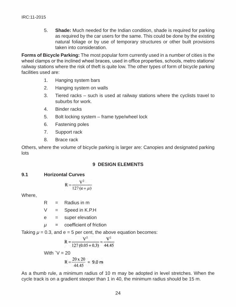
9 design elements
9.1 horizontal curves
Where, R = Radius in m V = Speed in K.P.H e = super elevation μ = coefficientoffrictionTaking μ = 0.3, and e = 5 per cent, the above equation becomes:
With `V = 20
As a thumb rule, a minimum radius of 10 m may be adopted in level stretches. When the cycle track is on a gradient steeper than 1 in 40, the minimum radius should be 15 m.

IRC:11-2015
25
9.2 stopping sight distanceThe stopping sight distance is given by the sum of the distance travelled during perception and brake reaction time (d1 metres) and the distance travelled under the application of brakes (d2 metres).
Taking 2.5 secs as the perception and brake reaction time, d1 = ν t
=
= 0.695 VIn the above equation, ν = speed in m/sec and v = speed in K.P.HThe braking distance d2 is given by v2 = 2.a.d2
Where, ν = speedinm/sec a = deceleration caused f = coefficientoffriction and g = acceleration due to gravity = 9.81 m/sec2
Taking f = 0.3
d2 =
To account for the upward or downward gradient,
d2 =
Where, G = gradient in percent(+ is to be used for upward travel
and - is to be used for downward travel)
For a speed of 20 KPH, the stopping sight distance becomes:
d1 + d2 = 0.695 × 20 +
= 13.9 + 5.25
= 19.14, say 20 m on level stretches
IRC:11-2015
26
9.3 Vertical curvesVertical curves at changes of grade shall have a minimum radius of 200 metres for summit curves and 100 metres for valley curves. This is applicable for the entire road width and not cyclefacilityspecific.
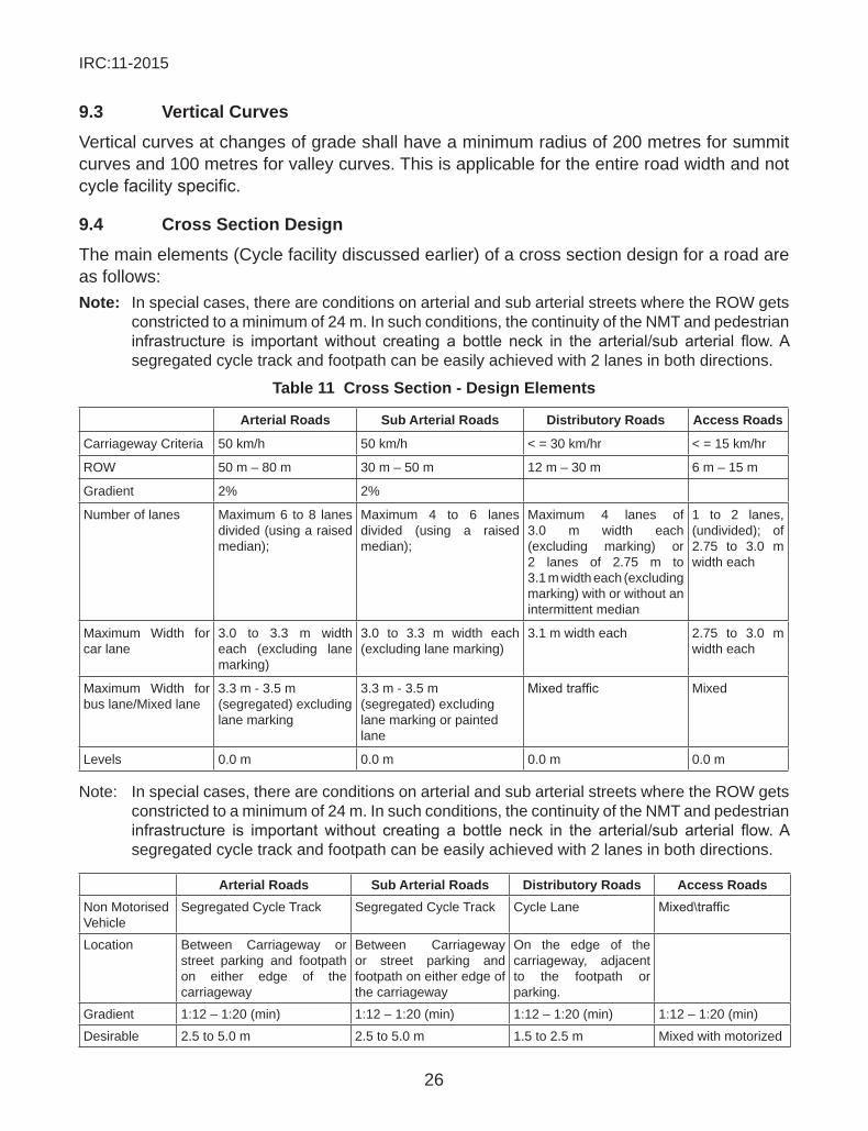
9.4 cross section designThe main elements (Cycle facility discussed earlier) of a cross section design for a road are as follows:note: In special cases, there are conditions on arterial and sub arterial streets where the ROW gets
constricted to a minimum of 24 m. In such conditions, the continuity of the NMT and pedestrian infrastructure is importantwithout creating a bottle neck in the arterial/sub arterial flow.Asegregated cycle track and footpath can be easily achieved with 2 lanes in both directions.
table 11 cross section - design elements
arterial Roads sub arterial Roads distributory Roads access Roads
Carriageway Criteria 50 km/h 50 km/h < = 30 km/hr < = 15 km/hr
ROW 50 m – 80 m 30 m – 50 m 12 m – 30 m 6 m – 15 m
Gradient 2% 2%
Number of lanes Maximum 6 to 8 lanes divided (using a raised median);
Maximum 4 to 6 lanes divided (using a raised median);
Maximum 4 lanes of 3.0 m width each (excluding marking) or 2 lanes of 2.75 m to 3.1 m width each (excluding marking) with or without an intermittent median
1 to 2 lanes, (undivided); of 2.75 to 3.0 m width each
Maximum Width for car lane
3.0 to 3.3 m width each (excluding lane marking)
3.0 to 3.3 m width each (excluding lane marking)
3.1 m width each 2.75 to 3.0 m width each
Maximum Width for bus lane/Mixed lane
3.3 m - 3.5 m (segregated) excluding lane marking
3.3 m - 3.5 m (segregated) excluding lane marking or painted lane
Mixedtraffic Mixed
Levels 0.0 m 0.0 m 0.0 m 0.0 m
Note: In special cases, there are conditions on arterial and sub arterial streets where the ROW gets constricted to a minimum of 24 m. In such conditions, the continuity of the NMT and pedestrian infrastructure is importantwithout creating a bottle neck in the arterial/sub arterial flow.Asegregated cycle track and footpath can be easily achieved with 2 lanes in both directions.
arterial Roads sub arterial Roads distributory Roads access RoadsNon Motorised Vehicle
Segregated Cycle Track Segregated Cycle Track Cycle Lane Mixed\traffic
Location Between Carriageway or street parking and footpath on either edge of the carriageway
Between Carriageway or street parking and footpath on either edge of the carriageway
On the edge of the carriageway, adjacent to the footpath or parking.
Gradient 1:12 – 1:20 (min) 1:12 – 1:20 (min) 1:12 – 1:20 (min) 1:12 – 1:20 (min)
Desirable 2.5 to 5.0 m 2.5 to 5.0 m 1.5 to 2.5 m Mixed with motorized
IRC:11-2015
27
Lane width vehiculartraffic
Level + 50 mm to +100 mm +50 mm to +100 mm 0.0 m 0.0 m
Minimum Width 2.2 for a two lane cycle track and 3 m to 4 m for a common cycle track and footpath (not more than a length of 40m.
2.2 for a two lane cycle track and 3 m to 4 m for a common cycle track and footpath (not more than a length of 40 m).
1.2 m painted cycle lane.
Mixed condition
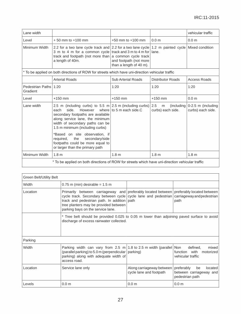
*TobeappliedonbothdirectionsofROWforstreetswhichhaveuni-directionvehiculartraffic
Arterial Roads Sub Arterial Roads Distributor Roads Access Roads
Pedestrian Paths Gradient
1:20 1:20 1:20 1:20
Level +150 mm +150 mm +150 mm 0.0 m
Lane width 2.5 m (including curbs) to 5.5 m each side. However where secondary footpaths are available along service lane, the minimum width of secondary paths can be 1.5 m minimum (including curbs)
*Based on site observation, if required, the secondary/side footpaths could be more equal to or larger than the primary path
2.5 m (including curbs) to 5 m each side.C
2.5 m (including curbs) each side.
0-2.5 m (including curbs) each side.
Minimum Width 1.8 m 1.8 m 1.8 m 1.8 m
*TobeappliedonbothdirectionsofROWforstreetswhichhaveuni-directionvehiculartraffic
Green Belt/Utility Belt
Width 0.75 m (min) desirable = 1.5 m
Location Primarily between carriageway and cycle track. Secondary between cycle track and pedestrian path. In addition tree planters may be provided between parking bays on the service lane.
preferably located between cycle lane and pedestrian path
preferably located between carriageway and pedestrian path
* Tree belt should be provided 0.025 to 0.05 m lower than adjoining paved surface to avoid discharge of excess rainwater collected.
Parking
Width Parking width can vary from 2.5 m (parallel parking) to 5.0 m (perpendicular parking) along with adequate width of access road.
1.8 to 2.5 m width (parallel parking)
Non defined, mixedfunction with motorized vehiculartraffic
Location Service lane only Along carriageway between cycle lane and footpath
preferably be located between carriageway and pedestrian path
Levels 0.0 m 0.0 m 0.0 m
IRC:11-2015
28
Fig. 19 Cross Section Elements
IRC:11-2015
29
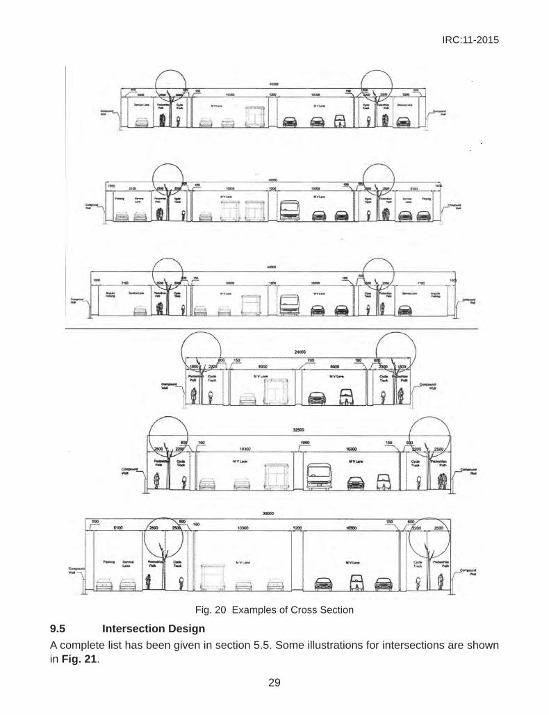
Fig. 20 Examples of Cross Section
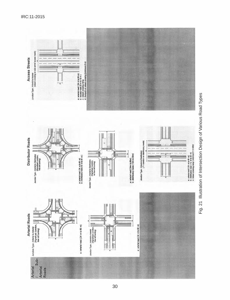
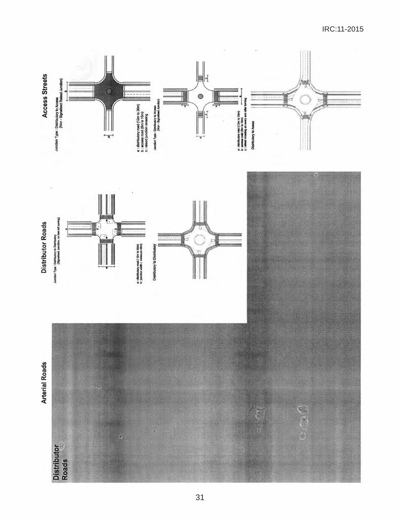
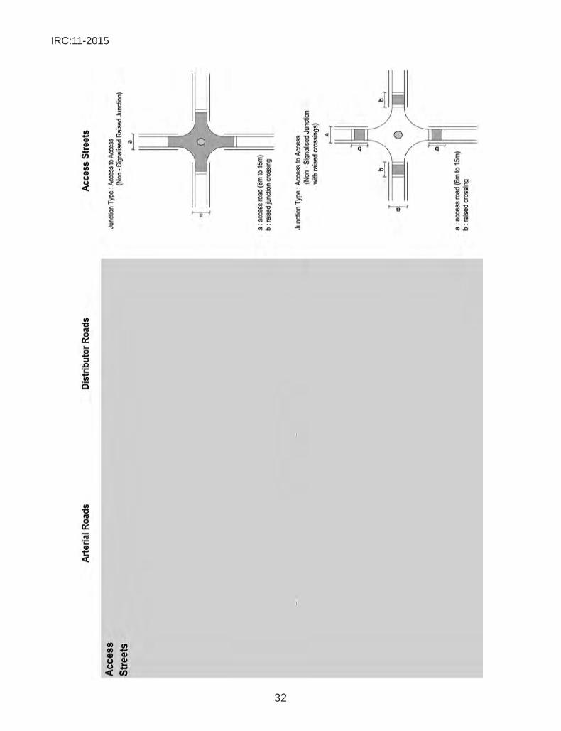
9.5 intersection designA complete list has been given in section 5.5. Some illustrations for intersections are shown in fig. 21.
IRC:11-2015
30
Fig.
21
Illu
stra
tion
of In
ters
ectio
n D
esig
n of
Var
ious
Roa
d Ty
pes
IRC:11-2015
31
IRC:11-2015
32
IRC:11-2015
33
9.6 signage
IRC:11-2015
34
9.7 marking
10 RefeRences
1. (MoUD), M.O. (2012). Public Transport Accessibility Toolkint. MoUD.
2. (MoUD), M.O. (2013). Urban Road Safety Audit Development of Toolkit under “Sustainable Urban Transport Project”. MoUD.
3. (WHO), W.H. (2011). Health Economic Assessment Tools (HEAT) for Walking and Cycling.
4. Associates, W.S. (2008). Study on Traffic and Transportation : Policies andStrategies on Urban Areas in India. Ministry of Urban Development.
5. Austroads. (2002). Guide to Road Safety Audit : Part 6 - Road Safety Audit. Austroads.
IRC:11-2015
35
6. BIS, B.O. (1981). BIS 1944-7:1981, Code of Practice for Lightning of Public Thoroughfare. New Delhi.
7. County, C.C. (2005). Pedestrian Access and Mobility - a Code of Practice (2nd ed.). Council Cheshire County.
8. CROW.(June2007).Record25:DesignManualforBicycleTraffic.CROW.
9. CROW. (1996). Sign up for the Bike : Design Manual for a Cycle Friendly Infrastructure - Record 10. CROW.
10. Fagard, R. (1995). Prescription and Results of Physical Activity. J Cardiovasc Pharmacol , 25, S20-S27.
11. G. Tiwari, D. (2012). NMT Infrastructure in India, Investment Policy and Design - Draft Report. UNEP RISO Center.
12. Ghate, A.T., & Sundar, S. (2010). Infrastructure Development in a Low Carbon Economy. New Delhi: Oxford University Press.
13. Government of India. (2005). NUTP, National Urban Transport Policy. Ministry of Urban Development.
14. Hillsdon M, T.M. (1995). RCTs of Physical Activity Promotion in Free Living Populations: a Review. J Epidemiol Community Health , 49, 448-453.
15. Indian Roads Congress (IRC), M.O. (2012). IRC:67, Code of Practice for Road Signs (3rd ed.). IRC.
16. IRAP, I.R. (2009). Star Rating Roads for Safety - IRAP Methodology. IRAP.
17. IRC:1988. IRC:103: Guidelines for Pedestrian Facilities. IRC.
18. IRC:106-1990. IRC:106, Guidelines for Capacity of Urban Roads in Plain Areas. New Delhi: IRC.
19. IRC:11-1962. IRC:11, Recommended Practice for the Design and Layout of Cycle Tracks. New Delhi: IRC.
20. IRC:35-1997. IRC:35 Code of Practice for Road Markings. New Delhi: IRC.
21. IRC:35-1970. IRC:35, Guidelines for Cyclists Crossings. New Delhi: IRC.
22. IRC:67-2001. IRC: 67, Code of Practice for Road Signs. New Delhi: IRC.
23. IRC69-1977. IRC: 69, Space Standards for Roads in Urban Areas, i, India,. New Delhi: IRC.
24. IRC:70-1977. IRC:70,GuidelinesonRegulationandControlofMixedTraffic inUrban Areas. New Delhi: IRC.
25. IRC:86-1983. IRC:86, Geometric Design Standards for Roads Inurban Areas. New Delhi: IRC.
26. IRC:92-1985. IRC:92, Guidelines for the Design of Interchanges in Urban Areas. New Delhi: IRC.
IRC:11-2015
36
27. IRC:98-1997. IRC:98, Guidelines on Accommodation of Utility Services on Roads in Urban Areas. New Delhi: IRC.
28. IUT. (2012). Code of Practice - 2. MoUD.
29. Jain, H. (2013). Development of a Vicycle Demand Estimation Model Incorporating Land Use Sensitive Parameters: Case of Pune city, India. PHD Dissertation, IIT Delhi.
30. JnNURM, G. (2005-12). JnNURM.
31. Mohan, D. (2008). Health Issues in Bicyling. In Bicycling in Asia (pp. 117-120). Interface for Cycling Expertise.
32. Mohan, D., Tiwari, G., & Mukherjee, S. (2012-13). A Study on Community Design forTrafficSafety.TRIPP.
33. MOSTH,I.-D.D.(2000).TrafficCalmingReport(MOSTResearchSchemeT-3),State-of-the-Art-Report. Ministry of Surface Transport and Highway.
34. MoUD. (2012). Design of Urban Roads, Code of Practice (Part-4). Ministry of Urban Development.
35. MoUD. (2012). Design of Urban Roads, Code of Practice-1 : Cross section. MoUD.
36. MoUD. Service Level Benchmarks for Urban Transport. MoUD.
37. NHAI, T. (2010). Work Zone Safety Manual. National Highways Authority of India, NHAI.
38. NMSH, N.M. (2011). Report of the Sub-Committee on Urban Transport.
39. Singh, G. (2011). Comprehensive Assessment of Cycle Tracks in Pune. Parisar.
40. SP:55, I. (2013). SP 55, Indian Road Congress. IRC.
41. Stanadards, B.o. (1981). IS 1944-7 : Code of Practice for Lightning of Public Thoroughfare. New Delhi.
42. Thompson MJ, R.F. (2001). Bicycle-Related Injuries. American Family Physician, 2007 (14), 63(10).
43. Tiwari, G. (2002). Urban Transport Priorities: Meeting the Challenge of Socio-economic Diversity in Cities, a Case Study of Delhi, India. Cities, 19 (2).
44. Tiwari, G., & Jain, D. (n.d.). Impact of Transport Infrastructure Improvement Strategies on Co2 Emission and Fuel Consumption: Case of Indian Cities.
45. Tiwari, G., & Jain, H. (2008). Bicyling in Urban India. In Bicyling in Asia (pp. 9-26). Interface for Cycling Expertise,I-ce, Netherlands.
46. Tota, K. (April 1999). The Role of Non-Motorized Transport in Sustainable Urban TransportSystems:APreliminaryAnalysisofCostsandBenefitsofNon-Motorizedand Bus Priority Measures on Vikas Marg, Delhi, prepared for TERI.
IRC:11-2015
37
towards safer Roads.1. TRIPP. (2006). Survey Report, Bicycle Use and Barriers to Use, Transportation
Research and Injury Prevention Program (TRIPP) IIT Delhi, Institute of Democratic Studies (IDS) for LOCOMOTIVES (I-ce) project.
2. TRIPP. Work Zone Safety Manual. IIT - Delhi.
3. TRIPP, R. (2005). First Delhi BRT Corridor - A Design Summary- Ambedkar Nagar to Delhi Gate. New Delhi.
4. UNEP, I. D. (2012). Toolkit for Preparing Low Carbon Comprehensive Mobility Plan (LCMP). UNEP.
5. Woodcock,J.,Mohan,D.,&Tiwari,G.(2009).PublicHealthBenefitsofStrategiesto Reduce Greenhouse-Gas Emmisions : Urban Land Transport. Lancet (374), 1930-43.
____________