Embed Size (px)
Citation preview
Recom Engineering
Vacation Work Experience Report
Ahsanul Kabir
13549541
Department of Mechanical Engineering
Curtin University

Introduction to the Company
Recom Engineering is an Australian owned company, established in 1984 for the purpose of
remanufacturing used or faulty compressors and selling them directly to other businesses.
Remanufactured compressors often have a significant cost advantage without having any effect
on the reliability. The Company owns complete re manufacturing facilities in Melbourne,
Brisbane, Sydney and Perth. Customers of the company range from the Australian Navy, mining
and fishing industry, major hospitals to the compressor manufacturing companies themselves
such as Trane, Carrier, Bitzer and York (http://www.recom-eng.com.au/, accessed 16th June 2012).
Generalized Summary of work process
The compressors are dropped off to the warehouse workshop where first it is disassembled in
the following sequence. Initially an electrical test is performed on the rotor circuits to assess if
there were any electrical faults that may have caused the ultimate failure of the compressor.
Relief valves are checked to get rid of any compressed air inside the sump. The oil cap is then
opened to allow the oil to leak out of the sump. After all the oil is drained the heads of the
compressors are unscrewed. If it is a high priority job that needs quick assessment power tools
run on air pressure are used to dismantle it. After the heads are removed, the valve plates can
be taken off for an initial evaluation. If broken pieces of metal make its way into the cylinder
this scars the valve plate as well as the cylinder walls. Also the color of the oil can be used as an
early indicator for probable cause of failure.
The two ends are then unscrewed, one containing the rotor (not applicable to open drives) and
the other containing the oil pump. Following this the compressor is made to stand vertically on
the end containing the rotor and the sump plate is opened. The damage (if any) to the
crankshaft and con-rods is visible from here. Often shattered pieces of con-rods are found in
the sump. The caps of the connecting rods are first unscrewed and removed from the sump
side. The piston and the I beam section of the con rod usually comes out through the head side
(top of the compressor). After all the pistons and the con rods have been removed, the
crankshaft can then finally be taken out of the sump.
For compressors those are there just for routine maintenance, without any visible damage, the
crankshaft and the con rod bores are measured with micro meter screw gauge at all the
locations that held the con rods. The bores would definitely be larger, but if the difference in
readings between the bore diameter and the crankshaft diameter was found to be larger than
4/1000 of an inch, the crank was considered to be worn and needed replacement.
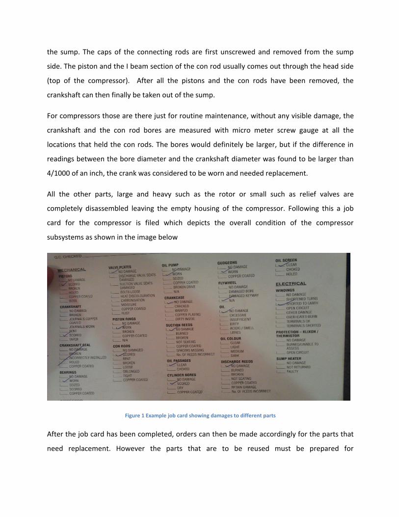
All the other parts, large and heavy such as the rotor or small such as relief valves are
completely disassembled leaving the empty housing of the compressor. Following this a job
card for the compressor is filed which depicts the overall condition of the compressor
subsystems as shown in the image below
Figure 1 Example job card showing damages to different parts
After the job card has been completed, orders can then be made accordingly for the parts that
need replacement. However the parts that are to be reused must be prepared for
remanufacturing. This is done by washing them and performing surface operations on them
when required.
First all the remains of the used gaskets must be removed manually. This can be a tedious
process as sometimes high working pressures and temperatures tend to stamp the gaskets into
the metal surface. In extreme cases special chemicals are used to soak the gaskets overnight so
that they can be removed the next day. After all the surfaces have been cleaned manually, with
gasket remover sand paper and or foam abrasive, they are sent off to washing. First they are
put in a synthetic kerosene wash. Inside this machine there is a circular tray made of thick steel
wires, which rotates at high speeds as a mixture of high pressure kerosene and water is sprayed
over it. This removes all the dirt and oil from the metal parts. Parts that are usually sent to the
kero wash include small nuts and bolts, pistons piston rings, connecting rods, crankshaft, valve
plates in fact everything that does not have rust on them. Rust prone parts are usually dealt
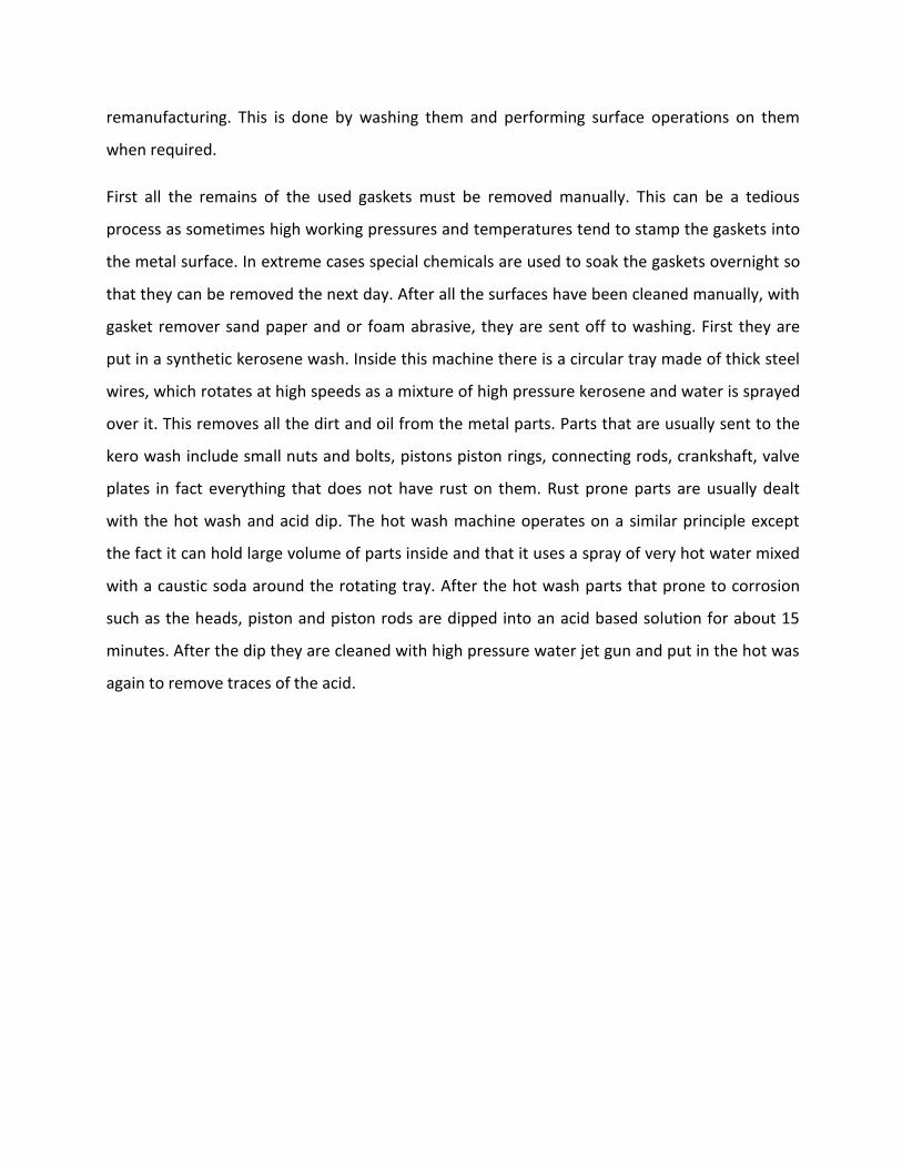
with the hot wash and acid dip. The hot wash machine operates on a similar principle except
the fact it can hold large volume of parts inside and that it uses a spray of very hot water mixed
with a caustic soda around the rotating tray. After the hot wash parts that prone to corrosion
such as the heads, piston and piston rods are dipped into an acid based solution for about 15
minutes. After the dip they are cleaned with high pressure water jet gun and put in the hot was
again to remove traces of the acid.
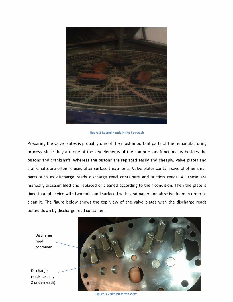
Figure 2 Rusted heads in the hot wash
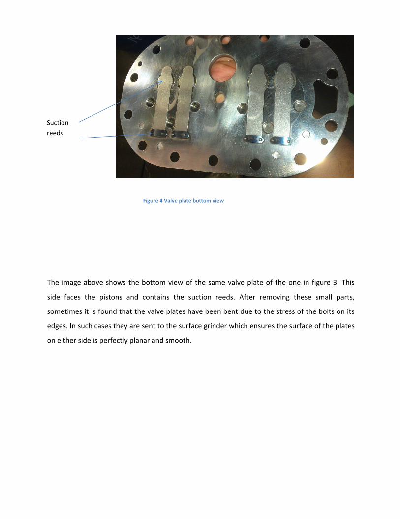
Preparing the valve plates is probably one of the most important parts of the remanufacturing
process, since they are one of the key elements of the compressors functionality besides the
pistons and crankshaft. Whereas the pistons are replaced easily and cheaply, valve plates and
crankshafts are often re used after surface treatments. Valve plates contain several other small
parts such as discharge reeds discharge reed containers and suction reeds. All these are
manually disassembled and replaced or cleaned according to their condition. Then the plate is
fixed to a table vice with two bolts and surfaced with sand paper and abrasive foam in order to
clean it. The figure below shows the top view of the valve plates with the discharge reads
bolted down by discharge read containers.
Dischargereeds (usually2 underneath)
Dischargereedcontainer
Figure 3 Valve plate top view
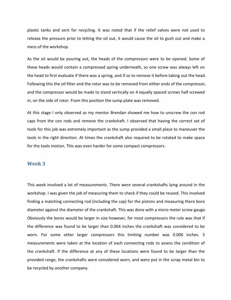
The image above shows the bottom view of the same valve plate of the one in figure 3. This
side faces the pistons and contains the suction reeds. After removing these small parts,
sometimes it is found that the valve plates have been bent due to the stress of the bolts on its
edges. In such cases they are sent to the surface grinder which ensures the surface of the plates
on either side is perfectly planar and smooth.
Figure 4 Valve plate bottom view
Suctionreeds

The crankshaft is mounted on the lathe and given some sand paper treatment to make its
surface clean and smooth unless it is severely damaged by broken connecting rods. Crankshafts
are expensive to replace therefore often it might not be economical to go through with
remanufacturing compressors with damaged crankshafts.
When all the parts are ready for remanufacturing, and the new ordered parts and gaskets have
arrived the assembling process can proceed. It is done by the reverse order as disassembling.
All the parts are initially given a spray and wipe with flushing agent to get rid of any remaining
residues from the washing processes. First the housing is made to stand vertically as mentioned
Figure 6 Surface grinder Figure 5 Valve plate after operation in the surface grinder

before and the crankshaft is inserted through it. The pistons are attached with con rods with
gudgeon pins. The con rod caps are manufactured specific to the con rod I beam sections.
Hence they must be marked to avoid mix up. The piston rings are then put on the pistons. Some
pistons have a specific sequence of rings; hence care should be taken to ensure that the rings
having a light indentation saying “TOP” are facing the top side (pointing outside from the sump).
Also the openings in the rings must be facing away from the gudgeon pins and each other. The
pistons are inserted into the cylinders from the outside and with the help of a piston ring
compressor they are gently tapped inside the cylinders. From the sump side, the con rod cap is
bolted to the con rod containing the piston, sitting perpendicular on the crankshaft. Usually this
process is started at the bottom of the crankshaft, attaching the respective piston, con rod and
cap combination, the fitter gradually moving upwards covering all the cylinders.
After the pistons are in place, and it is checked that the crankshaft is moving smoothly against
the reciprocating motion of the pistons, the sump plate is screwed back on with the new gasket
oiled in between. Oiling the gaskets stops leaking air and makes the system airtight which is a
functional requirement for any compressor. The oil pump is next to be attached to the system,
and it is mounted on one of the ends of the crankshaft. The rotor is mounted on the other end.
The valve plates and the heads are screwed back on similarly with oiled gaskets where
necessary. All the bolts are tightened with a torque wrench set at a predetermined level.
CrankshaftPiston,connecting rod,con rod capalready fitted(going bottomup)
Piston andconnecting rodyet to be fitted
Figure 7 Crankshaft being assembled

The re manufactured compressor goes through two tests before making its way out of the
factory. First is a pressure test where pressure gauges are used to measure if the compressor is
producing the required suction capability. The second is an electrical test which checks if the
rotor is getting the appropriate amount of electrical power.

Journal

Week 1
The first week of work was spent mostly in observing the other professional tradesmen
disassemble or reassemble compressors and use the different machines to prepare parts for re
assembling. I was assigned a mentor, Brendon, and he showed me around the warehouse
explaining briefly what the purpose of each machine was.
Washing involved the least amount of responsibilities where the part had to be simply put
inside the designated washer and a button to be pressed so during the first few weeks I was
often carrying parts in a trolley from the work tables to the washers outside. The hot wash
required parts to be put face down as shown in fig 2 possibly because of the cleaning action of
warm steam mixed with caustic soda rising upwards inside the tray. The kero wash did not
require such preferences however parts with features on either side were often washed twice
turning it once in between washes.
Often I was also required to organize appropriate tools for a job, and this helped me get started
in knowing the names of different tools and identifying the appropriate size from a mere visual
inspection.
Week 2
I was given my first disassembling job in week 2. It was a heavy 6 cylinder 40 hp Bitzer
compressor. There were a certain set of rules that needed to be followed in sequence. First a
technician would check the electrical connectors on top for assessing whether the failure was
due to a fault in the electrical system. Then all the relief valves connected to the sump would
require to be opened in order to let the compressed air that is stuck inside to escape. Then a
small bolt shaped valve usually on the lower side of the oil filter was opened to let all the used
lubricant out of the sump. All of the work tables had a slope towards its center. These tables
also had holes in the center which allowed all the oil to pour below where it was collected in
plastic tanks and sent for recycling. It was noted that if the relief valves were not used to
release the pressure prior to letting the oil out, it would cause the oil to gush out and make a
mess of the workshop.
As the oil would be pouring out, the heads of the compressors were to be opened. Some of
these heads would contain a compressed spring underneath, so one screw was always left on
the head to first evaluate if there was a spring, and if so to remove it before taking out the head.
Following this the oil filter and the rotor was to be removed from either ends of the compressor,
and the compressor would be made to stand vertically on 4 equally spaced screws half screwed
in, on the side of rotor. From this position the sump plate was removed.
At this stage I only observed as my mentor Brendan showed me how to unscrew the con rod
caps from the con rods and remove the crankshaft. I observed that having the correct set of
tools for this job was extremely important as the sump provided a small place to maneuver the
tools in the right direction. At times the crankshaft also required to be rotated to make space
for the tools motion. This was even harder for some compact compressors.
Week 3
This week involved a lot of measurements. There were several crankshafts lying around in the
workshop. I was given the job of measuring them to check if they could be reused. This involved
finding a matching connecting rod (including the cap) for the pistons and measuring there bore
diameter against the diameter of the crankshaft. This was done with a micro meter screw gauge.
Obviously the bores would be larger in size however, for most compressors the rule was that if
the difference was found to be larger than 0.004 inches the crankshaft was considered to be
worn. For some other larger compressors this limiting number was 0.006 inches. 3
measurements were taken at the location of each connecting rods to assess the condition of
the crankshaft. If the difference at any of these locations were found to be larger than the
provided range, the crankshafts were considered worn, and were put in the scrap metal bin to
be recycled by another company.

Throughout the week, I had to disassemble other compressors, one of which was a small 2
cylinder compressor. Due to its inferior size and complexity it helped me achieve a better
understanding of how rotation of the crankshaft allows compression of air in the valve plate.
Other tasks throughout the week involved scraping gaskets from a large 6 cylinder compressor.
Due to its high compression capacity and long time use the gaskets were stamped onto the
metal valve plates’ surface which made them very difficult to scrape. Sometimes chemicals
were used.
Week 4The first few days of week four I observed Brendan modify a piston because the specific piston
required for remanufacturing a very old model compressor was not produced as a standard
part anymore. This was also made possible partially due to the fact that the head of the
required piston did not have any features such has indents for suction reeds, avoiding further
complexities in modification. A standard piston having the same diameter and number of piston
ring groves were selected from the shelf and put on the lathe. Here I observed him take of
0.066 inches from the top of the piston, starting from the outer edges.
There were also a couple of heads and housing that required scraping this week in order to
make the old compressor ready for remanufacture. The heads were rusted, so they also
required hot wash followed by acid dip and water jet spray. It did not take long for me to figure
out that the water jet spray was indeed very powerful, should be used with caution at short
ranges. But after the acid dip, the spray proved effective against rust, and the action of the high
pressure jet seemed to take the rust away with ease. Also due to the water jet, features in the
heads that were unreachable by hand such as relief valve enclosures could be sprayed clean to
remove rust. After the acid dip and the water spray, the parts needed to be put inside the hot
wash again to remove traces of the acid as this might be detrimental for the metals mechanical
properties later on.

Week 5
Not many new orders came in this week, so most of the week was spent cleaning up the
garage, organizing tool sets and making stock inventory. Some of the machines
remanufactured in the prior weeks were also tested before delivery to the customer.
First a pressure test is performed to test the suction capacity of the compressor, and
then an electrical test is performed to ensure that the wiring has been done properly
and the motor is getting the required amount of electrical power.
Other tasks involved disassembling a 6 cylinder compressor. It was a dead one, the rotor
had completely burnt out so would not be economical to remanufacture. Nevertheless I
was told to mark the pistons and connecting rods so that I could remember which
cylinder each of the pistons came from.
Week 6By week 6 I realized I have become better at identifying tools for different jobs, and I was being
trusted with more responsibilities as well. I was asked to paint a remanufactured compressor.
Brendon just showed me how the paint gun works, and how to turn the compressor on, and
how to mix the paint with thinner. It was simple enough, but one of the most exciting jobs I
have done for them so far, especially since I felt I had put my personal touch in the finished
product. By this week I also started using the power tools which saved a lot of time in
unscrewing bolts.
Other jobs during the week involved help Brendan finish assembly by putting on gaskets, oiling
them to stop air leaks and putting the heads on.
During the assembly also helped
Figure 8 oiled head gasket

connect the piston with the connecting rod with gudgeon pins. This was done manually. First
the bore of the connecting rod and piston was lined up and oiled. The gudgeon pin was also
oiled, and then gently inserted through the holes. The push had to be perfectly perpendicular
to the plane otherwise the gudgeons would get stuck.
On assembling, it was important to mark or number the pistons to avoid mix up of the
connecting rod caps. This is shown in the following picture.
Figure 9 Inserting Gudgeons
Figure 10 Figure 10 Picture showing the arrangment of the crankshaft, connecting rods andcaps inside the sump
With the help of a piston ring plier, the rings were placed on the pistons. Some pistons need a
specific sequence of rings, and have “TOP” very lightly indented on the side that requires to be
facing outside.
Week 7
I was asked to put together a damaged compressor. Probably due to the high cost of
remanufacturing as compared to the cost of purchasing a new compressor, the customer had
asked not to fix the compressor after all. However they wanted to keep the spare parts, and
this required the compressor to be bolted together only with a few screws on each side and all
the parts thrown into the sump. The crankshaft was inserted into its bearings and all the small
parts, bolts and broken pieces of the connecting rods were just put inside the sump. Some were
even put inside the cylinder bores before placing the valve plates. Only 4 screws on each side
were used just to ensure that it holds the weight of the loose parts inside.
Other tasks during this week involved the usual scraping of gaskets, and washing of parts to get
rid of rust.
Week 8Had to put together a few more broken compressors. They did not need to be in working
condition. Other responsibilities included just helping Brendan with assemblies by cleaning
parts.
A few more old compressors came in for remanufacturing. After disassembly the parts required
to be cleaned thoroughly by hot wash and acid dip. Occasionally rust was very difficult to get rid
of from some old parts. In between washes, sand paper was used to polish the surfaces free of
rust.
The gaskets associated with the old compressors were also hard to scrape. Special chemical was
often required.

Other jobs during the week involved helping Brendan with assembly. Connecting the crankshaft
and pistons seemed to be the hardest part of the whole job. After Brendan took care of that, I
was asked to put on appropriate valve plates, head gaskets and heads. They were all bolted
down and screwed on with a torque wrench set at 80 Nm.
Week 9
Quiet a few jobs had to be finished this week, so a lot of parts required washing and cleaning.
They were carried in bulk with trollies. It was observed that usually delicate parts such as the
valve plates, pistons and connecting rods that perform most of their function inside the sump
of the compressor go to the synthetic kero wash. This helps remove the dirt that has been
dissolved in the oil and stuck to metal surfaces. Larger parts with exterior features that are
prone to rust went in the hot wash. Here a mixture of caustic soda and steam helped soften the
rust and get rid of loose dirt. After the hot wash, parts were dipped in an acid solution for about
20 minutes. After this treatment the application of high pressure water jet was observed to
gently remove rust of the surface.
If this was not sufficient to get rid of the rust, the parts were sometimes sent to the kero wash.
In the presence of the synthetic kerosene based cleaning agent present in the wash, sandpaper
proved effective against rust on inner surfaces of heads and covers.
Week 10
Continued working to finish the job list from previous week. Parts needed to be perfectly clean
before manufacture. Therefore they went through several cleaning processes after disassembly.

First a manual cleaning with abrasive foam and sandpaper is preferred on some surfaces such
as the valve plate and the housing heads.
After all the jobs were finished, the rest of the week was spent on cleaning up the garage, re
organizing tools and making an inventory of the parts in stock.
Week 11
I had to take out disassemble the electrical connecting board of the compressor. Manual
cleaning was preferred on this small part. There were quiet a few tiny nuts, bolts and washers
in the whole set. As with the valve plates they were fixed to a table vice and scraped with sand
paper and abrasive foam. This seemed sufficient to get the thin layer of rust out for this part.
The small nuts, bolts and washers were cleaned with flushing agent and reassembled. Rewiring
was done according to the diagram present in the plastic box cover of the electrical system. It
was advantageous to put the gasket on before rewiring, to avoid tangling of the wires to the
gasket.
During the week also observed Brendan trying to get a rotor out of its housing by heat. The
compressor was probably old, and the press fit rotor proved difficult to detach. Eventually this
was done by hanging the housing vertically and heating the metal casing around the rotor with
Figure 11 Electrical Connections to the rotor

a blow torch so that it expands. Wires attached to the rotor could then be used to push it down
from a safe sideways distance.
Week 12
During my last week of work in Recom engineering, finally I was given the opportunity to
assemble a small compressor almost all by myself. Most of the parts were already prepared and
ready to go and I had to put in the pieces one at a time. First I had to hone the cylinder inner
walls with honing gun run on compressed air. Then the bores were cleaned with flushing agent.
Two small bolts in the crankshaft were unscrewed and cleaned. These bolts guard the
lubricating passage ways along the crankshaft stopping dirt interacting with it. Compressed air
was passed through these holes, getting rid of any dirt that may have accumulated inside over
the years.
Afterwards the crankshaft was put inside and the compressor was made to stand vertically.
Then gradually the pistons, connecting rods, valve plates, and heads were screwed on. The
rotor and the oil pump was attached at their respective ends. The compressor was tested and
passed.