Embed Size (px)
Citation preview

Recold Evaporative Condenser Unit- 110 Ton
Mfg: Recold Model: JC 110
Stock No. CGCB018.3a Serial No. 981015 Recold Evaporative Condenser Unit- 110 Ton. Model: JC 110. S/N: 981015. Copper coil construction. Refrigerant: R-22, R-502. Nominal tonnage based on a 105 °F condensing temperature, 40 °F suction temperature, 78 °F wet bulb temperature. Air volume: 20,000 cfm. Total unit heat rejection capacity: 134.75 ton. (1,617,000 BTU/hr). Turbine-Fan: 31 in. diameter, rpm: 462. Coil face: 32.5 sq. ft. Sump capacity: 163 gal. Ruggedly built unit will provide many years of dependable service with minimal maintenance. Exterior is constructed of heavy gauge galvanized steel panels. Inlets/outlets: 3/4 in. make-up valve (inlet water), 2 in. copper pipe with flotation system, 2-1/2 in. threaded female (discharge water). Overall dimensions: 150 in. L x 60 in. W x 88 in. H. Marathon Electric Fan Motor: 15 & 10 hp, 1760 & 1450 rpm, 230/460 & 190/380 V, 38.4/19.2 & 32/16 FLA. Variable frequency drive w/ Robert Shaw PLC Controls. Marathon Electric Motor Pump, 1 & 3/4 hp, 1730 & 1430 rpm, 208-230/460 & 190/380 V, 3.5-3.6/1.8 & 3.4-1.7 FLA, 60 & 50 Hz. Impeller: 5.38 diameter. Water spray: 110 gpm. (4) Inspection doors.


Series JC BULLETIN 6005
550 W Mercury Lane ♦Brea CA 92821 ♦(714) 529-6080 ♦Fax (714) 529-3603www.recold.com
AVAILABLE IN 28 MODELSWITH COPPER CONDENSING COIL
20 THRU 525 NOMINAL TONS
6/04 Rev B
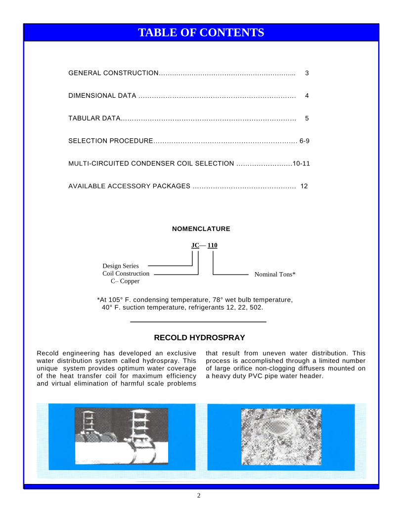
Recold engineering has developed an exclusivewater distribution system called hydrospray. Thisunique system provides optimum water coverageof the heat transfer coil for maximum efficiencyand virtual elimination of harmful scale problems
that result from uneven water distribution. Thisprocess is accomplished through a limited numberof large orifice non-clogging diffusers mounted ona heavy duty PVC pipe water header.
NOMENCLATURE
*At 105° F. condensing temperature, 78° wet bulb temperature,40° F. suction temperature, refrigerants 12, 22, 502.
GENERAL CONSTRUCTION……...……………………………………………... 3
DIMENSIONAL DATA ……………………………………………………………. 4
TABULAR DATA…………………………………………………………………… 5
SELECTION PROCEDURE………………………………………………………. 6-9
MULTI-CIRCUITED CONDENSER COIL SELECTION …………………….10-11
AVAILABLE ACCESSORY PACKAGES ………………………………………. 12
2
JC— 110
Design SeriesCoil Construction
C–CopperNominal Tons*
TABLE OF CONTENTS
RECOLD HYDROSPRAY

The Model JC Evaporative Condenser is a ruggedly built unit constructed to provide many years of durable, de-pendable service with minimal maintenance requirements. Quality materials and workmanship are a key factorin meeting this objective. Check the standard construction features shown to confirm this point.
Construction: The Evaporative Condenser sump pan is constructed of series 304 stainless steel and the casingpanels are constructed of heavy gauge, g-235 galvanized steel. The sump pan and casing panels are flangedoutward so that all the connecting fasteners are located outside the flooded section of the unit to help preventleaks in the unit and provides a more permanent watertight joint. To provide further protection from corrosion, useno welded joints below the water line. The unit is designed for a 30 psf on any projected area and ships in onepiece on a minimum 6” high stainless steel channel base to help in handling and installation of the unit..
3
GENERAL CONSTRUCTION
FAN MOTORSFan motors furnished as standard equipment are opendrip-proof type suitable for outdoor service. Motorshave a 1.15 service factor and are mounted on aheavy duty adjustable base located for easy access.
FAN GUARD SCREENSAll moving parts are protected with OSHA approvedgalvanized steel screens. Each guard is easily re-moved for access to the fan.
FAN SECTIONThe centrifugal fan is for-ward curved, statically anddynamically balanced andconstructed of galvanizedsteel. The fan housing has-curved inlet rings for effi-cient air entry and dis-charge into the pan. Fansare mounted on a solidsteel shaft coated to resistcorrosion. Heavy duty, pil-low block type, self-aligningball bearings are located ateach end of the fan shaft.
No intermediate bearingsare required
Extended lube lines aresupplied as standardequipment to allow servicing bearings without re-moval of fan guard screens.
WATER CIRCULATION PUMPWater circulation pump is a close coupled, bronze fit-ted centrifugal type with mechanical seal. Each pumpis factory mounted and piped. Standard motor is opendrip-proof suitable for outdoor service.
DRIFT ELIMINATORSEliminators are constructed of PVC assemblies in re-movable, easy to handle sections. Each section has athree break design allowing three changes in air flowand measure approximately 5 inches in depth. Theuse of durable PVC eliminates the corrosion problemsassociated with galvanized eliminators.
HEAT EXCHANGE COILCoil tube bundle is constructed of 5/8” copper tubing with stainless steel tube sheets and copper headers.The copper construction offers a noncorrosive coil for
extended service life.
ACCESS DOORSLarge rectangular ac-cess doors are strategi-cally located to provideaccess to both upperwater distribution systemand lower pan basin.The patented doors pro-vide a complete air andwater tight seal withoutthe use of gaskets orfasteners
WATER MAKE-UPWater make-up is providedby a solid brass float valvewith arm and float ball in-stalled in an external float
box. This allows easy observation of the water operat-ing level and maintenance of the valve with unit in op-eration.

JCMODEL
NO.
DIMENSIONS ARE SUBJECT TO CHANGEUSE CERTIFIED DRAWING FOR FABRICATION
ACCESS DOORS OVER-FLOWDRAIN
FPT
WATERSUPPLY
FPTFAR SIDE
A B C D F G H J K L M N TOP BOT. TOP BOT. P Q
20 81 76 31 84 32¾ 20½ - 6 53 13½ 2⅛ 1⅝ 1 1 0 0 3 ½
25-30 81 76 31 84 32¾ 20½ - 6 53 13½ 2⅛ 1⅝ 1 1 0 0 3 ½
38-46-5258 95¾ 76 36¾ 102 32¾ 20½ - 6 65 16 2½
2⅝1⅝1⅛ 1 1 0 0 3 ½
63-7280 116 77 45¼ 124 34¼ 20½ 51⅛ 6 76¾ 20½ 2⅝
3⅛1⅛2⅝ 1 1 1 1 3 ½
90-110120 139½ 89 55⅝ 144 37¾ 20 51⅛ 6 92 14½ 3⅛ 2⅝ 1 1 1 1(2) 3 ¾
135-165180-200 172¼ 93 66¾ 180 41¼ 20 71¾ 6 115 17½ 3⅛
(2)3⅛ 2⅝ 2 1 2 1(2) 3 1
240270-285 183½ 98 93½ 192 47 20 84½ 8 115 24 (2)3⅛ (2)2⅝ 2 1 2 1(2) 3 1¼
320350 208 98 93½ 217 47 20 96½ 8 139 24 (2) 3⅛
(4) 3⅛(2)3⅛(2)3⅛ 2 1 2 1(2) 3 1¼
375400 220 112(5) 100½ 225 67 19½ 80 10 139 (4) (4) 3⅛ (2)3⅛ 2 2 2 2 (2) 5 1¼
425450 244 112(5) 100½ 249 67 19½ 104 10 164 (4) (4) 3⅛ (2)3⅛ 2 2 2 2 (2) 5 1¼
475525 268 112(5) 100½ 273 67 19½ 128 10 188 (4) (o) 3⅛ (2)3⅛ 2 2 2 2 (2) 5 1¼
NEAR SIDE
NOTE: DISCHARGE DUCT FLANGE IS DIM. "C" Minus 3 Inches and "K" Minus 3 Inches.
3. Overall width of unit at base rail is C dimension plus 1 inch.
4. Consult factory for coil connection locations.
5. Maximum overall height at blower section is 118”
1.Add 6'/2 inches to height for subcooling coil.Add 6 inches for positive closure discharge damper.
2. An additional bottom access door. Installed on connec-tion end.
DIMENSIONAL DATA
4
Refer to certified drawings for final layout and supporting details.Specifications and dimensions are subject to change without notice.

MODELNO.
FANMOTOR
HP†
STD. FANMOTORFRAME
SIZE
SUMPHEATER
KW
SUMPCAPACITY
GAL.
AIRVOLUME
CFM
FANRPM
FANSIZE
COILFACESQ FT.
JC 20 2 145-T 1.5 32. 3200 960 18 7.4JC 25 2 145-T 1.5 43 5280 589 18 9.7JC 30 3 182-1 1.5 43 5900 796 18 9.7JC 38 3 182-T 2.6 64 7400 601 21 14.5JC 46 3 182.1 2.6 64 7000 636 21 14.5JC 52 5 184-T 2.6 64 8500 729 21 14.5JC 58 5 184-T 2.6 64 8300 740 21 14.5JC 63 3 182-T 2.6 95 9800 452 25 21.6JC 72 5 184-T 2.6 95 11800 523 25 21.6JC 80 7½ 213-T 2.6 95 13000 614 25 21.6JC 90 7½ 213-1 4.0 163 19000 413 31 32.5JC 110 10 215-T 4.0 163 20000 462 31 32.5JC 120 10 215-1 4.0 163 19500 476 31 32.5JC 135 10 215-1 5.5 248 26500 344 37 49.6JC 165 10 215-T 5.5 248 26000 356 37 49.6JC 180 10 215-T 5.5 248 24100 350 37 49.6JC 200 15 254-T 5.5 248 28400 385 37 49.6JC 240 20 256-T 8.0 374 37200 385 40 70.4JC 270 20 256-T 8.0 374 36600 385 40 70.4JC 285 25 284-T 8.0 374 39000 415 40 70.4JC 320 30 286-T 11.0 454 52300 415 40 85.5JC 350 30 286-T 11.0 454 50000 430 40 85.5JC 375 30 286-T 11.0 748 58300 252 49 92.5JC 400 30 286-T 11.0 748 61000 267 49 92.5JC 425 40 324-T 14.0 880 66000 256 49 108.9JC 450 40 324-T 14.0 880 69000 271 49 108.9JC 475 50 326-T 16.0 1012 76500 262 49 125.2JC 525 50 326-T 16.0 1012 80000 278 49 125.2
MODELNO
PUMPMOTOR
HP
SPRAYWATER
GPM
JCAPPROX. WEIGHT
R-22 R-404 SHIPPING OPERATINGJC 20 ½ 40 47 49 810 1230JC 25 ½ 40 40 41 910 1450JC 30 ½ 40 52 54 960 1500JC 38 ½ 50 61 64 1280 1940JC 46 ½ 50 81 84 1350 2010JC 52 ½ 50 91 95 1360 2020JC 58 ½ 50 99 103 1435 2395JC 63 ¾ 70 121 126 1940 2900JC 72 ¾ 70 138 144 1955 2915JC 80 ¾ 70 150 156 2075 3483JC 90 1 110 142 149 2955 4190JC 110 1 110 188 196 3090 4560JC 120 1 110 230 240 3305 4919JC 135 2 150 236 246 4355 6335JC 165 2 150 312 326 4610 6680JC 180 2 150 354 369 4860 7020JC 200 2 150 393 410 4880 7040JC 240 3 270 437 456 6675 10200JC 270 3 270 495 516 7045 10,900JC 285 3 270 522 544 7075 11200JC 320 3 325 455 478 7725 11900JC 350 3 325 484 580 8180 12900JC 375 5 365 599 604 9160 15700JC 400 5 365 748 753 9660 16300JC 425 5 400 705 710 10070 17700JC 450 5 400 881 888 10660 18500JC 475 5 450 817 824 11005 19800JC 525 5 450 1015 1022 11700 20700
REFRIGERANT CHARGE (LBS.)
For static pressure from ¼ to ½ ESP, use next size larger motor.
Specifications and dimensions are subject to change without notice
MODEL JC (COPPER COIL) 20 THRU 525
TABULAR DATA
5

The Model JC unit selection may be obtained by using one of two methods presented. The simplest method isthat based on evaporator ton load and is intended for open type reciprocating compressor applications.
The second method given is selected by total heat of rejection which provides a more comprehensive and accu-rate procedure. In addition to selecting units for open type reciprocating compressor systems, this method maybe applied to selecting condensers for systems with centrifugal, hermetic reciprocating or rotary screw typecompressors.
EVAPORATOR TON METHOD
The JC condenser model numbers (Table No. 1) areequal to the unit capacity in evaporator tons at stan-dard conditions for refrigerant 12, 22 and 502 at 105°F. condensing temp., 40° F. suction temp., and 78°F. wet bulb temperature.
When selecting a unit for non-standard conditions, en-ter Table 3, Page 7, to select capacity correction fac-tors and multiply times the system evaporator ton load.Select the standard unit model number which isgreater than or equal to this product.
From Table 5 Capacity Factor at 75° F. wet bulb and105° F. Cond. = .93.
EXAMPLE
Given: Evaporator Loan, R-22 81 TonsEntering Air Wet Bulb 72° F .
Condensing Temp. 105° FSuction Temp. 30° F .
Determine Condenser Selection:
From Table 3 Capacity Factor at 72° F . wet bulb and105° F. Cond. = .86.
Suction Pressure Capacity Factor at 30° F = 1.03.
81 Tons x .86 x 1.03 = 71.7 corrected tons
Select Model JC-72 since its model number is greaterthan the design corrected evaporator load.
STANDARD CONDITIONSTABLE NO. 1(Copper Coil)
MODEL JC NO. & CAPACITY¹
20 25 30 38 46 52 58 63 72 80 90 110 120 135 165 180 200 240 270 285 320 350 375 400 425 450 475 525
¹Based on standard conditions for refrigerants R-12, R-22 and R-502 at 105º cond., 40º suction, 78º W.B.2Model JC is not applicable for ammonia systems.
SELECTION PROCEDURE
6

Cond. Press(PSIG)
Cond.Temp.(°F)
WET BULB TEMPERATURE (°F)
R12 R22 50 55 60 65 68 70 72 75 78 80 85 9091.8 155.7 85 1.05 1.16 1.33 1.61 1.87 1.98 2.26 2.8099.8 168.4 90 .90 .98 1.11 1.28 1.43 1.54 1.72 1.96 2.33 2.70108.3 181.8 95 .78 .85 .93 1.04 1.12 1.18 1.28 1.39 1.59 1.75 2.50117.2 195.9 100 .70 .75 .81 .88 .93 .97 1.03 1.11 1.22 1.32 1.70 2.53126.6 210.8 105 .63 .66 .70 .76 .79 .83 .86 .93 1.00 1.05 1.27 1.67136.4 226.4 110 .57 .60 .63 .67 .70 .72 .75 .80 .85 .89 1.02 1.26.
146.8 242.7 115 .54 .57 .60 .63 .64 .66 .69 .73 .75 .84 .99157.7 259.9 120 .53 .55 .56 .58 .60 .63 .65 .70 .81
EVAPORATOR CAPACITY FACTORSRefrigerants 12, 22, 500 and 502—(Non Standard Conditions)
TABLE NO. 3
SUCTION PRESSURE CAPACITY FACTORS0.6 4.5 9.2 14.6 21.0 28.5 37.0 46.710.2 16.5 24.0 32.8 43.0 54.9 68.5 84.015.5 22.8 31.2 41.1 52.5 65.4 80.2 96.9
Suction Temp. ° F. -20 -10 0 +10 +20 +30 +40 +50Capacity Factor 1.32 1.23 1.17 1.11 1.07 1.03 1.00 .97
Suction R-12Pressure R-22PSIG R-502
EVAP LOAD X FACTORS = CORRECTED TONS
7
SELECTION PROCEDURE

HEAT OF REJECTION METHOD
Many times, the specification for an evaporative con-denser will be expressed in "Total Heat Rejection" (THR)at the condenser, rather than the net refrigeration effectat the evaporator. Basically, total heat rejection is thesum of the compressor capacity in BTUH and the heatcorresponding to the brake horsepower (BHP) in BTUHfor open type compressors or to the kilowatt (KW) inputin BTUH for hermetic compressors.
Where the "Total Heat Rejection" is not specified, it canbe readily calculated by using the following formulas:
Open Type Compressors:
THR = Compressor Evaporator Capacity (BTUH) +Compressor BHP x 2545
Hermetic Compressor
THR = Compressor Evaporator Capacity (BTUH) +Compressor KW x 3413
The selection procedure for this method is similar to thatgiven for the evaporator ton method once the heat of re-jection requirements are known. Enter Page 9, Table 5and select a capacity factor per design condensing tem-
perature and entering air wet bulb. Multiply the factortimes the system total heat of rejection. Select the unitmodel from Table 4 whose heat of rejection is greaterthan or equal to this product.
EXAMPLE:Given:
Compressor Evaporator Capacity 51 TonsWet Bulb Temperature 75° F.Condensing Temp. 105° F.Type Compressor Hermetic R-22Compressor KW Input 49.0 KW
Determine Condenser Selection:Heat of Rejection
51 Tons x 12,000 = 612,000 BTUH49.0 KW x 3413 =167,000 BTUH
Total Heat Rejection =779,000 BTUH
From Table 5 Capacity Factor at 72° F. wet bulb and 105°F. Cond. = .86.
779,000 BTUH x .93 = 724,470 BTUHapprox. (724.5 MBH).
Select Model JC-52 condenser since its nominal totalheat rejection is greater than or equal to the requiredTHR.
MODELNO.
HEATREJ.
MBH(1)
J C 20 294.0JC 25 367.5J C 30 441.0JC 38 558.6J C 46 676.2J C 52 764.4J C 58 852.6J C 63 926.1JC 72 1058.4JC 80 1176.0J C 90 1323.0JC 110 1617.0JC 120 1764.0
MODELNO.
HEATREJ.
MBH(l)
JC 135 1984.5JC 165 2425.5J C 180 2646.0JC 200 2940.0J C 240 3528.0J C 270 3969.0J C 285 4189.5J C 320 4689.3J C 350 5203.8J C 375 5513.0JC 400 5880.0JC 425 6336.0JC 450 6762.0JC 475 7159.0JC 525 7644.0
(1)Based on standard conditions for refrigerants12, 22, and 502, 105 C̊ond., 40 ̊Suction, 78̊ W.B.
TABLE NO. 4
MODEL JC(Copper Coil)
NOMINALTOTAL HEAT REJECTION –MBH
SELECTION PROCEDURE
8
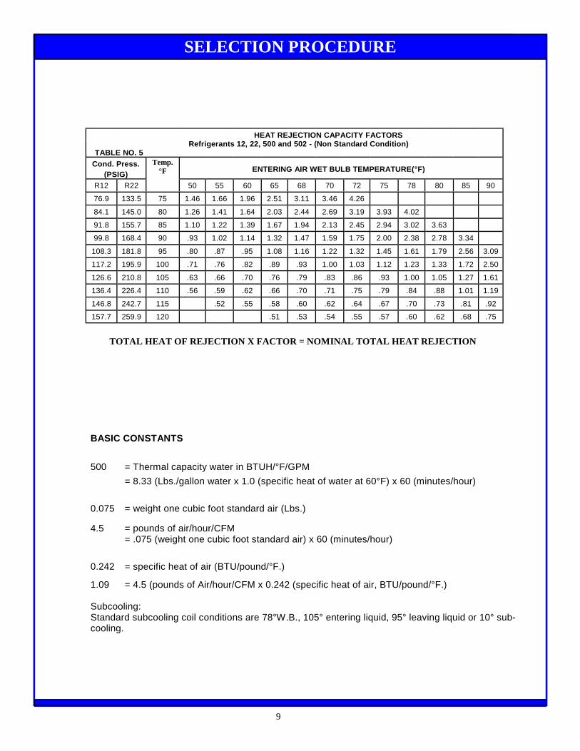
HEAT REJECTION CAPACITY FACTORSRefrigerants 12, 22, 500 and 502 - (Non Standard Condition)
TABLE NO. 5Cond. Press.
(PSIG)ENTERING AIR WET BULB TEMPERATURE(°F)
R12 R22 50 55 60 65 68 70 72 75 78 80 85 90
76.9 133.5 75 1.46 1.66 1.96 2.51 3.11 3.46 4.26
84.1 145.0 80 1.26 1.41 1.64 2.03 2.44 2.69 3.19 3.93 4.02
91.8 155.7 85 1.10 1.22 1.39 1.67 1.94 2.13 2.45 2.94 3.02 3.63
99.8 168.4 90 .93 1.02 1.14 1.32 1.47 1.59 1.75 2.00 2.38 2.78 3.34
108.3 181.8 95 .80 .87 .95 1.08 1.16 1.22 1.32 1.45 1.61 1.79 2.56 3.09
117.2 195.9 100 .71 .76 .82 .89 .93 1.00 1.03 1.12 1.23 1.33 1.72 2.50
126.6 210.8 105 .63 .66 .70 .76 .79 .83 .86 .93 1.00 1.05 1.27 1.61
136.4 226.4 110 .56 .59 .62 .66 .70 .71 .75 .79 .84 .88 1.01 1.19
146.8 242.7 115 .52 .55 .58 .60 .62 .64 .67 .70 .73 .81 .92
157.7 259.9 120 .51 .53 .54 .55 .57 .60 .62 .68 .75
Temp.°F
BASIC CONSTANTS
500 = Thermal capacity water in BTUH/°F/GPM
= 8.33 (Lbs./gallon water x 1.0 (specific heat of water at 60°F) x 60 (minutes/hour)
0.075 = weight one cubic foot standard air (Lbs.)
4.5 = pounds of air/hour/CFM= .075 (weight one cubic foot standard air) x 60 (minutes/hour)
0.242 = specific heat of air (BTU/pound/°F.)
1.09 = 4.5 (pounds of Air/hour/CFM x 0.242 (specific heat of air, BTU/pound/°F.)
Subcooling:Standard subcooling coil conditions are 78°W.B., 105° entering liquid, 95° leaving liquid or 10° sub-cooling.
TOTAL HEAT OF REJECTION X FACTOR = NOMINAL TOTAL HEAT REJECTION
SELECTION PROCEDURE
9

Model JC Evaporative Condensers are designedfor applications where a multiple of refrigeration sys-tems are connected to a single unit. The Model JCEvaporative Condensers can be furnished from thefactory having the condenser coil divided into individ-ual refrigerant circuits, each sized to meet a specifiedcapacity. Each circuit is sup-plied with a hot gas inletconnection and liquid outlet connection, each taggedfor identification.The procedure for selecting a multi-circuited con-denser coil is described in the "Selection Example", asoutlined below. For circuit identification purposes it isrequired that circuits be arranged in numerical se-quence. The connections for the individual circuits, willbe numbered at the factory, from left to right when fac-ing connection end of unit, with the number 1 circuitbeing on the extreme left.
Selection Example:Given:Condensing Temperature 100° F.Entering Air Wet Bulb Temp. 72° F.
Ten individual suction cooled hermetic compressorsoperating at suction temperatures and compressor ca-pacities, as shown in the tabulation below.
Procedure1. Tabulate data in Columns 1, 2 and 3, making sure
circuits are in correct numerical sequence.2. From Table No. 7, "Hermetic Compressors," select
Evaporator Temperature Capacity Factor applicableto each Suction Temperature listed in Column 2and tabulate in Column 4.
3. From Table No. 8, select "Condenser Capacity Co-version Factor" applicable to the design condensingtemperature and the design entering air wet bulbtemperature and tabulate in Column 5.
4. Multiply figures in Columns 3, 4 and 5 for each cir-cuit, and tabulate in Column 6.
5. Add all the capacities in Column 6, to arrive at theTotal Adj. BTUH to Nominal required and use thetotal to select the proper size condenser.
Selection:The total Adj. BTUH to Nominal capacity, for the four re-frigeration systems, of 994,900 BTUH, Table No. 6shows the smallest unit that will meet the requirement isModel JC-72 with a THR of 1,058,400 BTUH.To determine the number of tube circuits required foreach sequence number circuit divide Column 6 by Col-umn 7, for each circuit and tabulate in Column 8. If thedecimal part of the tube circuit requirement is less than .3,drop the decimal and enter the whole number in Column9. If the decimal part is equal to or greater than .2, roundoff to the next higher whole number and enter in Col-umn 9.The "Tabulation Sample" shows 33 tube circuits are re-quired, for this example, and Table 6 shows that ModelJC-72 has 33 tube circuits available, therefore, is theproper unit selection.
NOTE:If the summation of the number of tube circuits as-signed to the individual circuits is less than the totalnumber of tube circuits available in the unit, by inspec-tion, add enough tubes to effect a balance. If the sum-mation of the number of tube circuits assigned to the in-dividual circuits is greater than the total number of tubecircuits available in the unit by inspection, deleteenough tubes to effect a balance. However, if such re-duction causes more than a 10 percent reduction in anyof the circuits, go to the next larger unit size and re-assign tube circuits to give adequate capacity to everycircuit.
1 2 3 X 4 X 5 = 6 / 7 = 8 9
CircuitNo.
SuctionTemp.
°F
Comp.Capacity
BTUH x
EvapTemp.Cap.
Conver.FactorTable
11 x
Cond.Cap.
Conver.FactorTable
12 =
Adj.BTUH
ToNominal /
CapacityPer TubeCircuit
Table 10 =
No. ofCircuitsrequired
No. ofCircuits
Used
1 -20 108,600 x 1.79 x 1.03 = 200,200 / 32,070 = 6.24 7
2 +10 90,700 x 1.51 x 1.03 = 141,100 / 32,070 = 4.40 5
3 +20 185,400 x 1.45 x 1.03 = 276,900 / 32,070 = 8.63 9
4 +40 275,000 x 1.33 x 1.03 = 376,700 / 32,070 = 11.75 12
994,900 33
TABULATION EXAMPLE
10
MULTI-CIRCUIT CONDENSER COIL SELECTION
EVAP. TEMP.°F. - 40 -30 - 25 - 20 -15 -10 -5 0 5 10 15 20 25 30 35 40 45 50Open Compressors 1.75 1.65 1.62 1.59 1.55 1.53 1.50 1.47 1.44 1.40 1.37 1.35 1.32 1.30 1.28 1.26 1.24 1.22Hermetic Compressors 2.02 1.90 1.85 1.79 1.74 1.69 1.65 1.61 1.57 1.51 1.48 1.45 1.40 1.36 1.34 1.33 1.32 1.31
TABLE NO. 7 EVAPORATIVE TEMP. CAPACITY CONVERSION FACTOR

ModelNo.
Total Heat Rejection CapacityAt 105°F. Cond. Temp., 78°F. W. B. Temp.
Refrigerants 12, 22 and 502
Total Unit BTUH BTUH Per Tube Circuit
JC 20 19 294,000 15,470JC 25 21 367,500 17,500JC 30 21 441,000 21,000JC 38 26 558,600 21,485JC 46 26 676,200 26,000JC 52 26 764,400 29,400JC 58 26 852,600 32,790JC 63 33 926,100 28,060JC 72 33 1,058,400 32,070JC 80 33 1,176,000 35,636JC 90 82 1,323,000 16,130JC 110 82 1,617,000 19,220JC 120 82 1,764,000 21,510JC 135 100 1,984,500 19,845JC 165 100 2,425,500 24,255JC 180 100 2,646,000 26,460JC 200 100 2,940,000 29,400JC 240 140 3,528,000 25,200JC 270 140 3,969,000 28,350JC 285 140 4,189,500 29,925JC 320 140 4,689,300 33,495JC 350 140 5,203,800 37,170JC 375 152 5,513,000
No. of TubeCircuits Available
JC 400 152 5,880,00036,27038,680
JC 425 152 6,336,000 41,680JC 450 152 6,762,000 44,490JC 475 152 7,159,000 47,100JC 525 152 7,644,000 50,290
CondensingPressure(PSIG) .
Cond.Temp.
°F
WET BULB TEMPERATURE (°F)
R12 R22 50 55 60 65 68 70 72 75 78 80 85 9076.9 133.5 75 1.46 1.66 1.96 2.51 3.11 3.46 4.2684.1 145.0 80 1.26 1.41 1.64 2.03 2.44 2.69 3.19 3.93 4.0291.8 155.7 85 1.10 1.22 1.39 1.67 1.94 2.13 2.45 2.94 3.02 3.6399.8 168.4 90 .93 1.02 1.14 1.32 1.47 1.59 1.75 2.00 2.38 2.78 3.34
108.3 181.8 95 .80 .87 .95 1.08 1.16 1.22 1.32 1.45 1.61 1.79 2.56 3.09117.2 195.9 100 .71 .76 .82 .89 .93 1.00 1.03 1.12 1.23 1.33 1.72 2.50126.6 210.8 105 .63 .66 .70 .76 .79 .83 .86 .93 1.00 1.05 1.27 1.61136.4 226.4 110 .56 .59 .62 .66 .70 .71 .75 .79 .84 .88 1.01 1.19146.8 242.7 115 .49 .52 .55 .58 .60 .62 .64 .67 .70 .73 .81 .92157.7 259.9 120 .41 .45 .48 .51 .53 .54 .55 .57 .60 .62 .68 .75
CONDENSER CAPACITY CONVERSION FACTORSRefrigerants 12, 22, and 502
TABLE NO. 8
NOTE: Model JC 240 through 525 coil arrangement provides two equal circuits as standard.
TABLE NO. 6 MODEL JC (Copper Coil)
11
MULTI-CIRCUITED CONDENSER COIL SELECTION
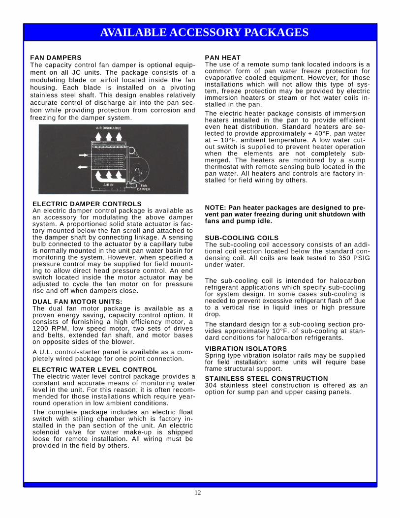
FAN DAMPERSThe capacity control fan damper is optional equip-ment on all JC units. The package consists of amodulating blade or airfoil located inside the fanhousing. Each blade is installed on a pivotingstainless steel shaft. This design enables relativelyaccurate control of discharge air into the pan sec-tion while providing protection from corrosion andfreezing for the damper system.
ELECTRIC DAMPER CONTROLSAn electric damper control package is available asan accessory for modulating the above dampersystem. A proportioned solid state actuator is fac-tory mounted below the fan scroll and attached tothe damper shaft by connecting linkage. A sensingbulb connected to the actuator by a capillary tubeis normally mounted in the unit pan water basin formonitoring the system. However, when specified apressure control may be supplied for field mount-ing to allow direct head pressure control. An endswitch located inside the motor actuator may beadjusted to cycle the fan motor on for pressurerise and off when dampers close.
DUAL FAN MOTOR UNITS:The dual fan motor package is available as aproven energy saving, capacity control option. Itconsists of furnishing a high efficiency motor, a1200 RPM, low speed motor, two sets of drivesand belts, extended fan shaft, and motor baseson opposite sides of the blower.
A U.L. control-starter panel is available as a com-pletely wired package for one point connection.
ELECTRIC WATER LEVEL CONTROLThe electric water level control package provides aconstant and accurate means of monitoring waterlevel in the unit. For this reason, it is often recom-mended for those installations which require year-round operation in low ambient conditions.The complete package includes an electric floatswitch with stilling chamber which is factory in-stalled in the pan section of the unit. An electricsolenoid valve for water make-up is shippedloose for remote installation. All wiring must beprovided in the field by others.
PAN HEATThe use of a remote sump tank located indoors is acommon form of pan water freeze protection forevaporative cooled equipment. However, for thoseinstallations which will not allow this type of sys-tem, freeze protection may be provided by electricimmersion heaters or steam or hot water coils in-stalled in the pan.The electric heater package consists of immersionheaters installed in the pan to provide efficienteven heat distribution. Standard heaters are se-lected to provide approximately + 40°F. pan waterat –10°F. ambient temperature. A low water cut-out switch is supplied to prevent heater operationwhen the elements are not completely sub-merged. The heaters are monitored by a sumpthermostat with remote sensing bulb located in thepan water. All heaters and controls are factory in-stalled for field wiring by others.
NOTE: Pan heater packages are designed to pre-vent pan water freezing during unit shutdown withfans and pump idle.
SUB-COOLING COILSThe sub-cooling coil accessory consists of an addi-tional coil section located below the standard con-densing coil. All coils are leak tested to 350 PSIGunder water.
The sub-cooling coil is intended for halocarbonrefrigerant applications which specify sub-coolingfor system design. In some cases sub-cooling isneeded to prevent excessive refrigerant flash off dueto a vertical rise in liquid lines or high pressuredrop.
The standard design for a sub-cooling section pro-vides approximately 10°F. of sub-cooling at stan-dard conditions for halocarbon refrigerants.
VIBRATION ISOLATORSSpring type vibration isolator rails may be suppliedfor field installation: some units will require baseframe structural support.
STAINLESS STEEL CONSTRUCTION304 stainless steel construction is offered as anoption for sump pan and upper casing panels.
12
AVAILABLE ACCESSORY PACKAGES