Embed Size (px)
Citation preview

8/7/2019 RECIPROCITY THEOREM (Labsheet 3)
http://slidepdf.com/reader/full/reciprocity-theorem-labsheet-3 1/6
K ATHMANDU UNIVERSITY SCHOOL OF E NGINEERING
DEPARTMENT OF ELECTRICAL & ELECTRONICS ENGINEERING
LAB R EPORT 3
ANTENNA AND PROPAGATION
RECIPROCITY THEOREM
By:
Kushal Pradhan
EE-Communication
Roll no: 41015
Submitted to:
Ms. Manya Gautam,
Department of Electrical and Electronics,
Kathmandu University,
Dhulikhel
Date: 21st November, 2010
8/7/2019 RECIPROCITY THEOREM (Labsheet 3)
http://slidepdf.com/reader/full/reciprocity-theorem-labsheet-3 2/6
Objective: To demonstrate that the transmitting and receiving radiation patterns of an antenna are
equal and hence confirm the reciprocity theorem of antennas
Equipments used:
i. Yagi and Dipole antenna.
ii. Antenna transmitter, receiver and stepper motor controller.iii. Antenna tripod and stepper tripod with connecting cables, measuring
Tape
Background:
A Yagi-Uda Antenna, commonly known simply as a Yagi antenna or Yagi, is adirectional antenna system consisting of an array of a dipole and additional closely coupled
parasitic elements. A parasitic element is an element that is not directly connected to the feedline. Parasitic elements are used for the purpose of obtaining directional power gain. Generally,
parasitic elements can be classified as either directors or reflectors; hence they work in oppositeways.
The dipole in the array is driven, and another element, typically 5% longer, effectivelyoperates as a reflector. Other parasitic elements shorter than the dipole may be added in front of
the dipole and are referred to as directors. This arrangement increases antenna directionality andgain in the preferred direction over a single dipole.
Directional antennas such as the Yagi-Uda are commonly referred to as beam antennasor high-gain antennas (particularly for transmitting).
A dipole antenna is a radio antenna that can be made by a simple wire, with a center-
fed driven element. The current amplitude on such an antenna decreases uniformly frommaximum at the center to zero at the ends.
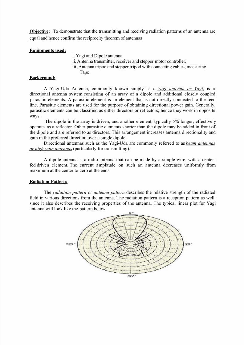
Radiation Pattern:
The radiation pattern or antenna pattern describes the relative strength of the radiated
field in various directions from the antenna. The radiation pattern is a reception pattern as well,since it also describes the receiving properties of the antenna. The typical linear plot for Yagi
antenna will look like the pattern below.
8/7/2019 RECIPROCITY THEOREM (Labsheet 3)
http://slidepdf.com/reader/full/reciprocity-theorem-labsheet-3 3/6
The radiation pattern in the region close to the antenna is not the same as the pattern at largedistances. The term near-field refers to the field pattern that exists close to the antenna, while the
term far-field refers to the field pattern at large distances. The far-field is also called the radiationfield, and is what is most commonly of interest. Ordinarily, it is the radiated power that is of
interest, and so antenna patterns are usually measured in the far-field region. For pattern
measurement it is important to choose a distance sufficiently large to be in the far-field, well outof the near-field. The minimum permissible distance depends on the dimensions of the antennain relation to the wavelength. The accepted formula for this distance is:
R min = (2d2)/P
Where, R min is the minimum distance from the antenna, d is the largest dimension of the antenna,
and P is the wavelength.
Reciprocity Theorem:
If an emf is applied to the terminals of an antenna A and the current measured at the terminals of
another antenna B, then an equal current (in both amplitude and phase) will be obtained at the
terminals of A if the same emf is applied to the terminals of antenna B.
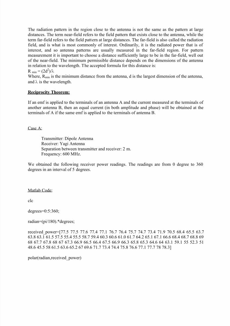
Case A:
Transmitter: Dipole AntennaReceiver: Yagi Antenna
Separation between transmitter and receiver: 2 m.Frequency: 600 MHz.
We obtained the following receiver power readings. The readings are from 0 degree to 360
degrees in an interval of 5 degrees.
Matlab Code:
clc
degrees=0:5:360;
radian=(pi/180).*degrees;
received_power=[77.5 77.5 77.6 77.4 77.1 76.7 76.4 75.7 74.7 73.4 71.9 70.5 68.4 65.5 63.763.8 63.1 61.5 57.5 55.4 55.5 58.7 59.4 60.3 60.6 61.0 61.7 64.2 65.1 67.1 66.6 68.4 68.7 68.8 69
68 67.7 67.8 68 67 67.3 66.9 66.5 66.4 67.5 66.9 66.3 65.8 65.3 64.6 64 63.1 59.1 55 52.3 5148.6 45.5 58 61.5 63.6 65.2 67 69.6 71.7 73.4 74.4 75.8 76.6 77.1 77.7 78 78.3]
polar(radian,received_power)
8/7/2019 RECIPROCITY THEOREM (Labsheet 3)
http://slidepdf.com/reader/full/reciprocity-theorem-labsheet-3 4/6
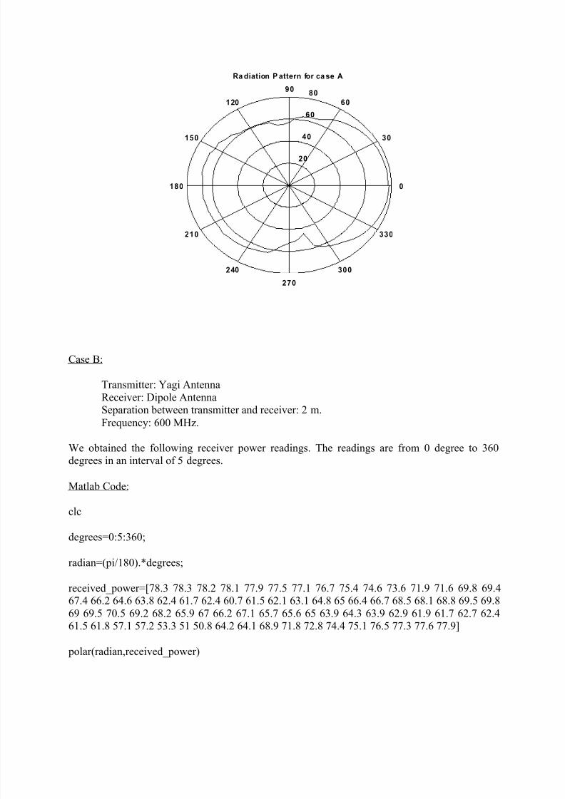
Case B:
Transmitter: Yagi Antenna
Receiver: Dipole AntennaSeparation between transmitter and receiver: 2 m.
Frequency: 600 MHz.
We obtained the following receiver power readings. The readings are from 0 degree to 360degrees in an interval of 5 degrees.
Matlab Code:
clc
degrees=0:5:360;
radian=(pi/180).*degrees;
received_power=[78.3 78.3 78.2 78.1 77.9 77.5 77.1 76.7 75.4 74.6 73.6 71.9 71.6 69.8 69.467.4 66.2 64.6 63.8 62.4 61.7 62.4 60.7 61.5 62.1 63.1 64.8 65 66.4 66.7 68.5 68.1 68.8 69.5 69.8
69 69.5 70.5 69.2 68.2 65.9 67 66.2 67.1 65.7 65.6 65 63.9 64.3 63.9 62.9 61.9 61.7 62.7 62.461.5 61.8 57.1 57.2 53.3 51 50.8 64.2 64.1 68.9 71.8 72.8 74.4 75.1 76.5 77.3 77.6 77.9]
polar(radian,received_power)
20
40
60
80
30
210
60
240
90
270
120
300
150
330
180 0
Ra diation P attern for ca se A
8/7/2019 RECIPROCITY THEOREM (Labsheet 3)
http://slidepdf.com/reader/full/reciprocity-theorem-labsheet-3 5/6
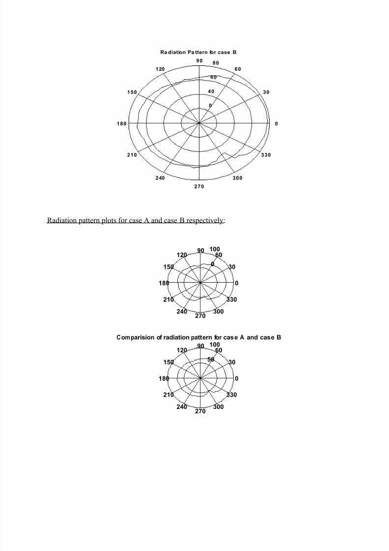
Radiation pattern plots for case A and case B respectively:
20
40
60
80
30
210
60
240
90
270
120
300
150
330
180 0
Ra diation Pa ttern for case B
50
100
30
210
60
240
90
270
120
300
150
330
180 0
50
100
30
210
60
240
90
270
120
300
150
330
180 0
Comparision of radiation pattern for case A and case B
8/7/2019 RECIPROCITY THEOREM (Labsheet 3)
http://slidepdf.com/reader/full/reciprocity-theorem-labsheet-3 6/6
The reflection from the walls and other obstacles, interference et cetera, had influenced thereadings. Owing to these limitations we have not been able to get the radiation pattern showing
distinct front, back and side lobes. Despite of these intrinsic constraints, we can infer from thecomparative plots, that the plots are similar.
Inference:
Referring to the consequence of reciprocity theorem that, transmitting and receiving pattern of anantenna are the same, we have shown that the transmitting and receiving pattern of Yagi antenna
is same. So, this confirms the reciprocity theorems of antennas.


![5 different superposition principles with/without test ...vixra.org/pdf/1811.0396v2.pdfcorrelation reciprocity theorem[7]. It can be proven that the cross correlation reciprocity theorem](https://img.pdfslide.us/doc/110x75/5ea307e43ad85b64472c4bb0/5-different-superposition-principles-withwithout-test-vixraorgpdf1811-correlation.jpg)