Embed Size (px)
Citation preview
Reciprocating positivedisplacement pumpsTechnical basics and applications
LEWA GmbH
2 3
Reciprocating positivedisplacement pumpsTechnical basics and applications
4 5
1 Introduction ���������������������������������������������������������������������� 81�1 Foreword ��������������������������������������������������������������������������������������������������������� 81�2 Pump technology systems ������������������������������������������������������������������������������� 81�2�1 Centrifugal pumps ������������������������������������������������������������������������������������������� 91�2�2 Rotary positive displacement pumps �������������������������������������������������������������� 101�2�3 Reciprocating positive displacement pumps ��������������������������������������������������� 121�2�4 Comparison of the different pump types ������������������������������������������������������� 151�3 Application areas of diaphragm pumps���������������������������������������������������������� 161�4 Design of metering pumps ���������������������������������������������������������������������������� 181�4�1 Design formulas��������������������������������������������������������������������������������������������� 181�4�2 Design criteria ����������������������������������������������������������������������������������������������� 19
2 Technology ��������������������������������������������������������������������� 232�1 Modularity of reciprocating positive displacement pumps ������������������������������ 232�1�1 Pump construction kit ����������������������������������������������������������������������������������� 232�1�2 An overview of construction kit components ������������������������������������������������ 252�2 Drive and drive unit components for metering pumps ����������������������������������� 292�2�1 Drives and motors ����������������������������������������������������������������������������������������� 302�2�2 Linear drive – Direct drives for reciprocating pumps��������������������������������������� 302�2�3 Rotating pump drives ������������������������������������������������������������������������������������ 332�2�3�1 Electromotive drives �������������������������������������������������������������������������������������� 332�2�3�2 Frequency inverter ����������������������������������������������������������������������������������������� 382�2�3�3 Other motor drives ���������������������������������������������������������������������������������������� 412�2�4 Gear drives ���������������������������������������������������������������������������������������������������� 422�2�5 Drive units ����������������������������������������������������������������������������������������������������� 432�2�5�1 Spring-cam drive units �����������������������������������������������������������������������������������442�2�5�2 Wobble plate and swash plate drive units ������������������������������������������������������462�2�5�3 Crank rocker drive units with adjustable swing arm bearing ��������������������������482�2�5�4 Rocker arm drive units with pivot adjustment of the coupling ������������������������ 492�2�5�5 Cross crank drive units ����������������������������������������������������������������������������������� 502�2�5�6 Straight crank drive units ������������������������������������������������������������������������������� 51
Content
Copyright 2018 LEWA GmbH� All rights reserved�
This publication is protected by the Copyright Protection Law and international agreements� No part of this publication is allowed to be reproduced in any form or using any means unless LEWA GmbH has first granted written consent�
DisclaimerThe contents of this manual have been created with the utmost care to ensure they are correct� However, LEWA GmbH shall assume no liability for damage, regardless of whether such damage has resulted directly, indirectly, inadvertently or consequently from using the contents of this manual or relying on them being correct�
Typesetting and layout: markenkrieger e� K�Technical editing: TechniTeX®
Translation: oneword GmbH
Edition 1, 2018
6 7
4�2�2�3 Fluid mechanics and design of piping ���������������������������������������������������������� 1214�2�2�4 Methods for pressure pulsation damping ����������������������������������������������������� 1294�2�2�5 Pulsation analyses ���������������������������������������������������������������������������������������� 1344�3 Instrumentation and control engineering ����������������������������������������������������� 1374�3�1 Instrumentation ������������������������������������������������������������������������������������������� 1374�3�2 Process control �������������������������������������������������������������������������������������������� 1384�3�3 Condition monitoring systems ��������������������������������������������������������������������� 1414�3�4 Synchronization ������������������������������������������������������������������������������������������� 1474�4 Control of fluid kinematics ��������������������������������������������������������������������������� 149
5 Economic efficiency ������������������������������������������������������� 156
6 Applications �������������������������������������������������������������������1616�1 Oil & Gas – Methanol injection �������������������������������������������������������������������� 1616�2 Odorization – Gas odorization in the natural gas distribution grid ��������������� 1626�3 Refineries – Production of biofuels �������������������������������������������������������������� 1636�4 Petrochemicals – Silane metering ����������������������������������������������������������������� 1646�5 Chemicals – Caustic soda production ���������������������������������������������������������� 1666�6 Plastics – Precise metering of blowing agents in extruders ��������������������������� 1676�7 Personal care – Supercritical fluids in the cosmetics, food and pharmaceutical sectors ����������������������������������������������������������������� 1686�8 Food – Production of spreadable butter ������������������������������������������������������ 1696�9 Energy – Flue gas cleaning by sulfur metering ���������������������������������������������� 1706�10 Pharmaceuticals – Chromatography ������������������������������������������������������������� 1716�11 Research and science – CO₂ cooling ������������������������������������������������������������ 1736�12 Drive technology – Continuous metering of micro flows ������������������������������ 174
Glossary & Abbreviations ����������������������������������������������������������176
List of figures �������������������������������������������������������������������������� 183
Formula directory �������������������������������������������������������������������� 186
Reference list ��������������������������������������������������������������������������� 188
Index �������������������������������������������������������������������������������������� 190
2�2�6 Stroke adjustment of the drive units �������������������������������������������������������������542�2�6�1 Manual stroke adjustment �����������������������������������������������������������������������������542�2�6�2 Electric stroke adjustment ������������������������������������������������������������������������������542�2�6�3 Pneumatic stroke adjustment ������������������������������������������������������������������������� 562�2�6�4 Stroke length adjustment vs� stroke frequency adjustment ���������������������������� 572�3 Pump head technology ���������������������������������������������������������������������������������� 582�3�1 Evolutionary steps ����������������������������������������������������������������������������������������� 582�3�2 Hydraulic valves ���������������������������������������������������������������������������������������������682�4 Design examples of different pump heads ����������������������������������������������������� 722�4�1 Plunger pump heads �������������������������������������������������������������������������������������� 732�4�2 Directly driven diaphragm pump heads ��������������������������������������������������������� 742�4�2�1 Air-operated diaphragm pumps ��������������������������������������������������������������������� 742�4�2�2 Mechanically driven diaphragm pump heads ������������������������������������������������� 752�4�3 Hydraulically driven diaphragm pump heads �������������������������������������������������� 762�4�3�1 Hydraulically driven polymer diaphragm pump heads ������������������������������������ 772�4�3�2 Hydraulically driven metal diaphragm pump heads ����������������������������������������802�4�3�3 Special designs for hydraulically driven diaphragm pump heads ��������������������� 832�5 Fluid valves ���������������������������������������������������������������������������������������������������� 852�5�1 Basic design of valves ������������������������������������������������������������������������������������862�5�2 Special design of valves ���������������������������������������������������������������������������������882�6 Diaphragms and diaphragm monitoring ��������������������������������������������������������90
3 Directives, standards, and specifications ��������������������������� 963�1 Directives and standards in Europe ����������������������������������������������������������������963�2 Explosion protection ��������������������������������������������������������������������������������������963�3 Eco-friendly design and efficiency ratings of electric motor drives �����������������983�4 Standards outside Europe ������������������������������������������������������������������������������993�5 API 674 3rd edition: Reciprocating Positive Displacement Pumps ����������������� 1003�5�1 Performance test in accordance with ANSI/HI 6�6-2015 ������������������������������� 1013�5�2 NPIPR/NPSHR Test ��������������������������������������������������������������������������������������� 1023�5�3 Sonic emissions in accordance with ISO 3744 ���������������������������������������������� 1023�6 API 675 3rd edition: Controlled Volume Positive Displacement Pumps ��������� 1023�7 NORSOK ������������������������������������������������������������������������������������������������������ 1053�8 NACE ����������������������������������������������������������������������������������������������������������� 1063�9 Company and project specifications ������������������������������������������������������������ 107
4 Integrating metering pumps into the overall system �������� 1084�1 P&ID ������������������������������������������������������������������������������������������������������������ 1084�2 Hydraulic and mechanical integration ���������������������������������������������������������� 1094�2�1 Fluid properties ��������������������������������������������������������������������������������������������1104�2�2 The basics of piping calculation ��������������������������������������������������������������������1164�2�2�1 Operating criteria �����������������������������������������������������������������������������������������1164�2�2�2 NPSH/NPIP ���������������������������������������������������������������������������������������������������118
8 9
1 IntroductionIn this chapter, you will get an overview of the most common pump types and their designs. The operating principles as well as the advantages and disadvan-tages of each pump type and its fields of application are presented. This chapter will cover the applications of diaphragm pumps in greater detail. The basic formu-las and important parameters for designing reciprocating positive displacement pumps are specified.
1.1 Foreword
The pump is one of mankind’s most important inventions� The Ancient Greeks and Ro-mans even used reciprocating pumps to convey water� As early as the High Middle Ages, water pumps in the Netherlands were used to drain whole cities�
Today, the application areas of pumps include much more than simply pumping or trans-porting water� Fluids with many different properties have to be conveyed in a wide range of industrial applications� Rewarding to this fact, there are so many different pump types today�
Reciprocating positive displacement pumps are the main focus of this book, which is aimed primarily at planners, purchasers and operators of pumps and systems, as well as toward seminar participants and students� It aims to provide a comprehensive overview of the technology, design and application of reciprocating positive displacement pumps� For the sake of completeness, other pump types are also discussed briefly�
1.2 Pump technology systems
Most pumps used in industrial settings can be divided into flow pumps and positive displacement pumps according to their underlying working principle�
Centrifugal pumps, a type of flow pump, are the most widely used pump type� In this type, the fluid flows through the machine continuously�
Displacement pumps are differentiated into rotary and reciprocating positive displace-ment pumps� Here, individual volumes of equal size flow through the machine discon-tinuously�
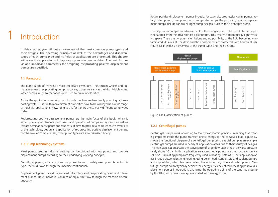
Rotary positive displacement pumps include, for example, progressive cavity pumps, ro-tary piston pumps, gear pumps or screw spindle pumps� Reciprocating positive displace-ment pumps include various plunger pump designs, such as the diaphragm pump�
The diaphragm pump is an advancement of the plunger pump� The fluid to be conveyed is separated from the drive side by a diaphragm� This creates a hermetically tight work-ing space� There are no external emissions and no possibility of the fluid becoming con-taminated� As a result, the drive and the environment are protected from harmful fluids� Figure 1�1 provides an overview of the pump types and their designs�
Positive displacement pumps Flow pumps
Centrifugal pumps
Axi
al fl
ow p
umps
Radi
al fl
ow p
umps
……
Hos
e di
aphr
agm
pum
ps
Air
oper
ated
dia
phra
gmpu
mps
Plun
ger
and
diap
hrag
m
pum
ps
…
Gea
r pu
mps
Vane
pum
ps
Prog
ress
ive
cavi
ty p
umps
Rota
ry p
isto
n pu
mps
Reciprocating positive displacement pumps
Rotating positive displacement pumps
Figure 1�1: Classification of pumps
1.2.1 Centrifugal pumps
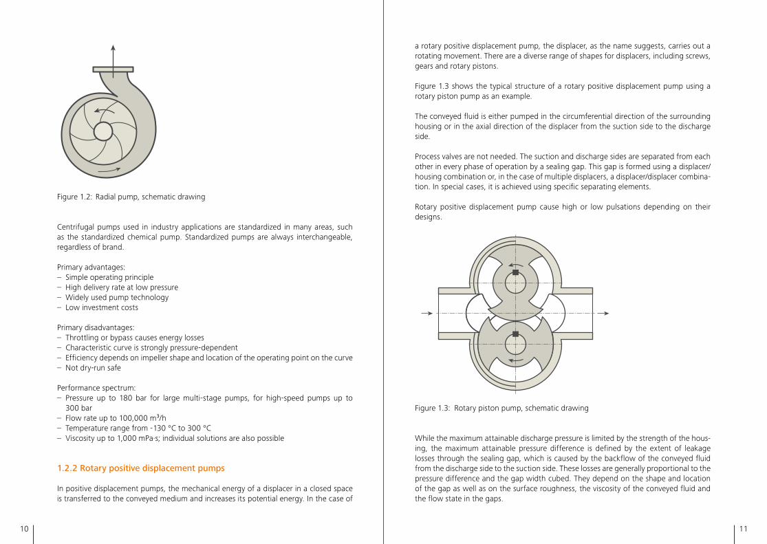
Centrifugal pumps work according to the hydrodynamic principle, meaning that rotat-ing impellers inside the pump transfer kinetic energy to the conveyed fluid� Figure 1�2 shows the functional diagram of a centrifugal pump using a radial pump as an example� Centrifugal pumps are used in nearly all application areas due to their variety of designs� The main application area is the conveyance of large flow rates at relatively low pressure, rarely above 10 bar� In this application area, centrifugal pumps are the most economical solution� Circulating pumps are frequently used in heating systems� Other application ar-eas include power plant engineering, using boiler feed, condensate and coolant pumps, and shipbuilding, which features coolant, fire extinguisher, bilge and ballast pumps� Cen-trifugal pumps do not typically achieve the energy efficiency of reciprocating positive dis-placement pumps in operation� Changing the operating points of the centrifugal pump by throttling or bypass is always associated with energy losses�
10 11
Figure 1�2: Radial pump, schematic drawing
Centrifugal pumps used in industry applications are standardized in many areas, such as the standardized chemical pump� Standardized pumps are always interchangeable, regardless of brand�
Primary advantages:– Simple operating principle– High delivery rate at low pressure – Widely used pump technology– Low investment costs
Primary disadvantages:– Throttling or bypass causes energy losses– Characteristic curve is strongly pressure-dependent– Efficiency depends on impeller shape and location of the operating point on the curve – Not dry-run safe
Performance spectrum:– Pressure up to 180 bar for large multi-stage pumps, for high-speed pumps up to
300 bar– Flow rate up to 100,000 m³/h– Temperature range from - 130 °C to 300 °C– Viscosity up to 1,000 mPa·s; individual solutions are also possible
1.2.2 Rotary positive displacement pumps
In positive displacement pumps, the mechanical energy of a displacer in a closed space is transferred to the conveyed medium and increases its potential energy� In the case of
a rotary positive displacement pump, the displacer, as the name suggests, carries out a rotating movement� There are a diverse range of shapes for displacers, including screws, gears and rotary pistons�
Figure 1�3 shows the typical structure of a rotary positive displacement pump using a rotary piston pump as an example�
The conveyed fluid is either pumped in the circumferential direction of the surrounding housing or in the axial direction of the displacer from the suction side to the discharge side�
Process valves are not needed� The suction and discharge sides are separated from each other in every phase of operation by a sealing gap� This gap is formed using a displacer/housing combination or, in the case of multiple displacers, a displacer/displacer combina-tion� In special cases, it is achieved using specific separating elements�
Rotary positive displacement pump cause high or low pulsations depending on their designs�
Figure 1�3: Rotary piston pump, schematic drawing
While the maximum attainable discharge pressure is limited by the strength of the hous-ing, the maximum attainable pressure difference is defined by the extent of leakage losses through the sealing gap, which is caused by the backflow of the conveyed fluid from the discharge side to the suction side� These losses are generally proportional to the pressure difference and the gap width cubed� They depend on the shape and location of the gap as well as on the surface roughness, the viscosity of the conveyed fluid and the flow state in the gaps�
12 13
Applications for rotary positive displacement pumps range from conveying self-lubri-cating fluids, such as lubricating oil and hydraulic oil, to conveying viscous fluids, such as adhesives, pastes and fluids with solid admixtures� However, most designs are very sensitive to abrasive admixtures due to the low clearances between rotating and fixed components� Furthermore, a relatively large amount of fluid is exposed to shear stresses, i�e� the conveyance is less gentle and therefore only suitable to a limited extent for food products and sensitive organic substances� Unlike reciprocating positive displacement pumps, rotary pumps have no oscillating masses and no valves� As a result, it is pos-sible to achieve greater speeds and smaller, space-saving designs with direct coupling to electric motors�
Examples of rotary positive displacement pumps and their application areas:– Progressive cavity pump: construction industry, chemical industry, agriculture– Rotary piston pump: gentle conveyance, volatile and non-lubricating fluids, vacuums– Peristaltic pump: gentle conveyance, hygienic areas– Screw spindle pump: oil and gas industry, counters– Gear pump: self-lubricating high-viscosity fluids– Vane pump: high suction capacity, vacuums
Primary advantages:– Conveying direction usually reversible– Relatively steady flow rate– Self-priming– Dry-run safe under certain conditions– Low investment costs
Primary disadvantages:– Low clearances require very high production accuracy– Large internal leakages– Strong pulsating flow for some designs, e�g� up to more than 100% for the peristaltic
pump
Performance spectrum:– Pressure up to 300 bar– Flow rate from a few ml/h to approx� 340 m³/h– Temperature up to +450 °C– Viscosity up to approx� 400,000 mPa·s
1.2.3 Reciprocating positive displacement pumps
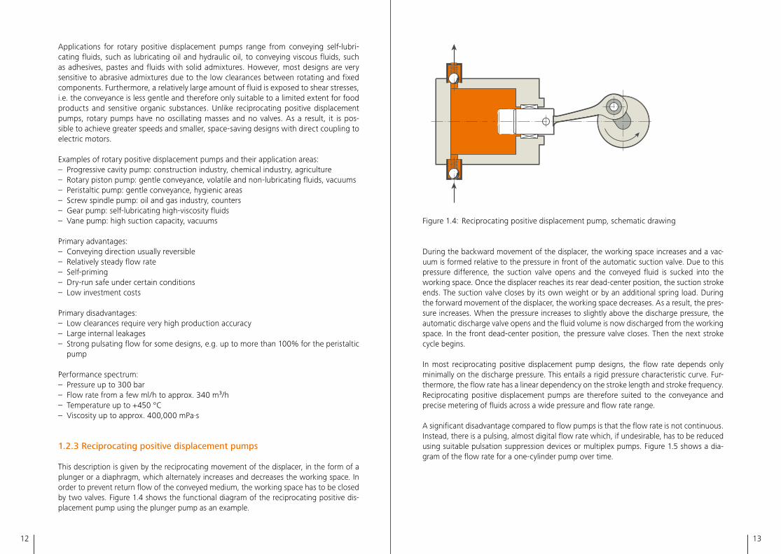
This description is given by the reciprocating movement of the displacer, in the form of a plunger or a diaphragm, which alternately increases and decreases the working space� In order to prevent return flow of the conveyed medium, the working space has to be closed by two valves� Figure 1�4 shows the functional diagram of the reciprocating positive dis-placement pump using the plunger pump as an example�
Figure 1�4: Reciprocating positive displacement pump, schematic drawing
During the backward movement of the displacer, the working space increases and a vac-uum is formed relative to the pressure in front of the automatic suction valve� Due to this pressure difference, the suction valve opens and the conveyed fluid is sucked into the working space� Once the displacer reaches its rear dead-center position, the suction stroke ends� The suction valve closes by its own weight or by an additional spring load� During the forward movement of the displacer, the working space decreases� As a result, the pres-sure increases� When the pressure increases to slightly above the discharge pressure, the automatic discharge valve opens and the fluid volume is now discharged from the working space� In the front dead-center position, the pressure valve closes� Then the next stroke cycle begins�
In most reciprocating positive displacement pump designs, the flow rate depends only minimally on the discharge pressure� This entails a rigid pressure characteristic curve� Fur-thermore, the flow rate has a linear dependency on the stroke length and stroke frequency� Reciprocating positive displacement pumps are therefore suited to the conveyance and precise metering of fluids across a wide pressure and flow rate range�
A significant disadvantage compared to flow pumps is that the flow rate is not continuous� Instead, there is a pulsing, almost digital flow rate which, if undesirable, has to be reduced using suitable pulsation suppression devices or multiplex pumps� Figure 1�5 shows a dia-gram of the flow rate for a one-cylinder pump over time�
14 15
Time
Stroke volume
Stroke volume
Stroke volume
Flow
rate
Figure 1�5: Pumping characteristic of a one-cylinder reciprocating positive displacement pump
Due to their design and limited speed, reciprocating positive displacement pumps do not reach the flow rates of other pump designs, such as centrifugal pumps�
Leak-free variants, i�e� hermetically tight diaphragm pumps, expand the application range of reciprocating positive displacement pumps enormously� As a result, it is possi-ble to convey both fluids with special properties, such as abrasive, explosive or corrosive fluids, as well as food products or medication under sterile conditions�
The application areas of the diaphragm pump range from manufacturing chemical inter-mediates and end products, to cracking and reforming processes in the petrochemical industry, to the food, pharmaceutical and biotechnology industries, to recipe mixing, hygienic processing as well as sterile metering�
The diaphragm can be driven pneumatically, mechanically or hydraulically� Diaphragm pumps with a hydraulically driven diaphragm are relatively elaborate and thus expensive due to their design� However, they offer a range of advantages in their application�
Primary advantages:– Extremely rigid pressure characteristic curve– Hermetically tight– Very precise metering– Dry-run safe– Self-priming under certain conditions
Primary disadvantages:– Flow rate limited to approx� 1,500 m³/h– Pulsating flow rate– High investment costs
Performance spectrum:– Pressure range from vacuum up to 1,200 bar (max� 3,500 bar)– Flow rate of 1 ml/h to 1,500 m³/h– Temperature range from - 270 °C to + 500 °C– Viscosity range from 0�1 to 100,000 mPa·s
Since displacement pumps convey a defined volume per stroke or revolution regardless of the differential pressure, they can be used for precise fluid metering, and are therefore also called metering pumps� In this book, the term "metering pump" is used for recipro-cating positive displacement pumps, although rotary positive displacement pumps are also a type of metering pumps�
In this book, the term "process pump" is also used for pumps with high hydraulic power� Depending on the application, process pumps may focus purely on conveying fluid, i�e� transferring it without metering� However, process pumps can also be used for precise metering�
1.2.4 Comparison of the different pump types
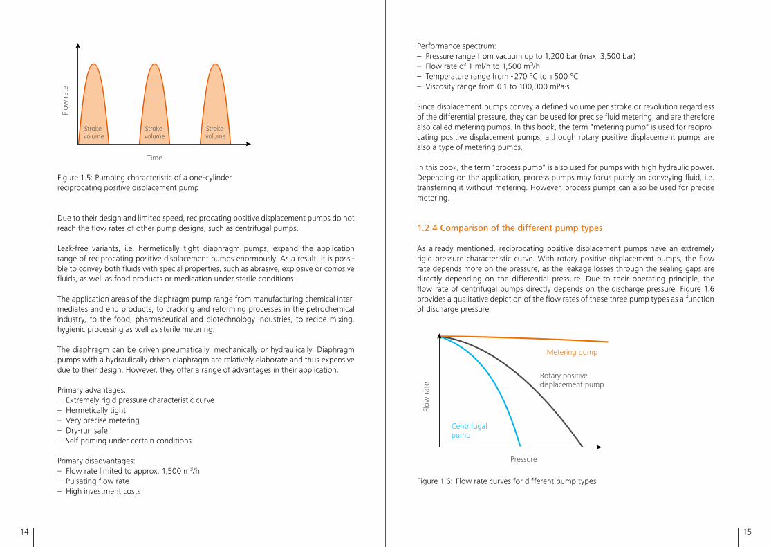
As already mentioned, reciprocating positive displacement pumps have an extremely rigid pressure characteristic curve� With rotary positive displacement pumps, the flow rate depends more on the pressure, as the leakage losses through the sealing gaps are directly depending on the differential pressure� Due to their operating principle, the flow rate of centrifugal pumps directly depends on the discharge pressure� Figure 1�6 provides a qualitative depiction of the flow rates of these three pump types as a function of discharge pressure�
Metering pump
Rotary positive displacement pump
Centrifugal pump
Pressure
Flow
rate
Figure 1�6: Flow rate curves for different pump types
16 17
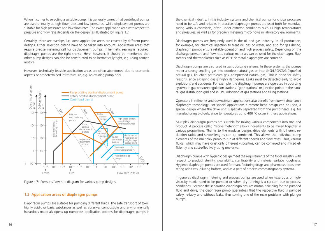
When it comes to selecting a suitable pump, it is generally correct that centrifugal pumps are used primarily at high flow rates and low pressures, while displacement pumps are suitable for high pressures and low flow rates� The exact application area with respect to pressure and flow rate depends on the design, as illustrated by Figure 1�7�
Certainly, there are overlaps, i�e� some application areas are covered by different pump designs� Other selection criteria have to be taken into account� Application areas that require precise metering call for displacement pumps� If hermetic sealing is required, diaphragm pumps are the right choice� Here, however, it should be mentioned that other pump designs can also be constructed to be hermetically tight, e�g� using canned motors�
However, technically feasible application areas are often abandoned due to economic aspects or predetermined infrastructure, e�g� an existing pump pool�
10-1
1
10
102
103
10
102
103
104
1
1W
1kW
1MW
1 ml/h 1 l/h
10-6 10-5 10-4 10-3 10-2 10-1 1 10 102 103 104 105
1MW
Ope
ratin
g pr
essu
re
in b
ar
Del
iver
y he
ight
in
m
Reciprocating positive displacement pumpRotary positive displacement pumpCentrifugal pumps
Process and metering pumps
Semi-axialcentrifugal pumps
Axial centrifugalpumps
Low pressure diaphragm pumps
Mic
ro m
eter
ing
/la
bora
tory
pum
ps
Radialcentrifugalpumps
Radial centri- fugal pumps(single-stage,double-inlet)
High speed pumps+ multi-stagecentrifugal pumps
Triplex prozess- pumps
Side channel pumps
Rotary positive
displacement pumps
Flow rate in m3/h
Figure 1�7: Pressure/flow rate diagram for various pump designs
1.3 Application areas of diaphragm pumps
Diaphragm pumps are suitable for pumping different fluids� The safe transport of toxic, highly acidic or basic substances as well as abrasive, combustible and environmentally hazardous materials opens up numerous application options for diaphragm pumps in
the chemical industry� In this industry, systems and chemical pumps for critical processes need to be safe and reliable� In practice, diaphragm pumps are used both for manufac-turing various chemicals, often under extreme conditions such as high temperatures and pressures, as well as for precisely metering micro flows in laboratory environments�
Diaphragm pumps are frequently used in the oil and gas industry� In oil production, for example, for chemical injection to treat oil, gas or water, and also for gas drying, diaphragm pumps ensure reliable operation and high process safety� Depending on the discharge pressure and flow rate, various materials can be used for the diaphragm� Elas-tomers and thermoplastics such as PTFE or metal diaphragms are common�
Diaphragm pumps are also used in gas odorizing systems� In these systems, the pumps meter a strong-smelling gas into odorless natural gas or into LNG/LPG/CNG (liquefied natural gas, liquefied petroleum gas, compressed natural gas)� This is done for safety reasons, since escaping gas is highly dangerous� Leaks must be detected early to avoid explosions and accidents� For example, the diaphragm pumps are operated in odorizing systems at gas pressure regulation stations, "gate stations" or junction points in the natu-ral gas distribution grid and in LPG odorizing at gas stations and filling stations�
Operators in refineries and downstream applications also benefit from low-maintenance diaphragm technology� For special applications a remote head design can be used, a special design where the drive unit is spatially separated from the pump head, e�g� for manufacturing biofuels, since temperatures up to 400 °C occur in these applications�
Multiplex diaphragm pumps are suitable for mixing various components into one end product� A process called "recipe metering" allows ingredients to be mixed together in various proportions� Thanks to the modular design, drive elements with different re-duction ratios and stroke lengths can be combined� This allows the individual pump elements of the multiplex pump to run at different speeds and flow rates� Thus, various fluids, which may have drastically different viscosities, can be conveyed and mixed ef-ficiently and cost-effectively using one drive�
Diaphragm pumps with hygienic design meet the requirements of the food industry with respect to product sterility, cleanability, sterilizability and material surface roughness� Hygienic diaphragm pumps are used for manufacturing drugs and pharmaceuticals, me-tering additives, diluting buffers, and as a part of process chromatography systems�
In general, diaphragm metering and process pumps are used when hazardous or high-viscosity media need to be pumped or when dry running is a concern due to process conditions� Because the separating diaphragm ensures mutual shielding for the pumped fluid and drive, the diaphragm pump guarantees that the respective fluid is pumped safely, reliably and without leaks, thus solving one of the main problems with plunger pumps�
18 19
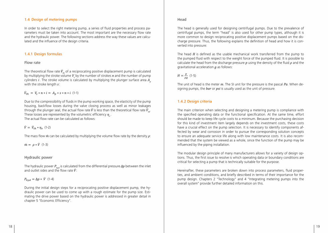
1.4 Design of metering pumps
In order to select the right metering pump, a series of fluid properties and process pa-rameters must be taken into account� The most important are the necessary flow rate and the hydraulic power� The following sections address the way these values are calcu-lated and the influence of the design criteria�
1.4.1 Design formulas
Flow rate
The theoretical flow rate th of a reciprocating positive displacement pump is calculated by multiplying the stroke volume Vs by the number of strokes n and the number of pump cylinders i � The stroke volume is calculated by multiplying the plunger surface area Ap with the stroke length s :
(1-1)
Due to the compressibility of fluids in the pump working space, the elasticity of the pump housing, backflow losses during the valve closing process as well as minor leakages through the plunger seal, the actual flow rate is less than the theoretical flow rate th� These losses are represented by the volumetric efficiency ηv � The actual flow rate can be calculated as follows:
(1-2)
The mass flow can be calculated by multiplying the volume flow rate by the density ρ:
(1-3)
Hydraulic power
The hydraulic power Phyd is calculated from the differential pressure Δp between the inlet and outlet sides and the flow rate :
(1-4)
During the initial design steps for a reciprocating positive displacement pump, the hy-draulic power can be used to come up with a rough estimate for the pump size� Esti-mating the drive power based on the hydraulic power is addressed in greater detail in chapter 5 "Economic Efficiency"�
Head
The head is generally used for designing centrifugal pumps� Due to the prevalence of centrifugal pumps, the term "head" is also used for other pump types, although it is more common to design reciprocating positive displacement pumps based on the dis-charge pressure� Thus, the following explains the definition of head and how it is con-verted into pressure:
The head H is defined as the usable mechanical work transferred from the pump to the pumped fluid with respect to the weight force of the pumped fluid� It is possible to calculate the head from the discharge pressure p using the density of the fluid ρ and the gravitational acceleration g as follows:
(1-5)
The unit of head is the meter m� The SI unit for the pressure is the pascal Pa� When de-signing pumps, the bar or psi is usually used as the unit of pressure�
1.4.2 Design criteria
The main criterion when selecting and designing a metering pump is compliance with the specified operating data or the functional specification� At the same time, effort should be made to keep life cycle costs to a minimum� Because the purchasing decision for this kind of investment item largely depends on the investment costs, these costs have a crucial effect on the pump selection� It is necessary to identify components af-fected by wear and corrosion in order to pursue the corresponding solution concepts to ensure an adequate service life along with low maintenance costs� It is also recom-mended that the system be viewed as a whole, since the function of the pump may be influenced by the piping installation�
The modular design principle of many manufacturers allows for a variety of design op-tions� Thus, the first issue to resolve is which operating data or boundary conditions are critical for selecting a pump that is technically suitable for the purpose�
Hereinafter, these parameters are broken down into process parameters, fluid proper-ties, and ambient conditions, and briefly described in terms of their importance for the pump design� Chapters 2 "Technology" and 4 "Integrating metering pumps into the overall system" provide further detailed information on this�
20 21
Process parameters
The model and the size of the pump are primarily determined by the process parameters, which include the pressures on the suction and discharge side, the flow rate and the fluid temperature� In addition, design pressures and design temperatures may place higher requirements on the pump�
It is generally necessary to be familiar with all process parameters; minimum and maxi-mum values, covering every possible operating state� For example, if a range is defined for the flow rate, not just a single operating point, then a stroke adjustment and/or a motor suited to the frequency inverter must be taken into account for reciprocating posi-tive displacement pumps�
Fluid properties
Fluid temperatures determine the design of the pump head� Depending on the dia-phragm material (PTFE, stainless steel, Hastelloy etc�), temperatures in a range of - 20 °C to 200 °C are permitted without any additional constructional measures� This tempera-ture range can be expanded using remote head solutions, as doing so decouples the process fluid from the drive unit� As a result, critical process conditions such as extreme temperatures or even radioactive radiation can be kept from affecting the displacement system, guaranteeing high system safety� Using this technology, temperatures up to 500 °C can be implemented�
If there is a major temperature difference between the fluid and the environment, a constant fluid temperature can be maintained in the pump heads using a heating or cooling jacket and/or insulation� High fluid temperatures result in increased heat transfer from the pump head to the drive unit� To ensure that this does not negatively impact the service life of the drive unit, cooling coils are built into the hydraulic oil reservoir�
The fluid temperature has a critical influence on the fluid properties themselves� Vis-cosity, density, vapor pressure and compressibility are dependent on temperature� The definition of a wide temperature range results in the corresponding ranges for the listed fluid parameters� The most unfavorable operating point has to be evaluated, considering the entire range of all fluid parameters�
The viscosity affects the selection of the valve and the stroke frequency� At high viscosi-ties, the closing delay of the valves must be taken into account in order to avoid a drop in flow rate� At the same time, to compensate for high viscosities, a moderate pump speed can be selected, which reduces the inlet pressure loss created by the inflow of the fluid flowing at the suction valve and inside the pump head� However, investment costs must also be considered� These costs can be reduced by selecting a smaller and more cost-effective pump that runs at a higher stroke frequency� At viscosities less than 1 mPa·s, occurring for instance with liquefied gases, there are suitable valve variants� This increases the service life of these wear parts�
The density is needed when a mass flow is being specified� The volume flow rate is al-ways used to design pumps and, as a result, it must be determined from the mass flow�
The vapor pressure has to be taken into account in the context of suction pressure as well as the pressure losses in the pump head and suction line� This is vital to avoid cavitation in the suction line and in the pump� For vapor pressures close to the suction pressure, it is necessary to optimize the inlet pressure loss through the selection of the valves and stroke frequency� Pump heads with heating/cooling jackets are used to cool the fluid in order to take advantage of the fact that the vapor pressure heavily depends on the tem-perature, e�g� for liquefied gases� For example, in CO₂ applications, cooling by 5K in the temperature range above 0 °C makes it possible to reduce the vapor pressure by 5 bar or more� As an alternative, booster pumps can be used if necessary�
The compressibility of a fluid determines the flow rate of the pump� If there is a large pressure increase, its influence is significant, again, especially in the case of liquefied gases� As the fluid temperature decreases, the compressibility decreases as well� Know-ing about this relationship allows for smaller pumps to be designed� At the same time, the fact that the heat of compression results in heating of the pump head must be taken into account in liquefied gas applications� A cooling device in the form of a heating/cool-ing jacket can be installed in these cases�
Other important fluid properties for selecting a pump include the fluid composition or concentration of its components, the solidification point and the solid content� Knowl-edge of the fluid composition is crucial for selecting suitable materials for wetted com-ponents, both in terms of corrosion as well as abrasion by hard materials� Regarding the resistance and service life, the assessment of the materials used must always take the fluid temperature into account�
The solidification point determines whether or not a heated pump head is required� Melts are not in the liquid phase at ambient temperature� Therefore, the head must be brought to the right temperature before the pump is started up so that the fluid is flowable�
Diaphragm pumps can be designed for metering suspensions and sludges� For this pur-pose, there are suitable suspension valves� Depending on the solids concentration, par-ticle size, particle density and the resulting settling rate, either moderate stroke frequen-cies are recommended to reduce suction pressure loss, or faster stroke frequencies are recommended to keep the suspended particles from settling in case of high settling rates� The hardness of the particles determines the material pairing for the valve parts�
Ambient conditions and installation sites
Ambient conditions such as temperature, direct sunlight, humidity, salty air in marine en-vironments, explosive environments, sand storms in desert areas and earthquake zones are also important for designing the pump� At high ambient temperatures and simul-taneously high drive loads, a cooling system for the drive unit may be necessary� Fur-
2322
thermore, all technical components, such as motors, electric actuators and instruments, must be designed for the maximum and minimum ambient temperatures. This can be supplemented by other constructive measures, such as sun shields and housings for low temperatures, to enable trouble-free use in regions with desert, tropical or continental climates.
Marine or other corrosive ambient conditions result in higher rates of surface corrosion. A suitable offshore painting system can therefore guarantee a long service life. Here, DIN EN ISO 12944 specifies C5-M as the highest corrosion protection class.
The explosion zone classification determines the technical design for all electrical and mechanical components. If the available supply voltage fluctuates, this must be taken into account when selecting the motor. A specified earthquake zone affects the design of the steel structures for the pump, like the base plate and the motor flange.
Process parameters, fluid properties and ambient conditions are all very important for designing the pump. These factors must be discussed in detail with the pump manufac-turer in order to ensure the function of the pump even at extreme operating and bound-ary conditions over a long period.
2 TechnologyIn this chapter you will learn the function of the most important components of reciprocating positive displacement pumps. A lot of manufacturers offer a modu-larized pump program with a range of components to suit many special require-ments. Therefore, the chapter is structured module oriented in drive and drive unit components, pump heads, fluid valves and diaphragms. Particular attention was paid to concepts customary in the market. For a better explanation of the current status, the basic features in the area of pump head technology are described as an evolutionary development process.
2.1 Modularity of reciprocating positive displacement pumps
Reciprocating positive displacement pumps can be used to convey a wide variety of liq-uids in various industries and processes within a broad spectrum of pressure and perfor-mance because of their many advantages. Reciprocating positive displacement pumps are usually provided in a modular system with interchangeable pump components. Thus, they can be used by pump operators in an economically reasonable way to cover such a broad range of applications with complex requirements.
2.1.1 Pump construction kit
Flexible solutions can be configured with a modular construction kit. These construction systems allow the use of specific, customized parts in certain places in order to meet the special, individual requirements of the customer. At the same time, they allow the use of cost-effective serial parts for the rest of the pump to reduce construction and cost efforts.
Depending on market demand, pump kits are more or less extensive. It can be observed that kits for small pumps are generally larger than those in high performance classes. The reason for this is the higher number of small pump units sold.
Despite the market of diaphragm metering pumps being comparatively small, it features a very wide variety of different technical solutions and products. Diaphragm metering pumps are used to convey flow rates from a few millimeters per hour all the way up to hundreds of cubic meters. Discharge pressures can range from a few millibar to well over a thousand bar. Without the highly sophisticated construction kits of reciprocating
2524
2.1.2 An overview of construction kit components
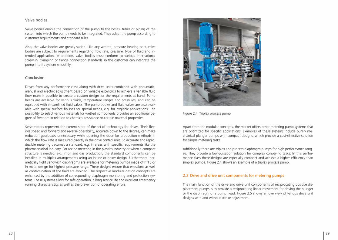
The main components of a reciprocating positive displacement pump kit, pictured in figure 2�3, include the following:
– Drive, e�g� electric motor– Drive unit, e�g� gear for increasing torque and housing a crank drive– Diaphragm pump head, e�g� with plunger and hydraulic part for driving the diaphragm– Fluid valves for controlling the flow– Valve body for adaptation to the specific customer piping
V•
Motor
Variable speed gear
Reduction gear
Pump head
Drive
Drive element
2.3
Figure 2�3: Pump components
The variability and economy of the kit are the result of both practical standardization and proper flexible design of relevant components� Optimal function, good efficiency and suitable material variants are the decisive factors here� The main components of a metering pump are structured as follows:
Drive
The pump drive converts primary power into secondary power�
This mostly involves converting electrical power into mechanical rotary motion� Typically this is done using standard electric 3-phase motors selected according to respective power requirements� To adjust the flow rate, 3-phase motors can provide variable speed when combined with electric frequency inverters�
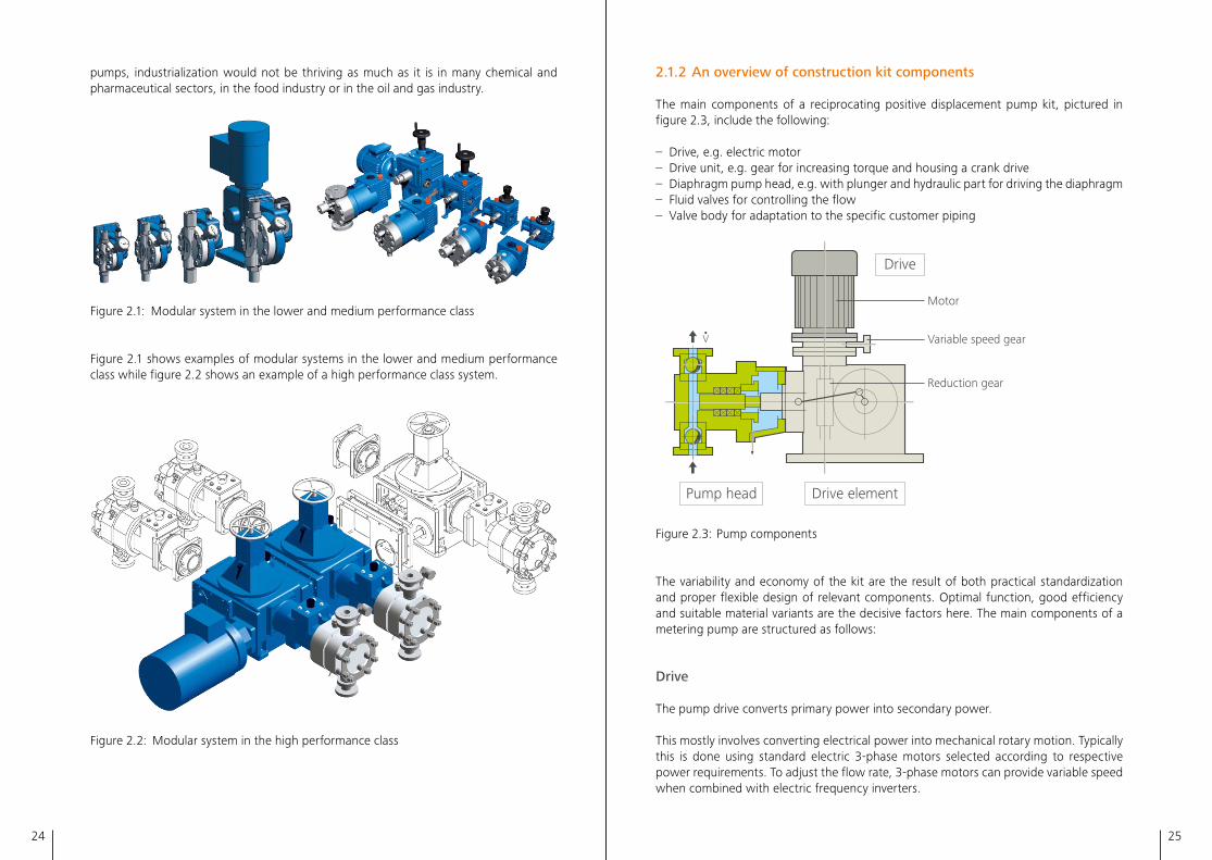
pumps, industrialization would not be thriving as much as it is in many chemical and pharmaceutical sectors, in the food industry or in the oil and gas industry�
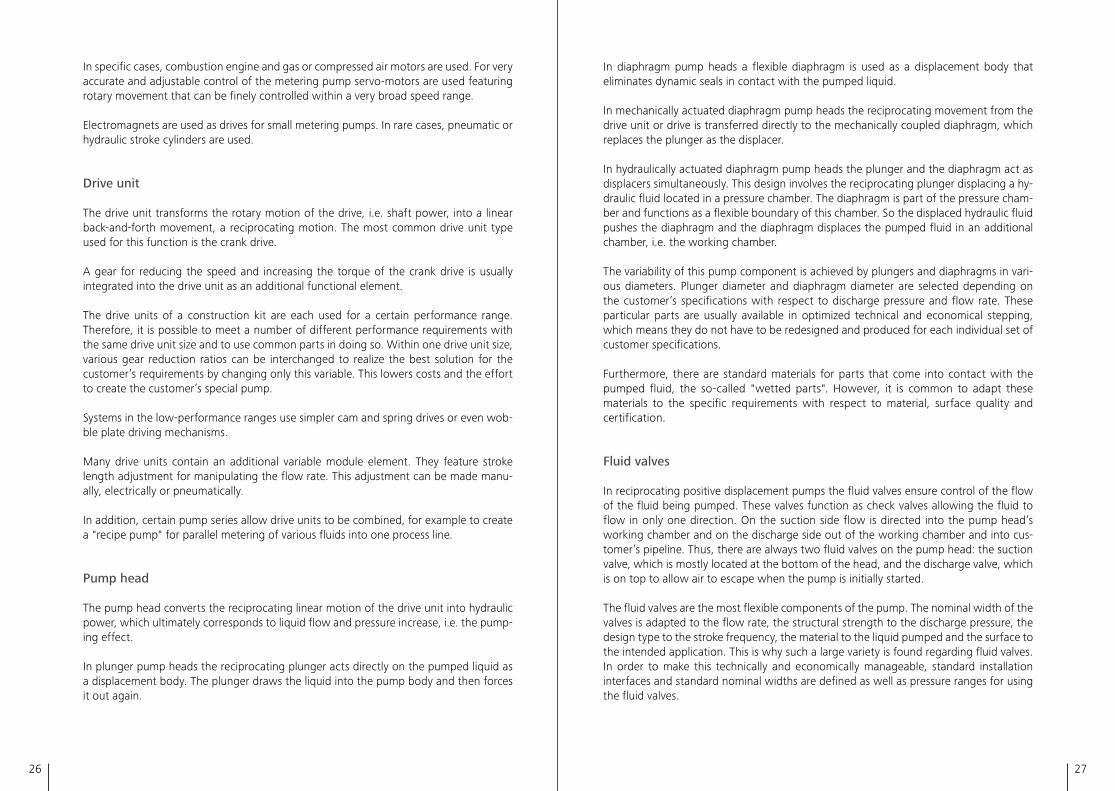
Figure 2�1: Modular system in the lower and medium performance class
Figure 2�1 shows examples of modular systems in the lower and medium performance class while figure 2�2 shows an example of a high performance class system�
Figure 2�2: Modular system in the high performance class
26 27
In diaphragm pump heads a flexible diaphragm is used as a displacement body that eliminates dynamic seals in contact with the pumped liquid�
In mechanically actuated diaphragm pump heads the reciprocating movement from the drive unit or drive is transferred directly to the mechanically coupled diaphragm, which replaces the plunger as the displacer�
In hydraulically actuated diaphragm pump heads the plunger and the diaphragm act as displacers simultaneously� This design involves the reciprocating plunger displacing a hy-draulic fluid located in a pressure chamber� The diaphragm is part of the pressure cham-ber and functions as a flexible boundary of this chamber� So the displaced hydraulic fluid pushes the diaphragm and the diaphragm displaces the pumped fluid in an additional chamber, i�e� the working chamber�
The variability of this pump component is achieved by plungers and diaphragms in vari-ous diameters� Plunger diameter and diaphragm diameter are selected depending on the customer’s specifications with respect to discharge pressure and flow rate� These particular parts are usually available in optimized technical and economical stepping, which means they do not have to be redesigned and produced for each individual set of customer specifications�
Furthermore, there are standard materials for parts that come into contact with the pumped fluid, the so-called "wetted parts"� However, it is common to adapt these materials to the specific requirements with respect to material, surface quality and certification�
Fluid valves
In reciprocating positive displacement pumps the fluid valves ensure control of the flow of the fluid being pumped� These valves function as check valves allowing the fluid to flow in only one direction� On the suction side flow is directed into the pump head’s working chamber and on the discharge side out of the working chamber and into cus-tomer’s pipeline� Thus, there are always two fluid valves on the pump head: the suction valve, which is mostly located at the bottom of the head, and the discharge valve, which is on top to allow air to escape when the pump is initially started�
The fluid valves are the most flexible components of the pump� The nominal width of the valves is adapted to the flow rate, the structural strength to the discharge pressure, the design type to the stroke frequency, the material to the liquid pumped and the surface to the intended application� This is why such a large variety is found regarding fluid valves� In order to make this technically and economically manageable, standard installation interfaces and standard nominal widths are defined as well as pressure ranges for using the fluid valves�
In specific cases, combustion engine and gas or compressed air motors are used� For very accurate and adjustable control of the metering pump servo-motors are used featuring rotary movement that can be finely controlled within a very broad speed range�
Electromagnets are used as drives for small metering pumps� In rare cases, pneumatic or hydraulic stroke cylinders are used�
Drive unit
The drive unit transforms the rotary motion of the drive, i�e� shaft power, into a linear back-and-forth movement, a reciprocating motion� The most common drive unit type used for this function is the crank drive�
A gear for reducing the speed and increasing the torque of the crank drive is usually integrated into the drive unit as an additional functional element�
The drive units of a construction kit are each used for a certain performance range� Therefore, it is possible to meet a number of different performance requirements with the same drive unit size and to use common parts in doing so� Within one drive unit size, various gear reduction ratios can be interchanged to realize the best solution for the customer’s requirements by changing only this variable� This lowers costs and the effort to create the customer’s special pump�
Systems in the low-performance ranges use simpler cam and spring drives or even wob-ble plate driving mechanisms�
Many drive units contain an additional variable module element� They feature stroke length adjustment for manipulating the flow rate� This adjustment can be made manu-ally, electrically or pneumatically�
In addition, certain pump series allow drive units to be combined, for example to create a "recipe pump" for parallel metering of various fluids into one process line�
Pump head
The pump head converts the reciprocating linear motion of the drive unit into hydraulic power, which ultimately corresponds to liquid flow and pressure increase, i�e� the pump-ing effect�
In plunger pump heads the reciprocating plunger acts directly on the pumped liquid as a displacement body� The plunger draws the liquid into the pump body and then forces it out again�
28 29
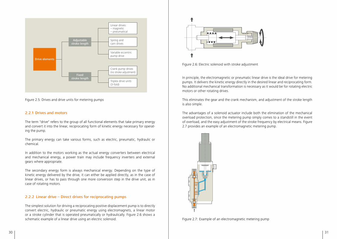
Figure 2�4: Triplex process pump
Apart from the modular concepts, the market offers other metering pump systems that are optimized for specific applications� Examples of these systems include purely me-chanical plunger pumps with compact designs, which provide a cost-effective solution for simple metering tasks�
Additionally there are triplex and process diaphragm pumps for high performance rang-es� They provide a low-pulsation solution for complex conveying tasks� In this perfor-mance class these designs are especially compact and achieve a higher efficiency than simplex pumps� Figure 2�4 shows an example of a triplex process pump�
2.2 Drive and drive unit components for metering pumps
The main function of the drive and drive unit components of reciprocating positive dis-placement pumps is to provide a reciprocating linear movement for driving the plunger or the diaphragm of a pump head� Figure 2�5 shows an overview of various drive unit designs with and without stroke adjustment�
Valve bodies
Valve bodies enable the connection of the pump to the hoses, tubes or piping of the system into which the pump needs to be integrated� They adapt the pump according to customer requirements and standard rules�
Also, the valve bodies are greatly varied� Like any wetted, pressure-bearing part, valve bodies are subject to requirements regarding flow rate, pressure, type of fluid and in-tended application� In addition, valve bodies must conform to various international screw-in, clamping or flange connection standards so the customer can integrate the pump into its system smoothly�
Conclusion
Drives from any performance class along with drive units combined with pneumatic, manual and electric adjustment based on variable eccentrics to achieve a variable fluid flow make it possible to create a custom design for the requirements at hand� Pump heads are available for various fluids, temperature ranges and pressures, and can be equipped with streamlined fluid valves� The pump bodies and fluid valves are also avail-able with special surface finishes for special needs, e�g� for hygienic applications� The possibility to select various materials for wetted components provides an additional de-gree of freedom in relation to chemical resistance or certain material properties�
Servomotors represent the current state of the art of technology for drives� Their flex-ible speed and forward and reverse operability, accurate down to the degree, can make reduction gearboxes unnecessary while opening the door for production methods in which the flow rate is measured directly in the drive control unit� So accurate and repro-ducible metering becomes a standard, e�g� in areas with specific requirements like the pharmaceutical industry� For recipe metering in the plastics industry or when a compact structure is needed, e�g� in oil and gas production, the standard components can be installed in multiplex arrangements using an in-line or boxer design� Furthermore, her-metically tight sandwich diaphragms are available for metering pumps made of PTFE or in metal design for highest pressure range� These designs ensure that emissions as well as contamination of the fluid are avoided� The respective modular design concepts are enhanced by the addition of corresponding diaphragm monitoring and protection sys-tems� These systems allow for safe operation, a long service life and excellent emergency running characteristics as well as the prevention of operating errors�
30 31
2.6
Figure 2�6: Electric solenoid with stroke adjustment
In principle, the electromagnetic or pneumatic linear drive is the ideal drive for metering pumps� It delivers the kinetic energy directly in the desired linear and reciprocating form� No additional mechanical transformation is necessary as it would be for rotating electric motors or other rotating drives�
This eliminates the gear and the crank mechanism, and adjustment of the stroke length is also simple�
The advantages of a solenoid actuator include both the elimination of the mechanical overload protection, since the metering pump simply comes to a standstill in the event of overload, and the easy adjustment of the stroke frequency by electrical means� Figure 2�7 provides an example of an electromagnetic metering pump�
2.8
Figure 2�7: Example of an electromagnetic metering pump
Drive elements
Adjustablestroke length
Linear drives: – magnetic – pneumatical
Spring and cam drives
Variable eccentric pump drive
Crank pump drives (no stroke adjustment)
Triplex drive units (3-fold)
Fixedstroke length
2.5
Figure 2�5: Drives and drive units for metering pumps
2.2.1 Drives and motors
The term "drive" refers to the group of all functional elements that take primary energy and convert it into the linear, reciprocating form of kinetic energy necessary for operat-ing the pump�
The primary energy can take various forms, such as electric, pneumatic, hydraulic or chemical�
In addition to the motors working as the actual energy converters between electrical and mechanical energy, a power train may include frequency inverters and external gears where appropriate�
The secondary energy form is always mechanical energy� Depending on the type of kinetic energy delivered by the drive, it can either be applied directly, as in the case of linear drives, or has to pass through one more conversion step in the drive unit, as in case of rotating motors�
2.2.2 Linear drive – Direct drives for reciprocating pumps
The simplest solution for driving a reciprocating positive displacement pump is to directly convert electric, hydraulic or pneumatic energy using electromagnets, a linear motor or a stroke cylinder that is operated pneumatically or hydraulically� Figure 2�6 shows a schematic example of a linear drive using an electric solenoid�
32 33
Primary disadvantages:– Impact motion sequence– Relatively low axial forces– Only suitable for small flow rates and pressures– Higher sound level for pneumatic drive– Poor efficiency for pneumatic drive– High complexity for hydraulic drive
Areas of application:– Gas odorization (also refer to chapter 6�2 "Odorization – Gas odorization in the natural
gas distribution grid"), chemical process engineering– Micro flow metering (also refer to chapter 6�12 "Drive technology – Continuous meter-
ing of micro flows")– Laboratories and pilot plants
2.2.3 Rotating pump drives
All motor principles that convert the deployed primary energy into rotating kinetic en-ergy, which is subsequently transformed into oscillating kinetic energy by drive units, constitute rotating pump drives� The most important principles will be presented below�
2.2.3.1 Electromotive drives
Electric motors are a standardized, cost-effective, long-lasting and tried-and-tested type of pump drive� That is why they are used in the majority of pump applications of all kinds�
International standardization relates to both the electrical aspects, with regard to power supply and frequency, as well as the mechanical aspects of the motor, in reference to mounting flange and drive shaft geometry�
One substantial selection criteria for the type of electric motor drive is determined by the electric energy supply available at the installation site� Power is most commonly sup-plied using a three-phase AC mains at different voltages and frequencies, providing the advantage of the rotating field that exists in this type of network�
For pump applications, it is most common to use asynchronous and synchronous ma-chines, which are available for the different global voltage levels� Local power networks available to the consumer lie in the low-voltage range between 110 volts and 690 volts� Industrial networks in the medium-voltage range lie between 6,000 volts and 30,000 volts� The power frequencies vary to a lesser extent and are at 50 Hz or 60 Hz�
Energy is harvested by photovoltaic modules generating their own DC power networks for dosing and pumping applications miles from anywhere that lack connections to elec-
As a matter of principle, pneumatic drives offer better explosion protection than electric solutions�
Hydraulic drives allow large forces and make it relatively easy to control the stroke fre-quency� However, they require a relatively large effort in terms of providing the neces-sary hydraulic energy and control�
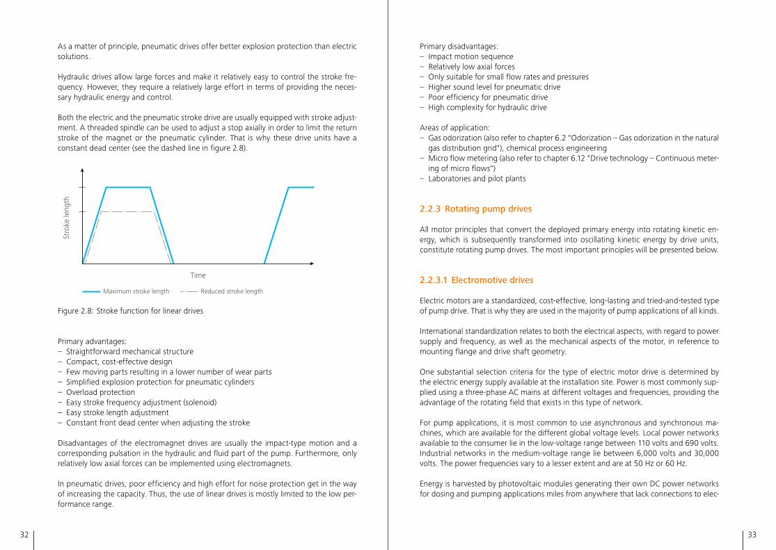
Both the electric and the pneumatic stroke drive are usually equipped with stroke adjust-ment� A threaded spindle can be used to adjust a stop axially in order to limit the return stroke of the magnet or the pneumatic cylinder� That is why these drive units have a constant dead center (see the dashed line in figure 2�8)�
Time
Stro
ke le
ngth
Maximum stroke length Reduced stroke length
2.8
Figure 2�8: Stroke function for linear drives
Primary advantages:– Straightforward mechanical structure– Compact, cost-effective design– Few moving parts resulting in a lower number of wear parts– Simplified explosion protection for pneumatic cylinders– Overload protection– Easy stroke frequency adjustment (solenoid)– Easy stroke length adjustment– Constant front dead center when adjusting the stroke
Disadvantages of the electromagnet drives are usually the impact-type motion and a corresponding pulsation in the hydraulic and fluid part of the pump� Furthermore, only relatively low axial forces can be implemented using electromagnets�
In pneumatic drives, poor efficiency and high effort for noise protection get in the way of increasing the capacity� Thus, the use of linear drives is mostly limited to the low per-formance range�
34 35
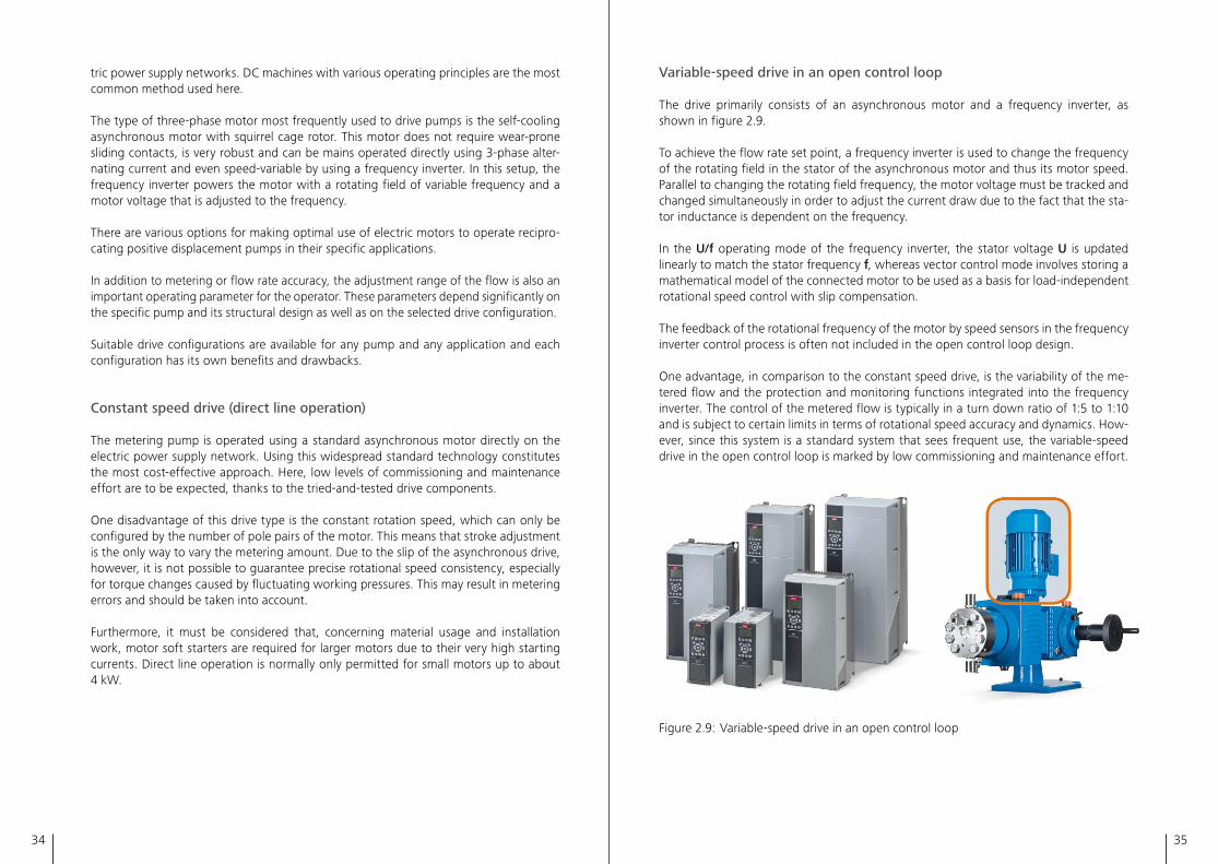
Variable-speed drive in an open control loop
The drive primarily consists of an asynchronous motor and a frequency inverter, as shown in figure 2�9�
To achieve the flow rate set point, a frequency inverter is used to change the frequency of the rotating field in the stator of the asynchronous motor and thus its motor speed� Parallel to changing the rotating field frequency, the motor voltage must be tracked and changed simultaneously in order to adjust the current draw due to the fact that the sta-tor inductance is dependent on the frequency�
In the U/f operating mode of the frequency inverter, the stator voltage U is updated linearly to match the stator frequency f, whereas vector control mode involves storing a mathematical model of the connected motor to be used as a basis for load-independent rotational speed control with slip compensation�
The feedback of the rotational frequency of the motor by speed sensors in the frequency inverter control process is often not included in the open control loop design�
One advantage, in comparison to the constant speed drive, is the variability of the me-tered flow and the protection and monitoring functions integrated into the frequency inverter� The control of the metered flow is typically in a turn down ratio of 1:5 to 1:10 and is subject to certain limits in terms of rotational speed accuracy and dynamics� How-ever, since this system is a standard system that sees frequent use, the variable-speed drive in the open control loop is marked by low commissioning and maintenance effort�
Figure 2�9: Variable-speed drive in an open control loop
(Left picture is used with permission of Danfoss GmbH)
tric power supply networks� DC machines with various operating principles are the most common method used here�
The type of three-phase motor most frequently used to drive pumps is the self-cooling asynchronous motor with squirrel cage rotor� This motor does not require wear-prone sliding contacts, is very robust and can be mains operated directly using 3-phase alter-nating current and even speed-variable by using a frequency inverter� In this setup, the frequency inverter powers the motor with a rotating field of variable frequency and a motor voltage that is adjusted to the frequency�
There are various options for making optimal use of electric motors to operate recipro-cating positive displacement pumps in their specific applications�
In addition to metering or flow rate accuracy, the adjustment range of the flow is also an important operating parameter for the operator� These parameters depend significantly on the specific pump and its structural design as well as on the selected drive configuration�
Suitable drive configurations are available for any pump and any application and each configuration has its own benefits and drawbacks�
Constant speed drive (direct line operation)
The metering pump is operated using a standard asynchronous motor directly on the electric power supply network� Using this widespread standard technology constitutes the most cost-effective approach� Here, low levels of commissioning and maintenance effort are to be expected, thanks to the tried-and-tested drive components�
One disadvantage of this drive type is the constant rotation speed, which can only be configured by the number of pole pairs of the motor� This means that stroke adjustment is the only way to vary the metering amount� Due to the slip of the asynchronous drive, however, it is not possible to guarantee precise rotational speed consistency, especially for torque changes caused by fluctuating working pressures� This may result in metering errors and should be taken into account�
Furthermore, it must be considered that, concerning material usage and installation work, motor soft starters are required for larger motors due to their very high starting currents� Direct line operation is normally only permitted for small motors up to about 4 kW�
36 37
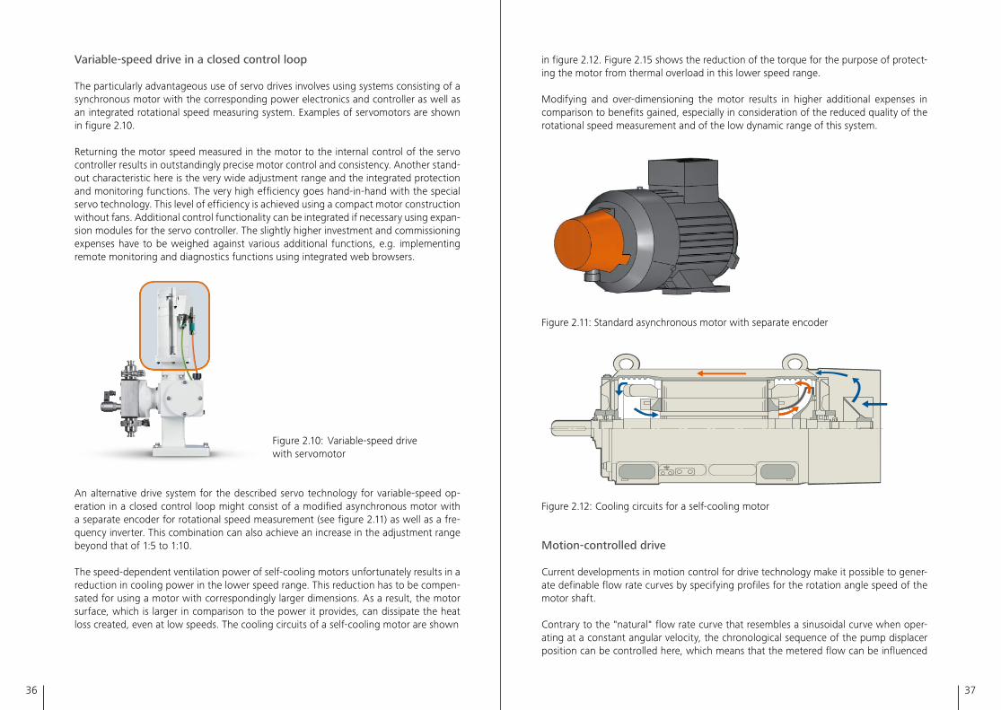
in figure 2�12� Figure 2�15 shows the reduction of the torque for the purpose of protect-ing the motor from thermal overload in this lower speed range�
Modifying and over-dimensioning the motor results in higher additional expenses in comparison to benefits gained, especially in consideration of the reduced quality of the rotational speed measurement and of the low dynamic range of this system�
Figure 2�11: Standard asynchronous motor with separate encoder
2.13
Figure 2�12: Cooling circuits for a self-cooling motor
Motion-controlled drive
Current developments in motion control for drive technology make it possible to gener-ate definable flow rate curves by specifying profiles for the rotation angle speed of the motor shaft�
Contrary to the "natural" flow rate curve that resembles a sinusoidal curve when oper-ating at a constant angular velocity, the chronological sequence of the pump displacer position can be controlled here, which means that the metered flow can be influenced
Variable-speed drive in a closed control loop
The particularly advantageous use of servo drives involves using systems consisting of a synchronous motor with the corresponding power electronics and controller as well as an integrated rotational speed measuring system� Examples of servomotors are shown in figure 2�10�
Returning the motor speed measured in the motor to the internal control of the servo controller results in outstandingly precise motor control and consistency� Another stand-out characteristic here is the very wide adjustment range and the integrated protection and monitoring functions� The very high efficiency goes hand-in-hand with the special servo technology� This level of efficiency is achieved using a compact motor construction without fans� Additional control functionality can be integrated if necessary using expan-sion modules for the servo controller� The slightly higher investment and commissioning expenses have to be weighed against various additional functions, e�g� implementing remote monitoring and diagnostics functions using integrated web browsers�
Figure 2�10: Variable-speed drive with servomotor
An alternative drive system for the described servo technology for variable-speed op-eration in a closed control loop might consist of a modified asynchronous motor with a separate encoder for rotational speed measurement (see figure 2�11) as well as a fre-quency inverter� This combination can also achieve an increase in the adjustment range beyond that of 1:5 to 1:10�
The speed-dependent ventilation power of self-cooling motors unfortunately results in a reduction in cooling power in the lower speed range� This reduction has to be compen-sated for using a motor with correspondingly larger dimensions� As a result, the motor surface, which is larger in comparison to the power it provides, can dissipate the heat loss created, even at low speeds� The cooling circuits of a self-cooling motor are shown
38 39
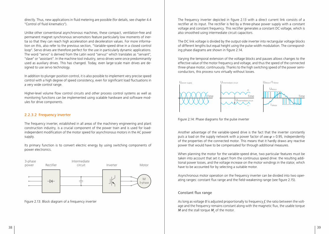
The frequency inverter depicted in figure 2�13 with a direct current link consists of a rectifier at its input� The rectifier is fed by a three-phase power supply with a constant voltage and constant frequency� This rectifier generates a constant DC voltage, which is also smoothed using intermediate circuit capacitors�
The DC link voltage is divided by the output-side inverter into rectangular voltage blocks of different lengths but equal height using the pulse width modulation� The correspond-ing phase diagrams are shown in figure 2�14�
Varying the temporal extension of the voltage blocks and pauses allows changes to the effective value of the motor frequency and voltage, and thus the speed of the connected three-phase motor, continuously� Thanks to the high switching speed of the power semi-conductors, this process runs virtually without losses�
Time
Upower supply
Time
Uintermediate circuit UMotor / I Motor
I Motor
UMotor+
Uintermediate circuit
–
Time
2.14
Figure 2�14: Phase diagrams for the pulse inverter
Another advantage of the variable-speed drive is the fact that the inverter constantly puts a load on the supply network with a power factor of cos φ > 0�95, independently of the properties of the connected motor� This means that it hardly draws any reactive power that would have to be compensated for through additional measures�
When planning the motor for the variable-speed drive, two particular features must be taken into account that set it apart from the continuous speed drive: the resulting addi-tional power losses, and the voltage increase on the motor windings in the stator, which have to be accounted for by selecting a suitable motor�
Asynchronous motor operation on the frequency inverter can be divided into two oper-ating ranges: constant flux range and the field-weakening range (see figure 2�15)�
Constant flux range
As long as voltage U is adjusted proportionally to frequency f, the ratio between the volt-age and the frequency remains constant along with the magnetic flux, the usable torque M and the stall torque Ms of the motor�
directly� Thus, new applications in fluid metering are possible (for details, see chapter 4�4 "Control of fluid kinematics")�
Unlike other conventional asynchronous machines, these compact, ventilation-free and permanent magnet synchronous servomotors feature particularly low moments of iner-tia so that they can reach high acceleration and deceleration values� For more informa-tion on this, also refer to the previous section, "Variable-speed drive in a closed control loop"� Servo drives are therefore perfect for the use in particularly dynamic applications� The word "servo" is derived from the Latin word "servus" which translates as "servant", "slave" or "assistant"� In the machine tool industry, servo drives were once predominantly used as auxiliary drives� This has changed� Today, even large-scale main drives are de-signed to use servo technology�
In addition to plunger position control, it is also possible to implement very precise speed control with a high degree of speed consistency, even for significant load fluctuations in a very wide control range�
Higher-level volume flow control circuits and other process control systems as well as monitoring functions can be implemented using scalable hardware and software mod-ules for drive components�
2.2.3.2 Frequency inverter
The frequency inverter, established in all areas of the machinery engineering and plant construction industry, is a crucial component of the power train and is used for load-independent modification of the motor speed for asynchronous motors in the AC power supply�
Its primary function is to convert electric energy by using switching components of power electronics�
3-phase power Rectifier
Intermediate circuit Inverter Motor
M3-phase
2.13
Figure 2�13: Block diagram of a frequency inverter
40 41
the resulting motor current� Despite this, however, the non-sinusoidal current curve re-sults in harmonics� The harmonics themselves lead to additional heat losses in the motor, which means they must also be considered when selecting a motor�
While an increase in the adjustable pulse frequency would reduce these losses in the motor, doing so would result in additional switching losses in the power semiconductor of the inverter�
Additional thermal loads in the inverter result from the motor cables�
Due to the geometric arrangement of the individual conductors and the materials used, they have a cable capacitance that increases in proportion to the cable length� Thus, longer motor cables mean non-negligible capacitance levels, especially when shielded motor cables are being used for EMC (Electromagnetic Compatibility) reasons, and mul-tiple motor cables must be laid in parallel for larger drive outputs�
These cable capacitances are reloaded through each switching action of the inverter's power semiconductor� As a result, additional current peaks are superimposed over the actual motor current�
Voltage stress of the motor windings
The fast switching processes of the power semiconductor causes high voltage rate-of-rise at the inverter output with a steepness of dU/dt and with typical values of 3 kV/ μs to 6 kV/ μs, running along the motor cable toward the motor at a speed of approx� 150 m/ μs (≈ half the speed of light)�
Because the motor has a considerably higher wave impedance than the motor cable, the voltage spike that reaches the motor coil is reflected and short-term peaks occur in the motor coil� These peaks can take on values up to twice as much as the DC link voltage�
The resulting voltage increases that occur even on relatively short line lengths are re-duced significantly when using motor reactors, dU/dt filters or sine-wave filters�
The drive system should be adjusted accordingly, also taking into account the lengths of the motor cables and, where appropriate, the use of suitable filters and the selection of the appropriate pulse frequency�
2.2.3.3 Other motor drives
In rare cases, especially if no electricity supply is available, other motor types are used to drive pumps�
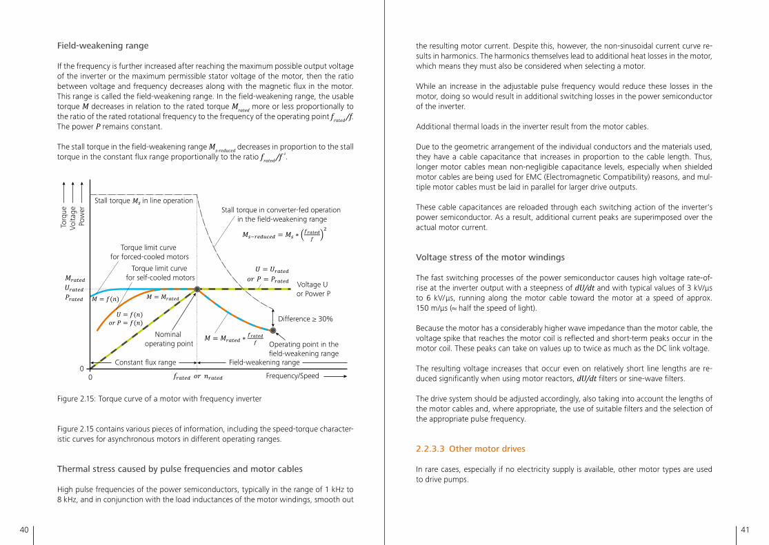
Field-weakening range
If the frequency is further increased after reaching the maximum possible output voltage of the inverter or the maximum permissible stator voltage of the motor, then the ratio between voltage and frequency decreases along with the magnetic flux in the motor� This range is called the field-weakening range� In the field-weakening range, the usable torque M decreases in relation to the rated torque Mrated more or less proportionally to the ratio of the rated rotational frequency to the frequency of the operating point frated /f� The power P remains constant�
The stall torque in the field-weakening range Ms-reduced decreases in proportion to the stall torque in the constant flux range proportionally to the ratio frated /f ²�
Volta
geTo
rque
Pow
er
Stall torque in line operationStall torque in converter-fed operation
in the field-weakening range
Torque limit curve for self-cooled motors
Torque limit curve for forced-cooled motors
Nominal operating point
Constant flux range
00
Field-weakening range
Operating point in the field-weakening range
Voltage U or Power P
Difference ≥ 30%
Frequency/Speed
2.15
Figure 2�15: Torque curve of a motor with frequency inverter
Figure 2�15 contains various pieces of information, including the speed-torque character-istic curves for asynchronous motors in different operating ranges�
Thermal stress caused by pulse frequencies and motor cables
High pulse frequencies of the power semiconductors, typically in the range of 1 kHz to 8 kHz, and in conjunction with the load inductances of the motor windings, smooth out
42 43
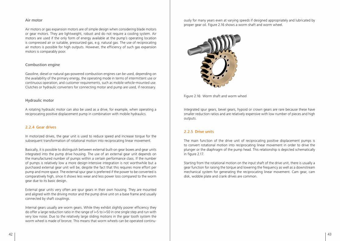
ously for many years even at varying speeds if designed appropriately and lubricated by proper gear oil� Figure 2�16 shows a worm shaft and worm wheel� 2.16
Figure 2�16: Worm shaft and worm wheel
Integrated spur gears, bevel gears, hypoid or crown gears are rare because these have smaller reduction ratios and are relatively expensive with low number of pieces and high outputs�
2.2.5 Drive units
The main function of the drive unit of reciprocating positive displacement pumps is to convert rotational motion into reciprocating linear movement in order to drive the plunger or the diaphragm of the pump head� This relationship is depicted schematically in figure 2�17�
Starting from the rotational motion on the input shaft of the drive unit, there is usually a gear function for raising the torque and lowering the frequency as well as a downstream mechanical system for generating the reciprocating linear movement� Cam gear, cam disk, wobble plate and crank drives are common�
Air motor
Air motors or gas expansion motors are of simple design when considering blade motors or gear motors� They are lightweight, robust and do not require a cooling system� Air motors are used if the only form of energy available at the pump’s operating location is compressed air or suitable, pressurized gas, e�g� natural gas� The use of reciprocating air motors is possible for high outputs� However, the efficiency of such gas expansion motors is comparably poor�
Combustion engine
Gasoline, diesel or natural gas-powered combustion engines can be used, depending on the availability of the primary energy, the operating mode in terms of intermittent use or continuous operation, and customer requirements, such as mobile vehicle-mounted use� Clutches or hydraulic converters for connecting motor and pump are used, if necessary�
Hydraulic motor
A rotating hydraulic motor can also be used as a drive, for example, when operating a reciprocating positive displacement pump in combination with mobile hydraulics�
2.2.4 Gear drives
In motorized drives, the gear unit is used to reduce speed and increase torque for the subsequent transformation of rotational motion into reciprocating linear movement�
Basically, it is possible to distinguish between external built-on gear boxes and gear units integrated into the pump drive housing� The use of an external gear unit depends on the manufactured number of pumps within a certain performance class� If the number of pumps is relatively low a more design-intensive integration is not worthwhile but a purchased external gear unit will be, despite the fact that this requires more effort per pump and more space� The external spur gear is preferred if the power to be converted is comparatively high, since it shows less wear and less power loss compared to the worm gear due to its basic design�
External gear units very often are spur gears in their own housing� They are mounted and aligned with the driving motor and the pump drive unit on a base frame and usually connected by shaft couplings�
Internal gears usually are worm gears� While they exhibit slightly poorer efficiency they do offer a large reduction ratio in the range of i=5 to i=50 in one single step and run with very low noise� Due to the relatively large sliding motions in the gear tooth system the worm wheel is made of bronze� This means that worm wheels can be operated continu-
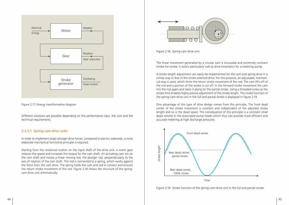
44 45
2.18
Figure 2�18: Spring-cam drive unit
The linear movement generated by a circular cam is sinusoidal and extremely constant stroke-for-stroke� It works particularly well as drive kinematics for a metering pump�
A stroke length adjustment can easily be implemented for the cam and spring drive in a similar way to that of the stroke solenoid drive� For this purpose, an adjustable, mechani-cal stop is used, which limits the return stroke movement of the rod� The cam lifts off of the rod and a portion of the stroke is cut off� In the forward stroke movement the cam hits the rod again and takes it along for the partial stroke� Using a threaded screw as the stroke limit enables highly precise adjustment of the stroke length� The stroke function of the spring-cam-drive unit in the full and partial stroke is displayed in figure 2�19�
One advantage of this type of drive design comes from this principle� The front dead center of the stroke movement is constant and independent of the adjusted stroke length and so is the dead space� The consequence of this principle is a constant small dead volume in the associated pump heads which thus can provide more efficient and accurate metering at high discharge pressures�
Stro
ke le
ngth
Front dead center
Rear dead center, partial stroke
Rear dead center, 100% stroke
Time
2.19
Figure 2�19: Stroke function of the spring-cam-drive unit in the full and partial stroke
Electrical
energyMotor
Rotation
Gear
Strokegenerator
Oscillating
linear motion
Gear reduction
Rotation
2.17
Figure 2�17: Energy transformation diagram
Different solutions are possible depending on the performance class, the cost and the technical requirements�
2.2.5.1 Spring-cam drive units
In order to implement larger plunger drive forces, compared to electric solenoids, a more elaborate mechanical functional principle is required�
Starting from the rotational motion on the input shaft of the drive unit, a worm gear reduces the speed and increases the torque for the cam shaft� An actuating cam sits on the cam shaft and moves a linear moving rod, the plunger rod, perpendicularly to the axis of rotation of the cam shaft� The rod is connected to a spring, which works against the force from the cam drive� The spring holds the cam and rod in contact and ensures the return stroke movement of the rod� Figure 2�18 shows the structure of the spring-cam drive unit schematically�
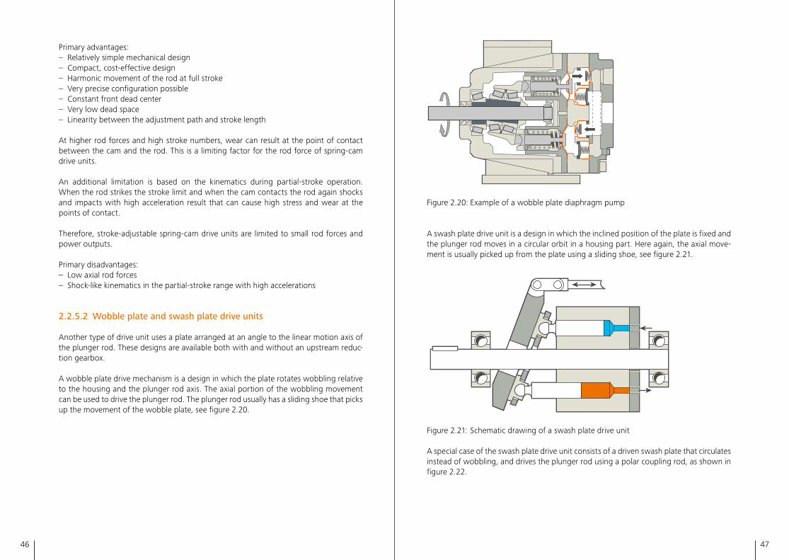
46 47
2.20
Figure 2�20: Example of a wobble plate diaphragm pump
A swash plate drive unit is a design in which the inclined position of the plate is fixed and the plunger rod moves in a circular orbit in a housing part� Here again, the axial move-ment is usually picked up from the plate using a sliding shoe, see figure 2�21�
2.21
Figure 2�21: Schematic drawing of a swash plate drive unit
A special case of the swash plate drive unit consists of a driven swash plate that circulates instead of wobbling, and drives the plunger rod using a polar coupling rod, as shown in figure 2�22�
Primary advantages:– Relatively simple mechanical design– Compact, cost-effective design– Harmonic movement of the rod at full stroke– Very precise configuration possible– Constant front dead center– Very low dead space– Linearity between the adjustment path and stroke length
At higher rod forces and high stroke numbers, wear can result at the point of contact between the cam and the rod� This is a limiting factor for the rod force of spring-cam drive units�
An additional limitation is based on the kinematics during partial-stroke operation� When the rod strikes the stroke limit and when the cam contacts the rod again shocks and impacts with high acceleration result that can cause high stress and wear at the points of contact�
Therefore, stroke-adjustable spring-cam drive units are limited to small rod forces and power outputs�
Primary disadvantages:– Low axial rod forces– Shock-like kinematics in the partial-stroke range with high accelerations
2.2.5.2 Wobble plate and swash plate drive units
Another type of drive unit uses a plate arranged at an angle to the linear motion axis of the plunger rod� These designs are available both with and without an upstream reduc-tion gearbox�
A wobble plate drive mechanism is a design in which the plate rotates wobbling relative to the housing and the plunger rod axis� The axial portion of the wobbling movement can be used to drive the plunger rod� The plunger rod usually has a sliding shoe that picks up the movement of the wobble plate, see figure 2�20�
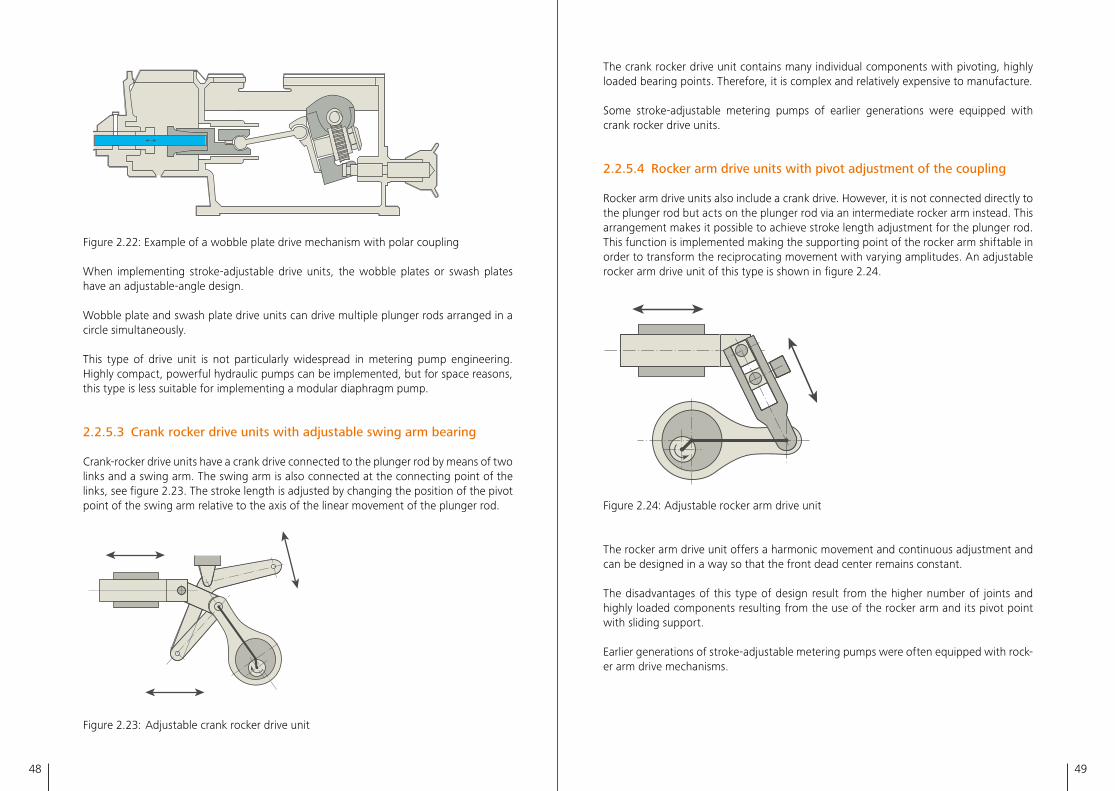
48 49
The crank rocker drive unit contains many individual components with pivoting, highly loaded bearing points� Therefore, it is complex and relatively expensive to manufacture� Some stroke-adjustable metering pumps of earlier generations were equipped with crank rocker drive units�
2.2.5.4 Rocker arm drive units with pivot adjustment of the coupling
Rocker arm drive units also include a crank drive� However, it is not connected directly to the plunger rod but acts on the plunger rod via an intermediate rocker arm instead� This arrangement makes it possible to achieve stroke length adjustment for the plunger rod� This function is implemented making the supporting point of the rocker arm shiftable in order to transform the reciprocating movement with varying amplitudes� An adjustable rocker arm drive unit of this type is shown in figure 2�24�
2.24
Figure 2�24: Adjustable rocker arm drive unit
The rocker arm drive unit offers a harmonic movement and continuous adjustment and can be designed in a way so that the front dead center remains constant�
The disadvantages of this type of design result from the higher number of joints and highly loaded components resulting from the use of the rocker arm and its pivot point with sliding support�
Earlier generations of stroke-adjustable metering pumps were often equipped with rock-er arm drive mechanisms�
2.23
Figure 2�22: Example of a wobble plate drive mechanism with polar coupling
When implementing stroke-adjustable drive units, the wobble plates or swash plates have an adjustable-angle design�
Wobble plate and swash plate drive units can drive multiple plunger rods arranged in a circle simultaneously�
This type of drive unit is not particularly widespread in metering pump engineering� Highly compact, powerful hydraulic pumps can be implemented, but for space reasons, this type is less suitable for implementing a modular diaphragm pump�
2.2.5.3 Crank rocker drive units with adjustable swing arm bearing
Crank-rocker drive units have a crank drive connected to the plunger rod by means of two links and a swing arm� The swing arm is also connected at the connecting point of the links, see figure 2�23� The stroke length is adjusted by changing the position of the pivot point of the swing arm relative to the axis of the linear movement of the plunger rod� 2.23
Figure 2�23: Adjustable crank rocker drive unit
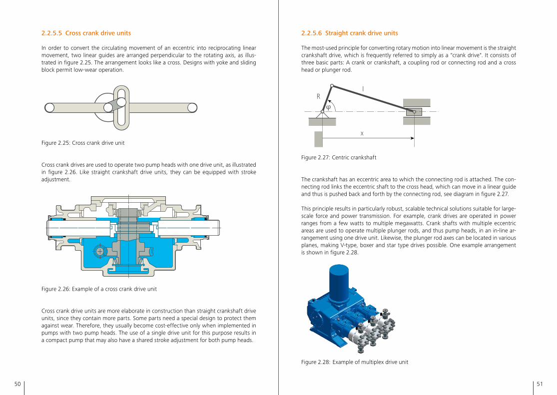
50 51
2.2.5.6 Straight crank drive units
The most-used principle for converting rotary motion into linear movement is the straight crankshaft drive, which is frequently referred to simply as a "crank drive"� It consists of three basic parts: A crank or crankshaft, a coupling rod or connecting rod and a cross head or plunger rod�
IR
x
2.2.5.6
Figure 2�27: Centric crankshaft
The crankshaft has an eccentric area to which the connecting rod is attached� The con-necting rod links the eccentric shaft to the cross head, which can move in a linear guide and thus is pushed back and forth by the connecting rod, see diagram in figure 2�27�
This principle results in particularly robust, scalable technical solutions suitable for large-scale force and power transmission� For example, crank drives are operated in power ranges from a few watts to multiple megawatts� Crank shafts with multiple eccentric areas are used to operate multiple plunger rods, and thus pump heads, in an in-line ar-rangement using one drive unit� Likewise, the plunger rod axes can be located in various planes, making V-type, boxer and star type drives possible� One example arrangement is shown in figure 2�28�
Figure 2�28: Example of multiplex drive unit
2.2.5.5 Cross crank drive units
In order to convert the circulating movement of an eccentric into reciprocating linear movement, two linear guides are arranged perpendicular to the rotating axis, as illus-trated in figure 2�25� The arrangement looks like a cross� Designs with yoke and sliding block permit low-wear operation�
2.27
Figure 2�25: Cross crank drive unit
Cross crank drives are used to operate two pump heads with one drive unit, as illustrated in figure 2�26� Like straight crankshaft drive units, they can be equipped with stroke adjustment�
2.28
Figure 2�26: Example of a cross crank drive unit
Cross crank drive units are more elaborate in construction than straight crankshaft drive units, since they contain more parts� Some parts need a special design to protect them against wear� Therefore, they usually become cost-effective only when implemented in pumps with two pump heads� The use of a single drive unit for this purpose results in a compact pump that may also have a shared stroke adjustment for both pump heads�
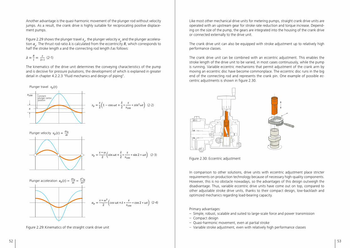
52 53
Like most other mechanical drive units for metering pumps, straight crank drive units are operated with an upstream gear for stroke rate reduction and torque increase� Depend-ing on the size of the pump, the gears are integrated into the housing of the crank drive or connected externally to the drive unit�
The crank drive unit can also be equipped with stroke adjustment up to relatively high performance classes�
The crank drive unit can be combined with an eccentric adjustment� This enables the stroke length of the drive unit to be varied, in most cases continuously, while the pump is running� Variable eccentric mechanisms that permit adjustment of the crank arm by moving an eccentric disc have become commonplace� The eccentric disc runs in the big end of the connecting rod and represents the crank pin� One example of possible ec-centric adjustments is shown in figure 2�30�
2.30 2.30
Figure 2�30: Eccentric adjustment
In comparison to other solutions, drive units with eccentric adjustment place stricter requirements on production technology because of necessary high-quality components� However, this is no obstacle nowadays, so the advantages of this design outweigh the disadvantage� Thus, variable eccentric drive units have come out on top, compared to other adjustable stroke drive units, thanks to their compact design, low-backlash and optimized mechanics regarding load-bearing capacity�
Primary advantages:– Simple, robust, scalable and suited to large-scale force and power transmission– Compact design– Quasi-harmonic movement, even at partial stroke– Variable stroke adjustment, even with relatively high performance classes
Another advantage is the quasi-harmonic movement of the plunger rod without velocity jumps� As a result, the crank drive is highly suitable for reciprocating positive displace-ment pumps�
Figure 2�29 shows the plunger travel sp , the plunger velocity vp and the plunger accelera-tion ap � The thrust rod ratio λ is calculated from the eccentricity R, which corresponds to half the stroke length s and the connecting rod length l as follows:
(2-1)
The kinematics of the drive unit determines the conveying characteristics of the pump and is decisive for pressure pulsations, the development of which is explained in greater detail in chapter 4�2�2�3 "Fluid mechanics and design of piping"�
constantplunger centreposition
Plunger travel
Plunger velocity
Plunger acceleration
(2-2)
(2-3)
(2-4)
2.29
Figure 2�29: Kinematics of the straight crank drive unit
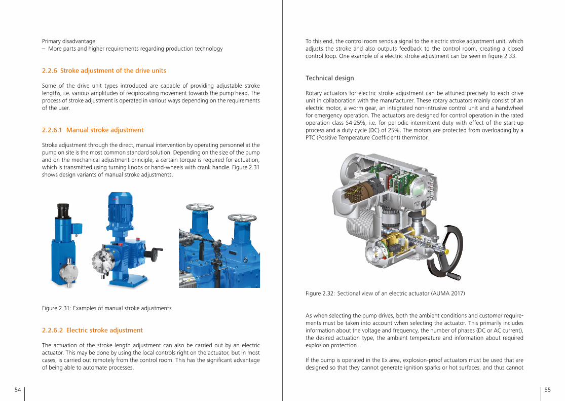
54 55
To this end, the control room sends a signal to the electric stroke adjustment unit, which adjusts the stroke and also outputs feedback to the control room, creating a closed control loop� One example of a electric stroke adjustment can be seen in figure 2�33�
Technical design
Rotary actuators for electric stroke adjustment can be attuned precisely to each drive unit in collaboration with the manufacturer� These rotary actuators mainly consist of an electric motor, a worm gear, an integrated non-intrusive control unit and a handwheel for emergency operation� The actuators are designed for control operation in the rated operation class S4-25%, i�e� for periodic intermittent duty with effect of the start-up process and a duty cycle (DC) of 25%� The motors are protected from overloading by a PTC (Positive Temperature Coefficient) thermistor�
Figure 2�32: Sectional view of an electric actuator (AUMA 2017)
As when selecting the pump drives, both the ambient conditions and customer require-ments must be taken into account when selecting the actuator� This primarily includes information about the voltage and frequency, the number of phases (DC or AC current), the desired actuation type, the ambient temperature and information about required explosion protection�
If the pump is operated in the Ex area, explosion-proof actuators must be used that are designed so that they cannot generate ignition sparks or hot surfaces, and thus cannot
Primary disadvantage:– More parts and higher requirements regarding production technology
2.2.6 Stroke adjustment of the drive units
Some of the drive unit types introduced are capable of providing adjustable stroke lengths, i�e� various amplitudes of reciprocating movement towards the pump head� The process of stroke adjustment is operated in various ways depending on the requirements of the user�
2.2.6.1 Manual stroke adjustment
Stroke adjustment through the direct, manual intervention by operating personnel at the pump on site is the most common standard solution� Depending on the size of the pump and on the mechanical adjustment principle, a certain torque is required for actuation, which is transmitted using turning knobs or hand-wheels with crank handle� Figure 2�31 shows design variants of manual stroke adjustments�
Figure 2�31: Examples of manual stroke adjustments
2.2.6.2 Electric stroke adjustment
The actuation of the stroke length adjustment can also be carried out by an electric actuator� This may be done by using the local controls right on the actuator, but in most cases, is carried out remotely from the control room� This has the significant advantage of being able to automate processes�
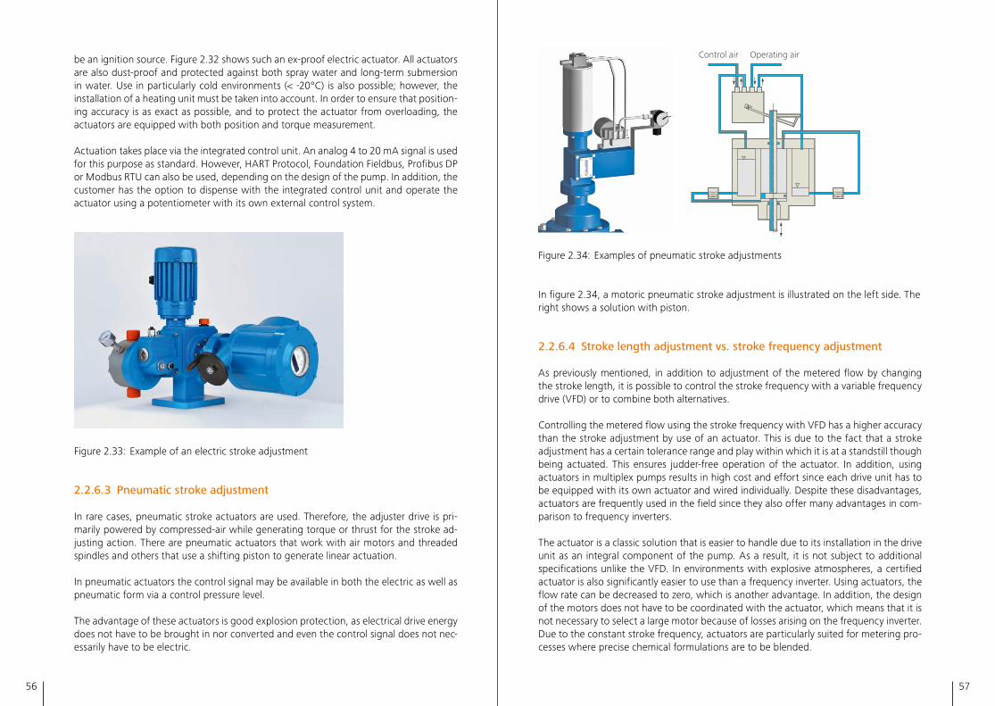
56 57
Control air Operating air
2.34
Figure 2.34: Examples of pneumatic stroke adjustments
In figure 2.34, a motoric pneumatic stroke adjustment is illustrated on the left side. The right shows a solution with piston.
2.2.6.4 Stroke length adjustment vs. stroke frequency adjustment
As previously mentioned, in addition to adjustment of the metered flow by changing the stroke length, it is possible to control the stroke frequency with a variable frequency drive (VFD) or to combine both alternatives.
Controlling the metered flow using the stroke frequency with VFD has a higher accuracy than the stroke adjustment by use of an actuator. This is due to the fact that a stroke adjustment has a certain tolerance range and play within which it is at a standstill though being actuated. This ensures judder-free operation of the actuator. In addition, using actuators in multiplex pumps results in high cost and effort since each drive unit has to be equipped with its own actuator and wired individually. Despite these disadvantages, actuators are frequently used in the field since they also offer many advantages in com-parison to frequency inverters.
The actuator is a classic solution that is easier to handle due to its installation in the drive unit as an integral component of the pump. As a result, it is not subject to additional specifications unlike the VFD. In environments with explosive atmospheres, a certified actuator is also significantly easier to use than a frequency inverter. Using actuators, the flow rate can be decreased to zero, which is another advantage. In addition, the design of the motors does not have to be coordinated with the actuator, which means that it is not necessary to select a large motor because of losses arising on the frequency inverter. Due to the constant stroke frequency, actuators are particularly suited for metering pro-cesses where precise chemical formulations are to be blended.
be an ignition source. Figure 2.32 shows such an ex-proof electric actuator. All actuators are also dust-proof and protected against both spray water and long-term submersion in water. Use in particularly cold environments (< -20°C) is also possible; however, the installation of a heating unit must be taken into account. In order to ensure that position-ing accuracy is as exact as possible, and to protect the actuator from overloading, the actuators are equipped with both position and torque measurement.
Actuation takes place via the integrated control unit. An analog 4 to 20 mA signal is used for this purpose as standard. However, HART Protocol, Foundation Fieldbus, Profibus DP or Modbus RTU can also be used, depending on the design of the pump. In addition, the customer has the option to dispense with the integrated control unit and operate the actuator using a potentiometer with its own external control system.
Figure 2.33: Example of an electric stroke adjustment
2.2.6.3 Pneumatic stroke adjustment
In rare cases, pneumatic stroke actuators are used. Therefore, the adjuster drive is pri-marily powered by compressed-air while generating torque or thrust for the stroke ad-justing action. There are pneumatic actuators that work with air motors and threaded spindles and others that use a shifting piston to generate linear actuation.
In pneumatic actuators the control signal may be available in both the electric as well as pneumatic form via a control pressure level.
The advantage of these actuators is good explosion protection, as electrical drive energy does not have to be brought in nor converted and even the control signal does not nec-essarily have to be electric.
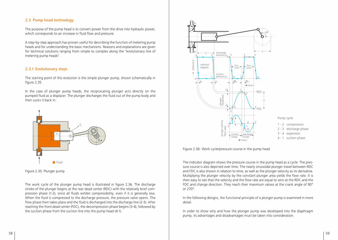
58 59
p2
p1s
s
s
pres
sure
p
ωt
3 3 32 2dischargepressure p2
suctionpressure p14
se sc
s eplun
ger
mov
emen
tpl
unge
r ve
loci
ty(fl
ow r
ate)
s c
Δte Δtc
1 14
4
v4
3
3
2
1
suctionstroke
dischargestroke
3
3
time t
4
12
indicatordiagram
time t
flow-phase
RDC
FDC
Pump cycle
1 - 2 compression2 - 3 discharge phase3 - 4 expansion4 - 1 suction phase
flow-phase
v
2.36
Figure 2�36: Work cycle/pressure course in the pump head
The indicator diagram shows the pressure course in the pump head as a cycle� The pres-sure course is also depicted over time� The nearly sinusoidal plunger travel between RDC and FDC is also shown in relation to time, as well as the plunger velocity as its derivative� Multiplying the plunger velocity by the constant plunger area yields the flow rate� It is then easy to see that the velocity and the flow rate are equal to zero at the RDC and the FDC and change direction� They reach their maximum values at the crank angle of 90° or 270°�
In the following designs, the functional principle of a plunger pump is examined in more detail�
In order to show why and how the plunger pump was developed into the diaphragm pump, its advantages and disadvantages must be taken into consideration�
2.3 Pump head technology
The purpose of the pump head is to convert power from the drive into hydraulic power, which corresponds to an increase in fluid flow and pressure�
A step-by-step approach has proven useful for describing the function of metering pump heads and for understanding the basic mechanisms� Reasons and explanations are given for technical solutions ranging from simple to complex along the "evolutionary line of metering pump heads"�
2.3.1 Evolutionary steps
The starting point of this evolution is the simple plunger pump, shown schematically in figure 2�35�
In the case of plunger pump heads, the reciprocating plunger acts directly on the pumped fluid as a displacer� The plunger discharges the fluid out of the pump body and then sucks it back in�
Fluid
VSR
VL
.
D
Figure 2�35: Plunger pump
The work cycle of the plunger pump head is illustrated in figure 2�36� The discharge stroke of the plunger begins at the rear dead center (RDC) with the relatively brief com-pression phase (1-2), since all fluids exhibit compressibility, even if it is generally low� When the fluid is compressed to the discharge pressure, the pressure valve opens� The flow phase then takes place and the fluid is discharged into the discharge line (2-3)� After reaching the front dead center (FDC), the decompression phase begins (3-4), followed by the suction phase from the suction line into the pump head (4-1)�
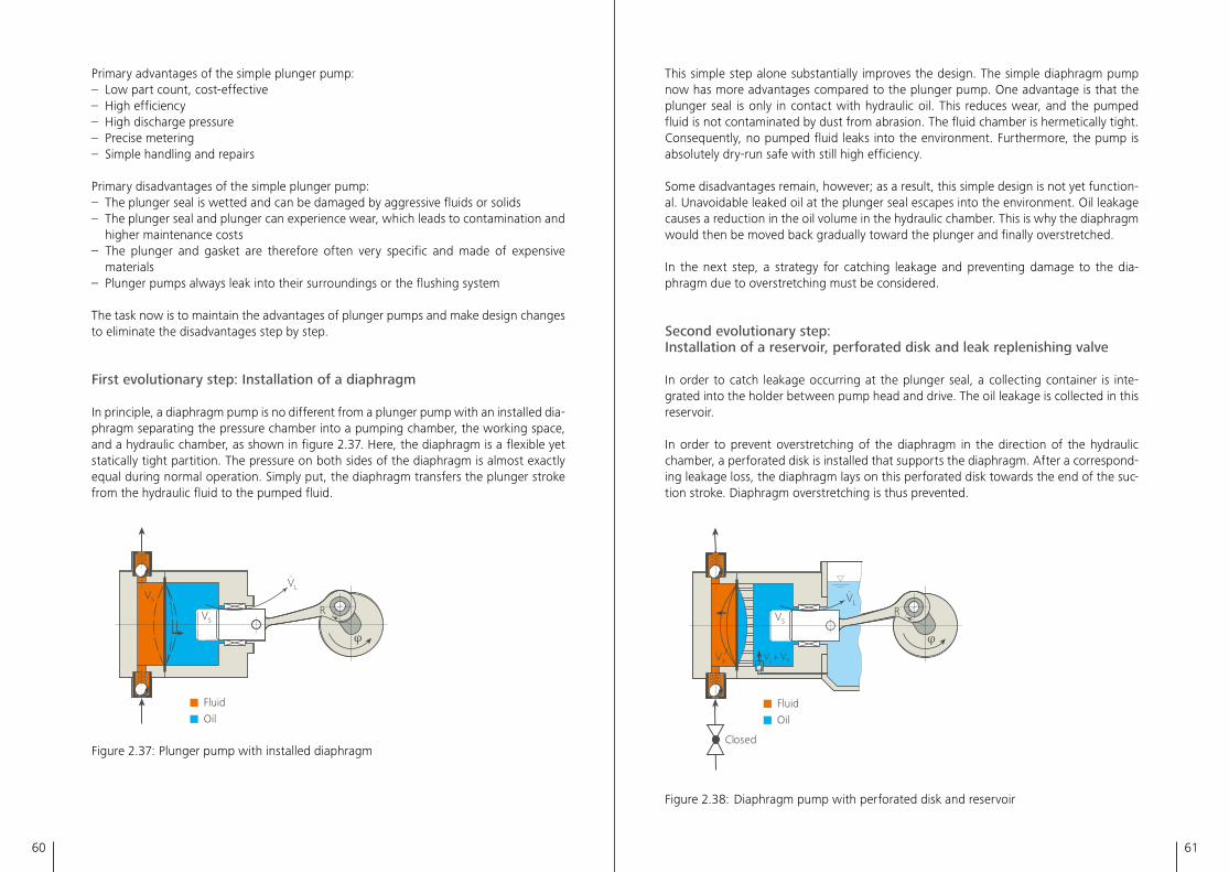
60 61
This simple step alone substantially improves the design� The simple diaphragm pump now has more advantages compared to the plunger pump� One advantage is that the plunger seal is only in contact with hydraulic oil� This reduces wear, and the pumped fluid is not contaminated by dust from abrasion� The fluid chamber is hermetically tight� Consequently, no pumped fluid leaks into the environment� Furthermore, the pump is absolutely dry-run safe with still high efficiency�
Some disadvantages remain, however; as a result, this simple design is not yet function-al� Unavoidable leaked oil at the plunger seal escapes into the environment� Oil leakage causes a reduction in the oil volume in the hydraulic chamber� This is why the diaphragm would then be moved back gradually toward the plunger and finally overstretched�
In the next step, a strategy for catching leakage and preventing damage to the dia-phragm due to overstretching must be considered�
Second evolutionary step: Installation of a reservoir, perforated disk and leak replenishing valve
In order to catch leakage occurring at the plunger seal, a collecting container is inte-grated into the holder between pump head and drive� The oil leakage is collected in this reservoir�
In order to prevent overstretching of the diaphragm in the direction of the hydraulic chamber, a perforated disk is installed that supports the diaphragm� After a correspond-ing leakage loss, the diaphragm lays on this perforated disk towards the end of the suc-tion stroke� Diaphragm overstretching is thus prevented�
Closed
Fluid Oil
RVL
.
VX
.+VL
.VX
.
VS
2.38
Figure 2�38: Diaphragm pump with perforated disk and reservoir
Primary advantages of the simple plunger pump:– Low part count, cost-effective– High efficiency– High discharge pressure– Precise metering– Simple handling and repairs
Primary disadvantages of the simple plunger pump:– The plunger seal is wetted and can be damaged by aggressive fluids or solids– The plunger seal and plunger can experience wear, which leads to contamination and
higher maintenance costs– The plunger and gasket are therefore often very specific and made of expensive
materials– Plunger pumps always leak into their surroundings or the flushing system
The task now is to maintain the advantages of plunger pumps and make design changes to eliminate the disadvantages step by step�
First evolutionary step: Installation of a diaphragm
In principle, a diaphragm pump is no different from a plunger pump with an installed dia-phragm separating the pressure chamber into a pumping chamber, the working space, and a hydraulic chamber, as shown in figure 2�37� Here, the diaphragm is a flexible yet statically tight partition� The pressure on both sides of the diaphragm is almost exactly equal during normal operation� Simply put, the diaphragm transfers the plunger stroke from the hydraulic fluid to the pumped fluid�
Fluid Oil
VSR
VS
VL
.
2.37
Figure 2�37: Plunger pump with installed diaphragm
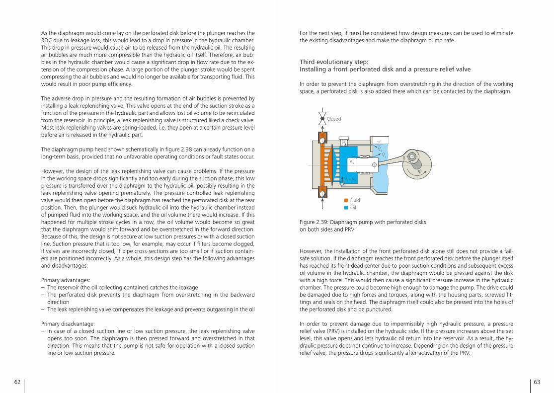
62 63
For the next step, it must be considered how design measures can be used to eliminate the existing disadvantages and make the diaphragm pump safe�
Third evolutionary step: Installing a front perforated disk and a pressure relief valve
In order to prevent the diaphragm from overstretching in the direction of the working space, a perforated disk is also added there which can be contacted by the diaphragm�
Closed
Fluid
Oil
RVL
.VY
.
VS
+VL
.VX
.
2.39
Figure 2�39: Diaphragm pump with perforated disks on both sides and PRV
However, the installation of the front perforated disk alone still does not provide a fail-safe solution� If the diaphragm reaches the front perforated disk before the plunger itself has reached its front dead center due to poor suction conditions and subsequent excess oil volume in the hydraulic chamber, the diaphragm would be pressed against the disk with a high force� This would then cause a significant pressure increase in the hydraulic chamber� The pressure could become high enough to damage the pump� The drive could be damaged due to high forces and torques, along with the housing parts, screwed fit-tings and seals on the head� The diaphragm itself could also be pressed into the holes of the perforated disk and be punctured�
In order to prevent damage due to impermissibly high hydraulic pressure, a pressure relief valve (PRV) is installed on the hydraulic side� If the pressure increases above the set level, this valve opens and lets hydraulic oil return into the reservoir� As a result, the hy-draulic pressure does not continue to increase� Depending on the design of the pressure relief valve, the pressure drops significantly after activation of the PRV�
As the diaphragm would come lay on the perforated disk before the plunger reaches the RDC due to leakage loss, this would lead to a drop in pressure in the hydraulic chamber� This drop in pressure would cause air to be released from the hydraulic oil� The resulting air bubbles are much more compressible than the hydraulic oil itself� Therefore, air bub-bles in the hydraulic chamber would cause a significant drop in flow rate due to the ex-tension of the compression phase� A large portion of the plunger stroke would be spent compressing the air bubbles and would no longer be available for transporting fluid� This would result in poor pump efficiency�
The adverse drop in pressure and the resulting formation of air bubbles is prevented by installing a leak replenishing valve� This valve opens at the end of the suction stroke as a function of the pressure in the hydraulic part and allows lost oil volume to be recirculated from the reservoir� In principle, a leak replenishing valve is structured liked a check valve� Most leak replenishing valves are spring-loaded, i�e� they open at a certain pressure level before air is released in the hydraulic part�
The diaphragm pump head shown schematically in figure 2�38 can already function on a long-term basis, provided that no unfavorable operating conditions or fault states occur�
However, the design of the leak replenishing valve can cause problems� If the pressure in the working space drops significantly and too early during the suction phase, this low pressure is transferred over the diaphragm to the hydraulic oil, possibly resulting in the leak replenishing valve opening prematurely� The pressure-controlled leak replenishing valve would then open before the diaphragm has reached the perforated disk at the rear position� Then, the plunger would suck hydraulic oil into the hydraulic chamber instead of pumped fluid into the working space, and the oil volume there would increase� If this happened for multiple stroke cycles in a row, the oil volume would become so great that the diaphragm would shift forward and be overstretched in the forward direction� Because of this, the design is not secure at low suction pressures or with a closed suction line� Suction pressure that is too low, for example, may occur if filters become clogged, if valves are incorrectly closed, if pipe cross-sections are too small or if suction contain-ers are positioned incorrectly� As a whole, this design step has the following advantages and disadvantages:
Primary advantages:– The reservoir (the oil collecting container) catches the leakage– The perforated disk prevents the diaphragm from overstretching in the backward
direction– The leak replenishing valve compensates the leakage and prevents outgassing in the oil
Primary disadvantage:– In case of a closed suction line or low suction pressure, the leak replenishing valve
opens too soon� The diaphragm is then pressed forward and overstretched in that direction� This means that the pump is not safe for operation with a closed suction line or low suction pressure�
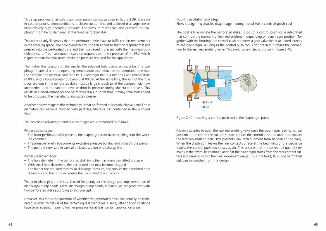
64 65
Fourth evolutionary step: New design: hydraulic diaphragm pump head with control push rod
The goal is to eliminate the perforated disks� To do so, a control push rod is integrated that controls the moment of leak replenishment depending on diaphragm position� To-gether with the housing, the control push rod forms a gate valve that is actuated directly by the diaphragm� As long as the control push rod is not pressed, it closes the connec-tion to the leak replenishing valve� This evolutionary step is shown in figure 2�40�
Fluid
Oil
RVL
.
VL
.
VL
.
2.40
Figure 2�40: Installing a control push rod in the diaphragm pump
It is only possible to open the leak replenishing valve once the diaphragm reaches its rear position at the end of the suction stroke, presses the control push rod and thus exposes the leak replenishing hole� This prevents leak replenishment from happening too early� When the diaphragm leaves the rear contact surface at the beginning of the discharge stroke, the control push rod closes again� This ensures that the correct oil quantity re-mains in the hydraulic chamber, and that the diaphragm starts from the rear contact sur-face and remains within the ideal movement range� Thus, the front, fluid-side perforated disk can be omitted from this design�
This step provides a fail-safe diaphragm pump design, as seen in figure 2�39� It is safe in case of poor suction conditions, a closed suction line and a closed discharge line or impermissibly high operating pressure� The pressure relief valve also protects the dia-phragm from being damaged at the front perforated disk�
This point clearly illustrates that the perforated disks have to fulfill certain requirements in the working space� The hole diameters must be designed so that the diaphragm is not pressed into the perforated disks and then damaged if pressed with the maximum pos-sible pressure� This maximum pressure corresponds to the set pressure of the PRV, which is greater than the maximum discharge pressure required for the application�
The higher this pressure is, the smaller the selected hole diameters must be� The dia-phragm material and the operating temperature also influence the permitted hole size� For example, the pressure limit for a PTFE diaphragm that is 1 mm thick at a temperature of 80°C and a hole diameter of 2 mm is at 80 bar� At the same time, the sum of the hole cross-sections in the perforated disks must be large enough to let the pumped fluid flow unimpeded, and to avoid an adverse drop in pressure during the suction phase� This results in a disadvantage for the perforated disks in so far that, if many small holes need to be produced, the manufacturing costs increase�
Another disadvantage of this technology is that perforated disks with relatively small hole diameters can become clogged with particles, fibers or dirt contained in the pumped fluid�
The described advantages and disadvantages are summarized as follows:
Primary advantages:– The front perforated disk prevents the diaphragm from overstretching into the work-
ing chamber– The pressure relief valve prevents excessive pressure buildup and protects the pump– The pump is now safe in case of a closed suction or discharge line
Primary disadvantages:– The hole diameter in the perforated disk limits the maximum permitted pressure– With small hole diameters, the perforated disk may become clogged– The higher the required maximum discharge pressure, the smaller the permitted hole
diameters and the more expensive the perforated disks become
The principle at play in this step is used frequently for the design and implementation of diaphragm pump heads� Metal diaphragm pump heads, in particular, are produced with two perforated disks according to this concept�
However, this raises the question of whether the perforated disks can actually be elimi-nated in order to get rid of the remaining disadvantages� Hence, other design solutions have been sought, meaning further progress for at least certain application areas�
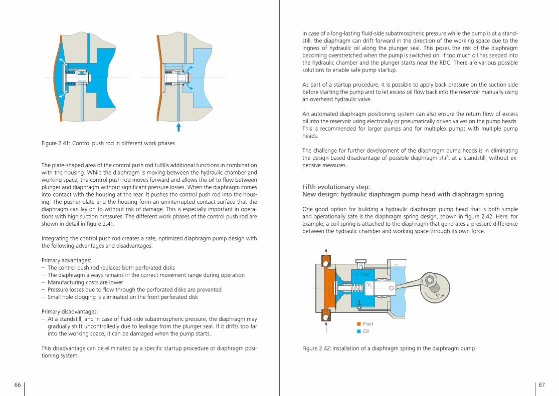
66 67
In case of a long-lasting fluid-side subatmospheric pressure while the pump is at a stand-still, the diaphragm can drift forward in the direction of the working space due to the ingress of hydraulic oil along the plunger seal� This poses the risk of the diaphragm becoming overstretched when the pump is switched on, if too much oil has seeped into the hydraulic chamber and the plunger starts near the RDC� There are various possible solutions to enable safe pump startup�
As part of a startup procedure, it is possible to apply back pressure on the suction side before starting the pump and to let excess oil flow back into the reservoir manually using an overhead hydraulic valve�
An automated diaphragm positioning system can also ensure the return flow of excess oil into the reservoir using electrically or pneumatically driven valves on the pump heads� This is recommended for larger pumps and for multiplex pumps with multiple pump heads�
The challenge for further development of the diaphragm pump heads is in eliminating the design-based disadvantage of possible diaphragm shift at a standstill, without ex-pensive measures�
Fifth evolutionary step: New design: hydraulic diaphragm pump head with diaphragm spring
One good option for building a hydraulic diaphragm pump head that is both simple and operationally safe is the diaphragm spring design, shown in figure 2�42� Here, for example, a coil spring is attached to the diaphragm that generates a pressure difference between the hydraulic chamber and working space through its own force�
Fluid
Oil
VSR
+ 1 bar
2.42
Figure 2�42: Installation of a diaphragm spring in the diaphragm pump
Figure 2�41: Control push rod in different work phases
The plate-shaped area of the control push rod fulfills additional functions in combination with the housing� While the diaphragm is moving between the hydraulic chamber and working space, the control push rod moves forward and allows the oil to flow between plunger and diaphragm without significant pressure losses� When the diaphragm comes into contact with the housing at the rear, it pushes the control push rod into the hous-ing� The pusher plate and the housing form an uninterrupted contact surface that the diaphragm can lay on to without risk of damage� This is especially important in opera-tions with high suction pressures� The different work phases of the control push rod are shown in detail in figure 2�41�
Integrating the control push rod creates a safe, optimized diaphragm pump design with the following advantages and disadvantages:
Primary advantages:– The control push rod replaces both perforated disks– The diaphragm always remains in the correct movement range during operation– Manufacturing costs are lower– Pressure losses due to flow through the perforated disks are prevented– Small hole clogging is eliminated on the front perforated disk
Primary disadvantages:– At a standstill, and in case of fluid-side subatmospheric pressure, the diaphragm may
gradually shift uncontrolledly due to leakage from the plunger seal� If it drifts too far into the working space, it can be damaged when the pump starts�
This disadvantage can be eliminated by a specific startup procedure or diaphragm posi-tioning system�
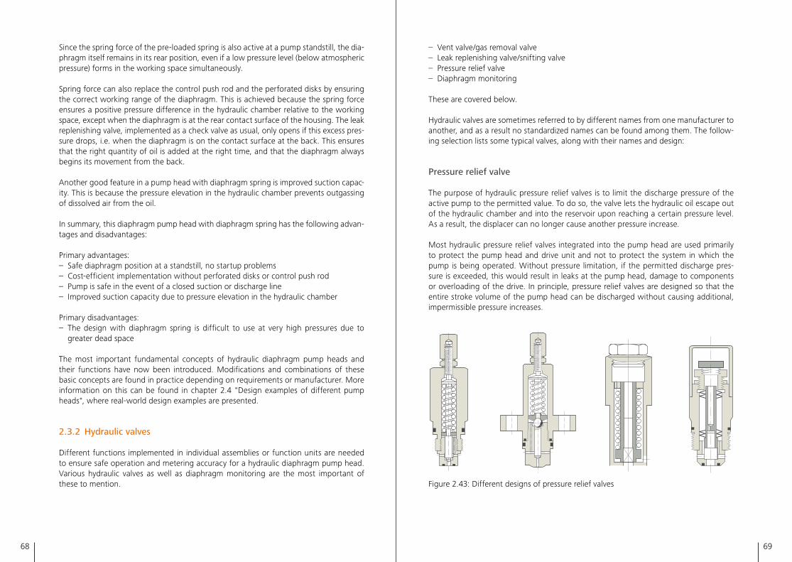
68 69
– Vent valve/gas removal valve– Leak replenishing valve/snifting valve– Pressure relief valve– Diaphragm monitoring
These are covered below�
Hydraulic valves are sometimes referred to by different names from one manufacturer to another, and as a result no standardized names can be found among them� The follow-ing selection lists some typical valves, along with their names and design:
Pressure relief valve
The purpose of hydraulic pressure relief valves is to limit the discharge pressure of the active pump to the permitted value� To do so, the valve lets the hydraulic oil escape out of the hydraulic chamber and into the reservoir upon reaching a certain pressure level� As a result, the displacer can no longer cause another pressure increase�
Most hydraulic pressure relief valves integrated into the pump head are used primarily to protect the pump head and drive unit and not to protect the system in which the pump is being operated� Without pressure limitation, if the permitted discharge pres-sure is exceeded, this would result in leaks at the pump head, damage to components or overloading of the drive� In principle, pressure relief valves are designed so that the entire stroke volume of the pump head can be discharged without causing additional, impermissible pressure increases�
2.43
Figure 2�43: Different designs of pressure relief valves
Since the spring force of the pre-loaded spring is also active at a pump standstill, the dia-phragm itself remains in its rear position, even if a low pressure level (below atmospheric pressure) forms in the working space simultaneously�
Spring force can also replace the control push rod and the perforated disks by ensuring the correct working range of the diaphragm� This is achieved because the spring force ensures a positive pressure difference in the hydraulic chamber relative to the working space, except when the diaphragm is at the rear contact surface of the housing� The leak replenishing valve, implemented as a check valve as usual, only opens if this excess pres-sure drops, i�e� when the diaphragm is on the contact surface at the back� This ensures that the right quantity of oil is added at the right time, and that the diaphragm always begins its movement from the back�
Another good feature in a pump head with diaphragm spring is improved suction capac-ity� This is because the pressure elevation in the hydraulic chamber prevents outgassing of dissolved air from the oil�
In summary, this diaphragm pump head with diaphragm spring has the following advan-tages and disadvantages:
Primary advantages:– Safe diaphragm position at a standstill, no startup problems– Cost-efficient implementation without perforated disks or control push rod– Pump is safe in the event of a closed suction or discharge line– Improved suction capacity due to pressure elevation in the hydraulic chamber
Primary disadvantages:– The design with diaphragm spring is difficult to use at very high pressures due to
greater dead space
The most important fundamental concepts of hydraulic diaphragm pump heads and their functions have now been introduced� Modifications and combinations of these basic concepts are found in practice depending on requirements or manufacturer� More information on this can be found in chapter 2�4 "Design examples of different pump heads", where real-world design examples are presented�
2.3.2 Hydraulic valves
Different functions implemented in individual assemblies or function units are needed to ensure safe operation and metering accuracy for a hydraulic diaphragm pump head� Various hydraulic valves as well as diaphragm monitoring are the most important of these to mention�
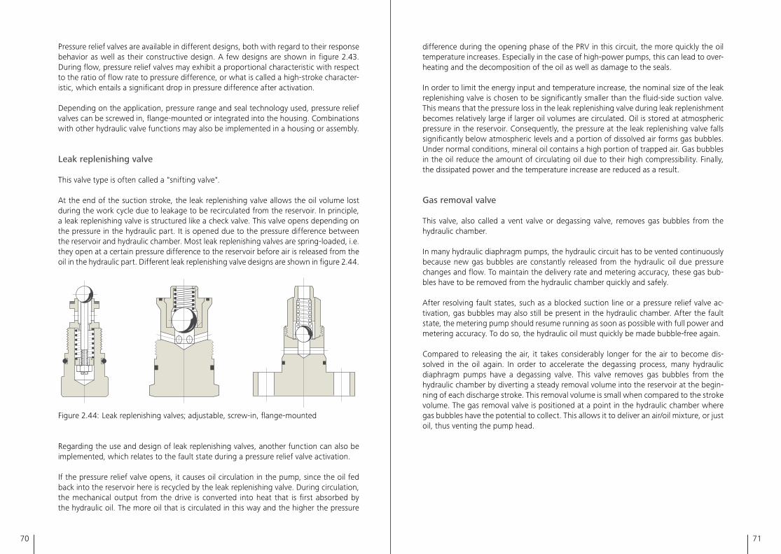
70 71
difference during the opening phase of the PRV in this circuit, the more quickly the oil temperature increases� Especially in the case of high-power pumps, this can lead to over-heating and the decomposition of the oil as well as damage to the seals�
In order to limit the energy input and temperature increase, the nominal size of the leak replenishing valve is chosen to be significantly smaller than the fluid-side suction valve� This means that the pressure loss in the leak replenishing valve during leak replenishment becomes relatively large if larger oil volumes are circulated� Oil is stored at atmospheric pressure in the reservoir� Consequently, the pressure at the leak replenishing valve falls significantly below atmospheric levels and a portion of dissolved air forms gas bubbles� Under normal conditions, mineral oil contains a high portion of trapped air� Gas bubbles in the oil reduce the amount of circulating oil due to their high compressibility� Finally, the dissipated power and the temperature increase are reduced as a result�
Gas removal valve
This valve, also called a vent valve or degassing valve, removes gas bubbles from the hydraulic chamber�
In many hydraulic diaphragm pumps, the hydraulic circuit has to be vented continuously because new gas bubbles are constantly released from the hydraulic oil due pressure changes and flow� To maintain the delivery rate and metering accuracy, these gas bub-bles have to be removed from the hydraulic chamber quickly and safely�
After resolving fault states, such as a blocked suction line or a pressure relief valve ac-tivation, gas bubbles may also still be present in the hydraulic chamber� After the fault state, the metering pump should resume running as soon as possible with full power and metering accuracy� To do so, the hydraulic oil must quickly be made bubble-free again�
Compared to releasing the air, it takes considerably longer for the air to become dis-solved in the oil again� In order to accelerate the degassing process, many hydraulic diaphragm pumps have a degassing valve� This valve removes gas bubbles from the hydraulic chamber by diverting a steady removal volume into the reservoir at the begin-ning of each discharge stroke� This removal volume is small when compared to the stroke volume� The gas removal valve is positioned at a point in the hydraulic chamber where gas bubbles have the potential to collect� This allows it to deliver an air/oil mixture, or just oil, thus venting the pump head�
Pressure relief valves are available in different designs, both with regard to their response behavior as well as their constructive design� A few designs are shown in figure 2�43� During flow, pressure relief valves may exhibit a proportional characteristic with respect to the ratio of flow rate to pressure difference, or what is called a high-stroke character-istic, which entails a significant drop in pressure difference after activation�
Depending on the application, pressure range and seal technology used, pressure relief valves can be screwed in, flange-mounted or integrated into the housing� Combinations with other hydraulic valve functions may also be implemented in a housing or assembly�
Leak replenishing valve
This valve type is often called a "snifting valve"�
At the end of the suction stroke, the leak replenishing valve allows the oil volume lost during the work cycle due to leakage to be recirculated from the reservoir� In principle, a leak replenishing valve is structured like a check valve� This valve opens depending on the pressure in the hydraulic part� It is opened due to the pressure difference between the reservoir and hydraulic chamber� Most leak replenishing valves are spring-loaded, i�e� they open at a certain pressure difference to the reservoir before air is released from the oil in the hydraulic part� Different leak replenishing valve designs are shown in figure 2�44�
2.44
Figure 2�44: Leak replenishing valves; adjustable, screw-in, flange-mounted
Regarding the use and design of leak replenishing valves, another function can also be implemented, which relates to the fault state during a pressure relief valve activation�
If the pressure relief valve opens, it causes oil circulation in the pump, since the oil fed back into the reservoir here is recycled by the leak replenishing valve� During circulation, the mechanical output from the drive is converted into heat that is first absorbed by the hydraulic oil� The more oil that is circulated in this way and the higher the pressure
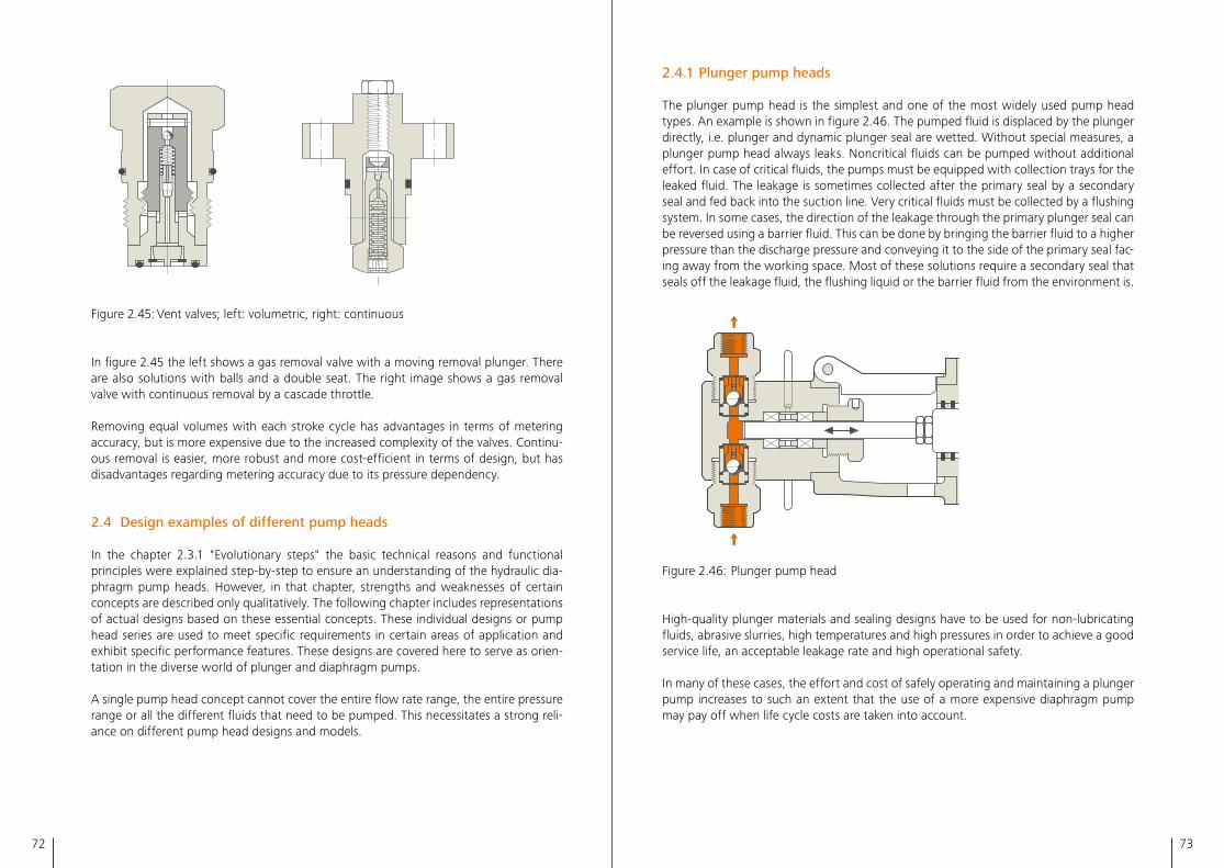
72 73
2.4.1 Plunger pump heads
The plunger pump head is the simplest and one of the most widely used pump head types� An example is shown in figure 2�46� The pumped fluid is displaced by the plunger directly, i�e� plunger and dynamic plunger seal are wetted� Without special measures, a plunger pump head always leaks� Noncritical fluids can be pumped without additional effort� In case of critical fluids, the pumps must be equipped with collection trays for the leaked fluid� The leakage is sometimes collected after the primary seal by a secondary seal and fed back into the suction line� Very critical fluids must be collected by a flushing system� In some cases, the direction of the leakage through the primary plunger seal can be reversed using a barrier fluid� This can be done by bringing the barrier fluid to a higher pressure than the discharge pressure and conveying it to the side of the primary seal fac-ing away from the working space� Most of these solutions require a secondary seal that seals off the leakage fluid, the flushing liquid or the barrier fluid from the environment is�
2.46 2.48
2.50 2.53 2.54
2.56 2.67
Figure 2�46: Plunger pump head
High-quality plunger materials and sealing designs have to be used for non-lubricating fluids, abrasive slurries, high temperatures and high pressures in order to achieve a good service life, an acceptable leakage rate and high operational safety�
In many of these cases, the effort and cost of safely operating and maintaining a plunger pump increases to such an extent that the use of a more expensive diaphragm pump may pay off when life cycle costs are taken into account�
2.45
Figure 2�45: Vent valves; left: volumetric, right: continuous
In figure 2�45 the left shows a gas removal valve with a moving removal plunger� There are also solutions with balls and a double seat� The right image shows a gas removal valve with continuous removal by a cascade throttle�
Removing equal volumes with each stroke cycle has advantages in terms of metering accuracy, but is more expensive due to the increased complexity of the valves� Continu-ous removal is easier, more robust and more cost-efficient in terms of design, but has disadvantages regarding metering accuracy due to its pressure dependency�
2.4 Design examples of different pump heads
In the chapter 2�3�1 "Evolutionary steps" the basic technical reasons and functional principles were explained step-by-step to ensure an understanding of the hydraulic dia-phragm pump heads� However, in that chapter, strengths and weaknesses of certain concepts are described only qualitatively� The following chapter includes representations of actual designs based on these essential concepts� These individual designs or pump head series are used to meet specific requirements in certain areas of application and exhibit specific performance features� These designs are covered here to serve as orien-tation in the diverse world of plunger and diaphragm pumps�
A single pump head concept cannot cover the entire flow rate range, the entire pressure range or all the different fluids that need to be pumped� This necessitates a strong reli-ance on different pump head designs and models�
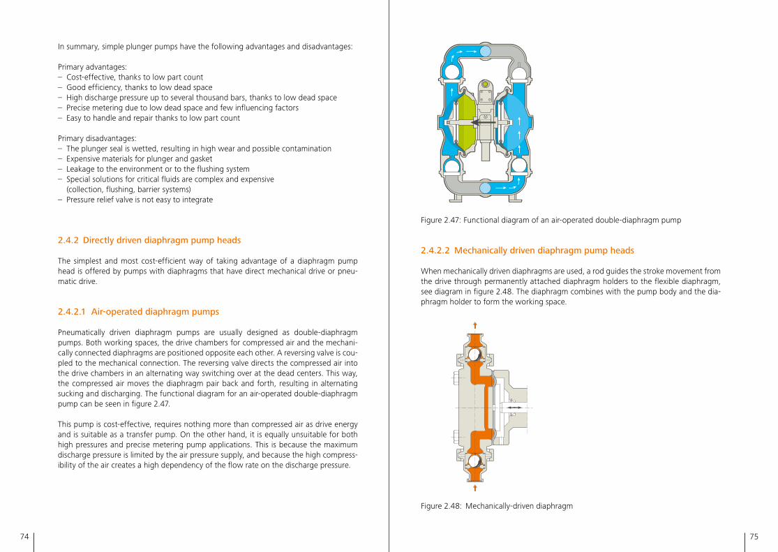
74 75
Figure 2�47: Functional diagram of an air-operated double-diaphragm pump
2.4.2.2 Mechanically driven diaphragm pump heads
When mechanically driven diaphragms are used, a rod guides the stroke movement from the drive through permanently attached diaphragm holders to the flexible diaphragm, see diagram in figure 2�48� The diaphragm combines with the pump body and the dia-phragm holder to form the working space�
2.46 2.48
2.50 2.53 2.54
2.56 2.67
Figure 2�48: Mechanically-driven diaphragm
In summary, simple plunger pumps have the following advantages and disadvantages:
Primary advantages:– Cost-effective, thanks to low part count– Good efficiency, thanks to low dead space– High discharge pressure up to several thousand bars, thanks to low dead space– Precise metering due to low dead space and few influencing factors– Easy to handle and repair thanks to low part count
Primary disadvantages:– The plunger seal is wetted, resulting in high wear and possible contamination– Expensive materials for plunger and gasket– Leakage to the environment or to the flushing system– Special solutions for critical fluids are complex and expensive
(collection, flushing, barrier systems)– Pressure relief valve is not easy to integrate
2.4.2 Directly driven diaphragm pump heads
The simplest and most cost-efficient way of taking advantage of a diaphragm pump head is offered by pumps with diaphragms that have direct mechanical drive or pneu-matic drive�
2.4.2.1 Air-operated diaphragm pumps
Pneumatically driven diaphragm pumps are usually designed as double-diaphragm pumps� Both working spaces, the drive chambers for compressed air and the mechani-cally connected diaphragms are positioned opposite each other� A reversing valve is cou-pled to the mechanical connection� The reversing valve directs the compressed air into the drive chambers in an alternating way switching over at the dead centers� This way, the compressed air moves the diaphragm pair back and forth, resulting in alternating sucking and discharging� The functional diagram for an air-operated double-diaphragm pump can be seen in figure 2�47�
This pump is cost-effective, requires nothing more than compressed air as drive energy and is suitable as a transfer pump� On the other hand, it is equally unsuitable for both high pressures and precise metering pump applications� This is because the maximum discharge pressure is limited by the air pressure supply, and because the high compress-ibility of the air creates a high dependency of the flow rate on the discharge pressure�
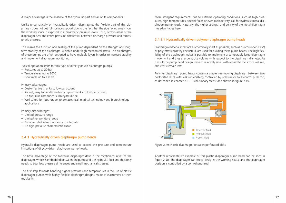
76 77
More stringent requirements due to extreme operating conditions, such as high pres-sures, high temperatures, special fluids or even radioactivity, call for hydraulic metal dia-phragm pump heads� Naturally, the higher strength and density of the metal diaphragm has advantages here�
2.4.3.1 Hydraulically driven polymer diaphragm pump heads
Diaphragm materials that are as chemically inert as possible, such as fluororubber (FKM) or polytetrafluoroethylene (PTFE), are used for building these pump heads� The high flex-ibility of the diaphragm makes it possible to implement a comparably large diaphragm movement and thus a large stroke volume with respect to the diaphragm diameter� As a result the pump head design remains relatively small with regard to the stroke volume, and costs remain low�
Polymer diaphragm pump heads contain a simple free-moving diaphragm between two perforated disks with leak replenishing controlled by pressure or by a control push rod, as described in chapter 2�3�1 "Evolutionary steps" and shown in figure 2�49�
Reservoir fluid Hydraulic fluid
Process fluid
2.49
Figure 2�49: Plastic diaphragm between perforated disks
Another representative example of this plastic diaphragm pump head can be seen in figure 2�50� The diaphragm can move freely in the working space and the diaphragm position is controlled by a control push rod�
A major advantage is the absence of the hydraulic part and all of its components�
Unlike pneumatically or hydraulically driven diaphragms, the flexible part of this dia-phragm does not get full-surface support due to the fact that the side facing away from the working space is exposed to atmospheric pressure levels� Thus, certain areas of the diaphragm bear the entire pressure differential between discharge pressure and atmos-pheric pressure�
This makes the function and sealing of the pump dependent on the strength and long-term stability of the diaphragm, which is under high mechanical stress� The diaphragms of these pumps are often designed to have multiple layers in order to increase stability and implement diaphragm monitoring�
Typical operation limits for this type of directly driven diaphragm pumps:– Pressures up to 20 bar – Temperatures up to 80°C – Flow rates up to 2 m³/h
Primary advantages:– Cost-effective, thanks to low part count– Robust, easy to handle and easy repair, thanks to low part count– No hydraulic components, no hydraulic oil– Well suited for food-grade, pharmaceutical, medical technology and biotechnology
applications
Primary disadvantages:– Limited pressure range– Limited temperature range– Pressure relief valve is not easy to integrate– No rigid pressure characteristic curve
2.4.3 Hydraulically driven diaphragm pump heads
Hydraulic diaphragm pump heads are used to exceed the pressure and temperature limitations of directly driven diaphragm pump heads�
The basic advantage of the hydraulic diaphragm drive is the mechanical relief of the diaphragm, which is embedded between the pump and the hydraulic fluid and thus only needs to bear low pressure differences and small mechanical stresses�
The first step towards handling higher pressures and temperatures is the use of plastic diaphragm pumps with highly flexible diaphragm designs made of elastomers or ther-moplastics�
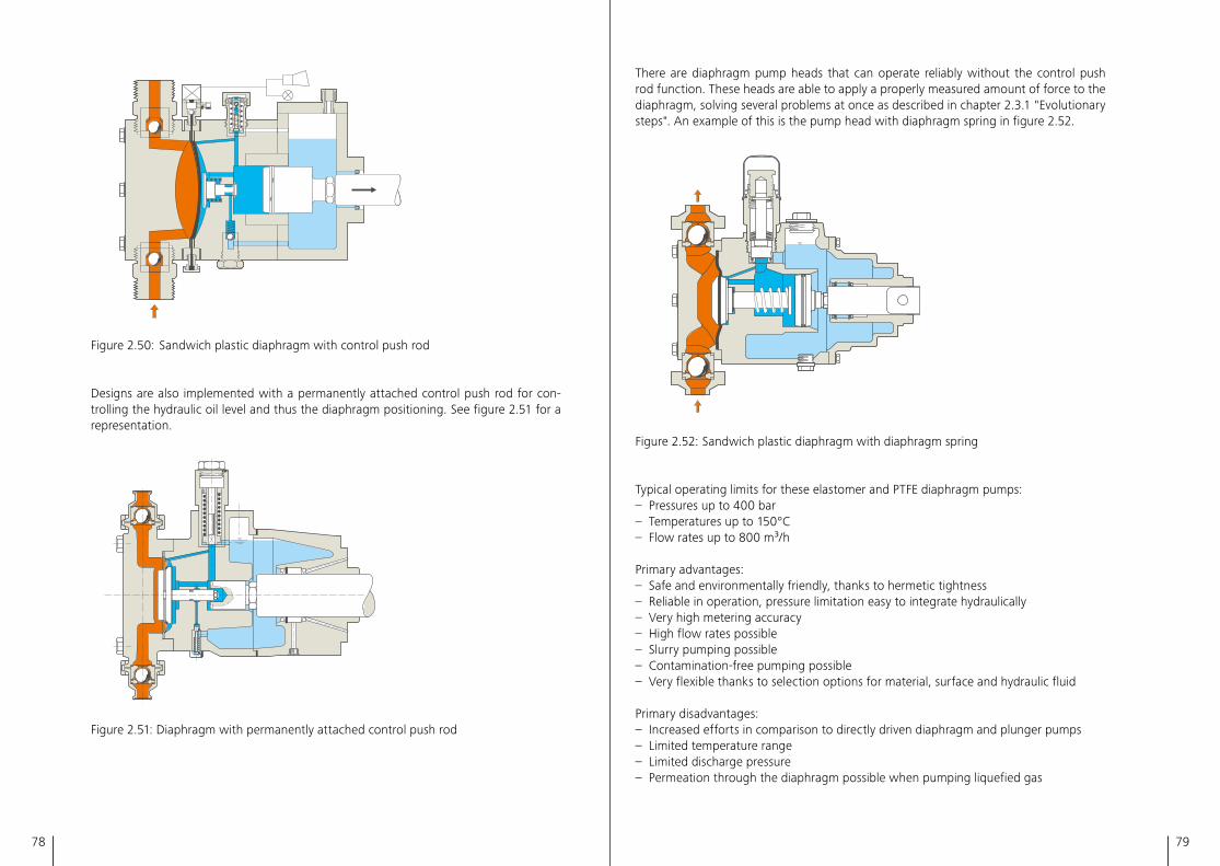
78 79
There are diaphragm pump heads that can operate reliably without the control push rod function� These heads are able to apply a properly measured amount of force to the diaphragm, solving several problems at once as described in chapter 2�3�1 "Evolutionary steps"� An example of this is the pump head with diaphragm spring in figure 2�52�
2.46 2.48
2.50 2.53 2.54
2.56 2.67
Figure 2�52: Sandwich plastic diaphragm with diaphragm spring
Typical operating limits for these elastomer and PTFE diaphragm pumps:– Pressures up to 400 bar– Temperatures up to 150°C– Flow rates up to 800 m³/h
Primary advantages:– Safe and environmentally friendly, thanks to hermetic tightness– Reliable in operation, pressure limitation easy to integrate hydraulically– Very high metering accuracy– High flow rates possible– Slurry pumping possible– Contamination-free pumping possible– Very flexible thanks to selection options for material, surface and hydraulic fluid
Primary disadvantages:– Increased efforts in comparison to directly driven diaphragm and plunger pumps– Limited temperature range– Limited discharge pressure– Permeation through the diaphragm possible when pumping liquefied gas
2.46 2.48
2.50 2.53 2.54
2.56 2.67
Figure 2�50: Sandwich plastic diaphragm with control push rod
Designs are also implemented with a permanently attached control push rod for con-trolling the hydraulic oil level and thus the diaphragm positioning� See figure 2�51 for a representation�
2.52
Figure 2�51: Diaphragm with permanently attached control push rod
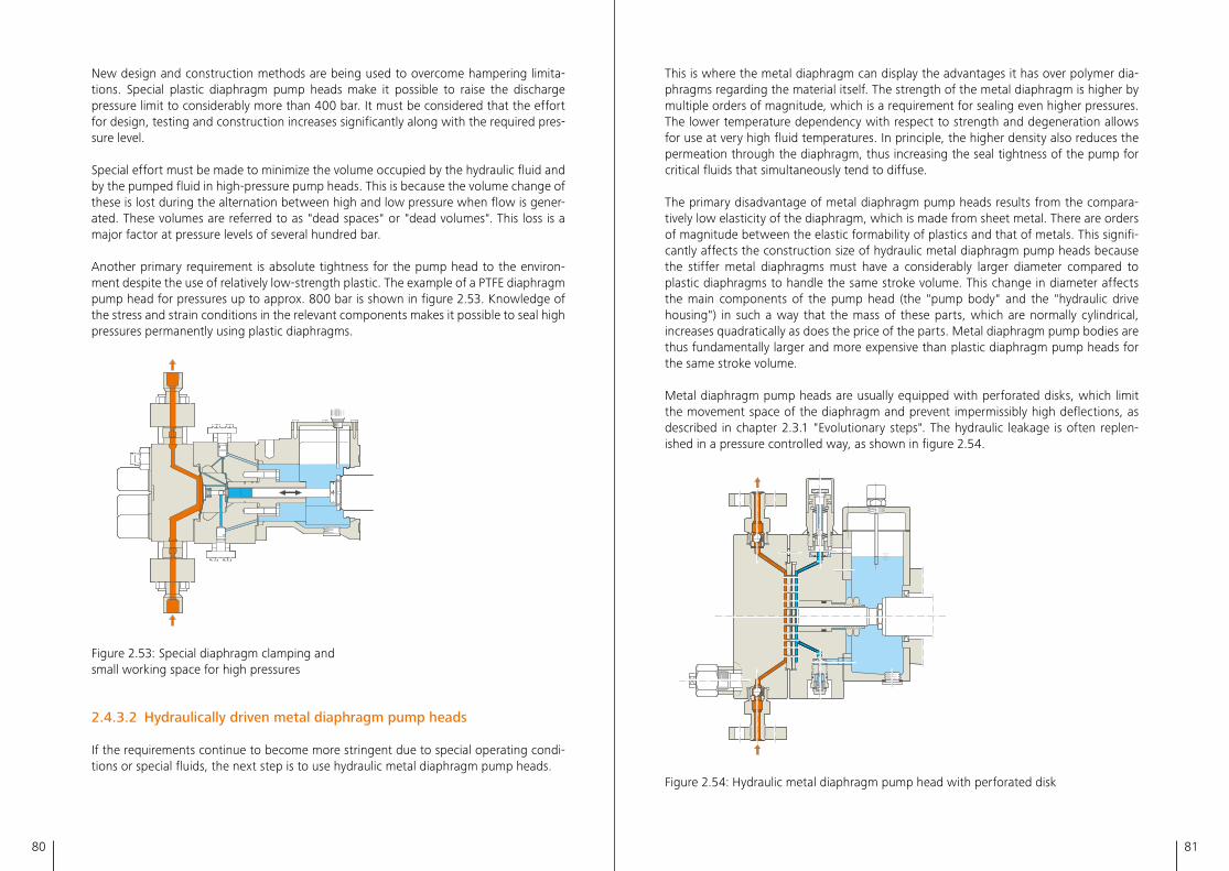
80 81
This is where the metal diaphragm can display the advantages it has over polymer dia-phragms regarding the material itself� The strength of the metal diaphragm is higher by multiple orders of magnitude, which is a requirement for sealing even higher pressures� The lower temperature dependency with respect to strength and degeneration allows for use at very high fluid temperatures� In principle, the higher density also reduces the permeation through the diaphragm, thus increasing the seal tightness of the pump for critical fluids that simultaneously tend to diffuse�
The primary disadvantage of metal diaphragm pump heads results from the compara-tively low elasticity of the diaphragm, which is made from sheet metal� There are orders of magnitude between the elastic formability of plastics and that of metals� This signifi-cantly affects the construction size of hydraulic metal diaphragm pump heads because the stiffer metal diaphragms must have a considerably larger diameter compared to plastic diaphragms to handle the same stroke volume� This change in diameter affects the main components of the pump head (the "pump body" and the "hydraulic drive housing") in such a way that the mass of these parts, which are normally cylindrical, increases quadratically as does the price of the parts� Metal diaphragm pump bodies are thus fundamentally larger and more expensive than plastic diaphragm pump heads for the same stroke volume�
Metal diaphragm pump heads are usually equipped with perforated disks, which limit the movement space of the diaphragm and prevent impermissibly high deflections, as described in chapter 2�3�1 "Evolutionary steps"� The hydraulic leakage is often replen-ished in a pressure controlled way, as shown in figure 2�54� 2.55
Figure 2�54: Hydraulic metal diaphragm pump head with perforated disk
New design and construction methods are being used to overcome hampering limita-tions� Special plastic diaphragm pump heads make it possible to raise the discharge pressure limit to considerably more than 400 bar� It must be considered that the effort for design, testing and construction increases significantly along with the required pres-sure level�
Special effort must be made to minimize the volume occupied by the hydraulic fluid and by the pumped fluid in high-pressure pump heads� This is because the volume change of these is lost during the alternation between high and low pressure when flow is gener-ated� These volumes are referred to as "dead spaces" or "dead volumes"� This loss is a major factor at pressure levels of several hundred bar�
Another primary requirement is absolute tightness for the pump head to the environ-ment despite the use of relatively low-strength plastic� The example of a PTFE diaphragm pump head for pressures up to approx� 800 bar is shown in figure 2�53� Knowledge of the stress and strain conditions in the relevant components makes it possible to seal high pressures permanently using plastic diaphragms�
2.46 2.48
2.50 2.53 2.54
2.56 2.67
Figure 2�53: Special diaphragm clamping and small working space for high pressures
2.4.3.2 Hydraulically driven metal diaphragm pump heads
If the requirements continue to become more stringent due to special operating condi-tions or special fluids, the next step is to use hydraulic metal diaphragm pump heads�
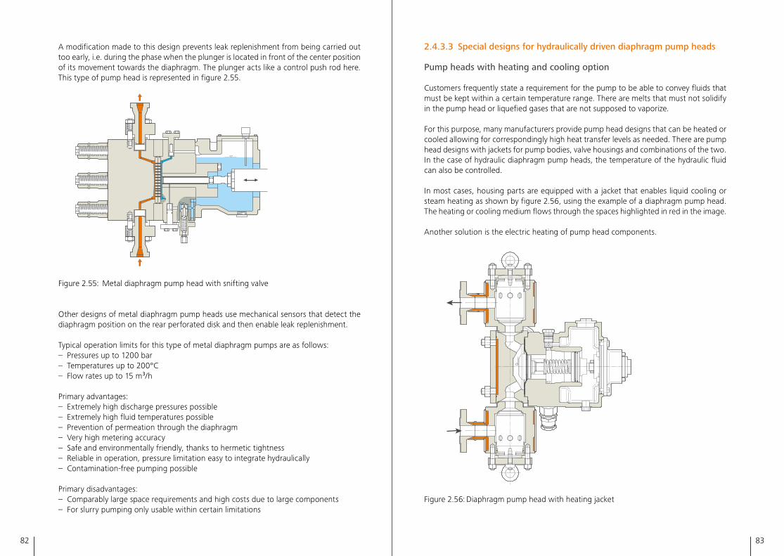
82 83
2.4.3.3 Special designs for hydraulically driven diaphragm pump heads
Pump heads with heating and cooling option
Customers frequently state a requirement for the pump to be able to convey fluids that must be kept within a certain temperature range� There are melts that must not solidify in the pump head or liquefied gases that are not supposed to vaporize�
For this purpose, many manufacturers provide pump head designs that can be heated or cooled allowing for correspondingly high heat transfer levels as needed� There are pump head designs with jackets for pump bodies, valve housings and combinations of the two� In the case of hydraulic diaphragm pump heads, the temperature of the hydraulic fluid can also be controlled�
In most cases, housing parts are equipped with a jacket that enables liquid cooling or steam heating as shown by figure 2�56, using the example of a diaphragm pump head� The heating or cooling medium flows through the spaces highlighted in red in the image� Another solution is the electric heating of pump head components�
2.58
Figure 2�56: Diaphragm pump head with heating jacket
A modification made to this design prevents leak replenishment from being carried out too early, i�e� during the phase when the plunger is located in front of the center position of its movement towards the diaphragm� The plunger acts like a control push rod here� This type of pump head is represented in figure 2�55�
2.46 2.48
2.50 2.53 2.54
2.56 2.67
Figure 2�55: Metal diaphragm pump head with snifting valve
Other designs of metal diaphragm pump heads use mechanical sensors that detect the diaphragm position on the rear perforated disk and then enable leak replenishment�
Typical operation limits for this type of metal diaphragm pumps are as follows:– Pressures up to 1200 bar– Temperatures up to 200°C– Flow rates up to 15 m³/h
Primary advantages:– Extremely high discharge pressures possible– Extremely high fluid temperatures possible– Prevention of permeation through the diaphragm– Very high metering accuracy– Safe and environmentally friendly, thanks to hermetic tightness– Reliable in operation, pressure limitation easy to integrate hydraulically– Contamination-free pumping possible
Primary disadvantages:– Comparably large space requirements and high costs due to large components– For slurry pumping only usable within certain limitations
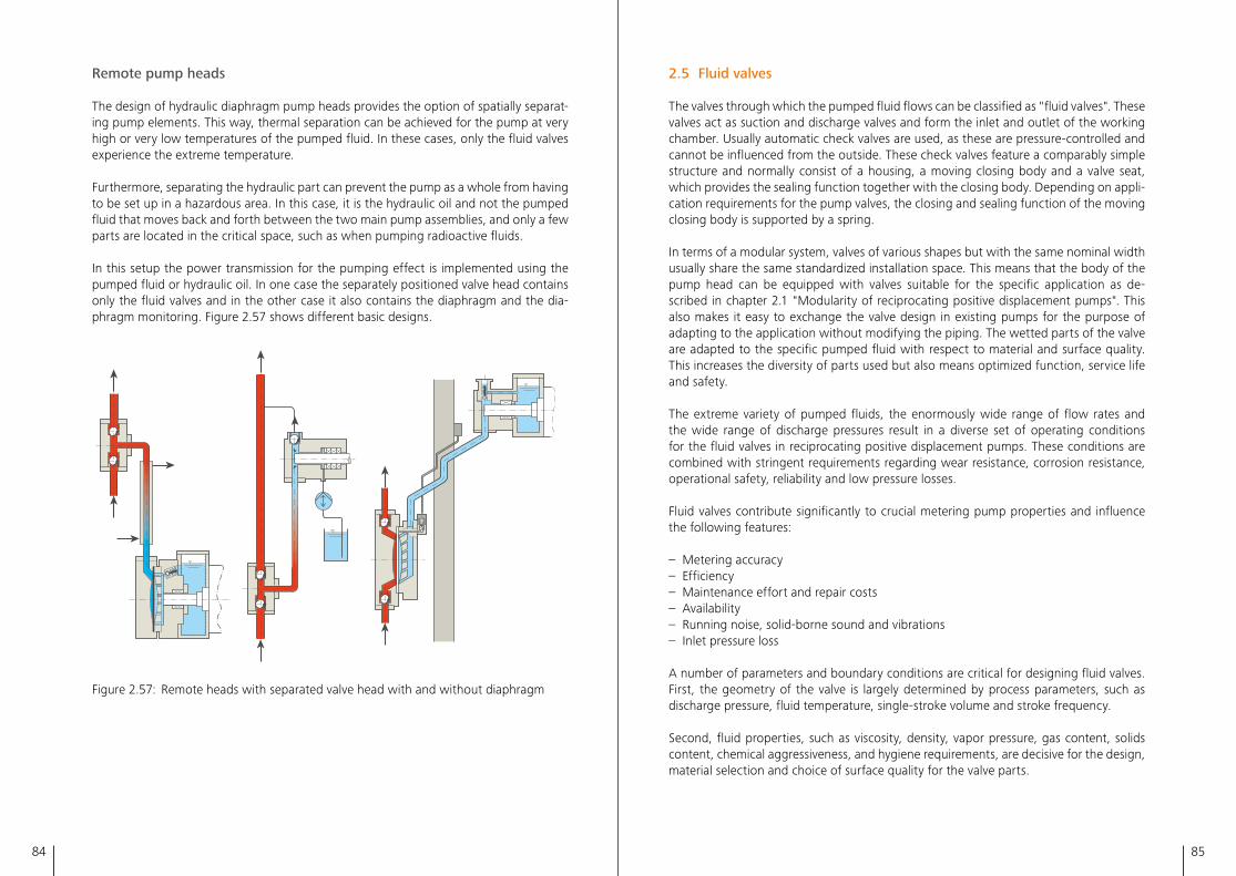
84 85
2.5 Fluid valves
The valves through which the pumped fluid flows can be classified as "fluid valves"� These valves act as suction and discharge valves and form the inlet and outlet of the working chamber� Usually automatic check valves are used, as these are pressure-controlled and cannot be influenced from the outside� These check valves feature a comparably simple structure and normally consist of a housing, a moving closing body and a valve seat, which provides the sealing function together with the closing body� Depending on appli-cation requirements for the pump valves, the closing and sealing function of the moving closing body is supported by a spring�
In terms of a modular system, valves of various shapes but with the same nominal width usually share the same standardized installation space� This means that the body of the pump head can be equipped with valves suitable for the specific application as de-scribed in chapter 2�1 "Modularity of reciprocating positive displacement pumps"� This also makes it easy to exchange the valve design in existing pumps for the purpose of adapting to the application without modifying the piping� The wetted parts of the valve are adapted to the specific pumped fluid with respect to material and surface quality� This increases the diversity of parts used but also means optimized function, service life and safety�
The extreme variety of pumped fluids, the enormously wide range of flow rates and the wide range of discharge pressures result in a diverse set of operating conditions for the fluid valves in reciprocating positive displacement pumps� These conditions are combined with stringent requirements regarding wear resistance, corrosion resistance, operational safety, reliability and low pressure losses�
Fluid valves contribute significantly to crucial metering pump properties and influence the following features:
– Metering accuracy– Efficiency– Maintenance effort and repair costs– Availability– Running noise, solid-borne sound and vibrations– Inlet pressure loss
A number of parameters and boundary conditions are critical for designing fluid valves� First, the geometry of the valve is largely determined by process parameters, such as discharge pressure, fluid temperature, single-stroke volume and stroke frequency�
Second, fluid properties, such as viscosity, density, vapor pressure, gas content, solids content, chemical aggressiveness, and hygiene requirements, are decisive for the design, material selection and choice of surface quality for the valve parts�
Remote pump heads
The design of hydraulic diaphragm pump heads provides the option of spatially separat-ing pump elements� This way, thermal separation can be achieved for the pump at very high or very low temperatures of the pumped fluid� In these cases, only the fluid valves experience the extreme temperature�
Furthermore, separating the hydraulic part can prevent the pump as a whole from having to be set up in a hazardous area� In this case, it is the hydraulic oil and not the pumped fluid that moves back and forth between the two main pump assemblies, and only a few parts are located in the critical space, such as when pumping radioactive fluids�
In this setup the power transmission for the pumping effect is implemented using the pumped fluid or hydraulic oil� In one case the separately positioned valve head contains only the fluid valves and in the other case it also contains the diaphragm and the dia-phragm monitoring� Figure 2�57 shows different basic designs�
2.58
Figure 2�57: Remote heads with separated valve head with and without diaphragm
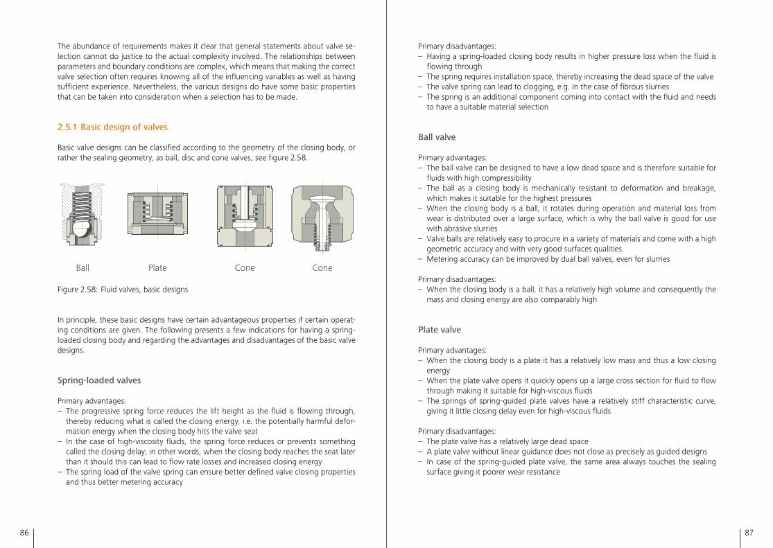
86 87
Primary disadvantages:– Having a spring-loaded closing body results in higher pressure loss when the fluid is
flowing through– The spring requires installation space, thereby increasing the dead space of the valve– The valve spring can lead to clogging, e�g� in the case of fibrous slurries– The spring is an additional component coming into contact with the fluid and needs
to have a suitable material selection
Ball valve
Primary advantages:– The ball valve can be designed to have a low dead space and is therefore suitable for
fluids with high compressibility– The ball as a closing body is mechanically resistant to deformation and breakage,
which makes it suitable for the highest pressures– When the closing body is a ball, it rotates during operation and material loss from
wear is distributed over a large surface, which is why the ball valve is good for use with abrasive slurries
– Valve balls are relatively easy to procure in a variety of materials and come with a high geometric accuracy and with very good surfaces qualities
– Metering accuracy can be improved by dual ball valves, even for slurries
Primary disadvantages:– When the closing body is a ball, it has a relatively high volume and consequently the
mass and closing energy are also comparably high
Plate valve
Primary advantages:– When the closing body is a plate it has a relatively low mass and thus a low closing
energy– When the plate valve opens it quickly opens up a large cross section for fluid to flow
through making it suitable for high-viscous fluids– The springs of spring-guided plate valves have a relatively stiff characteristic curve,
giving it little closing delay even for high-viscous fluids
Primary disadvantages:– The plate valve has a relatively large dead space– A plate valve without linear guidance does not close as precisely as guided designs– In case of the spring-guided plate valve, the same area always touches the sealing
surface giving it poorer wear resistance
The abundance of requirements makes it clear that general statements about valve se-lection cannot do justice to the actual complexity involved� The relationships between parameters and boundary conditions are complex, which means that making the correct valve selection often requires knowing all of the influencing variables as well as having sufficient experience� Nevertheless, the various designs do have some basic properties that can be taken into consideration when a selection has to be made�
2.5.1 Basic design of valves
Basic valve designs can be classified according to the geometry of the closing body, or rather the sealing geometry, as ball, disc and cone valves, see figure 2�58�
ConeConeBall Plate
2.60
Figure 2�58: Fluid valves, basic designs
In principle, these basic designs have certain advantageous properties if certain operat-ing conditions are given� The following presents a few indications for having a spring-loaded closing body and regarding the advantages and disadvantages of the basic valve designs�
Spring-loaded valves
Primary advantages:– The progressive spring force reduces the lift height as the fluid is flowing through,
thereby reducing what is called the closing energy, i�e� the potentially harmful defor-mation energy when the closing body hits the valve seat
– In the case of high-viscosity fluids, the spring force reduces or prevents something called the closing delay; in other words, when the closing body reaches the seat later than it should this can lead to flow rate losses and increased closing energy
– The spring load of the valve spring can ensure better defined valve closing properties and thus better metering accuracy
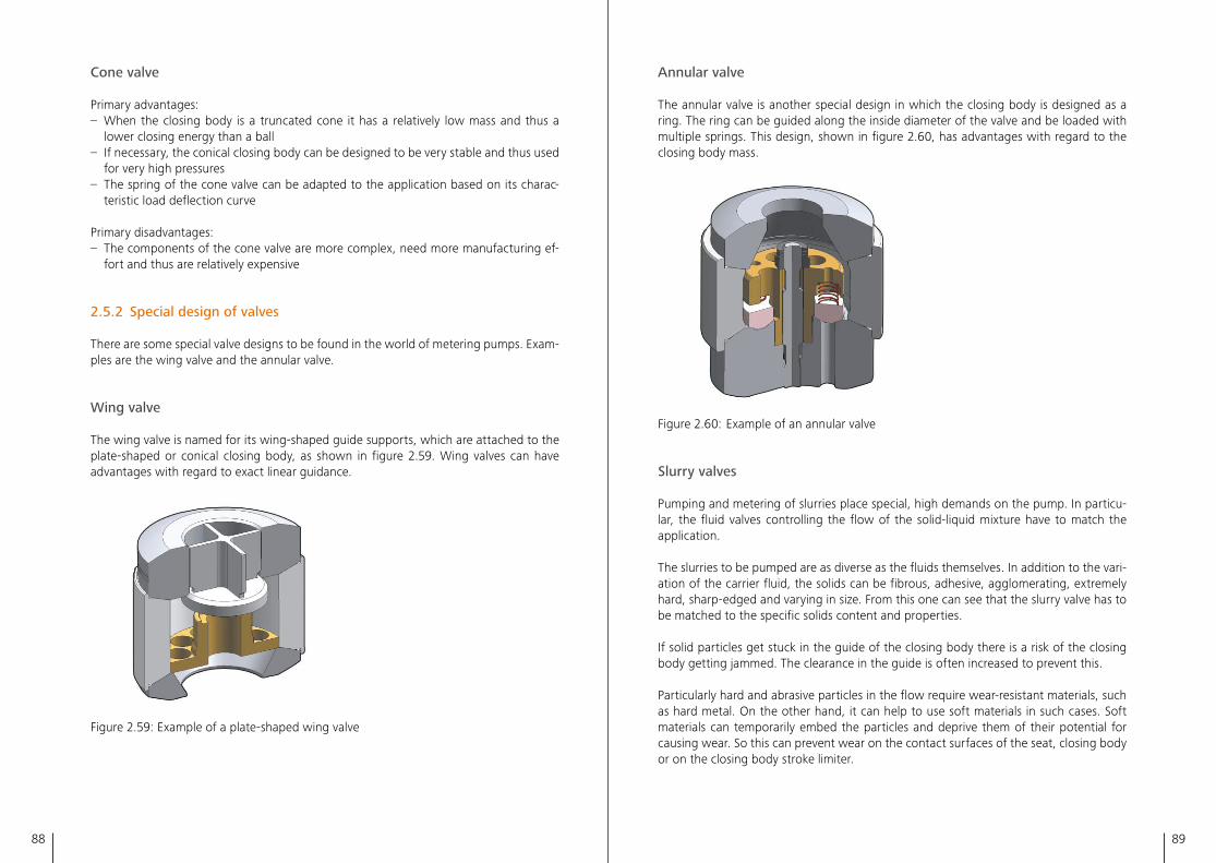
88 89
Annular valve
The annular valve is another special design in which the closing body is designed as a ring� The ring can be guided along the inside diameter of the valve and be loaded with multiple springs� This design, shown in figure 2�60, has advantages with regard to the closing body mass�
Figure 2�60: Example of an annular valve
Slurry valves
Pumping and metering of slurries place special, high demands on the pump� In particu-lar, the fluid valves controlling the flow of the solid-liquid mixture have to match the application�
The slurries to be pumped are as diverse as the fluids themselves� In addition to the vari-ation of the carrier fluid, the solids can be fibrous, adhesive, agglomerating, extremely hard, sharp-edged and varying in size� From this one can see that the slurry valve has to be matched to the specific solids content and properties�
If solid particles get stuck in the guide of the closing body there is a risk of the closing body getting jammed� The clearance in the guide is often increased to prevent this�
Particularly hard and abrasive particles in the flow require wear-resistant materials, such as hard metal� On the other hand, it can help to use soft materials in such cases� Soft materials can temporarily embed the particles and deprive them of their potential for causing wear� So this can prevent wear on the contact surfaces of the seat, closing body or on the closing body stroke limiter�
Cone valve
Primary advantages:– When the closing body is a truncated cone it has a relatively low mass and thus a
lower closing energy than a ball– If necessary, the conical closing body can be designed to be very stable and thus used
for very high pressures– The spring of the cone valve can be adapted to the application based on its charac-
teristic load deflection curve
Primary disadvantages:– The components of the cone valve are more complex, need more manufacturing ef-
fort and thus are relatively expensive
2.5.2 Special design of valves
There are some special valve designs to be found in the world of metering pumps� Exam-ples are the wing valve and the annular valve�
Wing valve
The wing valve is named for its wing-shaped guide supports, which are attached to the plate-shaped or conical closing body, as shown in figure 2�59� Wing valves can have advantages with regard to exact linear guidance�
Figure 2�59: Example of a plate-shaped wing valve
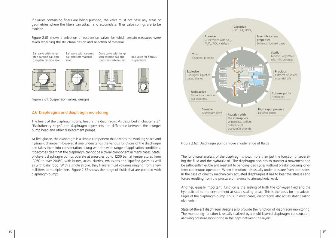
90 91
Corrosive HCL, HF, HNO3
Toxic Chlorine, bromine
Sterile Lecithin, vegetable oils, milk products
Radioactive Plutionium, uranium salt solutions
Extreme purity Antibiotics
Abrasive Suspensions with SiO2, AI2O3, TiO2, catalysts
Poor lubricating properties Solvents, liquified gases
Sensible Aluminium alkyls
High vapor pressure Liquified gases
Reaction with the atmosphere Waterglass, sodium, dichloride of titanium(II) chloride
Precious Extracts of spices, essential oils
Explosive Hydrogen, liquefied gases, silanes
Figure 2�62: Diaphragm pumps move a wide range of fluids
The functional analysis of the diaphragm shows more than just the function of separat-ing the fluid and the hydraulic oil� The diaphragm also has to transfer a movement and be sufficiently flexible and resistant to bending load cycles without breaking during long-term continuous operation� When in motion, it is usually under pressure from both sides� In the case of directly mechanically actuated diaphragms it has to bear the stresses and forces resulting from the pressure difference to atmospheric level�
Another, equally important, function is the sealing of both the conveyed fluid and the hydraulic oil to the environment at static sealing areas� This is the basis for the advan-tages of the diaphragm pump� Thus, in most cases, diaphragms also act as static sealing elements�
State-of-the-art diaphragm designs also provide the function of diaphragm monitoring� The monitoring function is usually realized by a multi-layered diaphragm construction, allowing pressure monitoring in the gaps between the layers�
If slurries containing fibers are being pumped, the valve must not have any areas or geometries where the fibers can attach and accumulate� Thus valve springs are to be avoided�
Figure 2�61 shows a selection of suspension valves for which certain measures were taken regarding the structural design and selection of material:
Ball valve with tung-sten carbide ball and tungsten carbide seat
Ball valve with ceramic ball and soft material seat
Cone valve with tung-sten carbide ball and tungsten carbide seat
Ball valve for fibrous suspensions
Figure 2�61: Suspension valves, designs
2.6 Diaphragms and diaphragm monitoring
The heart of the diaphragm pump head is the diaphragm� As described in chapter 2�3�1 "Evolutionary steps", the diaphragm represents the difference between the plunger pump head and other displacement pumps�
At first glance, the diaphragm is a simple component that divides the working space and hydraulic chamber� However, if one understands the various functions of the diaphragm and takes them into consideration, along with the wide range of application conditions, it becomes clear that the diaphragm cannot be a trivial component in many cases� State-of-the-art diaphragm pumps operate at pressures up to 1200 bar, at temperatures from -30°C to over 200°C, with brines, acids, slurries, emulsions and liquefied gases as well as with baby food� With a single stroke, they transfer fluid volumes ranging from a few milliliters to multiple liters� Figure 2�62 shows the range of fluids that are pumped with diaphragm pumps�
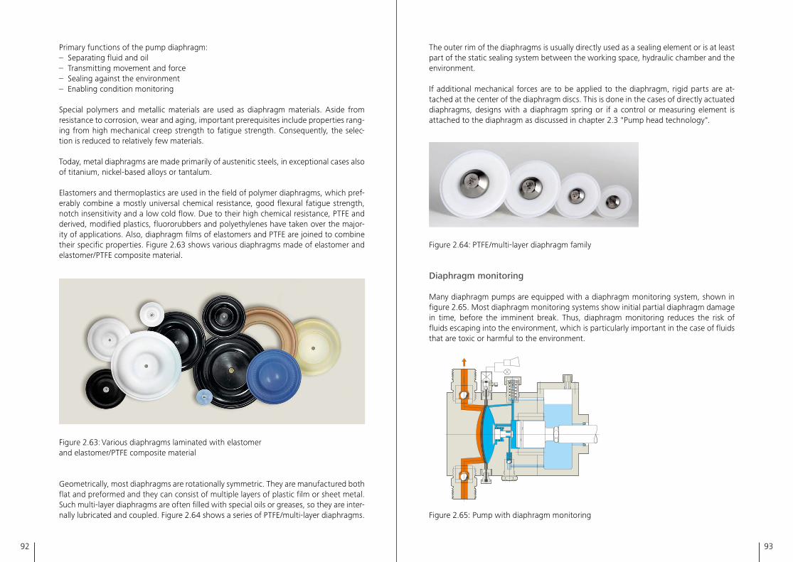
92 93
The outer rim of the diaphragms is usually directly used as a sealing element or is at least part of the static sealing system between the working space, hydraulic chamber and the environment�
If additional mechanical forces are to be applied to the diaphragm, rigid parts are at-tached at the center of the diaphragm discs� This is done in the cases of directly actuated diaphragms, designs with a diaphragm spring or if a control or measuring element is attached to the diaphragm as discussed in chapter 2�3 "Pump head technology"�
Figure 2�64: PTFE/multi-layer diaphragm family
Diaphragm monitoring
Many diaphragm pumps are equipped with a diaphragm monitoring system, shown in figure 2�65� Most diaphragm monitoring systems show initial partial diaphragm damage in time, before the imminent break� Thus, diaphragm monitoring reduces the risk of fluids escaping into the environment, which is particularly important in the case of fluids that are toxic or harmful to the environment�
2.46 2.48
2.50 2.53 2.54
2.56 2.67
Figure 2�65: Pump with diaphragm monitoring
Primary functions of the pump diaphragm:– Separating fluid and oil– Transmitting movement and force– Sealing against the environment– Enabling condition monitoring
Special polymers and metallic materials are used as diaphragm materials� Aside from resistance to corrosion, wear and aging, important prerequisites include properties rang-ing from high mechanical creep strength to fatigue strength� Consequently, the selec-tion is reduced to relatively few materials�
Today, metal diaphragms are made primarily of austenitic steels, in exceptional cases also of titanium, nickel-based alloys or tantalum�
Elastomers and thermoplastics are used in the field of polymer diaphragms, which pref-erably combine a mostly universal chemical resistance, good flexural fatigue strength, notch insensitivity and a low cold flow� Due to their high chemical resistance, PTFE and derived, modified plastics, fluororubbers and polyethylenes have taken over the major-ity of applications� Also, diaphragm films of elastomers and PTFE are joined to combine their specific properties� Figure 2�63 shows various diaphragms made of elastomer and elastomer/PTFE composite material�
Figure 2�63: Various diaphragms laminated with elastomer and elastomer/PTFE composite material
Geometrically, most diaphragms are rotationally symmetric� They are manufactured both flat and preformed and they can consist of multiple layers of plastic film or sheet metal� Such multi-layer diaphragms are often filled with special oils or greases, so they are inter-nally lubricated and coupled� Figure 2�64 shows a series of PTFE/multi-layer diaphragms�
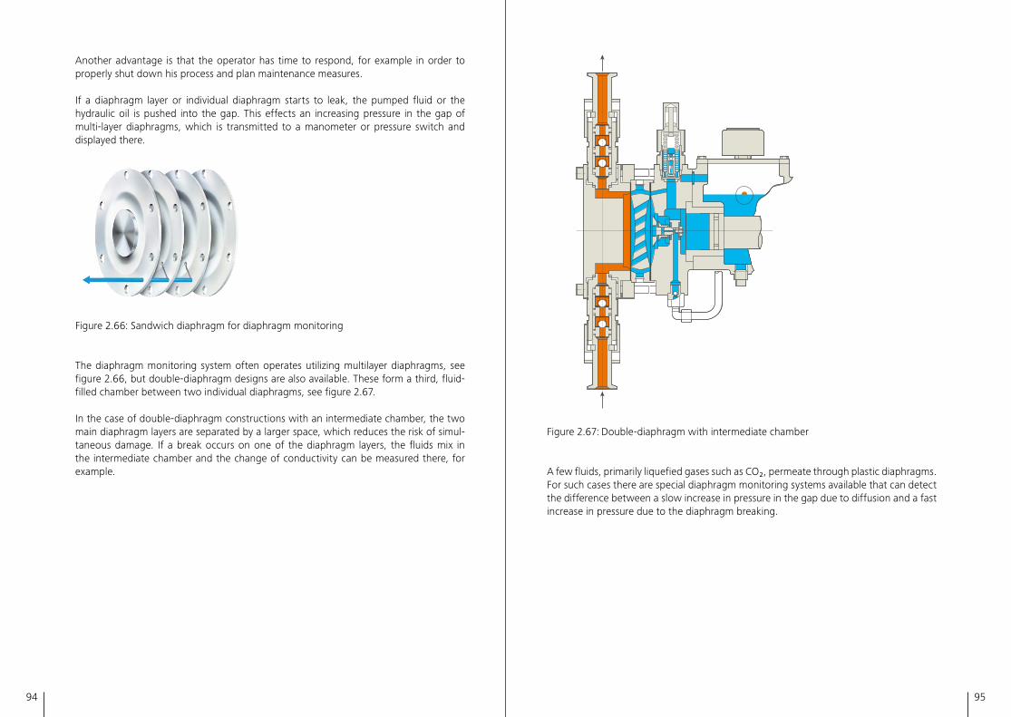
94 95
Figure 2�67: Double-diaphragm with intermediate chamber
A few fluids, primarily liquefied gases such as CO₂, permeate through plastic diaphragms� For such cases there are special diaphragm monitoring systems available that can detect the difference between a slow increase in pressure in the gap due to diffusion and a fast increase in pressure due to the diaphragm breaking�
Another advantage is that the operator has time to respond, for example in order to properly shut down his process and plan maintenance measures�
If a diaphragm layer or individual diaphragm starts to leak, the pumped fluid or the hydraulic oil is pushed into the gap� This effects an increasing pressure in the gap of multi-layer diaphragms, which is transmitted to a manometer or pressure switch and displayed there�
Figure 2�66: Sandwich diaphragm for diaphragm monitoring
The diaphragm monitoring system often operates utilizing multilayer diaphragms, see figure 2�66, but double-diaphragm designs are also available� These form a third, fluid-filled chamber between two individual diaphragms, see figure 2�67�
In the case of double-diaphragm constructions with an intermediate chamber, the two main diaphragm layers are separated by a larger space, which reduces the risk of simul-taneous damage� If a break occurs on one of the diaphragm layers, the fluids mix in the intermediate chamber and the change of conductivity can be measured there, for example�
96 97
3
This chapter summarizes the key directives, specifications and standards from the field of reciprocating positive displacement pumps. Specific standards also have an effect on the engineering design of a product, such as the "NORSOK coating".
3.1 Directives and standards in Europe
The primary purpose of the directives and standards valid within the European Union is to ensure free movement of goods within the EU� Important European directives for pump technology include the "Machinery Directive" and the "ATEX" Explosion Protec-tion Directive�
Compliance with directive 2006/42/EC (Machinery Directive) is mandatory for shipments within the European Economic Area� In Germany, this directive has been transformed into national law with the "Product Safety Act" (Produktsicherheitsgesetz)�
For operation in potentially explosive areas, the directive 2014/34/EU (ATEX Explosion Protection Directive), is implemented in Germany by means of the "Explosion Protection Product Act" (Explosionsschutzprodukteverordnung)�
The compliance with EU directives must be confirmed with an EU Declaration of Con-formity by the manufacturer�
Harmonized European standards are available for a conformity assessment� These in-clude EN ISO 12100, "Safety of machinery – General principles of design – Risk assess-ment and risk reduction" or, applied to a specific product as a general standard and product-specific standards, for example EN 809, "Pumps and pump units for liquids – Common safety requirements"�
3.2 Explosion protection
In many processes and production sites, explosion protection plays a central role, par-ticularly when pumping combustible substances�
Directives, standards, and specifications
Preventing explosions means preventing the simultaneous occurrence of flammable sub-stances such as gas, vapor, mist or dust, the oxygen contained in the air, and a source of ignition at a given location� The general term "source of ignition" includes potential hazards such as sparks, hot temperatures, radiation, lightning strikes, electrostatic charges, etc�
The general purpose is to prevent the formation of a potentially explosive atmosphere (primary explosion protection)� If this is not possible, the objective is to prevent the igni-tion of this explosive atmosphere (secondary explosion protection)� Should this also be impossible, the effect of the explosion must be prevented or minimized (tertiary explo-sion protection)�
On this basis, there are various types of ignition protection (Ex e, Ex i, Ex d, Ex n, Ex p, Ex c, etc�), that can be used for equipment in potentially explosive areas�
In the European Union, equipment intended for use in potentially explosive atmospheres must be designed in accordance with the ATEX directive, i�e� the EU directive 2014/34/EU� This applies to pumps, pump skids, and packages� For plant operators, Directive 1999/92/EC also applies� Corresponding codes are the National Electrical Code (NEC) for the USA and the Canadian Electrical Code (CEC) for Canada�
In terms of standards, the most important series of standards is DIN EN 60079 for elec-trical equipment and DIN EN 80079 for non-electrical equipment� These are based on the international standards IEC 60079 and IEC 80079� To date, these common standards have been introduced on an international level� These have extended to common regula-tions that form the IECEx Community� Unfortunately, different country-specific laws are in place around the world� IECEx is currently only applied in a few countries, despite the fact that many countries are represented in the IEC organization� For example, manufac-turers of equipment that is installed in potentially explosive atmospheres must comply with the laws and regulations of the respective country of installation or, if there is no country-specific law in place, to the requirements of the operator�
In addition to the classification of the type of explosive atmosphere (mining, gas, dust, USA: fibers), the operator determines the explosion protection zone (Zone 0, 1, 2; USA: NEC 500: division 1 or 2) and thus the protection level necessary for the equipment to be installed in the explosive atmosphere� In addition, for gases, the operator defines the gas group and the temperature class, corresponding to the explosion hazard of the gas and the maximum permitted surface temperature of the gas� As a result, no self-ignition is possible�
For equipment manufacturers, this requires having employees who are familiar with the field of explosion protection, who select the right equipment for the respective applica-tion and finally install and connect it correctly�
One option for certifying the necessary qualification in accordance with the IEC stand-ards is the IECEx scheme of "IECEx Certified Persons"�
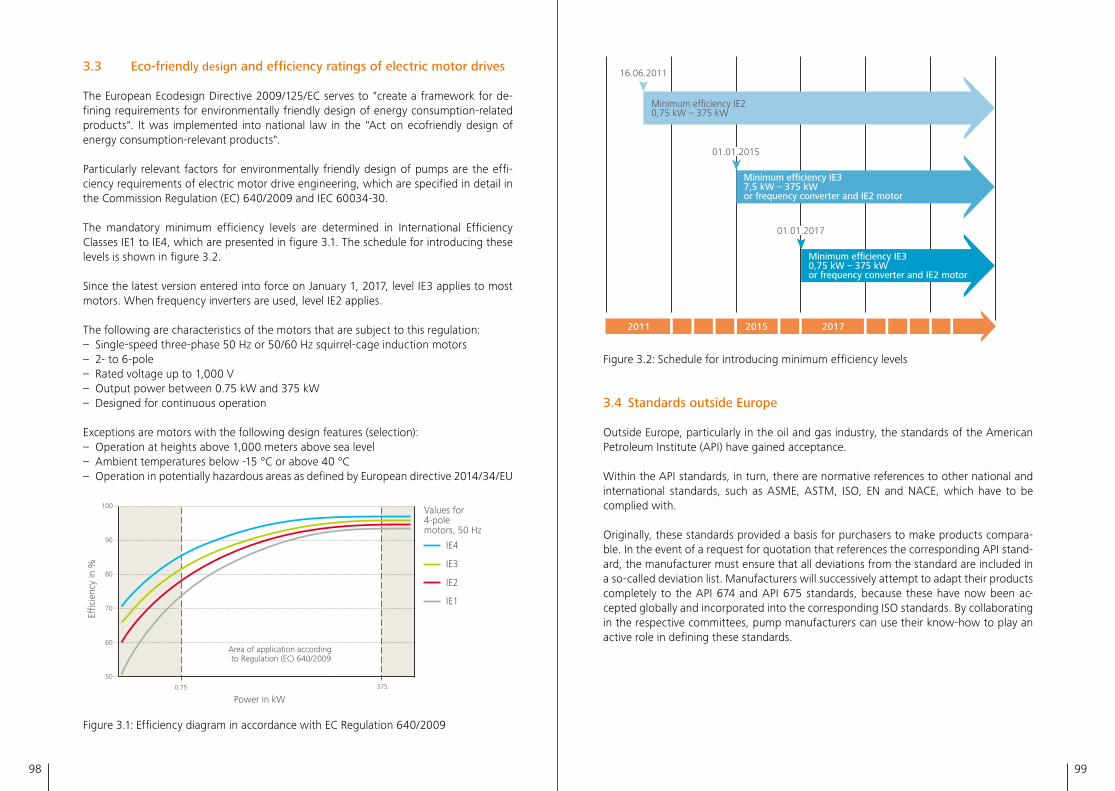
98 99
3.3 Eco-friendly design and efficiency ratings of electric motor drives
The European Ecodesign Directive 2009/125/EC serves to "create a framework for de-fining requirements for environmentally friendly design of energy consumption-related products"� It was implemented into national law in the "Act on ecofriendly design of energy consumption-relevant products"�
Particularly relevant factors for environmentally friendly design of pumps are the effi-ciency requirements of electric motor drive engineering, which are specified in detail in the Commission Regulation (EC) 640/2009 and IEC 60034-30�
The mandatory minimum efficiency levels are determined in International Efficiency Classes IE1 to IE4, which are presented in figure 3�1� The schedule for introducing these levels is shown in figure 3�2�
Since the latest version entered into force on January 1, 2017, level IE3 applies to most motors� When frequency inverters are used, level IE2 applies�
The following are characteristics of the motors that are subject to this regulation:– Single-speed three-phase 50 Hz or 50/60 Hz squirrel-cage induction motors– 2- to 6-pole– Rated voltage up to 1,000 V– Output power between 0�75 kW and 375 kW– Designed for continuous operation
Exceptions are motors with the following design features (selection):– Operation at heights above 1,000 meters above sea level– Ambient temperatures below -15 °C or above 40 °C– Operation in potentially hazardous areas as defined by European directive 2014/34/EU
Power in kW
IE4
IE3
IE2
IE1
Area of application according to Regulation (EC) 640/2009
E�ci
ency
in %
0,75 375
100
90
80
70
60
50
Values for 4-pole motors, 50 Hz
Figure 3�1: Efficiency diagram in accordance with EC Regulation 640/2009
16.06.2011
01.01.2015
01.01.2017
2011 2015 2017
Minimum e�ciency IE30,75 kW – 375 kWor frequency converter and IE2 motor
Minimum e�ciency IE37,5 kW – 375 kWor frequency converter and IE2 motor
Minimum efficiency IE20,75 kW – 375 kW
Figure 3�2: Schedule for introducing minimum efficiency levels
3.4 Standards outside Europe
Outside Europe, particularly in the oil and gas industry, the standards of the American Petroleum Institute (API) have gained acceptance�
Within the API standards, in turn, there are normative references to other national and international standards, such as ASME, ASTM, ISO, EN and NACE, which have to be complied with�
Originally, these standards provided a basis for purchasers to make products compara-ble� In the event of a request for quotation that references the corresponding API stand-ard, the manufacturer must ensure that all deviations from the standard are included in a so-called deviation list� Manufacturers will successively attempt to adapt their products completely to the API 674 and API 675 standards, because these have now been ac-cepted globally and incorporated into the corresponding ISO standards� By collaborating in the respective committees, pump manufacturers can use their know-how to play an active role in defining these standards�
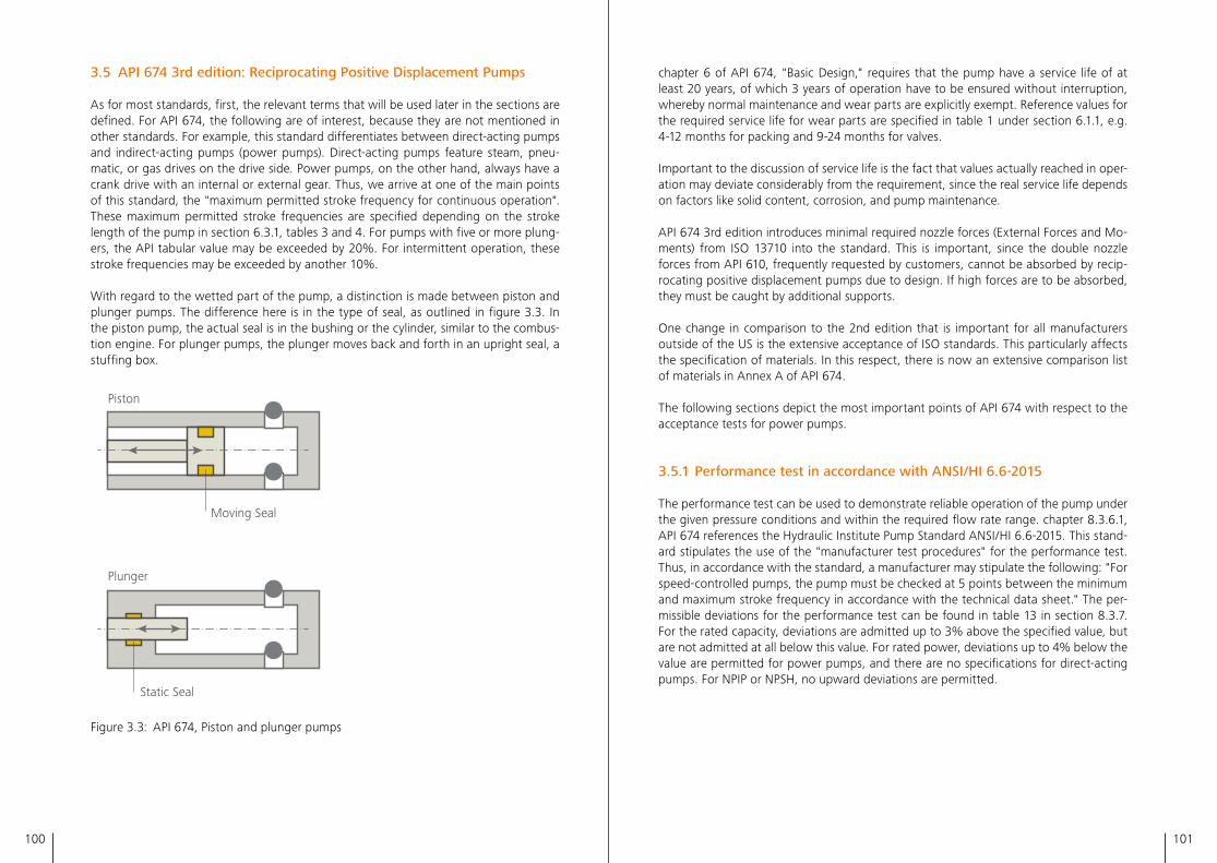
100 101
3.5 API 674 3rd edition: Reciprocating Positive Displacement Pumps
As for most standards, first, the relevant terms that will be used later in the sections are defined� For API 674, the following are of interest, because they are not mentioned in other standards� For example, this standard differentiates between direct-acting pumps and indirect-acting pumps (power pumps)� Direct-acting pumps feature steam, pneu-matic, or gas drives on the drive side� Power pumps, on the other hand, always have a crank drive with an internal or external gear� Thus, we arrive at one of the main points of this standard, the "maximum permitted stroke frequency for continuous operation"� These maximum permitted stroke frequencies are specified depending on the stroke length of the pump in section 6�3�1, tables 3 and 4� For pumps with five or more plung-ers, the API tabular value may be exceeded by 20%� For intermittent operation, these stroke frequencies may be exceeded by another 10%�
With regard to the wetted part of the pump, a distinction is made between piston and plunger pumps� The difference here is in the type of seal, as outlined in figure 3�3� In the piston pump, the actual seal is in the bushing or the cylinder, similar to the combus-tion engine� For plunger pumps, the plunger moves back and forth in an upright seal, a stuffing box�
Piston
Moving Seal
Static Seal
Plunger
Figure 3�3: API 674, Piston and plunger pumps
chapter 6 of API 674, "Basic Design," requires that the pump have a service life of at least 20 years, of which 3 years of operation have to be ensured without interruption, whereby normal maintenance and wear parts are explicitly exempt� Reference values for the required service life for wear parts are specified in table 1 under section 6�1�1, e�g� 4-12 months for packing and 9-24 months for valves�
Important to the discussion of service life is the fact that values actually reached in oper-ation may deviate considerably from the requirement, since the real service life depends on factors like solid content, corrosion, and pump maintenance�
API 674 3rd edition introduces minimal required nozzle forces (External Forces and Mo-ments) from ISO 13710 into the standard� This is important, since the double nozzle forces from API 610, frequently requested by customers, cannot be absorbed by recip-rocating positive displacement pumps due to design� If high forces are to be absorbed, they must be caught by additional supports�
One change in comparison to the 2nd edition that is important for all manufacturers outside of the US is the extensive acceptance of ISO standards� This particularly affects the specification of materials� In this respect, there is now an extensive comparison list of materials in Annex A of API 674�
The following sections depict the most important points of API 674 with respect to the acceptance tests for power pumps�
3.5.1 Performance test in accordance with ANSI/HI 6.6-2015
The performance test can be used to demonstrate reliable operation of the pump under the given pressure conditions and within the required flow rate range� chapter 8�3�6�1, API 674 references the Hydraulic Institute Pump Standard ANSI/HI 6�6-2015� This stand-ard stipulates the use of the "manufacturer test procedures" for the performance test� Thus, in accordance with the standard, a manufacturer may stipulate the following: "For speed-controlled pumps, the pump must be checked at 5 points between the minimum and maximum stroke frequency in accordance with the technical data sheet�" The per-missible deviations for the performance test can be found in table 13 in section 8�3�7� For the rated capacity, deviations are admitted up to 3% above the specified value, but are not admitted at all below this value� For rated power, deviations up to 4% below the value are permitted for power pumps, and there are no specifications for direct-acting pumps� For NPIP or NPSH, no upward deviations are permitted�
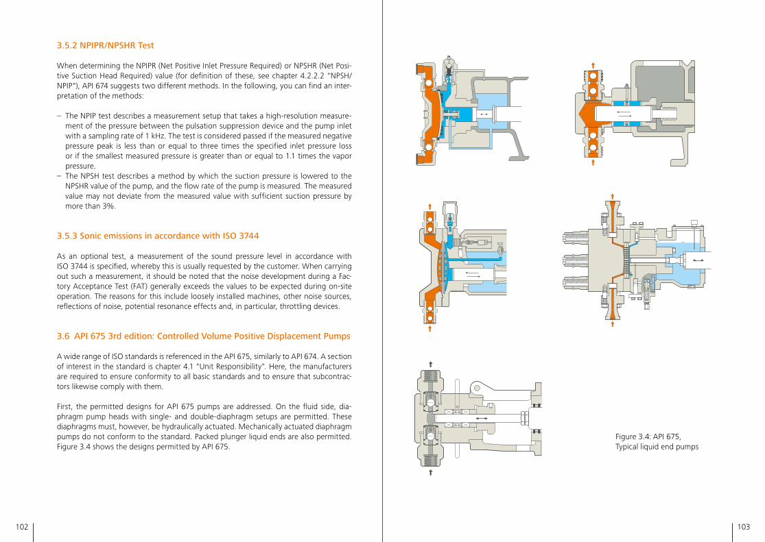
102 103
3.5.2 NPIPR/NPSHR Test
When determining the NPIPR (Net Positive Inlet Pressure Required) or NPSHR (Net Posi-tive Suction Head Required) value (for definition of these, see chapter 4�2�2�2 "NPSH/ NPIP"), API 674 suggests two different methods� In the following, you can find an inter-pretation of the methods:
– The NPIP test describes a measurement setup that takes a high-resolution measure-ment of the pressure between the pulsation suppression device and the pump inlet with a sampling rate of 1 kHz� The test is considered passed if the measured negative pressure peak is less than or equal to three times the specified inlet pressure loss or if the smallest measured pressure is greater than or equal to 1�1 times the vapor pressure�
– The NPSH test describes a method by which the suction pressure is lowered to the NPSHR value of the pump, and the flow rate of the pump is measured� The measured value may not deviate from the measured value with sufficient suction pressure by more than 3%�
3.5.3 Sonic emissions in accordance with ISO 3744
As an optional test, a measurement of the sound pressure level in accordance with ISO 3744 is specified, whereby this is usually requested by the customer� When carrying out such a measurement, it should be noted that the noise development during a Fac-tory Acceptance Test (FAT) generally exceeds the values to be expected during on-site operation� The reasons for this include loosely installed machines, other noise sources, reflections of noise, potential resonance effects and, in particular, throttling devices�
3.6 API 675 3rd edition: Controlled Volume Positive Displacement Pumps
A wide range of ISO standards is referenced in the API 675, similarly to API 674� A section of interest in the standard is chapter 4�1 "Unit Responsibility"� Here, the manufacturers are required to ensure conformity to all basic standards and to ensure that subcontrac-tors likewise comply with them�
First, the permitted designs for API 675 pumps are addressed� On the fluid side, dia-phragm pump heads with single- and double-diaphragm setups are permitted� These diaphragms must, however, be hydraulically actuated� Mechanically actuated diaphragm pumps do not conform to the standard� Packed plunger liquid ends are also permitted� Figure 3�4 shows the designs permitted by API 675�
Figure 3�4: API 675, Typical liquid end pumps
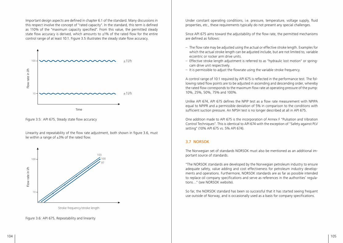
104 105
Important design aspects are defined in chapter 6�1 of the standard� Many discussions in this respect involve the concept of "rated capacity"� In the standard, this term is defined as 110% of the "maximum capacity specified"� From this value, the permitted steady state flow accuracy is derived, which amounts to ±1% of the rated flow for the entire control range of at least 10:1� Figure 3�5 illustrates the steady state flow accuracy�
±1l/h
±1l/h
100
10
Time
Flow
rate
in l/
h
Time
Flow
rate
in l/
h
Figure 3�5: API 675, Steady state flow accuracy
Linearity and repeatability of the flow rate adjustment, both shown in figure 3�6, must lie within a range of ±3% of the rated flow�
100 100103
97
10
Stroke frequency / stroke length
Flow
rate
in l/
hFl
ow ra
te in
l/h
Figure 3�6: API 675, Repeatability and linearity
Under constant operating conditions, i�e� pressure, temperature, voltage supply, fluid properties, etc�, these requirements typically do not present any special challenges�
Since API 675 aims toward the adjustability of the flow rate, the permitted mechanisms are defined as follows:
– The flow rate may be adjusted using the actual or effective stroke length� Examples for which the actual stroke length can be adjusted include, but are not limited to, variable eccentric or rocker arm drive units�
– Effective stroke length adjustment is referred to as "hydraulic lost motion" or spring-cam drive unit respectively�
– It is permissible to adjust the flowrate using the variable stroke frequency�
A control range of 10:1 required by API 675 is reflected in the performance test� The fol-lowing rated flow points are to be adjusted in ascending and descending order, whereby the rated flow corresponds to the maximum flow rate at operating pressure of the pump: 10%, 25%, 50%, 75% and 100%�
Unlike API 674, API 675 defines the NPIP test as a flow rate measurement with NPIPA equal to NPIPR and a permissible deviation of 5% in comparison to the conditions with sufficient suction pressure� An NPSH test is no longer described at all in API 675�
One addition made to API 675 is the incorporation of Annex F "Pulsation and Vibration Control Techniques"� This is identical to API 674 with the exception of "Safety against PLV setting" (10% API 675 vs� 5% API 674)�
3.7 NORSOK
The Norwegian set of standards NORSOK must also be mentioned as an additional im-portant source of standards�
"The NORSOK standards are developed by the Norwegian petroleum industry to ensure adequate safety, value adding and cost effectiveness for petroleum industry develop-ments and operations� Furthermore, NORSOK standards are as far as possible intended to replace oil company specifications and serve as references in the authorities’ regula-tions…" (see NORSOK website)�
So far, the NORSOK standard has been so successful that it has started seeing frequent use outside of Norway, and is occasionally used as a basis for company specifications�
106 107
Corrosion protection NORSOK M-501
NORSOK standards have become established primarily in the area of corrosion protec-tion and material technology� Because corrosion protection currently accounts for a large proportion of maintenance costs, NORSOK M-501 "Surface preparation and protective coating" has very stringent requirements in this respect� Special paint systems require pre-qualification by a paint manufacturer, and the processor must be able to provide the corresponding evidence and have qualifications for painters and paint inspectors�
Special steels NORSOK M-650, NORSOK M-630
NORSOK has very high quality requirements for special steels such as Duplex, Super Duplex, and 6Mo, and manufacturer qualification is mandatory� Because the NORSOK standards in this area have practically become industry standards, the availability of ma-terials with a corresponding qualification is usually not an issue today�
NORSOK standards in the area of material qualification: – NORSOK M-650: "Qualification of manufacturers of special materials" – NORSOK M-630: "Material data sheets and element data sheets for piping"
3.8 NACE
The National Association of Corrosion Engineers (NACE) is a leader in corrosion protec-tion� In particular, the two following sets of standards are used very frequently, primarily in the oil and gas industry, for what is called "acid gas application," i�e� the presence of hydrogen sulfide (H₂S) in the fluid conveyed:– NACE MR0175/ISO 15156: "Petroleum, petrochemical, and natural gas industries –
Materials for use in H₂S-containing environments in oil and gas production"– NACE MR0103: "Petroleum, petrochemical and natural gas industries – Metallic mate-
rials resistant to sulfide stress cracking in corrosive petroleum refining environments" The sets of NACE standards mentioned above specify recommendations for how mate-rial damage induced by acid gas can be prevented�
The standard material 316/316L, corresponding to 1�4401/1�4404, meets the require-ments of both standards, for example� Depending on the H₂S content, temperature, and pH value of the conveyed fluid, it may also be necessary to use high-quality materials (e�g� nickel-based materials)�
3.9 Company and project specifications
Predominantly in the oil and gas industry, but also in other industries, there are addition-al company or project specifications that must be considered� Major corporations such as BASF, Shell, BP, Total, and Saudi Aramco have their own specifications and company standards that pump manufacturers acting as suppliers must meet�
The specifications relate to the pump itself, but also to materials, drives, painting, tests, documentation, etc�
These company specifications are very frequently based on API standards� In the area of paint and materials, they are often based on NORSOK standards�
Project specifications are mostly based on company specifications that are given project-specific, detailed adjustments�
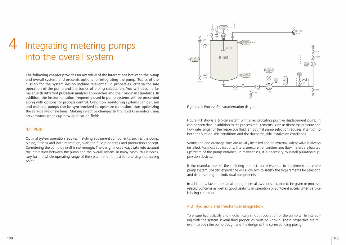
108 109
4
The following chapter provides an overview of the interactions between the pump and overall system, and presents options for integrating the pump. Topics of dis-cussion for the system design include relevant fluid properties, criteria for safe operation of the pump and the basics of piping calculation. You will become fa-miliar with different pulsation analysis approaches and their origin in standards. In addition, the instrumentation frequently used in pump systems will be presented along with options for process control. Condition monitoring systems can be used and multiple pumps can be synchronized to optimize operation, thus optimizing the service life of systems. Making selective changes to the fluid kinematics using servomotors opens up new application fields.
4.1 P&ID
Optimal system operation requires matching equipment components, such as the pump, piping, fittings and instrumentation, with the fluid properties and production concept� Considering the pump by itself is not enough� The design must always take into account the interaction between the pump and the overall system� In many cases, this is neces-sary for the whole operating range of the system and not just for one single operating point�
Integrating metering pumps into the overall system
EUXXX
LSALLXXX
LSAHHXXX
LISXXX
FICXXX
PIT100
PI100
LSAHH100
EU100
LSALL100
EU100
V-101
PSV-10016 bar
V-102
V-105
P-100V-106
V-104
V-103
V-108
V-107
V-112
Vent
V-110
V-109
AG-100
B-100
V-111
CV-100
PIT100
PIT100
FIC100
LIS100
M
M
Valve
Strainer
Diaphragm pump
Drive
Pulsation damper
Agitator
Check valve
Safety valve
Frequency inverter
Level switch
Level switch
Level indicator
Flow meter
Pressure gauges
Pressure transmitter
Container
Arrow for input and output
Figure 4�1: Process & instrumentation diagram
Figure 4�1 shows a typical system with a reciprocating positive displacement pump� It can be seen that, in addition to the process requirements, such as discharge pressure and flow rate range for the respective fluid, an optimal pump selection requires attention to both the suction-side conditions and the discharge-side installation conditions�
Ventilation and drainage lines are usually installed and an external safety valve is always installed� For most applications, filters, pressure transmitters and flow meters are located upstream of the pump entrance� In many cases, it is necessary to install pulsation sup-pression devices�
If the manufacturer of the metering pump is commissioned to implement the entire pump system, specific experience will allow him to satisfy the requirements for selecting and dimensioning the individual components�
In addition, a favorable spatial arrangement allows consideration to be given to process-related concerns as well as good usability in operation or sufficient access when service is being carried out�
4.2 Hydraulic and mechanical integration
To ensure hydraulically and mechanically smooth operation of the pump while interact-ing with the system several fluid properties must be known� These properties are rel-evant to both the pump design and the design of the corresponding piping�
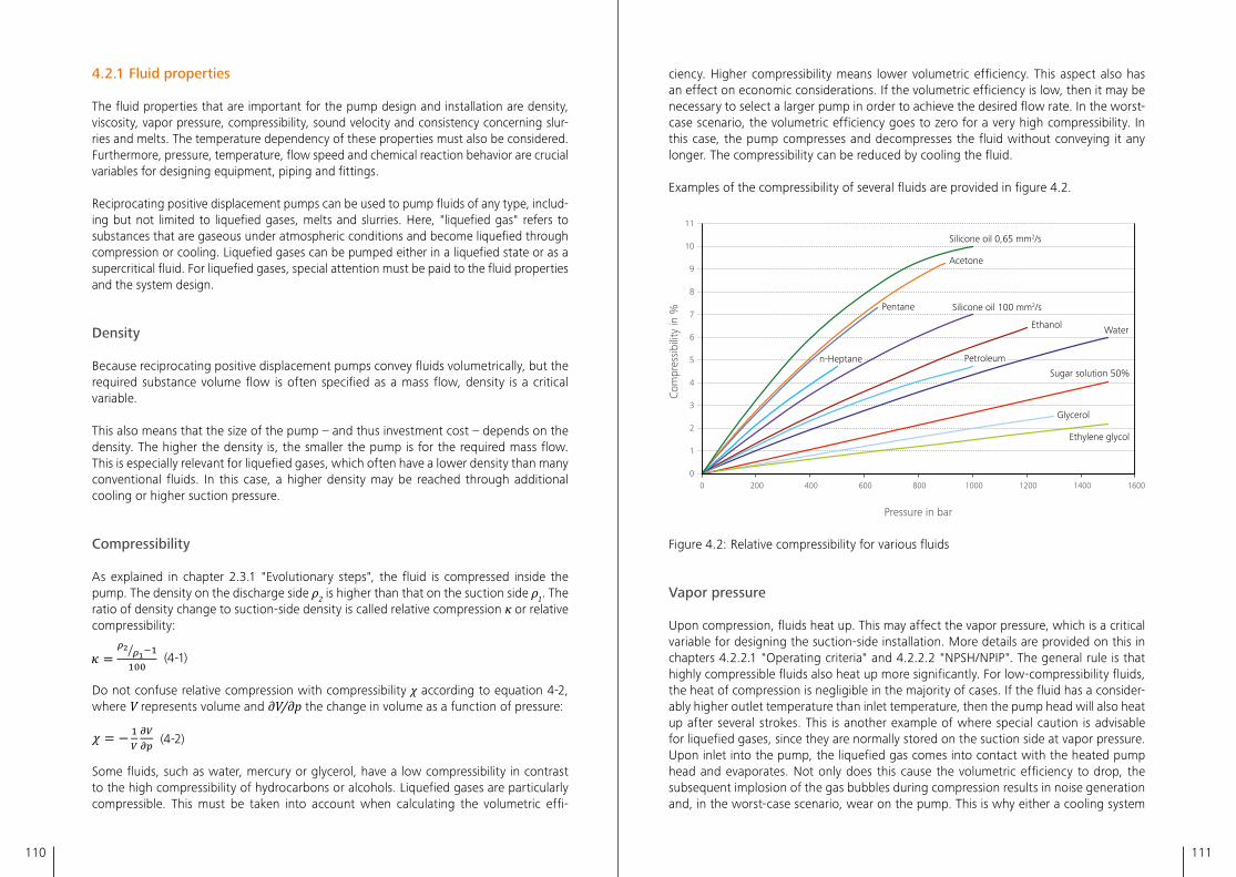
110 111
4.2.1 Fluid properties
The fluid properties that are important for the pump design and installation are density, viscosity, vapor pressure, compressibility, sound velocity and consistency concerning slur-ries and melts� The temperature dependency of these properties must also be considered� Furthermore, pressure, temperature, flow speed and chemical reaction behavior are crucial variables for designing equipment, piping and fittings�
Reciprocating positive displacement pumps can be used to pump fluids of any type, includ-ing but not limited to liquefied gases, melts and slurries� Here, "liquefied gas" refers to substances that are gaseous under atmospheric conditions and become liquefied through compression or cooling� Liquefied gases can be pumped either in a liquefied state or as a supercritical fluid� For liquefied gases, special attention must be paid to the fluid properties and the system design�
Density
Because reciprocating positive displacement pumps convey fluids volumetrically, but the required substance volume flow is often specified as a mass flow, density is a critical variable�
This also means that the size of the pump – and thus investment cost – depends on the density� The higher the density is, the smaller the pump is for the required mass flow� This is especially relevant for liquefied gases, which often have a lower density than many conventional fluids� In this case, a higher density may be reached through additional cooling or higher suction pressure�
Compressibility
As explained in chapter 2�3�1 "Evolutionary steps", the fluid is compressed inside the pump� The density on the discharge side ρ2 is higher than that on the suction side ρ1� The ratio of density change to suction-side density is called relative compression κ or relative compressibility:
(4-1)
Do not confuse relative compression with compressibility χ according to equation 4-2, where V represents volume and ∂V/∂p the change in volume as a function of pressure:
(4-2)
Some fluids, such as water, mercury or glycerol, have a low compressibility in contrast to the high compressibility of hydrocarbons or alcohols� Liquefied gases are particularly compressible� This must be taken into account when calculating the volumetric effi-
ciency� Higher compressibility means lower volumetric efficiency� This aspect also has an effect on economic considerations� If the volumetric efficiency is low, then it may be necessary to select a larger pump in order to achieve the desired flow rate� In the worst-case scenario, the volumetric efficiency goes to zero for a very high compressibility� In this case, the pump compresses and decompresses the fluid without conveying it any longer� The compressibility can be reduced by cooling the fluid�
Examples of the compressibility of several fluids are provided in figure 4�2�
0
1
2
3
4
5
6
7
8
9
10
11
0 200 400 600 800 1000 1200 1400 1600
Glycerol
Sugar solution 50%
Water
Ethylene glycol
Petroleum
Ethanol
Silicone oil 100 mm2/s
n-Heptane
Pentane
Acetone
Silicone oil 0,65 mm2/s
Com
pres
sibi
lity
in %
Pressure in bar
Figure 4�2: Relative compressibility for various fluids
Vapor pressure
Upon compression, fluids heat up� This may affect the vapor pressure, which is a critical variable for designing the suction-side installation� More details are provided on this in chapters 4�2�2�1 "Operating criteria" and 4�2�2�2 "NPSH/NPIP"� The general rule is that highly compressible fluids also heat up more significantly� For low-compressibility fluids, the heat of compression is negligible in the majority of cases� If the fluid has a consider-ably higher outlet temperature than inlet temperature, then the pump head will also heat up after several strokes� This is another example of where special caution is advisable for liquefied gases, since they are normally stored on the suction side at vapor pressure� Upon inlet into the pump, the liquefied gas comes into contact with the heated pump head and evaporates� Not only does this cause the volumetric efficiency to drop, the subsequent implosion of the gas bubbles during compression results in noise generation and, in the worst-case scenario, wear on the pump� This is why either a cooling system
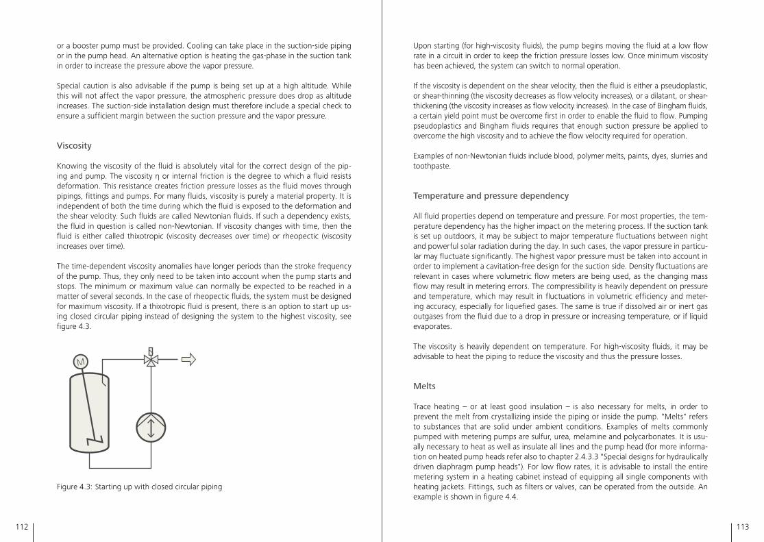
112 113
or a booster pump must be provided� Cooling can take place in the suction-side piping or in the pump head� An alternative option is heating the gas-phase in the suction tank in order to increase the pressure above the vapor pressure�
Special caution is also advisable if the pump is being set up at a high altitude� While this will not affect the vapor pressure, the atmospheric pressure does drop as altitude increases� The suction-side installation design must therefore include a special check to ensure a sufficient margin between the suction pressure and the vapor pressure�
Viscosity
Knowing the viscosity of the fluid is absolutely vital for the correct design of the pip-ing and pump� The viscosity η or internal friction is the degree to which a fluid resists deformation� This resistance creates friction pressure losses as the fluid moves through pipings, fittings and pumps� For many fluids, viscosity is purely a material property� It is independent of both the time during which the fluid is exposed to the deformation and the shear velocity� Such fluids are called Newtonian fluids� If such a dependency exists, the fluid in question is called non-Newtonian� If viscosity changes with time, then the fluid is either called thixotropic (viscosity decreases over time) or rheopectic (viscosity increases over time)�
The time-dependent viscosity anomalies have longer periods than the stroke frequency of the pump� Thus, they only need to be taken into account when the pump starts and stops� The minimum or maximum value can normally be expected to be reached in a matter of several seconds� In the case of rheopectic fluids, the system must be designed for maximum viscosity� If a thixotropic fluid is present, there is an option to start up us-ing closed circular piping instead of designing the system to the highest viscosity, see figure 4�3�
Figure 4�3: Starting up with closed circular piping
Upon starting (for high-viscosity fluids), the pump begins moving the fluid at a low flow rate in a circuit in order to keep the friction pressure losses low� Once minimum viscosity has been achieved, the system can switch to normal operation�
If the viscosity is dependent on the shear velocity, then the fluid is either a pseudoplastic, or shear-thinning (the viscosity decreases as flow velocity increases), or a dilatant, or shear-thickening (the viscosity increases as flow velocity increases)� In the case of Bingham fluids, a certain yield point must be overcome first in order to enable the fluid to flow� Pumping pseudoplastics and Bingham fluids requires that enough suction pressure be applied to overcome the high viscosity and to achieve the flow velocity required for operation�
Examples of non-Newtonian fluids include blood, polymer melts, paints, dyes, slurries and toothpaste�
Temperature and pressure dependency
All fluid properties depend on temperature and pressure� For most properties, the tem-perature dependency has the higher impact on the metering process� If the suction tank is set up outdoors, it may be subject to major temperature fluctuations between night and powerful solar radiation during the day� In such cases, the vapor pressure in particu-lar may fluctuate significantly� The highest vapor pressure must be taken into account in order to implement a cavitation-free design for the suction side� Density fluctuations are relevant in cases where volumetric flow meters are being used, as the changing mass flow may result in metering errors� The compressibility is heavily dependent on pressure and temperature, which may result in fluctuations in volumetric efficiency and meter-ing accuracy, especially for liquefied gases� The same is true if dissolved air or inert gas outgases from the fluid due to a drop in pressure or increasing temperature, or if liquid evaporates�
The viscosity is heavily dependent on temperature� For high-viscosity fluids, it may be advisable to heat the piping to reduce the viscosity and thus the pressure losses�
Melts
Trace heating – or at least good insulation – is also necessary for melts, in order to prevent the melt from crystallizing inside the piping or inside the pump� "Melts" refers to substances that are solid under ambient conditions� Examples of melts commonly pumped with metering pumps are sulfur, urea, melamine and polycarbonates� It is usu-ally necessary to heat as well as insulate all lines and the pump head (for more informa-tion on heated pump heads refer also to chapter 2�4�3�3 "Special designs for hydraulically driven diaphragm pump heads")� For low flow rates, it is advisable to install the entire metering system in a heating cabinet instead of equipping all single components with heating jackets� Fittings, such as filters or valves, can be operated from the outside� An example is shown in figure 4�4�
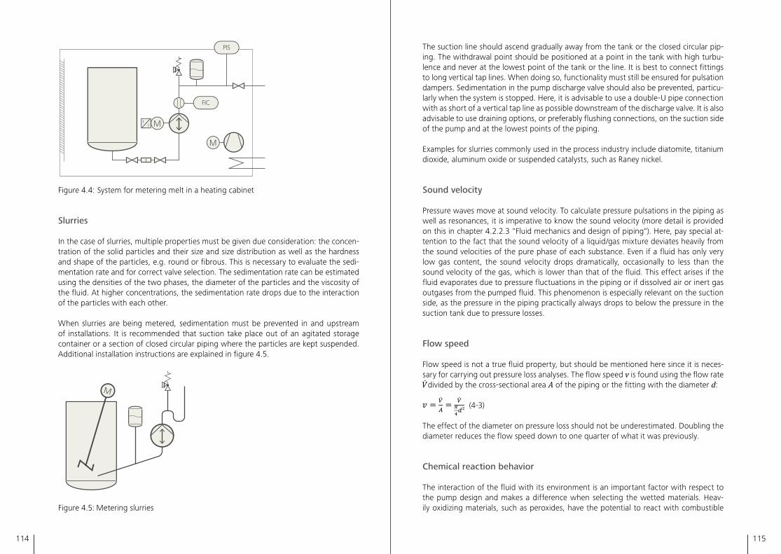
114 115
M
M
ff
PIS
FIC
Figure 4�4: System for metering melt in a heating cabinet
Slurries
In the case of slurries, multiple properties must be given due consideration: the concen-tration of the solid particles and their size and size distribution as well as the hardness and shape of the particles, e�g� round or fibrous� This is necessary to evaluate the sedi-mentation rate and for correct valve selection� The sedimentation rate can be estimated using the densities of the two phases, the diameter of the particles and the viscosity of the fluid� At higher concentrations, the sedimentation rate drops due to the interaction of the particles with each other�
When slurries are being metered, sedimentation must be prevented in and upstream of installations� It is recommended that suction take place out of an agitated storage container or a section of closed circular piping where the particles are kept suspended� Additional installation instructions are explained in figure 4�5�
Figure 4�5: Metering slurries
The suction line should ascend gradually away from the tank or the closed circular pip-ing� The withdrawal point should be positioned at a point in the tank with high turbu-lence and never at the lowest point of the tank or the line� It is best to connect fittings to long vertical tap lines� When doing so, functionality must still be ensured for pulsation dampers� Sedimentation in the pump discharge valve should also be prevented, particu-larly when the system is stopped� Here, it is advisable to use a double-U pipe connection with as short of a vertical tap line as possible downstream of the discharge valve� It is also advisable to use draining options, or preferably flushing connections, on the suction side of the pump and at the lowest points of the piping�
Examples for slurries commonly used in the process industry include diatomite, titanium dioxide, aluminum oxide or suspended catalysts, such as Raney nickel�
Sound velocity
Pressure waves move at sound velocity� To calculate pressure pulsations in the piping as well as resonances, it is imperative to know the sound velocity (more detail is provided on this in chapter 4�2�2�3 "Fluid mechanics and design of piping")� Here, pay special at-tention to the fact that the sound velocity of a liquid/gas mixture deviates heavily from the sound velocities of the pure phase of each substance� Even if a fluid has only very low gas content, the sound velocity drops dramatically, occasionally to less than the sound velocity of the gas, which is lower than that of the fluid� This effect arises if the fluid evaporates due to pressure fluctuations in the piping or if dissolved air or inert gas outgases from the pumped fluid� This phenomenon is especially relevant on the suction side, as the pressure in the piping practically always drops to below the pressure in the suction tank due to pressure losses�
Flow speed
Flow speed is not a true fluid property, but should be mentioned here since it is neces-sary for carrying out pressure loss analyses� The flow speed v is found using the flow rate divided by the cross-sectional area A of the piping or the fitting with the diameter d:
(4-3)
The effect of the diameter on pressure loss should not be underestimated� Doubling the diameter reduces the flow speed down to one quarter of what it was previously�
Chemical reaction behavior
The interaction of the fluid with its environment is an important factor with respect to the pump design and makes a difference when selecting the wetted materials� Heav-ily oxidizing materials, such as peroxides, have the potential to react with combustible
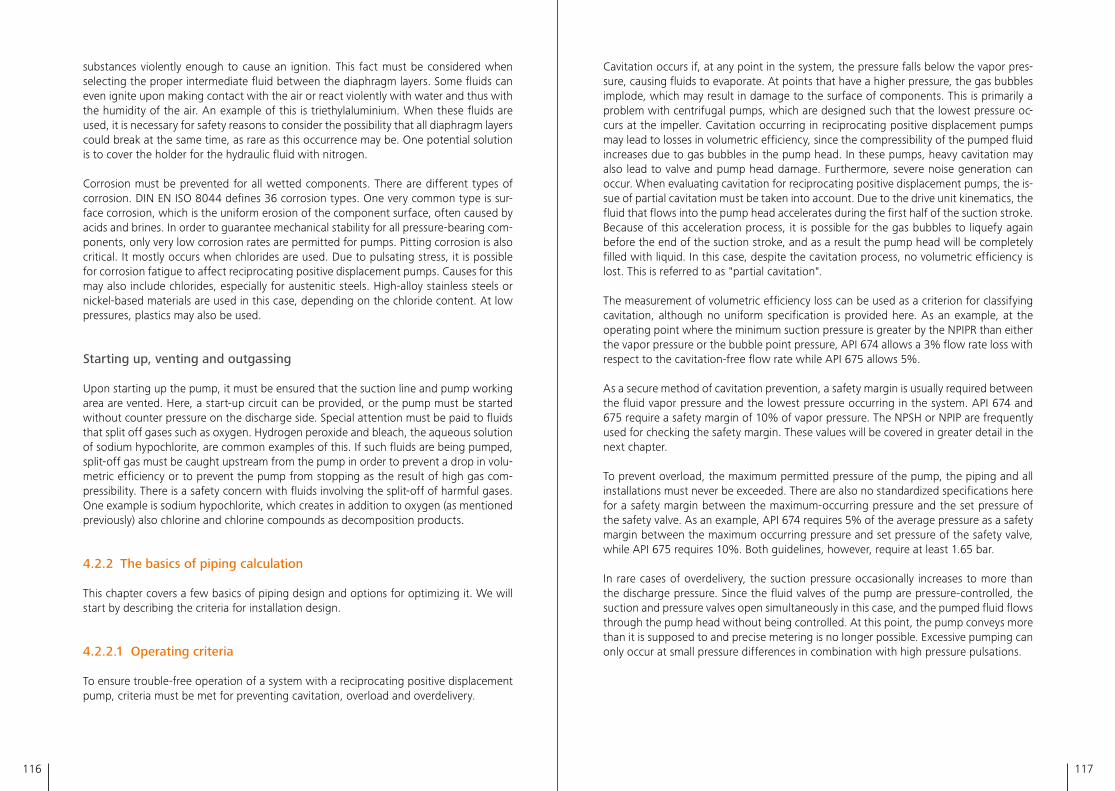
116 117
substances violently enough to cause an ignition� This fact must be considered when selecting the proper intermediate fluid between the diaphragm layers� Some fluids can even ignite upon making contact with the air or react violently with water and thus with the humidity of the air� An example of this is triethylaluminium� When these fluids are used, it is necessary for safety reasons to consider the possibility that all diaphragm layers could break at the same time, as rare as this occurrence may be� One potential solution is to cover the holder for the hydraulic fluid with nitrogen�
Corrosion must be prevented for all wetted components� There are different types of corrosion� DIN EN ISO 8044 defines 36 corrosion types� One very common type is sur-face corrosion, which is the uniform erosion of the component surface, often caused by acids and brines� In order to guarantee mechanical stability for all pressure-bearing com-ponents, only very low corrosion rates are permitted for pumps� Pitting corrosion is also critical� It mostly occurs when chlorides are used� Due to pulsating stress, it is possible for corrosion fatigue to affect reciprocating positive displacement pumps� Causes for this may also include chlorides, especially for austenitic steels� High-alloy stainless steels or nickel-based materials are used in this case, depending on the chloride content� At low pressures, plastics may also be used�
Starting up, venting and outgassing
Upon starting up the pump, it must be ensured that the suction line and pump working area are vented� Here, a start-up circuit can be provided, or the pump must be started without counter pressure on the discharge side� Special attention must be paid to fluids that split off gases such as oxygen� Hydrogen peroxide and bleach, the aqueous solution of sodium hypochlorite, are common examples of this� If such fluids are being pumped, split-off gas must be caught upstream from the pump in order to prevent a drop in volu-metric efficiency or to prevent the pump from stopping as the result of high gas com-pressibility� There is a safety concern with fluids involving the split-off of harmful gases� One example is sodium hypochlorite, which creates in addition to oxygen (as mentioned previously) also chlorine and chlorine compounds as decomposition products�
4.2.2 The basics of piping calculation
This chapter covers a few basics of piping design and options for optimizing it� We will start by describing the criteria for installation design�
4.2.2.1 Operating criteria
To ensure trouble-free operation of a system with a reciprocating positive displacement pump, criteria must be met for preventing cavitation, overload and overdelivery�
Cavitation occurs if, at any point in the system, the pressure falls below the vapor pres-sure, causing fluids to evaporate� At points that have a higher pressure, the gas bubbles implode, which may result in damage to the surface of components� This is primarily a problem with centrifugal pumps, which are designed such that the lowest pressure oc-curs at the impeller� Cavitation occurring in reciprocating positive displacement pumps may lead to losses in volumetric efficiency, since the compressibility of the pumped fluid increases due to gas bubbles in the pump head� In these pumps, heavy cavitation may also lead to valve and pump head damage� Furthermore, severe noise generation can occur� When evaluating cavitation for reciprocating positive displacement pumps, the is-sue of partial cavitation must be taken into account� Due to the drive unit kinematics, the fluid that flows into the pump head accelerates during the first half of the suction stroke� Because of this acceleration process, it is possible for the gas bubbles to liquefy again before the end of the suction stroke, and as a result the pump head will be completely filled with liquid� In this case, despite the cavitation process, no volumetric efficiency is lost� This is referred to as "partial cavitation"�
The measurement of volumetric efficiency loss can be used as a criterion for classifying cavitation, although no uniform specification is provided here� As an example, at the operating point where the minimum suction pressure is greater by the NPIPR than either the vapor pressure or the bubble point pressure, API 674 allows a 3% flow rate loss with respect to the cavitation-free flow rate while API 675 allows 5%�
As a secure method of cavitation prevention, a safety margin is usually required between the fluid vapor pressure and the lowest pressure occurring in the system� API 674 and 675 require a safety margin of 10% of vapor pressure� The NPSH or NPIP are frequently used for checking the safety margin� These values will be covered in greater detail in the next chapter�
To prevent overload, the maximum permitted pressure of the pump, the piping and all installations must never be exceeded� There are also no standardized specifications here for a safety margin between the maximum-occurring pressure and the set pressure of the safety valve� As an example, API 674 requires 5% of the average pressure as a safety margin between the maximum occurring pressure and set pressure of the safety valve, while API 675 requires 10%� Both guidelines, however, require at least 1�65 bar�
In rare cases of overdelivery, the suction pressure occasionally increases to more than the discharge pressure� Since the fluid valves of the pump are pressure-controlled, the suction and pressure valves open simultaneously in this case, and the pumped fluid flows through the pump head without being controlled� At this point, the pump conveys more than it is supposed to and precise metering is no longer possible� Excessive pumping can only occur at small pressure differences in combination with high pressure pulsations�
118 119
4.2.2.2 NPSH/NPIP
The suction side is checked using the NPSH or NPIP for each pump design�
NPSH
The abbreviation NPSH stands for "net positive suction head" and refers to a difference in pressure� This pressure difference is converted to the height of the corresponding fluid column of the pumped fluid� NPSH is usually specified in meters m or in feet ft� A distinction is made between the NPSHA value that is available on the suction side (net positive suction head available) and the NPSHR value required by the pump (net positive suction head required)�
The NPSHA is determined on the pump flange and describes the differential pressure between the static process pressure there and the vapor pressure of the pumped fluid� It includes all static pressure losses between the suction tank and the pump, the pressure level in the tank as well as the geodetic height differences between the fluid level in the suction tank and the pump�
The pressure losses that occur during inflow into the pumps are summarized in the NPSHR� The NPSHR is determined by the pump manufacturer for a certain speed, a cer-tain flow rate and a certain fluid�
It must be noted that the evaluation of the suction side using the NPSH only takes into account the static losses of the pumped fluid� This is sufficient for pump designs with constant flow rates� For operation, it must be ensured that the NPSHA is at least as large as the NPSHR in order to prevent a dramatic drop in flow rate or even damage due to pump cavitation�
The NPSH alone is not an adequate criterion for evaluating reciprocating pumps due to their pulsating flow rate� Furthermore, it is not adequate for evaluating hydraulically driv-en diaphragm pumps due to losses on the hydraulic side� Using the NPIP is more appro-priate for a comprehensive review� It is described in more detail in the following section�
NPIP
The abbreviation NPIP stands for "net positive inlet pressure"� The NPIP is similar to NPSH in that both describe a pressure difference� However, NPIP is not translated into a height, but is rather specified directly as pressure� The conventional unit for the NPIP is bar or psi� Similarly to the NPSH value, the NPIP distinguishes between an NPIPA value provided by the system (net positive inlet pressure available) and an NPIPR value required by the pump (net positive inlet pressure required)� Both values are specified for the operating states on the pump flange�
The NPIPA value specifies the pressure difference between the vapor pressure and the lowest process pressure occurring during operation� In addition to static pressure losses, this also includes the dynamic pressure losses for the pumped fluid on the suction side�The NPIPR value denotes the pressure difference relative to the vapor pressure neces-sary to ensure continuous operation without a drop in flow rate� In addition to pressure losses during inflow, this also takes into account possible losses on the hydraulic side of the pump as well as other phenomena which may affect the flow rate depending on the design of the diaphragm pump� The MRSP (minimum required suction pressure) is also frequently referred to in connection with the NPIPR� It is equal to the vapor pressure plus the NPIPR and is specified in terms of absolute pressure� The NPIPR or MRSP is determined by the pump manufacturer for a certain speed, a certain flow rate and a certain fluid�
For operation, it must be ensured that the NPIPA is at least as high as the NPIPR in order to prevent a dramatic drop in the flow rate and, in the worst-case scenario, to prevent damage to the pump due to cavitation�
An advantage of using NPIP instead of NPSH is that all losses are taken into account�
In a simplified analytic calculation, these pressure losses are divided into friction pressure losses and acceleration pressure fluctuation� Acceleration pressure fluctuation will be described in more precise detail in the following chapter "Fluid mechanics and design of piping"� In Appendix E of API 674 and 675 a very simplified calculation model for acceleration pressure fluctuation is provided� The model defines factors for the pump kinematics and calculates the relative compressibility independently of fluid, temperature and pressure� Factor C, which accounts for the number of pump heads, also differs be-tween API 674 and API 675� Calculation programs that calculate the kinematics of the re-spective pump and the compressibility of the respective fluid can provide better results�
Figure 4�6 depicts a suction-side pressure curve from an analytical simulation� The NPIP values can be read directly from the pressure curve�
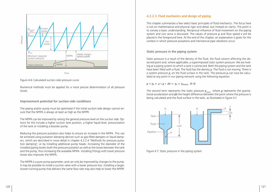
120 121
Time
Pres
sure
Acc.losses
Frictionlosses
Safety margin:NPIPA-NPIPR
pmean
pmin
NPIPAMinimum required suction pressure
Vapor pressure
psuction static
NPIPR
Figure 4�6: Calculated suction-side pressure curve
Numerical methods must be applied for a more precise determination of all pressure losses�
Improvement potential for suction-side conditions
The piping and/or pump must be optimized if the initial suction-side design cannot en-sure that the NPIPA is always at least as high as the NPIPR�
The NPIPA can be improved by raising the general pressure level on the suction side� Op-tions for this include a higher suction tank position, a higher liquid level, pressurization of the tank or installing a booster pump�
Reducing the pressure pulsation also helps to ensure an increase in the NPIPA� This can be achieved using pulsation damping devices such as gas-filled dampers or liquid damp-ers, which are described in more detail in chapter 4�2�2�4 "Methods for pressure pulsa-tion damping", or by installing additional pump heads� Increasing the diameter of the installed piping lowers both the pressure pulsation as well as the losses between the tank and the pump, thus increasing the available NPIPA� Installing fittings with lower pressure losses also improves the NPIPA�
The NPIPR is a pure pump parameter, and can only be improved by changes to the pump� It may be possible to install a suction valve with a lower pressure loss� Installing a larger, slower-running pump that delivers the same flow rate may also help to lower the NPIPR�
4.2.2.3 Fluid mechanics and design of piping
This chapter summarizes a few select basic principles of fluid mechanics� The focus here is not on mathematical and physical rigor and detail, but instead on clarity� The point is to convey a basic understanding� Reciprocal influence of fluid movement on the piping system and vice versa is discussed� The values of pressure p and flow speed v will be placed in the foreground here� At the end of the chapter, an explanation is given for the context in which pressure pulsations and mechanical pipe vibrations occur�
Static pressure in the piping system
Static pressure is a result of the density of the fluid, the fluid column affecting the ob-served point and, where applicable, a superimposed static system pressure� We are look-ing at a piping system to which a tank is connected� Both the piping system and the tank have been filled with a fluid� The fluid has the density ρ� The fluid is not moving� There is a system pressure pt on the fluid surface in the tank� The pressure p can now be calcu-lated at any point in our piping network using the following equation:
(4-4)
The second term represents the static pressure pstatic , where g represents the gravita-tional acceleration and Δh the height difference between the point where the pressure is being calculated and the fluid surface in the tank, as illustrated in figure 4�7�
Tank
Fluid+∆h
–∆h
Pipeline
pt pt
p
p
Figure 4�7: Static pressure in the piping system
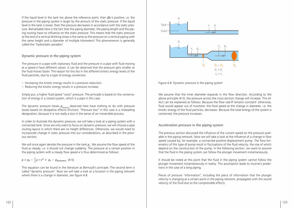
122 123
If the liquid level in the tank lies above the reference point, then Δh is positive; i�e� the pressure in the piping system is larger by the amount of the static pressure� If the liquid level in the tank is lower, then the pressure decreases in accordance with the static pres-sure� Remarkable here is the fact that the piping diameter, the piping length and the pip-ing routing have no influence on the static pressure� This means that the static pressure at the end of a vertical drinking straw is the same as the pressure on a vertical piping with the same height and a diameter of multiple kilometers! This phenomenon is generally called the "hydrostatic paradox"�
Dynamic pressure in the piping system
The pressure in a pipe with stationary fluid and the pressure in a pipe with fluid moving at a speed v have different values� It can be observed that the pressure gets smaller as the fluid moves faster� The reason for this lies in the different kinetic energy levels of the fluid particles, due to a type of energy conversion�
– Increasing the kinetic energy results in a pressure reduction�– Reducing the kinetic energy results in a pressure increase�
Simply put, a higher fluid speed "costs" pressure� The principle is based on the conserva-tion of energy in a closed system, which is a pipe in this case�
The dynamic pressure losses pdynamic observed here have nothing to do with pressure losses based on dissipative effects (friction)� "Pressure loss" in this case is a misleading designation, because it is not really a loss in the sense of an irreversible process�
In order to illustrate the dynamic pressure, we will take a look at a piping system with a connected tank� Since we only want to focus on dynamic pressure, we will choose a pipe routing layout in which there are no height differences� Otherwise, we would need to incorporate change in static pressure into our considerations, as described in the previ-ous section�
We will once again denote the pressure in the tank pt � We assume the flow speed of the fluid as steady, i�e� it should not change suddenly� The pressure at a certain position in the piping system with a steady flow speed v is thus determined as follows:
(4-5)
This equation can be found in the literature as Bernoulli's principle� The second term is called "dynamic pressure"� Now we will take a look at a location in the piping network where there is a change in diameter, see figure 4�8�
Tank
Fluid
pt
pt
p1v1
Q1 Q1 = Q2
p1 < p2
v1 > v2
Q2
p2v2
pv
Figure 4�8: Dynamic pressure in the piping system
We assume that the inner diameter expands in the flow direction� According to the above principle (4-5), the pressure across the cross-section change will increase� This ef-fect can be explained as follows: Because the flow rate remains constant- otherwise, fluid would appear out of nowhere- the fluid speed at the change in diameter, i�e� the kinetic energy of the fluid particles, decreases� Because the total energy of the system is conserved, the pressure increases�
Acceleration pressure in the piping system
The previous section discussed the influence of the current speed on the pressure avail-able in the piping network� Now we will take a look at the influence of a change in flow speed caused by, for example, a connected positive displacement pump� The flow kin-ematics of this type of pump result in fluctuations of the fluid velocity, the size of which depend on the construction of the pump� In the following section, we want to assume that the fluid in the piping system can follow the plunger movement instantaneously� It should be noted at this point that the fluid in the piping system cannot follow the plunger movement instantaneously in reality� This assumption leads to incorrect predic-tions in the case of a long piping�
Pieces of pressure "information", including the piece of information that the plunger velocity is changing at a certain point in the piping network, propagates with the sound velocity of the fluid due to the compressible effects�
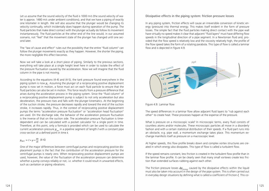
124 125
Let us assume that the sound velocity of the fluid is 1000 m/s (the sound velocity of wa-ter is approx� 1480 m/s under ambient conditions), and that we have a piping of exactly one kilometer in length� We will also assume that the plunger would be changing its velocity continually, which incidentally does happen during operation of the pump� The fluid particles that make direct contact with the plunger actually do follow its movement instantaneously� The fluid particles at the other end of the line would, in our assumed scenario, not "feel" that the movement state of the plunger has changed until one sec-ond later�
The "law of cause and effect" rules out the possibility that the entire "fluid column" can follow the plunger movements exactly as they happen� However, the shorter the piping, the more negligible this effect becomes�
Now we will take a look at a short piece of piping� Similarly to the previous sections, everything will take place at a single height level here in order to isolate the effect of the pressure fluctuation caused by the acceleration� Now we will imagine that the fluid column in the pipe is not moving�
According to the equations (4-4) and (4-5), the tank pressure found everywhere in the piping system is now pt� Assuming the plunger of a reciprocating positive displacement pump is now set in motion, a force must act on each fluid particle to ensure that the fluid particles can also be set in motion� This force results from a pressure difference that arises during the acceleration process in the piping system� Since the "fluid column" of a reciprocating positive displacement pump is subject to not only acceleration but also deceleration, the pressure rises and falls with the plunger kinematics� At the beginning of the suction stroke, the pressure decreases rapidly and toward the end of the suction stroke, it increases rapidly� Thus, in the context of reciprocating positive displacement pumps the terms "acceleration pressure fluctuation" or "acceleration head fluctuation" are used� On the discharge side, the behavior of the acceleration pressure fluctuation is the inverse of that on the suction side� The acceleration pressure fluctuation is time-dependent and can be calculated with a pocket calculator for a single point in time� Therefore, at this point, only a formula is provided which can be used to calculate the current acceleration pressure pacc in a pipeline segment of length l with a constant pipe cross-section at a defined point in time t�
(4-6)
One of the major differences between centrifugal pumps and reciprocating positive dis-placement pumps is the fact that the contribution of the acceleration pressure for the centrifugal pumps is nearly zero� When reciprocating positive displacement pumps are used, however, the value of the fluctuation of the acceleration pressure can determine whether a pump conveys reliably or not, i�e� whether it could result in unwanted effects, such as cavitation or piping vibrations�
Dissipative effects in the piping system: friction pressure losses
In any piping system, friction effects will cause an irreversible conversion of kinetic en-ergy (pressure) into thermal energy� This makes itself evident in the form of pressure losses� The simple fact that the fluid particles making direct contact with the pipe wall have virtually no speed makes it clear that adjacent "fluid layers" must have differing flow speeds in the longitudinal direction of a pipe segment� In a Newtonian fluid and, pro-vided that the flow speed is relatively low and the viscosity relatively high, the profile of the flow speed takes the form of a rotating parabola� This type of flow is called a laminar flow and is depicted in figure 4�9�
v1v2
v3
v2v1
Flow speeds
Pipe
Figure 4�9: Laminar flow
The speed differences in a laminar flow allow adjacent fluid layers to "rub against each other" to create heat� These processes happen at the expense of the pressure�
What is pressure on a microscopic scale? In microscopic terms, every fluid consists of countless atoms and/or molecules� These microscopic particles all move in a disorderly fashion and with a certain statistical distribution of their speeds� If a fluid part runs into an obstacle, e�g� pipe wall, a momentum exchange takes place� This momentum ex-change manifests itself as pressure on a macroscopic level�
At higher speeds, this flow profile breaks down and complex vortex structures are cre-ated in which energy also dissipates� This type of flow is called a turbulent flow�
If the speed remains constant, less friction is created in the turbulent flow profile than in the laminar flow profile� It can be clearly seen that many small vortexes create less fric-tion than extended surfaces rubbing against each other�
The friction pressure losses Δpfriction caused by the dissipative effects within the liquid must also be taken into account in the design of the pipe system� This is often carried out in everyday design situations by defining what is called a coefficient of friction ζ� This co-
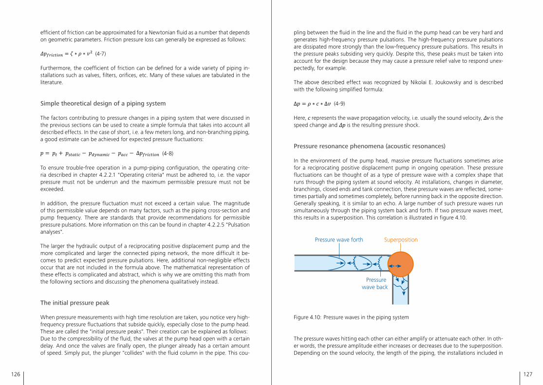
126 127
efficient of friction can be approximated for a Newtonian fluid as a number that depends on geometric parameters� Friction pressure loss can generally be expressed as follows:
(4-7)
Furthermore, the coefficient of friction can be defined for a wide variety of piping in-stallations such as valves, filters, orifices, etc� Many of these values are tabulated in the literature�
Simple theoretical design of a piping system
The factors contributing to pressure changes in a piping system that were discussed in the previous sections can be used to create a simple formula that takes into account all described effects� In the case of short, i�e� a few meters long, and non-branching piping, a good estimate can be achieved for expected pressure fluctuations:
(4-8)
To ensure trouble-free operation in a pump-piping configuration, the operating crite-ria described in chapter 4�2�2�1 "Operating criteria" must be adhered to, i�e� the vapor pressure must not be underrun and the maximum permissible pressure must not be exceeded�
In addition, the pressure fluctuation must not exceed a certain value� The magnitude of this permissible value depends on many factors, such as the piping cross-section and pump frequency� There are standards that provide recommendations for permissible pressure pulsations� More information on this can be found in chapter 4�2�2�5 "Pulsation analyses"�
The larger the hydraulic output of a reciprocating positive displacement pump and the more complicated and larger the connected piping network, the more difficult it be-comes to predict expected pressure pulsations� Here, additional non-negligible effects occur that are not included in the formula above� The mathematical representation of these effects is complicated and abstract, which is why we are omitting this math from the following sections and discussing the phenomena qualitatively instead�
The initial pressure peak
When pressure measurements with high time resolution are taken, you notice very high-frequency pressure fluctuations that subside quickly, especially close to the pump head� These are called the "initial pressure peaks"� Their creation can be explained as follows:Due to the compressibility of the fluid, the valves at the pump head open with a certain delay� And once the valves are finally open, the plunger already has a certain amount of speed� Simply put, the plunger "collides" with the fluid column in the pipe� This cou-
pling between the fluid in the line and the fluid in the pump head can be very hard and generates high-frequency pressure pulsations� The high-frequency pressure pulsations are dissipated more strongly than the low-frequency pressure pulsations� This results in the pressure peaks subsiding very quickly� Despite this, these peaks must be taken into account for the design because they may cause a pressure relief valve to respond unex-pectedly, for example�
The above described effect was recognized by Nikolai E� Joukowsky and is described with the following simplified formula:
(4-9)
Here, c represents the wave propagation velocity, i�e� usually the sound velocity, Δv is the speed change and Δp is the resulting pressure shock�
Pressure resonance phenomena (acoustic resonances)
In the environment of the pump head, massive pressure fluctuations sometimes arise for a reciprocating positive displacement pump in ongoing operation� These pressure fluctuations can be thought of as a type of pressure wave with a complex shape that runs through the piping system at sound velocity� At installations, changes in diameter, branchings, closed ends and tank connection, these pressure waves are reflected, some-times partially and sometimes completely, before running back in the opposite direction� Generally speaking, it is similar to an echo� A large number of such pressure waves run simultaneously through the piping system back and forth� If two pressure waves meet, this results in a superposition� This correlation is illustrated in figure 4�10�
SuperpositionPressure wave forth
Pressure wave back
Figure 4�10: Pressure waves in the piping system
The pressure waves hitting each other can either amplify or attenuate each other� In oth-er words, the pressure amplitude either increases or decreases due to the superposition� Depending on the sound velocity, the length of the piping, the installations included in
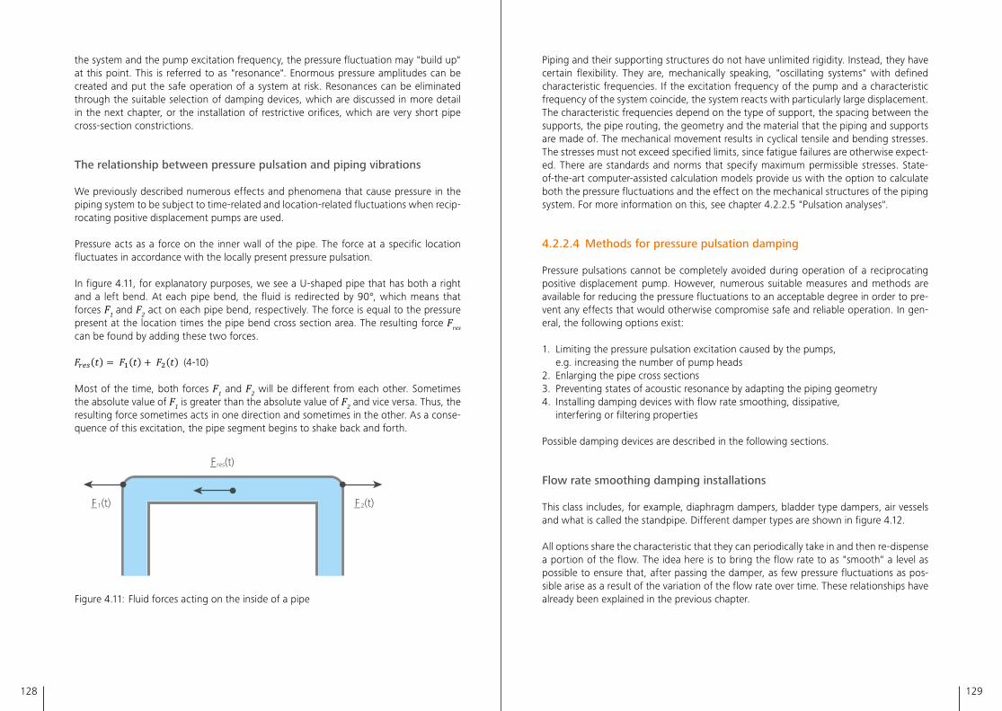
128 129
the system and the pump excitation frequency, the pressure fluctuation may "build up" at this point� This is referred to as "resonance"� Enormous pressure amplitudes can be created and put the safe operation of a system at risk� Resonances can be eliminated through the suitable selection of damping devices, which are discussed in more detail in the next chapter, or the installation of restrictive orifices, which are very short pipe cross-section constrictions�
The relationship between pressure pulsation and piping vibrations
We previously described numerous effects and phenomena that cause pressure in the piping system to be subject to time-related and location-related fluctuations when recip-rocating positive displacement pumps are used�
Pressure acts as a force on the inner wall of the pipe� The force at a specific location fluctuates in accordance with the locally present pressure pulsation�
In figure 4�11, for explanatory purposes, we see a U-shaped pipe that has both a right and a left bend� At each pipe bend, the fluid is redirected by 90°, which means that forces F1 and F2 act on each pipe bend, respectively� The force is equal to the pressure present at the location times the pipe bend cross section area� The resulting force Fres can be found by adding these two forces�
(4-10)
Most of the time, both forces F1 and F2 will be different from each other� Sometimes the absolute value of F1 is greater than the absolute value of F2 and vice versa� Thus, the resulting force sometimes acts in one direction and sometimes in the other� As a conse-quence of this excitation, the pipe segment begins to shake back and forth�
F_res(t)
F_1(t) F_2(t)
Figure 4�11: Fluid forces acting on the inside of a pipe
Piping and their supporting structures do not have unlimited rigidity� Instead, they have certain flexibility� They are, mechanically speaking, "oscillating systems" with defined characteristic frequencies� If the excitation frequency of the pump and a characteristic frequency of the system coincide, the system reacts with particularly large displacement� The characteristic frequencies depend on the type of support, the spacing between the supports, the pipe routing, the geometry and the material that the piping and supports are made of� The mechanical movement results in cyclical tensile and bending stresses� The stresses must not exceed specified limits, since fatigue failures are otherwise expect-ed� There are standards and norms that specify maximum permissible stresses� State-of-the-art computer-assisted calculation models provide us with the option to calculate both the pressure fluctuations and the effect on the mechanical structures of the piping system� For more information on this, see chapter 4�2�2�5 "Pulsation analyses"�
4.2.2.4 Methods for pressure pulsation damping
Pressure pulsations cannot be completely avoided during operation of a reciprocating positive displacement pump� However, numerous suitable measures and methods are available for reducing the pressure fluctuations to an acceptable degree in order to pre-vent any effects that would otherwise compromise safe and reliable operation� In gen-eral, the following options exist:
1� Limiting the pressure pulsation excitation caused by the pumps, e�g� increasing the number of pump heads
2� Enlarging the pipe cross sections3� Preventing states of acoustic resonance by adapting the piping geometry4� Installing damping devices with flow rate smoothing, dissipative,
interfering or filtering properties
Possible damping devices are described in the following sections�
Flow rate smoothing damping installations
This class includes, for example, diaphragm dampers, bladder type dampers, air vessels and what is called the standpipe� Different damper types are shown in figure 4�12�
All options share the characteristic that they can periodically take in and then re-dispense a portion of the flow� The idea here is to bring the flow rate to as "smooth" a level as possible to ensure that, after passing the damper, as few pressure fluctuations as pos-sible arise as a result of the variation of the flow rate over time� These relationships have already been explained in the previous chapter�
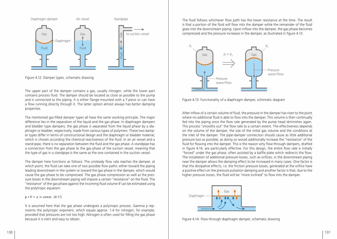
130 131
Fluid
Gas
Fluid
Gas
Diaphragm damper
Flui
dG
as
Diaphragm
Air vessel Standpipe
to suction vessel
Figure 4�12: Damper types, schematic drawing
The upper part of the damper contains a gas, usually nitrogen, while the lower part contains process fluid� The damper should be located as close as possible to the pump and is connected to the piping� It is either flange-mounted with a T-piece or can have a flow running directly through it� The latter option almost always has better damping properties�
The mentioned gas-filled damper types all have the same working principle� The major difference lies in the separation of the liquid and the gas phase� In diaphragm dampers and bladder type dampers, the gas phase is separated from the liquid phase by a dia-phragm or bladder, respectively, made from various types of polymers� These two damp-er types differ in terms of constructional design and the diaphragm or bladder material, which is chosen according the chemical reactiveness of the fluid� In an air vessel and a stand-pipe, there is no separation between the fluid and the gas phase� A standpipe has a connection from the gas phase to the gas phase of the suction vessel, meaning that the type of gas in a standpipe is the same as the one contained in the suction vessel�
The damper here functions as follows: The unsteady flow rate reaches the damper, at which point, the fluid can take one of two possible flow paths: either toward the piping leading downstream in the system or toward the gas phase in the damper, which would cause the gas phase to be compressed� The gas phase compression as well as the pres-sure losses in the downstream piping will impose a certain "resistance" on the fluid� The "resistance" of the gas phase against the incoming fluid volume V can be estimated using the polytropic equation:
(4-11)
It is assumed here that the gas phase undergoes a polytropic process� Gamma γ rep-resents the polytropic exponent, which equals approx� 1�4 for nitrogen, for example, provided that pressures are not too high� Nitrogen is often used for filling the gas phase because it is inert and easy to obtain�
The fluid follows whichever flow path has the lower resistance at the time� The result is that a portion of the fluid will flow into the damper while the remainder of the fluid goes into the downstream piping� Upon inflow into the damper, the gas phase becomes compressed and the pressure increases in the damper, as illustrated in figure 4�13�
Gas Gas
p1
p1 < p2
p2
Pressure wave / Flow
Pressure wave / Flow
Figure 4�13: Functionality of a diaphragm damper, schematic diagram
After inflow of a certain volume of fluid, the pressure in the damper has risen to the point where no additional fluid is able to flow into the damper� This volume is then continually fed into the piping once the flow rate generated by the pump head diminishes again� This process "smooths out" the flow rate to a certain extent� The effectiveness depends on the volume of the damper, the size of the initial gas volume and the conditions at the inlet of the damper� The pipe-damper connection should cause as little additional pressure loss as possible, as doing so would additionally increase the "resistance" of the fluid for flowing into the damper� This is the reason why flow-through dampers, drafted in figure 4�14, are particularly effective� For this design, the entire flow rate is initially "forced" under the gas phase, often assisted by a baffle plate which redirects the flow� The installation of additional pressure losses, such as orifices, in the downstream piping near the damper allows the damping effect to be increased in many cases� One factor is that the dissipative effects, i�e� the friction pressure losses, generated at the orifice have a positive effect on the pressure pulsation damping and another factor is that, due to the higher pressure losses, the fluid will be "more inclined" to flow into the damper�
DiaphragmGas
Figure 4�14: Flow-through diaphragm damper, schematic drawing
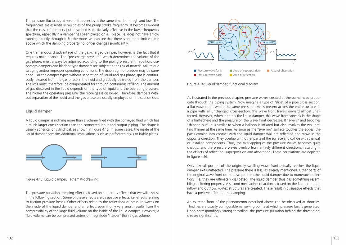
132 133
The pressure fluctuates at several frequencies at the same time, both high and low� The frequencies are essentially multiples of the pump stroke frequency� It becomes evident that the class of dampers just described is particularly effective in the lower frequency spectrum, especially if a damper has been placed on a T-piece, i�e� does not have a flow running directly through it� Furthermore, we can see that there is an upper limit volume above which the damping property no longer changes significantly�
One tremendous disadvantage of the gas-charged damper, however, is the fact that it requires maintenance� The "pre-charge pressure", which determines the volume of the gas phase, must always be adjusted according to the piping pressure� In addition, dia-phragm dampers and bladder type dampers are subject to the risk of material failure due to aging and/or improper operating conditions� The diaphragm or bladder may be dam-aged� For the damper types without separation of liquid and gas phase, gas is continu-ously released from the gas phase in the fluid and gradually delivered from the damper� The loss must, therefore, be compensated for through continuous refilling� The amount of gas dissolved in the liquid depends on the type of liquid and the operating pressure� The higher the operating pressure, the more gas is dissolved� Therefore, dampers with-out separation of the liquid and the gas phase are usually employed on the suction side�
Liquid damper
A liquid damper is nothing more than a volume filled with the conveyed fluid which has a much larger cross-section than the connected input and output piping� The shape is usually spherical or cylindrical, as shown in figure 4�15� In some cases, the inside of the liquid damper contains additional installations, such as perforated disks or baffle plates�
Figure 4�15: Liquid dampers, schematic drawing
The pressure pulsation damping effect is based on numerous effects that we will discuss in the following section� Some of these effects are dissipative effects, i�e� effects relating to friction pressure losses� Other effects relate to the reflections of pressure waves on the inside of the liquid damper and an effect, even if only very small, results from the compressibility of the large fluid volume on the inside of the liquid damper� However, a fluid volume can be compressed orders of magnitude "harder" than a gas volume�
∆p
t
∆p
t
Area of superpositionArea of reflection
Area of absorbtionPressure wave forthPressure wave back
Figure 4�16: Liquid damper, functional diagram
As illustrated in the previous chapter, pressure waves created at the pump head propa-gate through the piping system� Now imagine a type of "slice" of a pipe cross-section, a flat wave front, where the same pressure level is present across the entire surface� In a pipe with an unchanged cross-section, this wave front travels onward almost unaf-fected� However, when it enters the liquid damper, this wave front spreads in the shape of a half-sphere and the pressure on the wave front decreases� It "swells" and becomes "thinned out"� It is similar to when a balloon is inflated but also involves the wall get-ting thinner at the same time� As soon as the "swelling" surface touches the edges, the parts coming into contact with the liquid damper wall are reflected and move in the opposite direction� They overlap with other parts of the surface and collide with the wall or installed components� Thus, the overlapping of the pressure waves becomes quite chaotic, and the pressure waves overlap from entirely different directions, resulting in the effects of reflection, superposition and absorption� These correlations are depicted in figure 4�16�
Only a small portion of the originally swelling wave front actually reaches the liquid damper exit unaffected� The pressure there is less, as already mentioned� Other parts of the original wave front do not escape from the liquid damper due to numerous deflec-tions, i�e� they are ultimately dissipated� The liquid damper thus has something resem-bling a filtering property� A second mechanism of action is based on the fact that, upon inflow and outflow, vortex structures are created� These result in dissipative effects that have a positive effect on the damping�
An extreme form of the phenomenon described above can be observed at throttles� Throttles are usually configurable narrowing points at which pressure loss is generated� Upon correspondingly strong throttling, the pressure pulsation behind the throttle de-creases significantly�
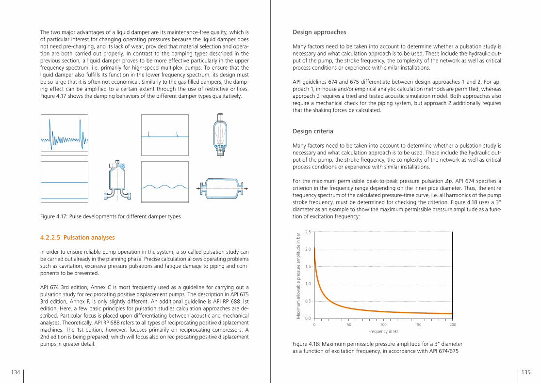
134 135
The two major advantages of a liquid damper are its maintenance-free quality, which is of particular interest for changing operating pressures because the liquid damper does not need pre-charging, and its lack of wear, provided that material selection and opera-tion are both carried out properly� In contrast to the damping types described in the previous section, a liquid damper proves to be more effective particularly in the upper frequency spectrum, i�e� primarily for high-speed multiplex pumps� To ensure that the liquid damper also fulfills its function in the lower frequency spectrum, its design must be so large that it is often not economical� Similarly to the gas-filled dampers, the damp-ing effect can be amplified to a certain extent through the use of restrictive orifices� Figure 4�17 shows the damping behaviors of the different damper types qualitatively�
Figure 4�17: Pulse developments for different damper types
4.2.2.5 Pulsation analyses
In order to ensure reliable pump operation in the system, a so-called pulsation study can be carried out already in the planning phase� Precise calculation allows operating problems such as cavitation, excessive pressure pulsations and fatigue damage to piping and com-ponents to be prevented�
API 674 3rd edition, Annex C is most frequently used as a guideline for carrying out a pulsation study for reciprocating positive displacement pumps� The description in API 675 3rd edition, Annex F, is only slightly different� An additional guideline is API RP 688 1st edition� Here, a few basic principles for pulsation studies calculation approaches are de-scribed� Particular focus is placed upon differentiating between acoustic and mechanical analyses� Theoretically, API RP 688 refers to all types of reciprocating positive displacement machines� The 1st edition, however, focuses primarily on reciprocating compressors� A 2nd edition is being prepared, which will focus also on reciprocating positive displacement pumps in greater detail�
Design approaches
Many factors need to be taken into account to determine whether a pulsation study is necessary and what calculation approach is to be used� These include the hydraulic out-put of the pump, the stroke frequency, the complexity of the network as well as critical process conditions or experience with similar installations�
API guidelines 674 and 675 differentiate between design approaches 1 and 2� For ap-proach 1, in-house and/or empirical analytic calculation methods are permitted, whereas approach 2 requires a tried and tested acoustic simulation model� Both approaches also require a mechanical check for the piping system, but approach 2 additionally requires that the shaking forces be calculated�
Design criteria
Many factors need to be taken into account to determine whether a pulsation study is necessary and what calculation approach is to be used� These include the hydraulic out-put of the pump, the stroke frequency, the complexity of the network as well as critical process conditions or experience with similar installations�
For the maximum permissible peak-to-peak pressure pulsation Δp, API 674 specifies a criterion in the frequency range depending on the inner pipe diameter� Thus, the entire frequency spectrum of the calculated pressure-time curve, i�e� all harmonics of the pump stroke frequency, must be determined for checking the criterion� Figure 4�18 uses a 3" diameter as an example to show the maximum permissible pressure amplitude as a func-tion of excitation frequency:
Frequency in Hz
Max
imum
allo
wab
le p
ress
ure
ampl
itude
in b
ar
0 50 100 150 200
2,5
2,0
1,5
1,0
0,5
0,0
Figure 4�18: Maximum permissible pressure amplitude for a 3" diameter as a function of excitation frequency, in accordance with API 674/675
136 137
In addition to the maximum pressure pulsation, the previously described safety margins from the vapor pressure and from the setting pressure of the pressure relief valve must be observed (see chapter 4�2�2�1 "Operating criteria")�
The guidelines do not contain any criteria for the permissible shaking forces of recipro-cating positive displacement pumps� API 618 5th edition, section 7�9 defines a criterion for reciprocating compressors depending on the frequency, the pipe diameter, the struc-tural stiffness and number of supports�
Pulsation analyses can also be carried out in accordance with customer-specific operat-ing criteria�
Mechanical analysis
For the mechanical check of the piping network, API 674 requires a span length calcula-tion� The theoretical basis for this calculation approach is the fact that each piping sec-tion, i�e� the distance between two supports, has a natural frequency depending on its diameter� This natural frequency must never coincide with the excitation frequency of the pump� This is why, for every diameter that occurs in the network, a maximum permissible span length between supports is to be calculated which has a natural frequency at least 20% greater than the maximum excitation frequency of the pump for the dominating harmonic� API 688 5th edition contains calculation methods for the natural frequencies of the piping under section 3�2�7�2�1� They can also be found in EDI Report 41450�
Pipe supports
In order to avoid vibrations, it must be ensured that the correct pipe supports are used� The Energy Institute provides a few guidelines in the publication "Guidelines for the Avoidance of Vibration Induced Fatigue Failure in Process Pipework", such as avoiding pipe bends to the greatest extent possible and attaching supports at heavy masses as well as near pipe bends� Rest and guide supports should be avoided because they cannot absorb dynamic forces� To ensure the ability to limit displacement, pipe supports must be "dynamically fixed"� Piping is considered dynamically fixed in one or more directions of movement and/or rotation if the support is capable of absorbing dynamic loads with-out allowing any movements relative to the support construction� This also means that no clearance is permissible between the piping and supporting construction� Rest type weight supports are therefore not an appropriate choice for piping systems subject to dynamic loads� The two technical solutions that can allow thermal expansion but pre-vent dynamic movements are clamp type support and hold down support� For absorbing dynamic forces, it must be ensured that the friction forces between the pipe support and the structure on which it is mounted are always greater than the shaking forces caused by the pressure pulsation�
Examples of clamp type supports and hold down supports can be found in API 688 5th edition in sections 3�2�7�9�1 and 3�2�7�9�2�
Caution is advised for connections with small diameters, which are often part of vent and drain pipes� Instructions for how to install these are found in API 688, Section 3�2�6�6� It is of crucial importance here to install overhanging masses close to the main pipe and to fasten them there�
4.3 Instrumentation and control engineering
4.3.1 Instrumentation
In the process engineering industry, the pump itself is never used alone�
Instruments for recording the following parameters are used:– Flow rate– Pressure (suction and process pressure)– Temperature (process, pump drive unit, etc�)– Level (tank, pipeline, etc�)– Media analysis, e�g� density, concentration
When selecting instruments, it is important to select the economically sensible and tech-nically sufficient instrument�
In addition to the instrument cost, the following aspects must be considered in this process:– Customer specifications– Physical state of the substance to be measured (liquid, gas, or mixture)– Pressure– Temperature – of the substance to be measured – of the environment– Ambient conditions– Density of the medium– Viscosity of the medium– Abrasiveness and corrosiveness of the medium– Conductivity – Measuring instruments for conductive liquids are often less expensive while offer-
ing the same accuracy, since these are frequently used in waste water technology�– Required measuring accuracy and reproducibility including measuring dynamics– Process connection– Mechanical requirements such as inlet run, installation position, etc�– Potentially permissible pressure loss (for flow meters)– Current (flow), flow speed, and turbulence– Service life and failure probability
138 139
Furthermore, reliability, process safety and, finally, personal safety become more and more important� Newly developed instruments are evaluated in accordance with SIL (Safety Integrity Level based on the IEC 61508 standard) and usually developed from the beginning to meet SIL2 or even SIL3 regulations�
Monitoring mechanisms to ensure the correct measured value will be incorporated more and more into measuring instruments, and thus make the entire process more secure and more reliable� Examples of these mechanisms include adhesion monitoring for flow me-ters, the comparison of the current measuring behavior to the original behavior for Corio-lis flow meters, and more, in other words, self-monitoring of the measuring instrument�
4.3.2 Process control
Certain processes, such as foam extrusion, require very precise control that is as fast and easy as possible�
This is realized using either PID controllers or, nowadays, using an increasing number of programmable logic controllers (PLC) with PID control or characteristic curve control�
A PLC offers the advantage of flexibility, as well as a multilingual user interface and a con-nection to higher-level systems over a bus system or through the conventional method using analog and digital signals�
General control principle
For both systems, the flow rate is monitored by the controller or the PLC� The signal received from the control system is sent to the controller over a bus system or using the conventional method of a 4-20 mA signal as a reference value� The flow rate is meas-ured by the flow meter installed in the discharge line� The outgoing signal is sent to the controller as an actual value� The controller continually runs a setpoint/actual value com-parison� If a control deviation occurs, then the speed of the controllable pump motor is immediately changed using a frequency inverter, causing a constant adjustment of the flow rate� As an alternative to the frequency inverter, control can also be carried out us-ing an electric or pneumatic stroke adjustment or a combination of a frequency inverter and a drivable stroke adjustment�
How PID control differs from characteristic curve control
In the case of characteristic curve control, the pump characteristic curve is also provided to the controller upon system start-up� This gives the controller the option to calculate the manipulated variable for the frequency inverter or the stroke adjustment in advance, and to specify this calculated value of the manipulated variable as the starting value upon start-up of the control system or upon specification of a changed setpoint�
After the start-up of the actuator (frequency inverter/stroke adjustment), the PID con-trol system is then activated for adjusting the exact setpoint� This way, the setpoint is reached more quickly and without being severely overshot� The step response time is usually less than one minute, i�e� the specified setpoint is reached within one minute with a deviation of less than 1% of the specified value�
In addition, the characteristic curve controller is able to compare the actual value of the flow meter to the stored pump characteristic curve to determine whether the measure-ment is plausible� If a comparison value is not plausible, a message can be issued� This type of control is referred to as a self-monitoring system�
If the pump is adjusted through manual stroke adjustment, then the characteristic curve control can be influenced as follows:– Manual switch-off, at which point operation continues with PID control� – Entering new values for the characteristic curve, at which point control continues
normally with the new values�– Independent, adaptive recognition of a characteristic curve deviation by the control
system, at which point the system switches to PID control independently and registers the recalculated characteristic curve internally�
Additional integrated standard monitoring systems
A PLC can use pressure switches, contact pressure gauges, or pressure transmitters to monitor suction pressure and discharge pressure�
The monitoring of suction pressure is used to avoid pump cavitation and the monitoring of discharge pressure is used for system protection in addition to mechanical monitoring components such as overflow valves and pressure relief valves� If the preset maximum discharge pressure is exceeded, the pump is stopped, preventing the opening of the internal pressure relief valve�
Production data acquisition
Production data acquisition of figures such as operating hours, flow rates in combina-tion with a flow meter, and flow rate per day/week/month can also be integrated and transferred to a higher-level control system over a bus system�
Actuator data (e�g� of the frequency inverter, motor, or stroke adjustment) can also be transferred to the PLC or to a control system and analyzed� This type of analysis can then be used for preventive maintenance�
140 141
Expansion to the process system
For more complex fluid-related tasks, it is possible to expand the control algorithm through the addition of functions such as recipe management, fluid analysis, complex mixing processes, and temperature control�
Remote maintenance
Upon request or where more complex metering tasks are applied, it is also possible to equip the PLC with remote maintenance over internet/ethernet, turning it into a remote maintenance router� This allows the on-site commissioning to be supported by experi-enced commissioning personnel from the manufacturer’s headquarters�
To prevent unauthorized remote access, a secure VPN tunnel (virtual private network) is established using a remote maintenance router� This is carried out from the system side, i�e� the customer establishes the connection� The security can be increased by installing an additional manual on-site operation function, such as a key-operated switch, for ena-bling or disabling the remote access�
Diaphragm rupture monitoring
Standard diaphragm rupture monitoring systems can be designed as follows:– Purely visually using a pressure gauge– Electromechanically using pressure switches or contact pressure gauges, with a fixed
trigger value– Electronically using pressure transmitters and an adjustable switching threshold
There is also an option for adaptive diaphragm rupture monitoring using a solenoid valve in the case of diffusing fluids� A pressure transmitter can thereby be evaluated as follows:
– Good condition: – Pressure does not rise, or rises only slightly but continually� After a configurable
threshold, the pressure is released into the safe area using a solenoid valve� A maxi-mum rise time can be specified as "normal case"�
– Case of error: – Pressure rises very quickly and strongly; diaphragm rupture with alarm trigger� A
rise time "diaphragm rupture" can be specified� – Pressures of multiple heads of a multi-headed pump increase for the same fluid at
different speeds; the operator can adapt this previously unidentified warning using a parameter to turn it into an error with or without switch-off, or into a good condi-tion with pressure release via solenoid valve�
– Pressure does not rise only slightly, as would be assumed and as was conventional thus far, but does not rise suddenly either; the operator can adapt this previously unidentified warning using a parameter to turn it into an error with or without switch-off, or into a good condition with pressure relief via solenoid valve and the output of a message�
– Pressure does not rise at all, even though the pump is conveying; the operator can adapt this previously unidentified warning using a parameter to turn it into an error with or without switch-off, or into a good condition�
– Opening and closing the solenoid valve manually is always possible�
Batch control
Batch control is a modification of process control with respect to a certain filling task� Multiple variants of this modification are available:
The first is a simple, cost-effective version that counts only the pump strokes; a flow meter or a scale can be omitted� The control system calculates the necessary number of pump strokes on its own using the stored stroke volume� If the stroke volume of the pump head is changed by moving the stroke adjustment, then a calibration function can be used to define the new stroke volume�
The second version uses the mechanisms of process control via the flow meter or scale and frequency inverter and/or electric or pneumatic stroke adjustment� Here, the con-veyed fluid volume is determined and filled with precision� The filling precision and flex-ibility are both higher than those of the cost-effective version�
The third version is based on knowledge of the process and pump, and calculates the stroke volume� For this purpose, process data such as process pressure and motor data are taken into consideration� As with the first version, this version can omit a flow meter and a scale�
4.3.3 Condition monitoring systems
Condition monitoring systems (CMS) optimize the performance and service life of ma-chines and systems and increase their availability�
Condition-based and preventive maintenance improves the efficiency of machine and sys-tem operation� The costs of production failures are reduced thanks to early detection of damage, damage diagnostics, and predictable downtimes� This means that components do not need to be replaced until their conditions actually require it� Condition-based main-tenance replaces interval-based maintenance here, which was previously the standard pro-cedure�
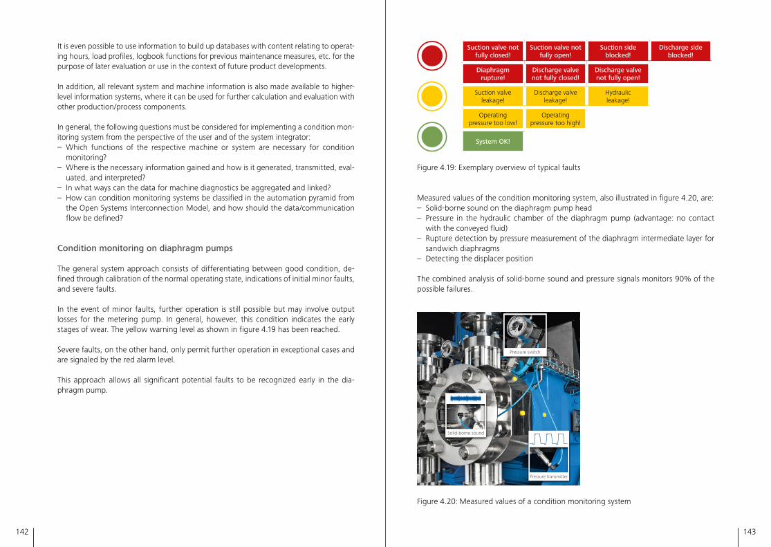
142 143
It is even possible to use information to build up databases with content relating to operat-ing hours, load profiles, logbook functions for previous maintenance measures, etc� for the purpose of later evaluation or use in the context of future product developments�
In addition, all relevant system and machine information is also made available to higher-level information systems, where it can be used for further calculation and evaluation with other production/process components�
In general, the following questions must be considered for implementing a condition mon-itoring system from the perspective of the user and of the system integrator:– Which functions of the respective machine or system are necessary for condition
monitoring?– Where is the necessary information gained and how is it generated, transmitted, eval-
uated, and interpreted?– In what ways can the data for machine diagnostics be aggregated and linked?– How can condition monitoring systems be classified in the automation pyramid from
the Open Systems Interconnection Model, and how should the data/communication flow be defined?
Condition monitoring on diaphragm pumps
The general system approach consists of differentiating between good condition, de-fined through calibration of the normal operating state, indications of initial minor faults, and severe faults�
In the event of minor faults, further operation is still possible but may involve output losses for the metering pump� In general, however, this condition indicates the early stages of wear� The yellow warning level as shown in figure 4�19 has been reached�
Severe faults, on the other hand, only permit further operation in exceptional cases and are signaled by the red alarm level�
This approach allows all significant potential faults to be recognized early in the dia-phragm pump�
Suction valve not fully closed!
Suction valve not fully open!
Suction side blocked!
Discharge side blocked!
Diaphragm rupture!
Discharge valve not fully closed!
Discharge valve not fully open!
Suction valve leakage!
Discharge valveleakage!
Hydraulic leakage!
Operating pressure too low!
Operatingpressure too high!
System OK!
Figure 4�19: Exemplary overview of typical faults
Measured values of the condition monitoring system, also illustrated in figure 4�20, are:– Solid-borne sound on the diaphragm pump head– Pressure in the hydraulic chamber of the diaphragm pump (advantage: no contact
with the conveyed fluid)– Rupture detection by pressure measurement of the diaphragm intermediate layer for
sandwich diaphragms– Detecting the displacer position
The combined analysis of solid-borne sound and pressure signals monitors 90% of the possible failures�
Solid-borne sound
Pressure transmitter
Pressure switch
Figure 4�20: Measured values of a condition monitoring system
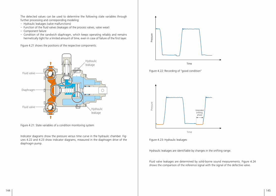
144 145
The detected values can be used to determine the following state variables through further processing and corresponding modeling:– Hydraulic leakages (valve malfunctions)– Function of the fluid valves (leakages of the process valves, valve wear)– Component failure– Condition of the sandwich diaphragm, which keeps operating reliably and remains
hermetically tight for a limited amount of time, even in case of failure of the first layer�
Figure 4�21 shows the positions of the respective components�
Fluid valve
Hydraulic leakage
Hydraulic leakage
Fluid valve
Diaphragm
Figure 4�21: State variables of a condition monitoring system
Indicator diagrams show the pressure versus time curve in the hydraulic chamber� Fig-ures 4�22 and 4�23 show indicator diagrams, measured in the diaphragm drive of the diaphragm pump�
Time
Pres
sure
Time
Pres
sure
Figure 4�22: Recording of "good condition"
Time
Pres
sure
Extendedsnifting phase
Figure 4�23: Hydraulic leakages
Hydraulic leakages are identifiable by changes in the snifting range�
Fluid valve leakages are determined by solid-borne sound measurements� Figure 4�24 shows the comparison of the reference signal with the signal of the defective valve�
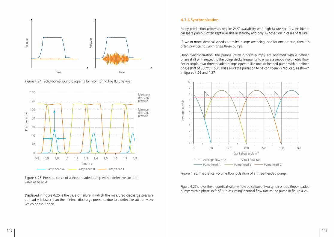
146 147
Time
Pres
sure
Time
Pres
sure
Time
Pres
sure
Time
Pres
sure
Figure 4�24: Solid-borne sound diagrams for monitoring the fluid valves
0,8 0,9 1,0 1,2 1,3 1,4 1,5 1,6 1,7 1,8
140
120
100
80
60
40
20
0
1,1
Time in s
Pres
sure
in b
ar
Pump head A Pump head B Pump head C
Maximumdischarge pressure
Minimumdischarge pressure
Figure 4�25: Pressure curve of a three-headed pump with a defective suction valve at head A
Displayed in figure 4�25 is the case of failure in which the measured discharge pressure at head A is lower than the minimal discharge pressure, due to a defective suction valve which doesn't open�
4.3.4 Synchronization
Many production processes require 24/7 availability with high failure security� An identi-cal spare pump is often kept available in standby and only switched on in cases of failure�
If two or more identical speed-controlled pumps are being used for one process, then it is often practical to synchronize these pumps�
Upon synchronization, the pumps (often process pumps) are operated with a defined phase shift with respect to the pump stroke frequency to ensure a smooth volumetric flow� For example, two three-headed pumps operate like one six-headed pump with a defined phase shift of 360°/6 = 60°� This allows the pulsation to be considerably reduced, as shown in figures 4�26 and 4�27�
0 60 120 180 240 300 360
0
1
2
3
4
5
6
7
8
9
10
Pump head A Pump head B Pump head C
Average flow rate Actual flow rate
Crank shaft angle in °
Flow
rate
in m
³/h
Figure 4�26: Theoretical volume flow pulsation of a three-headed pump
Figure 4�27 shows the theoretical volume flow pulsation of two synchronized three-headed pumps with a phase shift of 60°, assuming identical flow rate as the pump in figure 4�26�
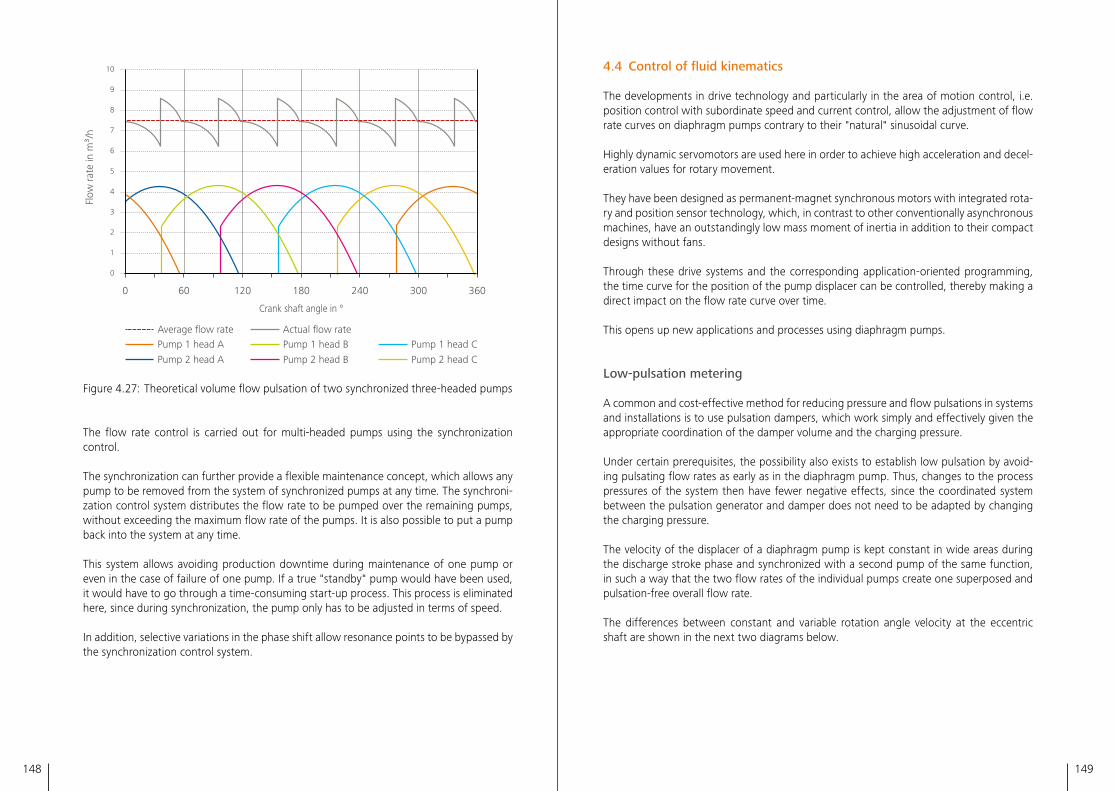
148 149
0 60 120 180 240 300 360
0
1
2
3
4
5
6
7
8
9
10
Average flow rate Actual flow rate Pump 1 head A Pump 1 head B Pump 1 head C
Pump 2 head A Pump 2 head B Pump 2 head C
Crank shaft angle in °
Flow
rate
in m
³/h
Figure 4�27: Theoretical volume flow pulsation of two synchronized three-headed pumps
The flow rate control is carried out for multi-headed pumps using the synchronization control�
The synchronization can further provide a flexible maintenance concept, which allows any pump to be removed from the system of synchronized pumps at any time� The synchroni-zation control system distributes the flow rate to be pumped over the remaining pumps, without exceeding the maximum flow rate of the pumps� It is also possible to put a pump back into the system at any time�
This system allows avoiding production downtime during maintenance of one pump or even in the case of failure of one pump� If a true "standby" pump would have been used, it would have to go through a time-consuming start-up process� This process is eliminated here, since during synchronization, the pump only has to be adjusted in terms of speed�
In addition, selective variations in the phase shift allow resonance points to be bypassed by the synchronization control system�
4.4 Control of fluid kinematics
The developments in drive technology and particularly in the area of motion control, i�e� position control with subordinate speed and current control, allow the adjustment of flow rate curves on diaphragm pumps contrary to their "natural" sinusoidal curve�
Highly dynamic servomotors are used here in order to achieve high acceleration and decel-eration values for rotary movement�
They have been designed as permanent-magnet synchronous motors with integrated rota-ry and position sensor technology, which, in contrast to other conventionally asynchronous machines, have an outstandingly low mass moment of inertia in addition to their compact designs without fans�
Through these drive systems and the corresponding application-oriented programming, the time curve for the position of the pump displacer can be controlled, thereby making a direct impact on the flow rate curve over time�
This opens up new applications and processes using diaphragm pumps�
Low-pulsation metering
A common and cost-effective method for reducing pressure and flow pulsations in systems and installations is to use pulsation dampers, which work simply and effectively given the appropriate coordination of the damper volume and the charging pressure�
Under certain prerequisites, the possibility also exists to establish low pulsation by avoid-ing pulsating flow rates as early as in the diaphragm pump� Thus, changes to the process pressures of the system then have fewer negative effects, since the coordinated system between the pulsation generator and damper does not need to be adapted by changing the charging pressure�
The velocity of the displacer of a diaphragm pump is kept constant in wide areas during the discharge stroke phase and synchronized with a second pump of the same function, in such a way that the two flow rates of the individual pumps create one superposed and pulsation-free overall flow rate�
The differences between constant and variable rotation angle velocity at the eccentric shaft are shown in the next two diagrams below�
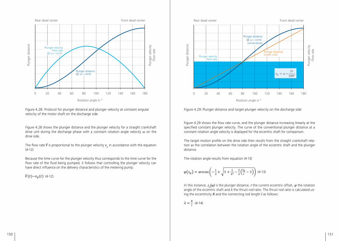
150 151
0 20 60 8040 100 120 140 160 180
Plunger velocityFlow rate
@ ω = const.
Plunger distance@ ω = const.
Rotation angle in °
Rear dead center Front dead center
Plun
ger
dist
ance
Plun
ger
velo
city
Fl
ow ra
te
Figure 4�28: Protocol for plunger distance and plunger velocity at constant angular veloci ty of the motor shaft on the discharge side
Figure 4�28 shows the plunger distance and the plunger velocity for a straight crankshaft drive unit during the discharge phase with a constant rotation angle velocity ω on the drive side�
The flow rate is proportional to the plunger velocity vp in accordance with the equation (4-12)�
Because the time curve for the plunger velocity thus corresponds to the time curve for the flow rate of the fluid being pumped, it follows that controlling the plunger velocity can have direct influence on the delivery characteristics of the metering pump�
(4-12)
0 20 60 8040 100 120 140 160 180
Plunger velocityFlow rate
Plunger distance@ ω = const.conventional
Plunger distancetarget curve
Rotation angle in °
Rear dead center Front dead center
Plun
ger
velo
city
Fl
ow ra
te
Plun
ger
dist
ance
Figure 4�29: Plunger distance and target plunger velocity on the discharge side
Figure 4�29 shows the flow rate curve, and the plunger distance increasing linearly at the specified constant plunger velocity� The curve of the conventional plunger distance at a constant rotation angle velocity is displayed for the eccentric shaft for comparison�
The target motion profile on the drive side then results from the straight crankshaft rela-tion as the correlation between the rotation angle of the eccentric shaft and the plunger distance�
The rotation angle results from equation (4-13)
(4-13)
In this instance, sp(φ) is the plunger distance, r the current eccentric offset, φ the rotation angle of the eccentric shaft and λ the thrust rod ratio� The thrust rod ratio is calculated us-ing the eccentricity R and the connecting rod length l as follows:
(4-14)
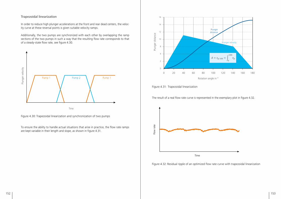
152 153
Trapezoidal linearization
In order to reduce high plunger accelerations at the front and rear dead centers, the veloc-ity curve at these reversal points is given suitable velocity ramps�
Additionally, the two pumps are synchronized with each other by overlapping the ramp sections of the two pumps in such a way that the resulting flow rate corresponds to that of a steady-state flow rate, see figure 4�30�
Time
Pump 1 Pump 1Pump 2
Plun
ger
velo
city
Figure 4�30: Trapezoidal linearization and synchronization of two pumps
To ensure the ability to handle actual situations that arise in practice, the flow rate ramps are kept variable in their length and slope, as shown in figure 4�31�
0
2
4
8
10
12
14
16
0 604020 10080 120 140 160 180
Plungerdistance
Plunger velocity
Rotation angle in °
Plun
ger
dist
ance
Figure 4�31: Trapezoidal linearization
The result of a real flow rate curve is represented in the exemplary plot in figure 4�32�
TimeFl
ow ra
teTime
Flow
rate
Figure 4�32: Residual ripple of an optimized flow rate curve with trapezoidal linearization
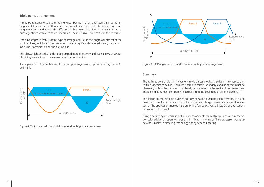
154 155
Triple pump arrangement
It may be reasonable to use three individual pumps in a synchronized triple pump ar-rangement to increase the flow rate� This principle corresponds to the double-pump ar-rangement described above� The difference is that here, an additional pump carries out a discharge stroke within the same time frame� The result is a 50% increase in the flow rate�
One advantageous feature of this type of arrangement lies in the length adjustment of the suction phase, which can now be carried out at a significantly reduced speed, thus reduc-ing plunger acceleration on the suction side�
This allows high-viscosity fluids to be pumped more effectively and even allows unfavora-ble piping installations to be overcome on the suction side�
A comparison of the double and triple pump arrangements is provided in figures 4�33 and 4�34�
φ = 360°, t = 1/n
Plun
ger
velo
city
Flow
rate
Pump 1 Pump 2
Rotation angleTime
Figure 4�33: Plunger velocity and flow rate, double pump arrangement
Plun
ger
velo
city
Flow
rate
φ = 360°, t = 1/n
Rotation angleTime
Pump 1 Pump 2 Pump 3
Figure 4�34: Plunger velocity and flow rate, triple pump arrangement
Summary
The ability to control plunger movement in wide areas provides a series of new approaches to fluid kinematics design� However, there are certain boundary conditions that must be observed, such as the maximum possible dynamics based on the inertia of the power train� These conditions must be taken into account from the beginning of system planning�
In addition to the example outlined for low-pulsation pumping characteristics, it is also possible to use fluid kinematics control to implement filling processes and micro flow me-tering� The applications named here are only a few select possibilities� Other applications are conceivable as well�
Using a defined synchronization of plunger movements for multiple pumps, also in interac-tion with additional system components in mixing, metering or filling processes, opens up new possibilities in metering technology and system engineering�
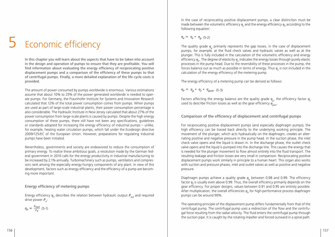
156 157
5 Economic efficiencyIn this chapter you will learn about the aspects that have to be taken into account in the design and operation of pumps to ensure that they are profitable. You will find information about evaluating the energy efficiency of reciprocating positive displacement pumps and a comparison of the efficiency of these pumps to that of centrifugal pumps. Finally, a more detailed explanation of the life cycle costs is provided.
The amount of power consumed by pumps worldwide is enormous� Various estimations assume that about 10% to 25% of the power generated worldwide is needed to oper-ate pumps� For Germany, the Fraunhofer Institute for Systems and Innovation Research calculated that 12% of the total power consumption comes from pumps� When pumps are used as part of large-scale industrial plants, their power consumption percentage is also considerable� The Hydraulic Institute in New Jersey calculated that about 27% of the power consumption from large-scale plants is caused by pumps� Despite the high energy consumption of these pumps, there still have not been any specifications, guidelines or standards adopted for increasing the energy efficiency of industrial pumps – unlike, for example, heating water circulation pumps, which fall under the Ecodesign directive 2009/125/EC of the European Union� However, preparations for regulating industrial pumps have been initiated�
Nevertheless, governments and society are endeavored to reduce the consumption of primary energy� To realize these ambitious goals, a resolution made by the German fed-eral government in 2010 calls for the energy productivity in industrial manufacturing to be increased by 2�1% annually� Turbomachinery such as pumps, ventilators and compres-sors rank among the especially energy-hungry components of any plant� In view of this development, factors such as energy efficiency and the efficiency of a pump are becom-ing more important�
Energy efficiency of metering pumps
Energy efficiency ηP describes the relation between hydraulic output Phyd and required drive power Pd :
(5-1)
In the case of reciprocating positive displacement pumps, a clear distinction must be made between the volumetric efficiency ηv and the energy efficiency ηP according to the following equation:
(5-2)
The quality grade ηg primarily represents the gap losses, in the case of displacement pumps, for example, at the fluid check valves and hydraulic valves as well as at the plunger� This is fully included in the calculation of the volumetric efficiency and energy efficiency ηP � The degree of elasticity ηe indicates the energy losses through purely elastic processes in the pump head� Due to the reversibility of these processes in the pump, the forces balance out as much as possible in terms of energy� Thus ηe is not included in the calculation of the energy efficiency of the metering pump�
The energy efficiency of a metering pump can be derived as follows:
(5-3)
Factors affecting the energy balance are the quality grade ηg , the efficiency factor ηf used to describe friction losses as well as the gear efficiency ηgear �
Comparison of the efficiency of displacement and centrifugal pumps
For reciprocating positive displacement pumps (and especially diaphragm pumps), the high efficiency can be traced back directly to the underlying working principle� The movement of the plunger, which acts hydraulically on the diaphragm, creates an alter-nating positive and negative pressure in the pump head� In the suction phase, the inlet check valve opens and the liquid is drawn in� In the discharge phase, the outlet check valve opens and the liquid is pumped into the discharge line� This causes the energy that is needed for the plunger movement to flow almost entirely into the fluid transport� The resulting leakage and friction losses are very small in comparison� Reciprocating positive displacement pumps work similarly in principle to a human heart� This organ also works with suction and pressure phases, inlet and outlet valves as well as positive and negative pressure�
Diaphragm pumps achieve a quality grade ηg between 0�98 and 0�99� The efficiency factor ηf is usually even above 0�99� Thus, the overall efficiency primarily depends on the gear efficiency� For proper designs, values between 0�91 and 0�95 are entirely possible� After multiplication, the overall efficiencies ηP for high-performance process diaphragm pumps can be around 90%�
The operating principle of the displacement pump differs fundamentally from that of the centrifugal pump� The centrifugal pump uses a redirection of the flow and the centrifu-gal force resulting from the radial velocity� The fluid enters the centrifugal pump through the suction pipe� It is caught by the rotating impeller and forced outward in a spiral path�
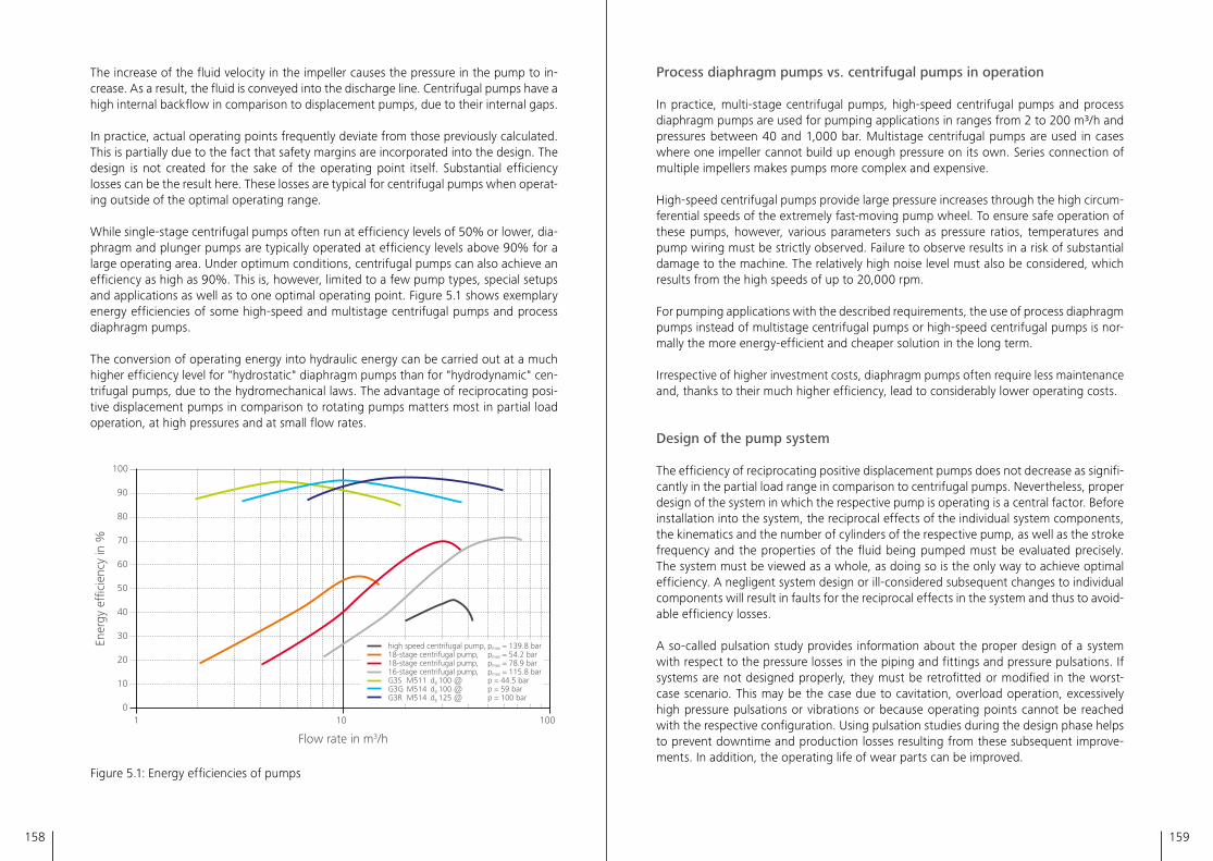
158 159
The increase of the fluid velocity in the impeller causes the pressure in the pump to in-crease� As a result, the fluid is conveyed into the discharge line� Centrifugal pumps have a high internal backflow in comparison to displacement pumps, due to their internal gaps�
In practice, actual operating points frequently deviate from those previously calculated� This is partially due to the fact that safety margins are incorporated into the design� The design is not created for the sake of the operating point itself� Substantial efficiency losses can be the result here� These losses are typical for centrifugal pumps when operat-ing outside of the optimal operating range�
While single-stage centrifugal pumps often run at efficiency levels of 50% or lower, dia-phragm and plunger pumps are typically operated at efficiency levels above 90% for a large operating area� Under optimum conditions, centrifugal pumps can also achieve an efficiency as high as 90%� This is, however, limited to a few pump types, special setups and applications as well as to one optimal operating point� Figure 5�1 shows exemplary energy efficiencies of some high-speed and multistage centrifugal pumps and process diaphragm pumps�
The conversion of operating energy into hydraulic energy can be carried out at a much higher efficiency level for "hydrostatic" diaphragm pumps than for "hydrodynamic" cen-trifugal pumps, due to the hydromechanical laws� The advantage of reciprocating posi-tive displacement pumps in comparison to rotating pumps matters most in partial load operation, at high pressures and at small flow rates�
100
90
80
70
60
50
40
30
20
10
1 10 1000
high speed centrifugal pump, pmax = 139.8 bar18-stage centrifugal pump, pmax = 54.2 bar18-stage centrifugal pump, pmax = 78.9 bar16-stage centrifugal pump, pmax = 115.8 barG3S M511 dp 100 @ p = 44.5 barG3G M514 dp 100 @ p = 59 barG3R M514 dp 125 @ p = 100 bar
Flow rate in m3/h
Ener
gy e
�ci
ency
in %
Figure 5�1: Energy efficiencies of pumps
Process diaphragm pumps vs. centrifugal pumps in operation
In practice, multi-stage centrifugal pumps, high-speed centrifugal pumps and process diaphragm pumps are used for pumping applications in ranges from 2 to 200 m3/h and pressures between 40 and 1,000 bar� Multistage centrifugal pumps are used in cases where one impeller cannot build up enough pressure on its own� Series connection of multiple impellers makes pumps more complex and expensive�
High-speed centrifugal pumps provide large pressure increases through the high circum-ferential speeds of the extremely fast-moving pump wheel� To ensure safe operation of these pumps, however, various parameters such as pressure ratios, temperatures and pump wiring must be strictly observed� Failure to observe results in a risk of substantial damage to the machine� The relatively high noise level must also be considered, which results from the high speeds of up to 20,000 rpm�
For pumping applications with the described requirements, the use of process diaphragm pumps instead of multistage centrifugal pumps or high-speed centrifugal pumps is nor-mally the more energy-efficient and cheaper solution in the long term�
Irrespective of higher investment costs, diaphragm pumps often require less maintenance and, thanks to their much higher efficiency, lead to considerably lower operating costs�
Design of the pump system
The efficiency of reciprocating positive displacement pumps does not decrease as signifi-cantly in the partial load range in comparison to centrifugal pumps� Nevertheless, proper design of the system in which the respective pump is operating is a central factor� Before installation into the system, the reciprocal effects of the individual system components, the kinematics and the number of cylinders of the respective pump, as well as the stroke frequency and the properties of the fluid being pumped must be evaluated precisely� The system must be viewed as a whole, as doing so is the only way to achieve optimal efficiency� A negligent system design or ill-considered subsequent changes to individual components will result in faults for the reciprocal effects in the system and thus to avoid-able efficiency losses�
A so-called pulsation study provides information about the proper design of a system with respect to the pressure losses in the piping and fittings and pressure pulsations� If systems are not designed properly, they must be retrofitted or modified in the worst-case scenario� This may be the case due to cavitation, overload operation, excessively high pressure pulsations or vibrations or because operating points cannot be reached with the respective configuration� Using pulsation studies during the design phase helps to prevent downtime and production losses resulting from these subsequent improve-ments� In addition, the operating life of wear parts can be improved�
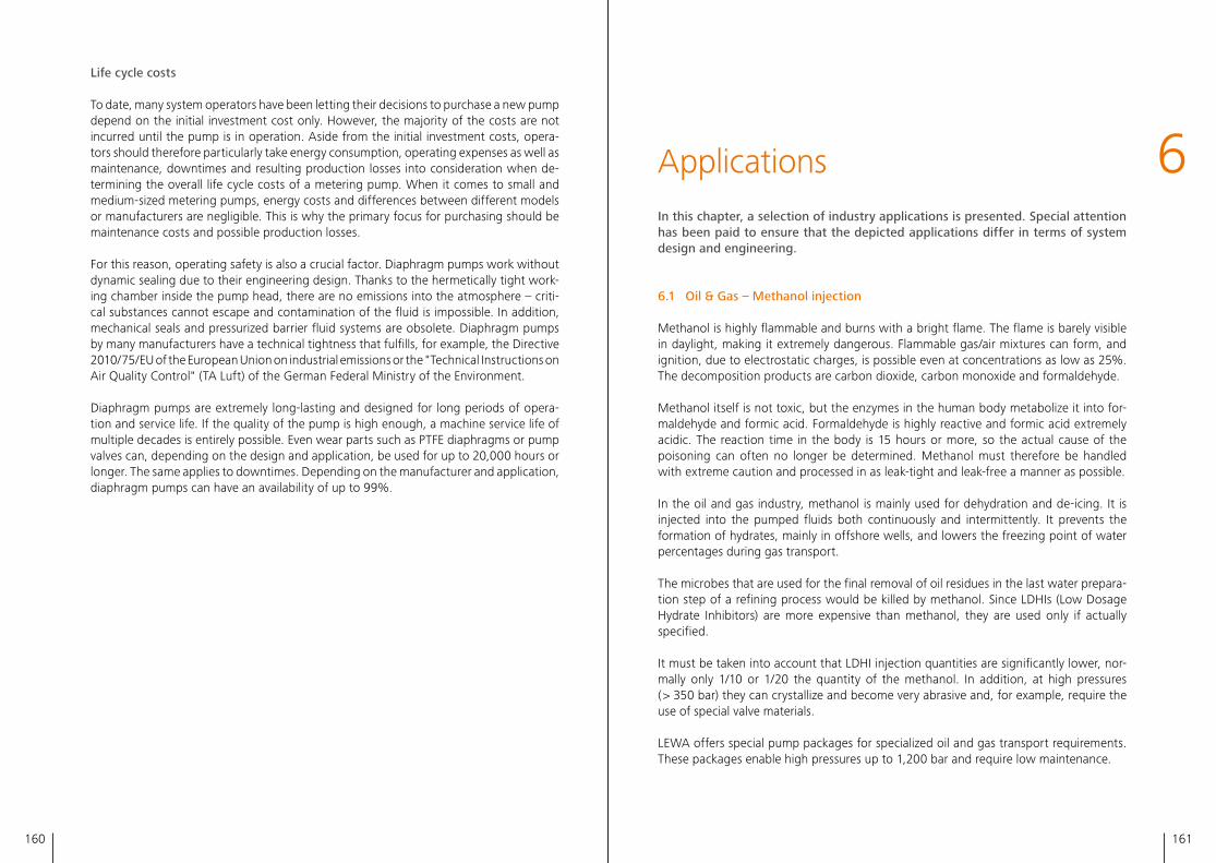
161160
Life cycle costs
To date, many system operators have been letting their decisions to purchase a new pump depend on the initial investment cost only. However, the majority of the costs are not incurred until the pump is in operation. Aside from the initial investment costs, opera-tors should therefore particularly take energy consumption, operating expenses as well as maintenance, downtimes and resulting production losses into consideration when de-termining the overall life cycle costs of a metering pump. When it comes to small and medium-sized metering pumps, energy costs and differences between different models or manufacturers are negligible. This is why the primary focus for purchasing should be maintenance costs and possible production losses.
For this reason, operating safety is also a crucial factor. Diaphragm pumps work without dynamic sealing due to their engineering design. Thanks to the hermetically tight work-ing chamber inside the pump head, there are no emissions into the atmosphere – criti-cal substances cannot escape and contamination of the fluid is impossible. In addition, mechanical seals and pressurized barrier fluid systems are obsolete. Diaphragm pumps by many manufacturers have a technical tightness that fulfills, for example, the Directive 2010/75/EU of the European Union on industrial emissions or the "Technical Instructions on Air Quality Control" (TA Luft) of the German Federal Ministry of the Environment.
Diaphragm pumps are extremely long-lasting and designed for long periods of opera-tion and service life. If the quality of the pump is high enough, a machine service life of multiple decades is entirely possible. Even wear parts such as PTFE diaphragms or pump valves can, depending on the design and application, be used for up to 20,000 hours or longer. The same applies to downtimes. Depending on the manufacturer and application, diaphragm pumps can have an availability of up to 99%.
6ApplicationsIn this chapter, a selection of industry applications is presented. Special attention has been paid to ensure that the depicted applications differ in terms of system design and engineering.
6.1 Oil & Gas – Methanol injection
Methanol is highly flammable and burns with a bright flame. The flame is barely visible in daylight, making it extremely dangerous. Flammable gas/air mixtures can form, and ignition, due to electrostatic charges, is possible even at concentrations as low as 25%. The decomposition products are carbon dioxide, carbon monoxide and formaldehyde.
Methanol itself is not toxic, but the enzymes in the human body metabolize it into for-maldehyde and formic acid. Formaldehyde is highly reactive and formic acid extremely acidic. The reaction time in the body is 15 hours or more, so the actual cause of the poisoning can often no longer be determined. Methanol must therefore be handled with extreme caution and processed in as leak-tight and leak-free a manner as possible.
In the oil and gas industry, methanol is mainly used for dehydration and de-icing. It is injected into the pumped fluids both continuously and intermittently. It prevents the formation of hydrates, mainly in offshore wells, and lowers the freezing point of water percentages during gas transport.
The microbes that are used for the final removal of oil residues in the last water prepara-tion step of a refining process would be killed by methanol. Since LDHIs (Low Dosage Hydrate Inhibitors) are more expensive than methanol, they are used only if actually specified.
It must be taken into account that LDHI injection quantities are significantly lower, nor-mally only 1/10 or 1/20 the quantity of the methanol. In addition, at high pressures ( > 350 bar) they can crystallize and become very abrasive and, for example, require the use of special valve materials.
LEWA offers special pump packages for specialized oil and gas transport requirements. These packages enable high pressures up to 1,200 bar and require low maintenance.
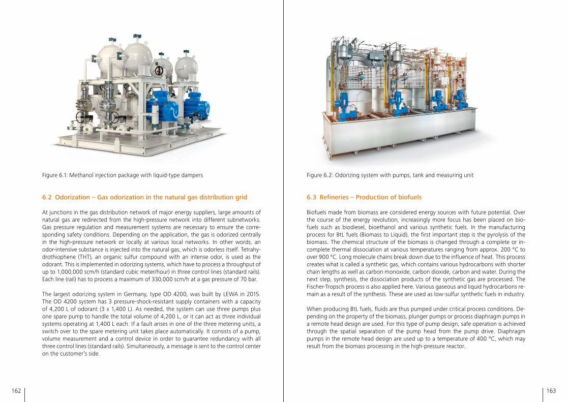
163162
Figure 6�2: Odorizing system with pumps, tank and measuring unit
6.3 Refineries – Production of biofuels
Biofuels made from biomass are considered energy sources with future potential� Over the course of the energy revolution, increasingly more focus has been placed on bio-fuels such as biodiesel, bioethanol and various synthetic fuels� In the manufacturing process for BtL fuels (Biomass to Liquid), the first important step is the pyrolysis of the biomass� The chemical structure of the biomass is changed through a complete or in-complete thermal dissociation at various temperatures ranging from approx� 200 °C to over 900 °C� Long molecule chains break down due to the influence of heat� This process creates what is called a synthetic gas, which contains various hydrocarbons with shorter chain lengths as well as carbon monoxide, carbon dioxide, carbon and water� During the next step, synthesis, the dissociation products of the synthetic gas are processed� The Fischer-Tropsch process is also applied here� Various gaseous and liquid hydrocarbons re-main as a result of the synthesis� These are used as low-sulfur synthetic fuels in industry�
When producing BtL fuels, fluids are thus pumped under critical process conditions� De-pending on the property of the biomass, plunger pumps or process diaphragm pumps in a remote head design are used� For this type of pump design, safe operation is achieved through the spatial separation of the pump head from the pump drive� Diaphragm pumps in the remote head design are used up to a temperature of 400 °C, which may result from the biomass processing in the high-pressure reactor�
Figure 6�1: Methanol injection package with liquid-type dampers
6.2 Odorization – Gas odorization in the natural gas distribution grid
At junctions in the gas distribution network of major energy suppliers, large amounts of natural gas are redirected from the high-pressure network into different subnetworks� Gas pressure regulation and measurement systems are necessary to ensure the corre-sponding safety conditions� Depending on the application, the gas is odorized centrally in the high-pressure network or locally at various local networks� In other words, an odor-intensive substance is injected into the natural gas, which is odorless itself� Tetrahy-drothiophene (THT), an organic sulfur compound with an intense odor, is used as the odorant� This is implemented in odorizing systems, which have to process a throughput of up to 1,000,000 scm/h (standard cubic meter/hour) in three control lines (standard rails)� Each line (rail) has to process a maximum of 330,000 scm/h at a gas pressure of 70 bar�
The largest odorizing system in Germany, type OD 4200, was built by LEWA in 2015� The OD 4200 system has 3 pressure-shock-resistant supply containers with a capacity of 4,200 L of odorant (3 x 1,400 L)� As needed, the system can use three pumps plus one spare pump to handle the total volume of 4,200 L, or it can act as three individual systems operating at 1,400 L each� If a fault arises in one of the three metering units, a switch over to the spare metering unit takes place automatically� It consists of a pump, volume measurement and a control device in order to guarantee redundancy with all three control lines (standard rails)� Simultaneously, a message is sent to the control center on the customer’s side�
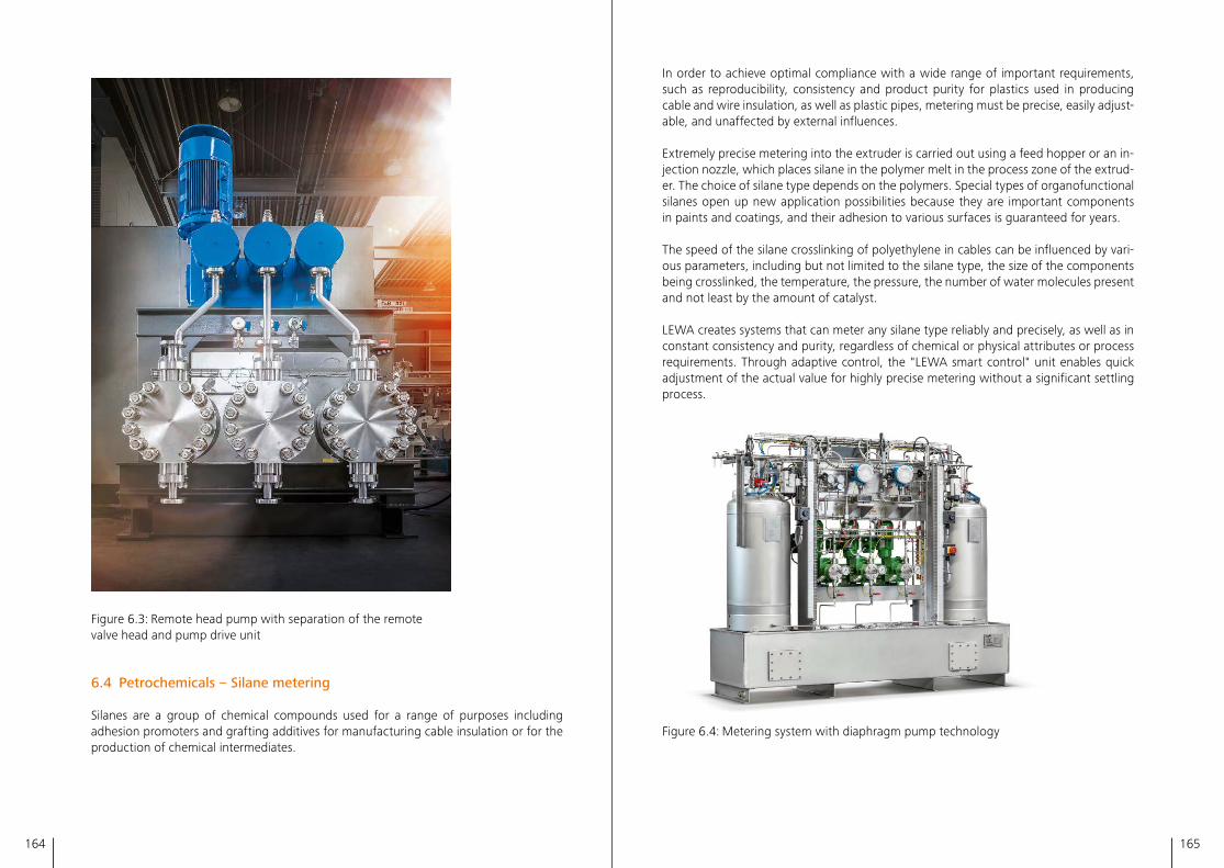
164 165
In order to achieve optimal compliance with a wide range of important requirements, such as reproducibility, consistency and product purity for plastics used in producing cable and wire insulation, as well as plastic pipes, metering must be precise, easily adjust-able, and unaffected by external influences�
Extremely precise metering into the extruder is carried out using a feed hopper or an in-jection nozzle, which places silane in the polymer melt in the process zone of the extrud-er� The choice of silane type depends on the polymers� Special types of organofunctional silanes open up new application possibilities because they are important components in paints and coatings, and their adhesion to various surfaces is guaranteed for years�
The speed of the silane crosslinking of polyethylene in cables can be influenced by vari-ous parameters, including but not limited to the silane type, the size of the components being crosslinked, the temperature, the pressure, the number of water molecules present and not least by the amount of catalyst�
LEWA creates systems that can meter any silane type reliably and precisely, as well as in constant consistency and purity, regardless of chemical or physical attributes or process requirements� Through adaptive control, the "LEWA smart control" unit enables quick adjustment of the actual value for highly precise metering without a significant settling process�
Figure 6�4: Metering system with diaphragm pump technology
Figure 6�3: Remote head pump with separation of the remote valve head and pump drive unit
6.4 Petrochemicals – Silane metering
Silanes are a group of chemical compounds used for a range of purposes including adhesion promoters and grafting additives for manufacturing cable insulation or for the production of chemical intermediates�
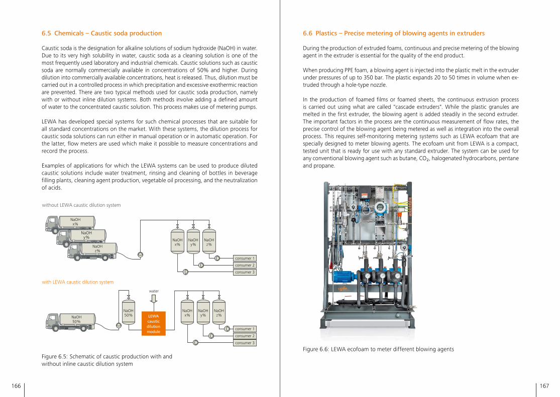
166 167
6.6 Plastics – Precise metering of blowing agents in extruders
During the production of extruded foams, continuous and precise metering of the blowing agent in the extruder is essential for the quality of the end product�
When producing PPE foam, a blowing agent is injected into the plastic melt in the extruder under pressures of up to 350 bar� The plastic expands 20 to 50 times in volume when ex-truded through a hole-type nozzle�
In the production of foamed films or foamed sheets, the continuous extrusion process is carried out using what are called "cascade extruders"� While the plastic granules are melted in the first extruder, the blowing agent is added steadily in the second extruder� The important factors in the process are the continuous measurement of flow rates, the precise control of the blowing agent being metered as well as integration into the overall process� This requires self-monitoring metering systems such as LEWA ecofoam that are specially designed to meter blowing agents� The ecofoam unit from LEWA is a compact, tested unit that is ready for use with any standard extruder� The system can be used for any conventional blowing agent such as butane, CO₂, halogenated hydrocarbons, pentane and propane�
Figure 6�6: LEWA ecofoam to meter different blowing agents
6.5 Chemicals – Caustic soda production
Caustic soda is the designation for alkaline solutions of sodium hydroxide (NaOH) in water� Due to its very high solubility in water, caustic soda as a cleaning solution is one of the most frequently used laboratory and industrial chemicals� Caustic solutions such as caustic soda are normally commercially available in concentrations of 50% and higher� During dilution into commercially available concentrations, heat is released� Thus, dilution must be carried out in a controlled process in which precipitation and excessive exothermic reaction are prevented� There are two typical methods used for caustic soda production, namely with or without inline dilution systems� Both methods involve adding a defined amount of water to the concentrated caustic solution� This process makes use of metering pumps�
LEWA has developed special systems for such chemical processes that are suitable for all standard concentrations on the market� With these systems, the dilution process for caustic soda solutions can run either in manual operation or in automatic operation� For the latter, flow meters are used which make it possible to measure concentrations and record the process�
Examples of applications for which the LEWA systems can be used to produce diluted caustic solutions include water treatment, rinsing and cleaning of bottles in beverage filling plants, cleaning agent production, vegetable oil processing, and the neutralization of acids�
without LEWA caustic dilution system
with LEWA caustic dilution system
consumer 3
consumer 2
consumer 1
consumer 3
consumer 2
consumer 1
LEWAcausticdilutionmodule
NaOH50 %NaOH
50 %
NaOHx %
NaOHy %
NaOHz %
NaOHx %
NaOHy %
NaOHz %
NaOHx %
NaOHy %
NaOHz %
water
Figure 6�5: Schematic of caustic production with and without inline caustic dilution system
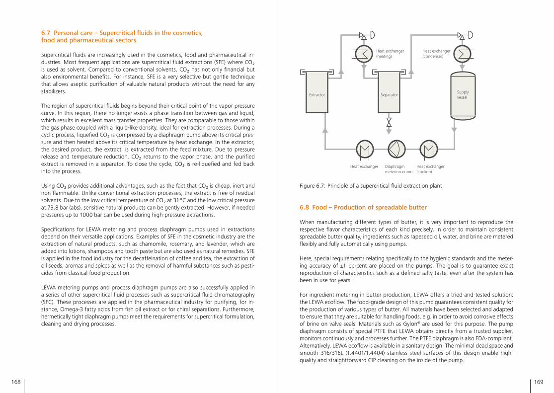
168 169
Diaphragm metering pump
Heat exchanger
SeparatorExtractorSupply vessel
Heat exchanger(cooling)
Heat exchanger (condenser)
Heat exchanger (heating)
Figure 6�7: Principle of a supercritical fluid extraction plant
6.8 Food – Production of spreadable butter
When manufacturing different types of butter, it is very important to reproduce the respective flavor characteristics of each kind precisely� In order to maintain consistent spreadable butter quality, ingredients such as rapeseed oil, water, and brine are metered flexibly and fully automatically using pumps�
Here, special requirements relating specifically to the hygienic standards and the meter-ing accuracy of ±1 percent are placed on the pumps� The goal is to guarantee exact reproduction of characteristics such as a defined salty taste, even after the system has been in use for years�
For ingredient metering in butter production, LEWA offers a tried-and-tested solution: the LEWA ecoflow� The food-grade design of this pump guarantees consistent quality for the production of various types of butter� All materials have been selected and adapted to ensure that they are suitable for handling foods, e�g� in order to avoid corrosive effects of brine on valve seals� Materials such as Gylon® are used for this purpose� The pump diaphragm consists of special PTFE that LEWA obtains directly from a trusted supplier, monitors continuously and processes further� The PTFE diaphragm is also FDA-compliant� Alternatively, LEWA ecoflow is available in a sanitary design� The minimal dead space and smooth 316/316L (1�4401/1�4404) stainless steel surfaces of this design enable high-quality and straightforward CIP cleaning on the inside of the pump�
6.7 Personal care – Supercritical fluids in the cosmetics, food and pharmaceutical sectors
Supercritical fluids are increasingly used in the cosmetics, food and pharmaceutical in-dustries� Most frequent applications are supercritical fluid extractions (SFE) where CO₂ is used as solvent� Compared to conventional solvents, CO₂ has not only financial but also environmental benefits� For instance, SFE is a very selective but gentle technique that allows aseptic purification of valuable natural products without the need for any stabilizers�
The region of supercritical fluids begins beyond their critical point of the vapor pressure curve� In this region, there no longer exists a phase transition between gas and liquid, which results in excellent mass transfer properties� They are comparable to those within the gas phase coupled with a liquid-like density, ideal for extraction processes� During a cyclic process, liquefied CO₂ is compressed by a diaphragm pump above its critical pres-sure and then heated above its critical temperature by heat exchange� In the extractor, the desired product, the extract, is extracted from the feed mixture� Due to pressure release and temperature reduction, CO₂ returns to the vapor phase, and the purified extract is removed in a separator� To close the cycle, CO₂ is re-liquefied and fed back into the process�
Using CO₂ provides additional advantages, such as the fact that CO₂ is cheap, inert and non-flammable� Unlike conventional extraction processes, the extract is free of residual solvents� Due to the low critical temperature of CO₂ at 31 °C and the low critical pressure at 73�8 bar (abs), sensitive natural products can be gently extracted� However, if needed pressures up to 1000 bar can be used during high-pressure extractions�
Specifications for LEWA metering and process diaphragm pumps used in extractions depend on their versatile applications� Examples of SFE in the cosmetic industry are the extraction of natural products, such as chamomile, rosemary, and lavender, which are added into lotions, shampoos and tooth paste but are also used as natural remedies� SFE is applied in the food industry for the decaffeination of coffee and tea, the extraction of oil seeds, aromas and spices as well as the removal of harmful substances such as pesti-cides from classical food production�
LEWA metering pumps and process diaphragm pumps are also successfully applied in a series of other supercritical fluid processes such as supercritical fluid chromatography (SFC)� These processes are applied in the pharmaceutical industry for purifying, for in-stance, Omega-3 fatty acids from fish oil extract or for chiral separations� Furthermore, hermetically tight diaphragm pumps meet the requirements for supercritical formulation, cleaning and drying processes�
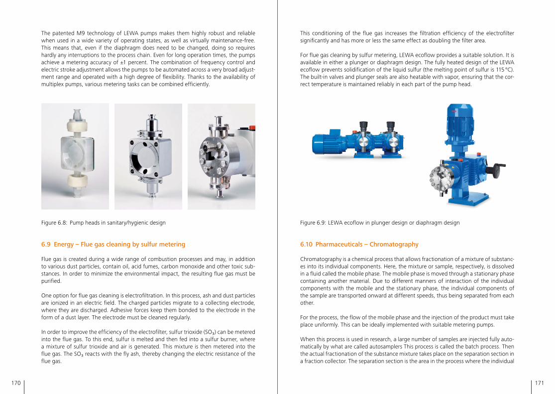
170 171
This conditioning of the flue gas increases the filtration efficiency of the electrofilter significantly and has more or less the same effect as doubling the filter area� For flue gas cleaning by sulfur metering, LEWA ecoflow provides a suitable solution� It is available in either a plunger or diaphragm design� The fully heated design of the LEWA ecoflow prevents solidification of the liquid sulfur (the melting point of sulfur is 115 °C)� The built-in valves and plunger seals are also heatable with vapor, ensuring that the cor-rect temperature is maintained reliably in each part of the pump head�
Figure 6�9: LEWA ecoflow in plunger design or diaphragm design
6.10 Pharmaceuticals – Chromatography
Chromatography is a chemical process that allows fractionation of a mixture of substanc-es into its individual components� Here, the mixture or sample, respectively, is dissolved in a fluid called the mobile phase� The mobile phase is moved through a stationary phase containing another material� Due to different manners of interaction of the individual components with the mobile and the stationary phase, the individual components of the sample are transported onward at different speeds, thus being separated from each other�
For the process, the flow of the mobile phase and the injection of the product must take place uniformly� This can be ideally implemented with suitable metering pumps�
When this process is used in research, a large number of samples are injected fully auto-matically by what are called autosamplers This process is called the batch process� Then the actual fractionation of the substance mixture takes place on the separation section in a fraction collector� The separation section is the area in the process where the individual
The patented M9 technology of LEWA pumps makes them highly robust and reliable when used in a wide variety of operating states, as well as virtually maintenance-free� This means that, even if the diaphragm does need to be changed, doing so requires hardly any interruptions to the process chain� Even for long operation times, the pumps achieve a metering accuracy of ±1 percent� The combination of frequency control and electric stroke adjustment allows the pumps to be automated across a very broad adjust-ment range and operated with a high degree of flexibility� Thanks to the availability of multiplex pumps, various metering tasks can be combined efficiently�
Figure 6�8: Pump heads in sanitary/hygienic design
6.9 Energy – Flue gas cleaning by sulfur metering
Flue gas is created during a wide range of combustion processes and may, in addition to various dust particles, contain oil, acid fumes, carbon monoxide and other toxic sub-stances� In order to minimize the environmental impact, the resulting flue gas must be purified�
One option for flue gas cleaning is electrofiltration� In this process, ash and dust particles are ionized in an electric field� The charged particles migrate to a collecting electrode, where they are discharged� Adhesive forces keep them bonded to the electrode in the form of a dust layer� The electrode must be cleaned regularly�
In order to improve the efficiency of the electrofilter, sulfur trioxide (SO₃) can be metered into the flue gas� To this end, sulfur is melted and then fed into a sulfur burner, where a mixture of sulfur trioxide and air is generated� This mixture is then metered into the flue gas� The SO₃ reacts with the fly ash, thereby changing the electric resistance of the flue gas�
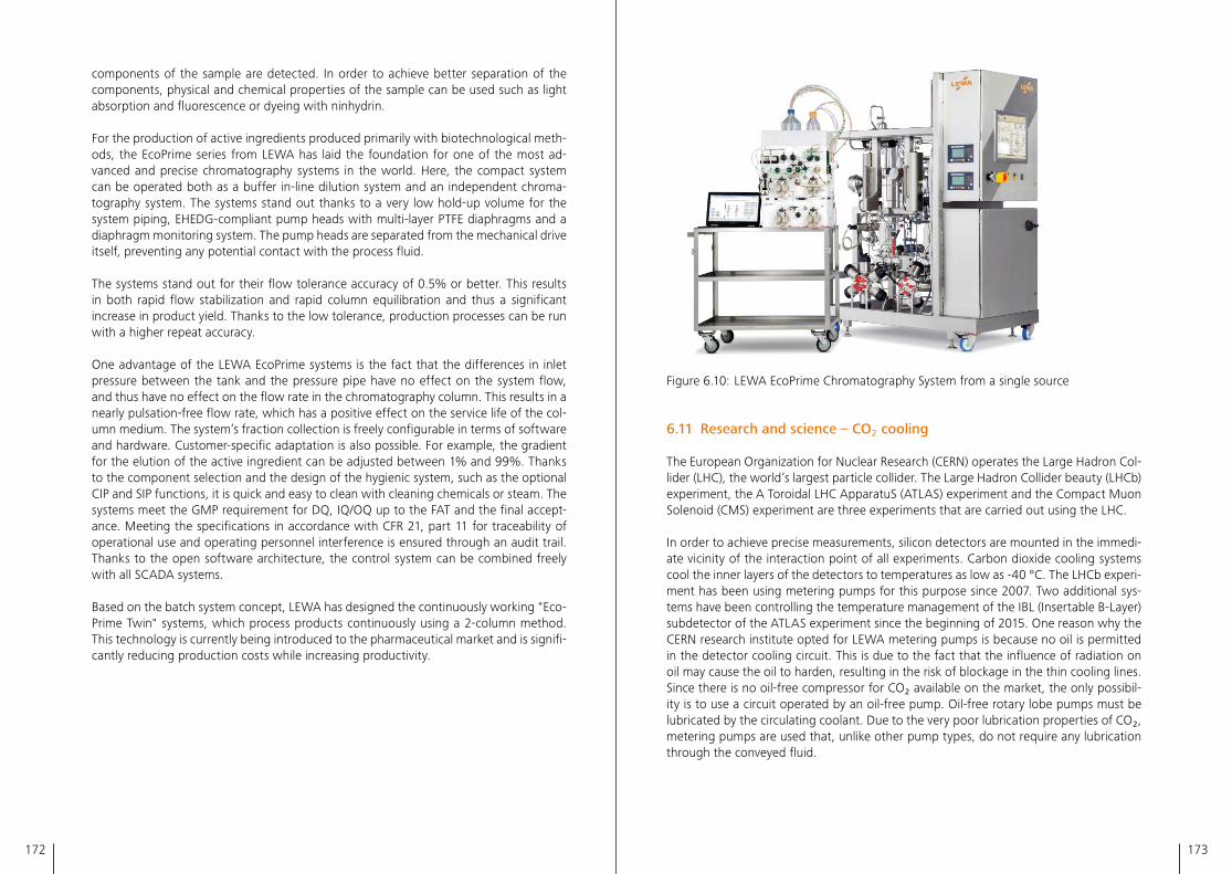
172 173
Figure 6�10: LEWA EcoPrime Chromatography System from a single source
6.11 Research and science – CO₂ cooling
The European Organization for Nuclear Research (CERN) operates the Large Hadron Col-lider (LHC), the world’s largest particle collider� The Large Hadron Collider beauty (LHCb) experiment, the A Toroidal LHC ApparatuS (ATLAS) experiment and the Compact Muon Solenoid (CMS) experiment are three experiments that are carried out using the LHC�
In order to achieve precise measurements, silicon detectors are mounted in the immedi-ate vicinity of the interaction point of all experiments� Carbon dioxide cooling systems cool the inner layers of the detectors to temperatures as low as -40 °C� The LHCb experi-ment has been using metering pumps for this purpose since 2007� Two additional sys-tems have been controlling the temperature management of the IBL (Insertable B-Layer) subdetector of the ATLAS experiment since the beginning of 2015� One reason why the CERN research institute opted for LEWA metering pumps is because no oil is permitted in the detector cooling circuit� This is due to the fact that the influence of radiation on oil may cause the oil to harden, resulting in the risk of blockage in the thin cooling lines� Since there is no oil-free compressor for CO₂ available on the market, the only possibil-ity is to use a circuit operated by an oil-free pump� Oil-free rotary lobe pumps must be lubricated by the circulating coolant� Due to the very poor lubrication properties of CO₂, metering pumps are used that, unlike other pump types, do not require any lubrication through the conveyed fluid�
components of the sample are detected� In order to achieve better separation of the components, physical and chemical properties of the sample can be used such as light absorption and fluorescence or dyeing with ninhydrin�
For the production of active ingredients produced primarily with biotechnological meth-ods, the EcoPrime series from LEWA has laid the foundation for one of the most ad-vanced and precise chromatography systems in the world� Here, the compact system can be operated both as a buffer in-line dilution system and an independent chroma-tography system� The systems stand out thanks to a very low hold-up volume for the system piping, EHEDG-compliant pump heads with multi-layer PTFE diaphragms and a diaphragm monitoring system� The pump heads are separated from the mechanical drive itself, preventing any potential contact with the process fluid�
The systems stand out for their flow tolerance accuracy of 0�5% or better� This results in both rapid flow stabilization and rapid column equilibration and thus a significant increase in product yield� Thanks to the low tolerance, production processes can be run with a higher repeat accuracy�
One advantage of the LEWA EcoPrime systems is the fact that the differences in inlet pressure between the tank and the pressure pipe have no effect on the system flow, and thus have no effect on the flow rate in the chromatography column� This results in a nearly pulsation-free flow rate, which has a positive effect on the service life of the col-umn medium� The system’s fraction collection is freely configurable in terms of software and hardware� Customer-specific adaptation is also possible� For example, the gradient for the elution of the active ingredient can be adjusted between 1% and 99%� Thanks to the component selection and the design of the hygienic system, such as the optional CIP and SIP functions, it is quick and easy to clean with cleaning chemicals or steam� The systems meet the GMP requirement for DQ, IQ/OQ up to the FAT and the final accept-ance� Meeting the specifications in accordance with CFR 21, part 11 for traceability of operational use and operating personnel interference is ensured through an audit trail� Thanks to the open software architecture, the control system can be combined freely with all SCADA systems�
Based on the batch system concept, LEWA has designed the continuously working "Eco-Prime Twin" systems, which process products continuously using a 2-column method� This technology is currently being introduced to the pharmaceutical market and is signifi-cantly reducing production costs while increasing productivity�
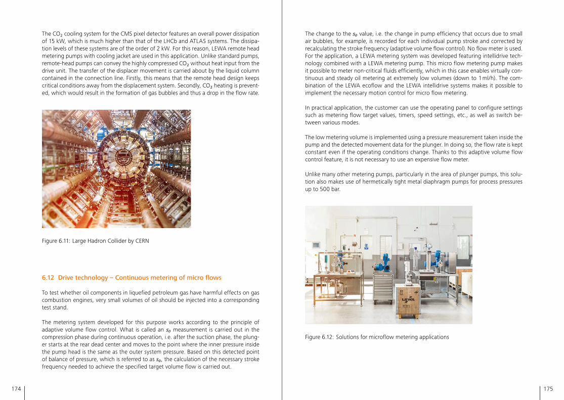
174 175
The change to the s₀ value, i�e� the change in pump efficiency that occurs due to small air bubbles, for example, is recorded for each individual pump stroke and corrected by recalculating the stroke frequency (adaptive volume flow control)� No flow meter is used�For the application, a LEWA metering system was developed featuring intellidrive tech-nology combined with a LEWA metering pump� This micro flow metering pump makes it possible to meter non-critical fluids efficiently, which in this case enables virtually con-tinuous and steady oil metering at extremely low volumes (down to 1 ml/h)� The com-bination of the LEWA ecoflow and the LEWA intellidrive systems makes it possible to implement the necessary motion control for micro flow metering�
In practical application, the customer can use the operating panel to configure settings such as metering flow target values, timers, speed settings, etc�, as well as switch be-tween various modes�
The low metering volume is implemented using a pressure measurement taken inside the pump and the detected movement data for the plunger� In doing so, the flow rate is kept constant even if the operating conditions change� Thanks to this adaptive volume flow control feature, it is not necessary to use an expensive flow meter�
Unlike many other metering pumps, particularly in the area of plunger pumps, this solu-tion also makes use of hermetically tight metal diaphragm pumps for process pressures up to 500 bar�
Figure 6�12: Solutions for microflow metering applications
The CO₂ cooling system for the CMS pixel detector features an overall power dissipation of 15 kW, which is much higher than that of the LHCb and ATLAS systems� The dissipa-tion levels of these systems are of the order of 2 kW� For this reason, LEWA remote head metering pumps with cooling jacket are used in this application� Unlike standard pumps, remote-head pumps can convey the highly compressed CO₂ without heat input from the drive unit� The transfer of the displacer movement is carried about by the liquid column contained in the connection line� Firstly, this means that the remote head design keeps critical conditions away from the displacement system� Secondly, CO₂ heating is prevent-ed, which would result in the formation of gas bubbles and thus a drop in the flow rate�
Figure 6�11: Large Hadron Collider by CERN
6.12 Drive technology – Continuous metering of micro flows
To test whether oil components in liquefied petroleum gas have harmful effects on gas combustion engines, very small volumes of oil should be injected into a corresponding test stand�
The metering system developed for this purpose works according to the principle of adaptive volume flow control� What is called an s₀ measurement is carried out in the compression phase during continuous operation, i�e� after the suction phase, the plung-er starts at the rear dead center and moves to the point where the inner pressure inside the pump head is the same as the outer system pressure� Based on this detected point of balance of pressure, which is referred to as s₀, the calculation of the necessary stroke frequency needed to achieve the specified target volume flow is carried out�
176 177
American Petroleum Institute APIThe American Petroleum Institute is a national trade association representing all aspects of America's oil and natural gas industry�
Biomass to Liquid BtLBiomass liquefaction� Process for manufactur-ing synthetic fuels from biomass�
Bubble point pressureComparable to the vapor pressure� Tem-perature, at a given pressure, where the first bubble of gas is formed when heating a liquid mixture� Also used when dissolved gas starts to outgas from the liquid�
Canadian Electrical Code CECStandard of the Canadian Standards Associa-tion defining the installation and maintenance of electric equipment�
CavitationVaporization of a fluid if the pressure in the system at a single point is less than the vapor pressure of the fluid� Conversely, after the vaporization process, the tiny gas bubbles implode when the pressure rises again� Upon implosion, micro-jets are formed� Their peak momentums are high enough to render sur-faces in the affected area, and thus materials, porous and permanently damaged�
ChromatographyIn chemistry, chromatography refers to a process that allows a mixture of substances to be separated through differential partition-ing of its individual components in a mobile phase traveling through a stationary phase� Chromatography is used in organic chemistry, inorganic chemistry, and the pharmaceutical, biochemistry, biotechnology, microbiology, food chemistry and environmental chemistry industries�
Cleaning in Place CIPRefers to a process for cleaning a system or complete production unit (e�g� process-engi-neering systems, pharmaceutical or biological production systems) without disassembly, being "in place for production"� An approved CIP procedure is used for the cleaning of the equipment, referring to a specific contact time, pressure, flowrate, cleaning reagent or other process-relevant parameters�
Closing delayThe closing delay of a fluid valve is the gap between the points of time when the plunger reaches the dead center and the closing body shuts the valve� In case of highly viscous flu-ids, the closing body may reach the valve seat later than it should, which results in a loss of flow rate due to backflow�
Closing energyThe closing energy of the fluid valves is mainly the kinetic energy of the closing body when hitting the valve seat� So, it is defined by the mass, speed and differential pressure when the valve is closing� Depending on the specific amount of energy, this can lead to wear or deformation of closing body and valve seat�
Code of Federal Regulations CFRIn addition to the United States Code, the Code of Federal Regulations represents an important source of federal laws of the United States� While the United States Code usually contains only laws, the Code of Federal Regu-lations includes the administrative regulations enacted by federal agencies� For example, CFR 21 and the following parts deal with pharmaceutical production and their legal aspects�
Compressed Natural Gas CNGNatural gas (methane) stored at high pressure�
Glossary & Abbreviations
Condition Monitoring System CMSCondition monitoring systems identifying changes in monitored parameters in machin-ery in order to indicate upcoming faults and to predict when maintenance should be per-formed� The use is the possibility to schedule service intervals as and when required and therefore to prevent damages and break-downs�
Conseil Européen pour la Recherche Nucléaire CERNEuropean Organization for Nuclear Research�
Control push rod Spring-loaded valve spool that is used for diaphragm positioning by controlling the point of time for replenishing oil� It replaces the rear perforated disk in the diaphragm pump, as well�
Current Good Manufacturing Practice CGMPInspection methods and guidelines to ensure a controlled production under good and con-sistent, approved quality aspects used in the pharmaceutical industry� In an audit, authori-ties will check the current quality standard in the manufacturing area or site�
Dead center At plunger pumps, the dead centers are the front and the rear end points where the plunger's movement reverses�
Dead space The dead space is the volume that remains in the pressurized hydraulic and working chambers when the plunger and diaphragm reach the front dead center� The size of the dead space has a reciprocal influence on volumetric efficiency since this fluid volume is compressed and decompressed during each stroke and thus not contributing to the conveying function�
Degassing valveSee vent valve
Design Qualification DQThe equipment user certifies that the equip-ment has been designed correctly and built
to meet the specifications to follow GMP aspects and fulfills requirements� DQ starts during the planning phase for the equipment and includes documentation from the begin-ning to finalization of the unit�
DiaphragmThe diaphragm has various functions� It separates the working space and the hydraulic space and transfers the movement of the plunger to the conveyed fluid� Diaphragms are usually made from either plastic or metal�
Diaphragm positioning systemThe diaphragm positioning system brings the diaphragm into correct position before start up when the pump is still standing still� This is necessary if there is negative pressure on the suction side during standstill� Then the dia-phragm could move forward into an incorrect position due to leakage at the plunger seal�
Diaphragm support plateDiaphragm support plates are perforated disks installed in the hydraulic chamber and in the working chamber� They are used to sup-port the flexible diaphragm at the front dead center and at the rear dead center, preventing overstretching of the diaphragm�
Discharge sideOutput side of a pump�
DisplacerIn case of displacement pumps, this is the component which directly or indirectly sets the fluid in motion, and basically pushes and drags it to be pumped� Displacers can be spindles, eccentric screws, plungers, rotary plungers, gear wheels, rolling plungers, vanes, diaphragms, etc�
DissipationIrreversible process in which entropy is produced� Some of the "usable" energy is lost and released as heat�
Drive unit Unit between drive and pump head� In most cases it transforms the rotary motion of the drive into a reciprocating movement� This is often realized by a crank mechanism and a
178 179
reduction gear for reduced speed integrated in a single housing�
Electric stroke adjustmentDevice for adjusting the stroke of the plunger based on an electric drive�
Electromagnetic compatibility EMCElectromagnetic compatibility means that an electronic or electrical product or system shall work as intended in its environment� The product shall not generate electromagnetic emissions which may disturb or influence oth-er products, and it also shall be immune in the presence of electromagnetic environments� EMC is a branch of electrical engineering and deals with problems of conducted interfer-ences as well as radiated emissions�
Elution An extraction process in which one com-ponent is washed out from a material by means of a solvent or a mixture of solvents� In chromatography for example, the desired product is removed from the stationary phase by the eluent and collected further down in the process equipment�
Energy productivity Energy consumption in proportion to the gross domestic product (GDP)
European Hygienic Engineering and Design Group EHEDGEHEDG certification: Certification for hygienic machines, devices and components that are designed for cleaning with fluids�
Factory Acceptance Test FATThe factory acceptance test of a product at the manufacturer's facility to check whether the product complies with the customer’s order and specifications�
Fluid mechanics Study of the mechanics of fluids, consisting of two branches: fluid statics, which is the study of fluids at rest, and fluid dynamics, which is the study of forces acting on fluids in motion�
Fluid valveSee process valve
FluidsUmbrella term for media being pumped� Flu-ids may be liquids, gases, solid materials and mixtures of substances�
Foundation Fieldbus A fieldbus communication system common in the USA in the areas of production technol-ogy and automation�
Frequency inverter See VFD
Front dead center FDCFront end point where the plunger's move-ment reverses
Gas removal plunger The gas removal plunger is a part of a special design of a gas removal valve where the removed volume is controlled by this plunger�
Gas removal valveSee vent valve
Good Manufacturing Practice GMPSee also CGMP: Method used in many coun-tries to ensure that the current quality stand-ards in the manufacturing of pharmaceuticals, medicinal products, and cosmetics, as well as foods and animal feed, are under control�
High- stroke characteristicThe so-called high-stroke characteristic of a pressure relief valve describes the quick drop of pressure in the hydraulic chamber because of its design affecting a high lift of the closing body when opening�
High- stroke characteristic HARTCommunication protocol based on standard-ized analog 4-20 mA signaling�
Hydraulic chamber Space behind the diaphragm that contains the hydraulic fluid�
HydrodynamicsBranch of fluid mechanics which studies the movement of liquids� The name is derived from the Greek "hydros", since the most well-known fluid is water (hydros)�
Inlet pressure lossPressure loss inside the suction valve and the pump head, caused by the inflow of the fluid in the pump head during the suction stroke�
Installation Qualification IQ The instrument itself or parts of the unit is/are working according to the designed and planned specifications (during Design Qualifi-cation) to be suitable for the selected process task, e�g� a thermometer can read the right temperature range with the needed precision� During the IQ process it is verified that a cali-brated reference instrument is used�
Instrumentation and control engineering E/I&C Electrical/Instrumentation and control engineering: Measurement and control of process variables within a production process� Instrumentation and control engineering typi-cally involves collecting, preparing and further processing measured values in order to con-trol devices using the information obtained or to regulate systems and processes�
Large Hadron Collider LHCCERN's particle accelerator�
Leak replenishing valve Suction valve in the hydraulic part that opens to allow the leaked volume of oil to be replenished from the reservoir� It is also called "snifting valve"�
Liquefied GasA gas that has been liquefied by cooling and/or compression�
Liquefied Natural Gas LNGNatural gas liquefied by cooling to reduce volume for non-pressurized storage and transportation
Liquefied Petroleum Gas LPGHydrocarbon gases (variable mixture, primarily consisting of butane and propane) that have been liquefied by compression�
Low Dosage Hydrate Inhibitor LDHISubstance for preventing the formation of gas hydrates from water and small hydrocarbons
at increased pressure and low temperature� Hydrates may cause blockages in gas pipe-lines, for example� In order to prevent this, inhibitors are admixed to the transported gas� The LDHIs have a hydrate inhibiting effect even when used in low quantities�
Modbus remote terminal unit Modbus RTUModbus remote terminal unit� Tried-and-tested communication protocol for transmit-ting data between devices made by different manufacturers�
National Electrical Code NECA legal standard with validity in the USA that defines the safe installation of electrical con-nections and electrical equipment�
Net Positive Inlet Pressure NPIPNet pressure above vapor pressure� NPIP is specified in kPa, bar or psi�
Net Positive Inlet Pressure Available NPIPAAvailable net pressure (on the system side) at the inlet cross-section of the pump (recipro-cating positive displacement pumps)�
Net Positive Inlet Pressure Required NPIPRNet pressure at the inlet cross-section of the pump (reciprocating positive displacement pumps) required by the pump to run without cavitating�
Net Positive Suction Head NPSHNet positive suction head in accordance with DIN EN ISO 12723 or the minimum suction head above vapor pressure� The NPSH is specified in m or ft�
Net Positive Suction Head Available NPSHANet positive suction head at the inlet cross-section of the pump available on the system side�
Net Positive Suction Head Required NPSHRNet positive suction head required by the pump to run without cavitating�
180 181
Newtonian fluidA Newtonian fluid, named for Isaac Newton, has a linearly-viscous flow behavior, charac-terized by a viscosity that is load-independent� This means the viscosity is a pure material property and independent of both shear stress and shear rate� Thus, the fluids obey the Navier-Stokes equations� Water and air are examples of Newtonian fluids�
Operational Qualification OQInstrument or complete unit functions in ac-cordance with planned operational require-ments� For example, a pump delivers the right flow rate and pressure under the process conditions�
Particles from Gas Saturated Solutions PGSSHigh pressure process with supercritical CO₂ for the generation of particles
PID controllers PIDThe abbreviation PID stands for Proportional-Integral-Differential and denotes a type of controller in instrumentation and control engineering in which the three controller characteristics – proportional controller, inte-gral controller and differential controller – are combined with one another�
Polyphenyl ether PPEHigh-temperature resistant class of polymers, containing a phenoxy and/or thiophenoxy group as repeating unit�
Polytetrafluoroethylene PTFESemi-crystalline thermoplastic polymer made from fluorine and carbon, also referred to as Teflon� Thanks to its chemical inertness, it is often used for constructing diaphragms�
Positive Temperature Coefficient PTC PTCs are used to monitor the temperature in windings of electronic devices and can thus be used as overload protection� PTCs are semi-conductors and their function is based on the property of the material that its electrical resistance increases with rising temperature�
Pressure chamberWorking space of a plunger pump� In a dia-phragm pump, the diaphragm separates the pressure chamber in a working chamber and a hydraulic chamber�
Pressure relief valve PRVPressure actuated valve in the hydraulic part which opens at a defined pressure depend-ing on the maximum allowed pressure of the pump� It protects the pump from overload by releasing hydraulic oil from the hydraulic chamber to the reservoir�
Process Field Bus PROFIBUSStandard for fieldbus communication
Process pumpProcess pumps are used to feed processes in an industrial plant or installation, and are usu-ally pumps of high hydraulic power�
Process valveThe process valves or product valves are the two valves that separate the suction side and the discharge side of the working space of the pump from the fluid lines� Common designs include ball valves, plate valves and cone valves�
Profibus DP (decentralized peripheral equipment) DPA fieldbus communication system common throughout Europe in the areas of production technology and automation�
Programmable logic controller PLCIndustrial digital computer for the control of manufacturing processes
Pulsation damperEither liquid- or gas-filled vessel that dampens volume and pressure fluctuations in the piping system�
Pulsation suppression deviceAny installation that dampens volume and pressure fluctuations in the piping system, e�g� pulsation damper or orifice�
Pumping chamberSee working space�
Rear dead center RDCRear end point where the plunger's move-ment reverses
Recipe meteringMixing process in which various ingredients are mixed in different proportions� This can be conducted by a multi-head pump, with different pump head sizes, stroke lengths and/or stroke frequencies�
Remote valve head Pump head part of a remote head pump usu-ally containing the fluid valves� In some cases, the diaphragm is also included�
Removal plungerSee gas removal plunger
Safety Integrity Level SILIn the context of functional safety, the IEC 61508 and IEC 61511 standards, as well as other standards, describe a process for the determination of potential risks to persons, systems, devices and processes in the event of a malfunction� The SI levels 1 to 4 (SIL1 to SIL4) that originated from the standards specify the defined safety function in case of failure� Safety increases as SIL increases�
Site Acceptance Test SATTest of the equipment on site to validate the required performance under process condi-tions� Criteria and scope need to be agreed between supplier and purchaser�
Snifting valveSee leak replenishing valve
Sodium hydroxide NaOHCaustic soda is the designation for solutions of sodium hydroxide (NaOH) in water�
Standard cubic meter scmThe standard cubic meter is a unit of volume that is used for gases at defined standard con-ditions for pressure and temperature, usually at 1�013 bar and 15 °C� However, other defini-tions of standard conditions are also used, e�g� 1�013 bar and 0 °C, 1�0 bar and 20 °C or 1�016 bar and 15�6 °C (60 °F)�
Sterilization in Place/Steaming in Place SIPDenotes a cleaning procedure in process engineering systems, especially in pharma-ceutical and biological production systems, in which all product-contacting surfaces of the system are sterilized without any dismantling being necessary� For SIP in the pharmaceuti-cal industry saturated steam with a certain pressure and temperature is most often used to kill living organisms and spores�
Stroke adjustmentDevice for adjusting the stroke of the plunger�
Suction sideInlet side of the pump�
Supercritical fluid chromatography SFCSupercritical fluid chromatography, such as the separation and purification of compounds using e�g� carbon dioxide as a mobile phase�
Supercritical fluid extraction SFESupercritical fluid extraction for e�g� extrac-tion of plant ingredients, decaffeination and degreasing, typically with carbon dioxide�
Supercritical fluid reaction SFRChemical reaction taking place in a supercriti-cal fluid� Usually applied to replace organic solvents�
System control and data acquisition SCADAMonitoring and control of technical pro-cesses by means of control software, which is installed on a central control system in a network, to which other units are connected to get an overview of the complete produc-tion unit’s state and cycles� Another purpose is to collect dedicated data, to be logged on a central repository and to be put into a report file record to document the complete produc-tion data�
Tetrahydrothiophene THTAn organic sulfur compound with an intense odor, used as an odorant for natural gas�
Vapor pressurePressure at which the fluid begins to evaporate�
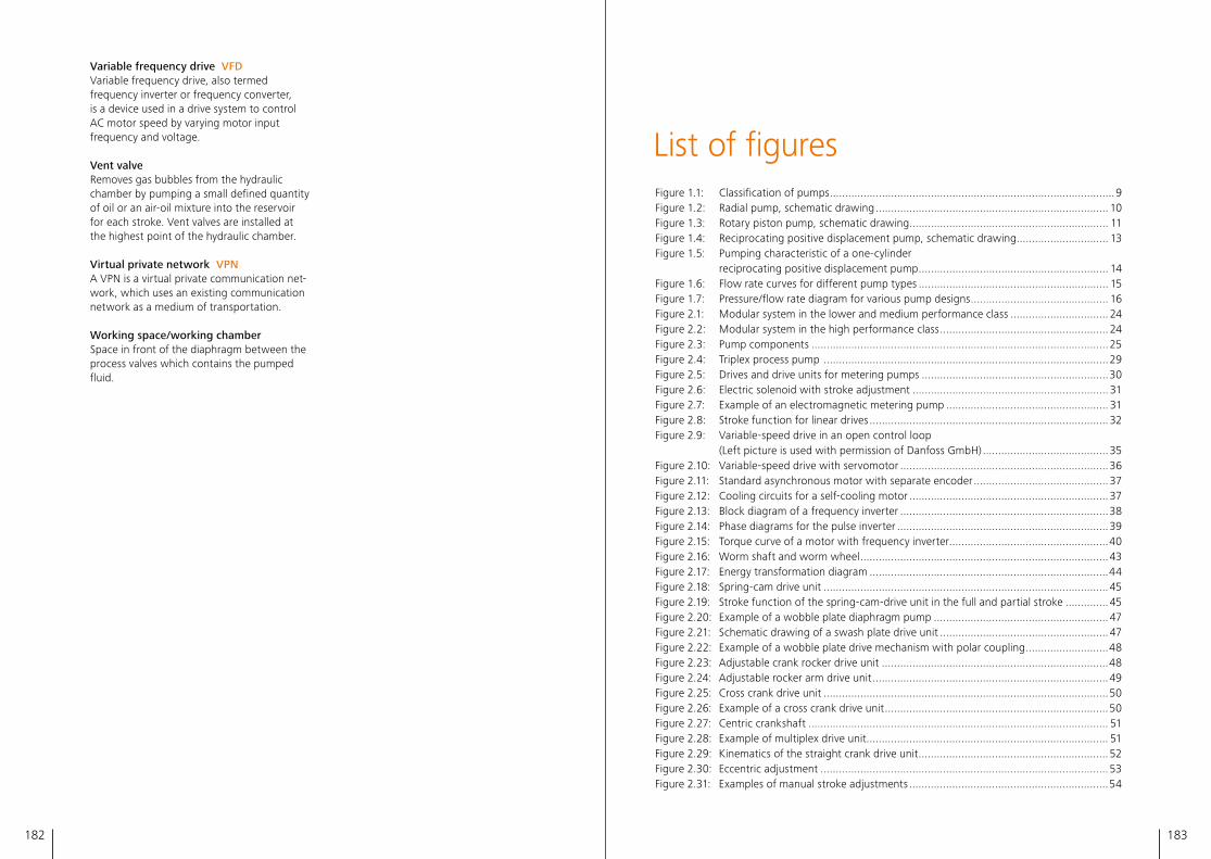
182 183
Variable frequency drive VFDVariable frequency drive, also termed frequency inverter or frequency converter, is a device used in a drive system to control AC motor speed by varying motor input frequency and voltage�
Vent valveRemoves gas bubbles from the hydraulic chamber by pumping a small defined quantity of oil or an air-oil mixture into the reservoir for each stroke� Vent valves are installed at the highest point of the hydraulic chamber�
Virtual private network VPNA VPN is a virtual private communication net-work, which uses an existing communication network as a medium of transportation�
Working space/working chamberSpace in front of the diaphragm between the process valves which contains the pumped fluid�
List of figuresFigure 1�1: Classification of pumps ���������������������������������������������������������������������������������������������9Figure 1�2: Radial pump, schematic drawing ���������������������������������������������������������������������������� 10Figure 1�3: Rotary piston pump, schematic drawing ����������������������������������������������������������������� 11Figure 1�4: Reciprocating positive displacement pump, schematic drawing ������������������������������ 13Figure 1�5: Pumping characteristic of a one-cylinder reciprocating positive displacement pump �������������������������������������������������������������� 14Figure 1�6: Flow rate curves for different pump types �������������������������������������������������������������� 15Figure 1�7: Pressure/flow rate diagram for various pump designs ��������������������������������������������� 16Figure 2�1: Modular system in the lower and medium performance class �������������������������������� 24Figure 2�2: Modular system in the high performance class ������������������������������������������������������� 24Figure 2�3: Pump components �������������������������������������������������������������������������������������������������25Figure 2�4: Triplex process pump ���������������������������������������������������������������������������������������������29Figure 2�5: Drives and drive units for metering pumps �������������������������������������������������������������30Figure 2�6: Electric solenoid with stroke adjustment ���������������������������������������������������������������� 31Figure 2�7: Example of an electromagnetic metering pump ����������������������������������������������������� 31Figure 2�8: Stroke function for linear drives ������������������������������������������������������������������������������ 32Figure 2�9: Variable-speed drive in an open control loop (Left picture is used with permission of Danfoss GmbH) ����������������������������������������� 35Figure 2�10: Variable-speed drive with servomotor ��������������������������������������������������������������������36Figure 2�11: Standard asynchronous motor with separate encoder �������������������������������������������� 37Figure 2�12: Cooling circuits for a self-cooling motor ����������������������������������������������������������������� 37Figure 2�13: Block diagram of a frequency inverter ��������������������������������������������������������������������38Figure 2�14: Phase diagrams for the pulse inverter ���������������������������������������������������������������������39Figure 2�15: Torque curve of a motor with frequency inverter ����������������������������������������������������40Figure 2�16: Worm shaft and worm wheel ���������������������������������������������������������������������������������43Figure 2�17: Energy transformation diagram ������������������������������������������������������������������������������44Figure 2�18: Spring-cam drive unit ���������������������������������������������������������������������������������������������45Figure 2�19: Stroke function of the spring-cam-drive unit in the full and partial stroke �������������� 45Figure 2�20: Example of a wobble plate diaphragm pump ��������������������������������������������������������� 47Figure 2�21: Schematic drawing of a swash plate drive unit ������������������������������������������������������� 47Figure 2�22: Example of a wobble plate drive mechanism with polar coupling ���������������������������48Figure 2�23: Adjustable crank rocker drive unit ��������������������������������������������������������������������������48Figure 2�24: Adjustable rocker arm drive unit �����������������������������������������������������������������������������49Figure 2�25: Cross crank drive unit ���������������������������������������������������������������������������������������������50Figure 2�26: Example of a cross crank drive unit �������������������������������������������������������������������������50Figure 2�27: Centric crankshaft �������������������������������������������������������������������������������������������������� 51Figure 2�28: Example of multiplex drive unit������������������������������������������������������������������������������� 51Figure 2�29: Kinematics of the straight crank drive unit �������������������������������������������������������������� 52Figure 2�30: Eccentric adjustment ���������������������������������������������������������������������������������������������� 53Figure 2�31: Examples of manual stroke adjustments �����������������������������������������������������������������54
184 185
Figure 2�32: Sectional view of an electric actuator (AUMA 2017) (Picture is used with permission of AUMA Riester GmbH & Co� KG) ����������������������� 55Figure 2�33: Example of an electric stroke adjustment ���������������������������������������������������������������56Figure 2�34: Examples of pneumatic stroke adjustments ������������������������������������������������������������57Figure 2�35: Plunger pump ���������������������������������������������������������������������������������������������������������58Figure 2�36: Work cycle/pressure course in the pump head ������������������������������������������������������� 59Figure 2�37: Plunger pump with installed diaphragm �����������������������������������������������������������������60Figure 2�38: Diaphragm pump with perforated disk and reservoir ���������������������������������������������� 61Figure 2�39: Diaphragm pump with perforated disks on both sides and PRV �����������������������������63Figure 2�40: Installing a control push rod in the diaphragm pump ���������������������������������������������65Figure 2�41: Control push rod in different work phases ��������������������������������������������������������������66Figure 2�42: Installation of a diaphragm spring in the diaphragm pump�������������������������������������67Figure 2�43: Different designs of pressure relief valves ���������������������������������������������������������������69Figure 2�44: Leak replenishing valves; adjustable, screw-in, flange-mounted ����������������������������� 70Figure 2�45: Vent valves; left: volumetric, right: continuous �������������������������������������������������������72Figure 2�46: Plunger pump head ������������������������������������������������������������������������������������������������73Figure 2�47: Functional diagram of an air-operated double-diaphragm pump ���������������������������� 75Figure 2�48: Mechanically-driven diaphragm ������������������������������������������������������������������������������ 75Figure 2�49: Plastic diaphragm between perforated disks ����������������������������������������������������������77Figure 2�50: Sandwich plastic diaphragm with control push rod ������������������������������������������������ 78Figure 2�51: Diaphragm with permanently attached control push rod ��������������������������������������� 78Figure 2�52: Sandwich plastic diaphragm with diaphragm spring ����������������������������������������������� 79Figure 2�53: Special diaphragm clamping and small working space for high pressures ���������������80Figure 2�54: Hydraulic metal diaphragm pump head with perforated disk ��������������������������������� 81Figure 2�55: Metal diaphragm pump head with snifting valve ����������������������������������������������������82Figure 2�56: Diaphragm pump head with heating jacket ������������������������������������������������������������83Figure 2�57: Remote heads with separated valve head with and without diaphragm �����������������84Figure 2�58: Fluid valves, basic designs ���������������������������������������������������������������������������������������86Figure 2�59: Example of a plate-shaped wing valve ��������������������������������������������������������������������88Figure 2�60: Example of an annular valve �����������������������������������������������������������������������������������89Figure 2�61: Suspension valves, designs �������������������������������������������������������������������������������������90Figure 2�62: Diaphragm pumps move a wide range of fluids ������������������������������������������������������ 91Figure 2�63: Various diaphragms laminated with elastomer and elastomer/PTFE composite material ����������������������������������������������������������������� 92Figure 2�64: PTFE/multi-layer diaphragm family �������������������������������������������������������������������������� 93Figure 2�65: Pump with diaphragm monitoring �������������������������������������������������������������������������� 93Figure 2�66: Sandwich diaphragm for diaphragm monitoring ����������������������������������������������������94Figure 2�67: Double-diaphragm with intermediate chamber ������������������������������������������������������95Figure 3�1: Efficiency diagram in accordance with EC Regulation 640/2009 ����������������������������98Figure 3�2: Schedule for introducing minimum efficiency levels �����������������������������������������������99Figure 3�3: API 674, Piston and plunger pumps ����������������������������������������������������������������������100Figure 3�4: API 675, Typical liquid end pumps ������������������������������������������������������������������������ 103Figure 3�5: API 675, Steady state flow accuracy ���������������������������������������������������������������������104Figure 3�6: API 675, Repeatability and linearity ����������������������������������������������������������������������104Figure 4�1: Process & instrumentation diagram ���������������������������������������������������������������������� 109Figure 4�2: Relative compressibility for various fluids ���������������������������������������������������������������111Figure 4�3: Starting up with closed circular piping �������������������������������������������������������������������112Figure 4�4: System for metering melt in a heating cabinet ������������������������������������������������������ 114
Figure 4�5: Metering slurries ��������������������������������������������������������������������������������������������������� 114Figure 4�6: Calculated suction-side pressure curve ����������������������������������������������������������������� 120Figure 4�7: Static pressure in the piping system ���������������������������������������������������������������������� 121Figure 4�8: Dynamic pressure in the piping system ����������������������������������������������������������������� 123Figure 4�9: Laminar flow �������������������������������������������������������������������������������������������������������� 125Figure 4�10: Pressure waves in the piping system ��������������������������������������������������������������������� 127Figure 4�11: Fluid forces acting on the inside of a pipe ������������������������������������������������������������� 128Figure 4�12: Damper types, schematic drawing ������������������������������������������������������������������������ 130Figure 4�13: Functionality of a diaphragm damper, schematic diagram ������������������������������������ 131Figure 4�14: Flow-through diaphragm damper, schematic drawing ������������������������������������������ 131Figure 4�15: Liquid dampers, schematic drawing ��������������������������������������������������������������������� 132Figure 4�16: Liquid damper, functional diagram ����������������������������������������������������������������������� 133Figure 4�17: Pulse developments for different damper types ���������������������������������������������������� 134Figure 4�18: Maximum permissible pressure amplitude for a 3" diameter as a function of excitation frequency, in accordance with API 674/675 ���������������� 135Figure 4�19: Exemplary overview of typical faults ��������������������������������������������������������������������� 143Figure 4�20: Measured values of a condition monitoring system ���������������������������������������������� 143Figure 4�21: State variables of a condition monitoring system ��������������������������������������������������144Figure 4�22: Recording of "good condition" ����������������������������������������������������������������������������� 145Figure 4�23: Hydraulic leakages ������������������������������������������������������������������������������������������������ 145Figure 4�24: Solid-borne sound diagrams for monitoring the fluid valves ��������������������������������� 146Figure 4�25: Pressure curve of a three-headed pump with a defective suction valve at head A ����������������������������������������������������������������������������������������������������� 146Figure 4�26: Theoretical volume flow pulsation of a three-headed pump ��������������������������������� 147Figure 4�27: Theoretical volume flow pulsation of two synchronized three-headed pumps ����� 148Figure 4�28: Protocol for plunger distance and plunger velocity at constant angular veloci ty of the motor shaft on the discharge side ������������������ 150Figure 4�29: Plunger distance and target plunger velocity on the discharge side ���������������������� 151Figure 4�30: Trapezoidal linearization and synchronization of two pumps �������������������������������� 152Figure 4�31: Trapezoidal linearization �������������������������������������������������������������������������������������� 153Figure 4�32: Residual ripple of an optimized flow rate curve with trapezoidal linearization ������ 153Figure 4�33: Plunger velocity and flow rate, double pump arrangement ���������������������������������� 154Figure 4�34: Plunger velocity and flow rate, triple pump arrangement ������������������������������������� 155Figure 5�1: Energy efficiencies of pumps �������������������������������������������������������������������������������� 158Figure 6�1: Methanol injection package with liquid-type dampers ����������������������������������������� 162Figure 6�2: Odorizing system with pumps, tank and measuring unit �������������������������������������� 163Figure 6�3: Remote head pump with separation of the remote valve head and pump drive unit ����������������������������������������������������������������������������164Figure 6�4: Metering system with diaphragm pump technology �������������������������������������������� 165Figure 6�5: Schematic of caustic production with and without inline caustic dilution system ������������������������������������������������������������������� 166Figure 6�6: LEWA ecofoam to meter different blowing agents ����������������������������������������������� 167Figure 6�7: Principle of a supercritical fluid extraction plant ��������������������������������������������������� 169Figure 6�8: Pump heads in sanitary/hygienic design ��������������������������������������������������������������� 170Figure 6�9: LEWA ecoflow in plunger design or diaphragm design ����������������������������������������� 171Figure 6�10: LEWA EcoPrime Chromatography System from a single source ���������������������������� 173Figure 6�11: Large Hadron Collider by CERN ���������������������������������������������������������������������������� 174Figure 6�12: Solutions for microflow metering applications ������������������������������������������������������ 175
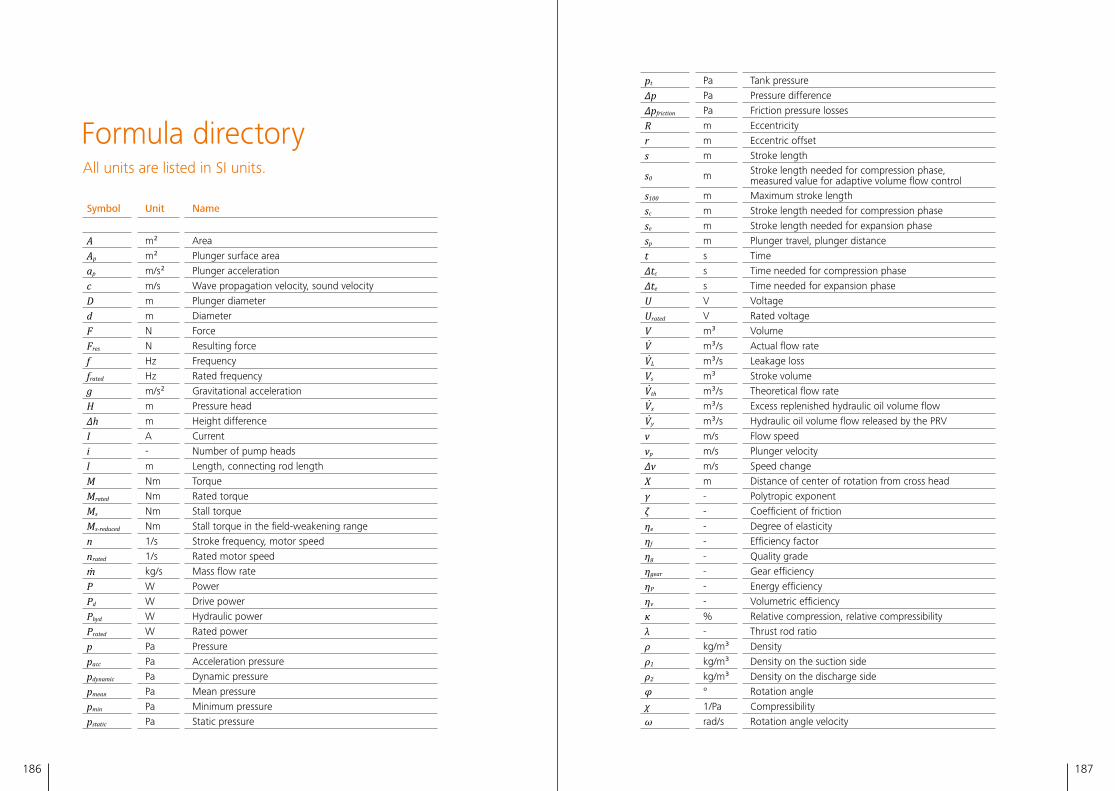
186 187
Symbol Unit Name
A m² Area
Ap m² Plunger surface area
ap m/s² Plunger acceleration
c m/s Wave propagation velocity, sound velocity
D m Plunger diameter
d m Diameter
F N Force
Fres N Resulting force
f Hz Frequency
frated Hz Rated frequency
g m/s² Gravitational acceleration
H m Pressure head
∆h m Height difference
I A Current
i - Number of pump heads
l m Length, connecting rod length
M Nm Torque
Mrated Nm Rated torque
Ms Nm Stall torque
Ms-reduced Nm Stall torque in the field-weakening range
n 1/s Stroke frequency, motor speed
nrated 1/s Rated motor speed
m ̇ kg/s Mass flow rate
P W Power
Pd W Drive power
Phyd W Hydraulic power
Prated W Rated power
p Pa Pressure
pacc Pa Acceleration pressure
pdynamic Pa Dynamic pressure
pmean Pa Mean pressure
pmin Pa Minimum pressure
pstatic Pa Static pressure
Formula directoryAll units are listed in SI units�
pt Pa Tank pressure
Δp Pa Pressure difference
Δpfriction Pa Friction pressure losses
R m Eccentricity
r m Eccentric offset
s m Stroke length
s0 m Stroke length needed for compression phase, measured value for adaptive volume flow control
s100 m Maximum stroke length
sc m Stroke length needed for compression phase
se m Stroke length needed for expansion phase
sp m Plunger travel, plunger distance
t s Time
∆tc s Time needed for compression phase
∆te s Time needed for expansion phase
U V Voltage
Urated V Rated voltage
V m³ Volume
V ̇ m³/s Actual flow rate
V ̇L m³/s Leakage loss
Vs m³ Stroke volume
V ̇th m³/s Theoretical flow rate
V ̇x m³/s Excess replenished hydraulic oil volume flow
V ̇y m³/s Hydraulic oil volume flow released by the PRV
v m/s Flow speed
vp m/s Plunger velocity
∆v m/s Speed change
X m Distance of center of rotation from cross head
γ - Polytropic exponent
ζ - Coefficient of friction
ηe - Degree of elasticity
ηf - Efficiency factor
ηg - Quality grade
ηgear - Gear efficiency
ηP - Energy efficiency
ηv - Volumetric efficiency
κ % Relative compression, relative compressibility
λ - Thrust rod ratio
ρ kg/m³ Density
ρ1 kg/m³ Density on the suction side
ρ2 kg/m³ Density on the discharge side
φ ° Rotation angle
χ 1/Pa Compressibility
ω rad/s Rotation angle velocity
188 189
Reference listANSI/API Standard 610, Centrifugal Pumps for Petroleum, Petrochemical and Natural Gas In-dustries, 11th Edition, September 2010, Errata, July 2011�
ANSI/HI 6�6, Reciprocating Pump Tests, Hy-draulic Institute, Parsippany, New Jersey, 2015�
ANSI/NACE MR0103/ISO 17495-1:2016, Petro-leum, petrochemical and natural gas indus-tries – Metallic materials resistant to sulfide stress cracking in corrosive petroleum refining environments, Approved November 23, 2015�
API 674, Positive Displacement Pumps – Recip-rocating, Edition December 2010, Errata May 2014, Errata 2, April 2015, Reaffirmed, Novem-ber 2016�
API 675, Positive Displacement Pumps – Con-trolled Volume for Petroleum, Chemical, and Gas Industry Services, API Standard 675, 4th Edition, November 2012, Errata, June 2014, Er-rata 2, April 2015�
AUMA, AUMA Explosionsgeschütze AntriebeSAEx und SAREx, 2017, https://www�auma�com/index�php?eID=ix_product_ajax&action=download&fileUID=1850 (accessed 07-13-2017)�
AUMA, Homepage Documents, 2017, https://www�auma�com/de/dokumente (accessed 07-13-2017)�
Böswirth, Leopold, Technische Strömungsleh-re, Lehr- und Übungsbuch, 8th Edition, Wies-baden: Viweg & Teubner, 2010�
Canadian Standards Association, Canadian Electrical Code, 24th edition, 2018�
Commission regulation (EC) No 640/2009, Implementing Directive 2005/32/EC of the
European Parliament and of the Council with regard to ecodesign requirements for electric motors, 07-22-2009�
Demtröder, Wolfgang, Experimentalphysik 1, Mechanik und Wärme, 4th Edition� Berlin, Hei-delberg, New York: Springer, 2006�
Die Sterling Fluid Systems-Gruppe, Grundla-gen für die Planung von Kreiselpumpenanla-gen, 7th revised and extended edition, Itze-hoe: Sterling SIHI GmbH, 2000�
DIN EN ISO 3744, Acoustics – Determination of sound power levels and sound energy levels of noise sources using sound pressure – Engi-neering methods for an essentially free field over a reflecting plane, February 2011�
DIN EN ISO 12100, Safety of machinery – Gen-eral principles for design – Risk assessment and risk reduction, 2010�
DIN EN 809, Pumps and pump units for liquids – Common safety requirements, 2012�
DIN EN 60034-30-1:2014-12, Rotating electri-cal machines – Part 30-1: Efficiency classes of line operated AC motors, December, 2014�
Directive 1999/92/EC of the European Parlia-ment and of the Council on minimum require-ments for improving the safety and health protection of workers potentially at risk from explosive atmospheres (15th individual Direc-tive within the meaning of Article 16 (1) of Di-rective 89/391/EEC), 12-16-1999�
Directive 2006/42/EC of the European Parlia-ment and of the Council on machinery, and amending Directive 95/16/EC, 05-17-2006�
Directive 2009/125/EC of the European Parlia-ment and of the Council establishing a frame-
work for the setting of ecodesign requirements for energy-related products, 10-21-2009�
Directive 2014/34/EU of the European Parlia-ment and of the Council on the harmonisation of the laws of the Member States relating to equipment and protective systems intended for use in potentially explosive atmospheres Text with EEA relevance, 02-26-2014�
IEC 60079-0:2017, Explosive atmospheres –Part 0, Equipment General requirements, 2017�
International Electrotechnical Commission Sys-tem for Certification to Standards Relating to Equipment for Use in Explosive Atmospheres, IECEx COC, 2008�
ISO/IEC 80079-34:2011, Explosive atmospheres – Part 34: Application of quality systems for equipment manufacture, 2011�
Eichhammer, Fleiter, Schlomann, Strigel, Ener-gieeffizienzdaten für den Kimaschutz, Klima-bericht, Dessau-Roßgau, Umweltbundesamt, 2012�
Eifler, Schlücker, Will-Küttner, Spicher, Kol-benmaschinen, 7th Edition, Wiesbaden: Vieweg & Teubner, 2009�
Energy institute, Guidelines for the Avoidance of Vibration Induced Fatigue Failure in Process Pipework, 2nd Edition, London: Energy institute, January 2008�
Engineering Dynamics, Vibrations in Recip-rocating Machinery and Piping Systems, EDI Report 41450, Texas, Engineering Dynamics, May 1995�
Fritsch, Horst, Dosierpumpen: Grundlagen, Konstruktionen, Anwendung, Landsberg, Ver-lag moderne Industrie, 1989�
Hydraulic Institute, Hydraulic Institute Pump Systems Assessment (PSA) Certificate Program Focuses on Methods to Identify Pump Efficien-cy Improvement Opportunities, http://empoweringpumps�com/hydraulic-in-stitute-pump-systems-assessment-certificate-program-focuses-on-methods-to-identify-pump-efficiency-improvement-opportunities (accessed 08-10-2017)�
ISO 13710, Petroleum, petrochemical and natural gas industries – Reciprocating positive displacement pumps, 1st Edition, 07-01-2004�
Wachel, Tison, Price, The Effect of Pulsation on Cavitation in Reciprocating Pump Systems, Presented at the Energy-Sources Technology Conference and Exhibition, Houston, January 22-25, 1989�
Kiefer, Susan Werner, Sound Speed in Liquid-Gas Mixtures: Water-Air and Water-Steam. Journal of geophysical research (University of California), no� Vol� 82, No� 20, July 1977: 2895-2904�
NACE MR 0175/ISO 15156:2015, Petroleum and natural gas industries – Materials for use in H₂S-containing environments in oil and gas production, 2015�
NFPA National Fire Protection Association, Na-tional Electrical Code (NEC), 2017�
NORSOK Standard M-501, Surface preparation and protective coating, 6th Edition, February 2012�
NORSOK Standard M-630, Material data sheets for piping, Rev� 4� January 2004�
NORSOK Standard M-650, Qualification of manufacturers of special materials, 4th Edition, September 2011�
NORSOK, Standard Norge, www�standard�no, (accessed 09-04-2017)�
Piesche, Prof� Dr�-Ing�, Mehrphasenströmun-gen, Kap. 6, Vorlesungsskript, Institut für Me-chanische Verfahrenstechnik, Universität Stutt-gart, WS 2002/2003�
Seehofer, Uwe, Untersuchungen am Memb-ranpumpen im Teilkavitationsbereich, Diplom-arbeit, Leonberg, 1996�
VDMA, NPSH bei oszillierenden Verdränger-pumpen, 1st Edition, Frankfurt a� M�, Maschi-nenbau-Verlag GmbH, 1989�
190 191
Index
AAcceleration head�������������������������������������� 124Acceleration pressure ������������������119, 123, 124Acceleration pressure fluctuation �������124, 119Acoustic resonances ���������������������������������� 127Actuator ������������������������������������31, 54-57, 139 Electric ������������������������������������������������ 54-56 Explosion-proof ����������������������������������������55 Pneumatic �������������������������������������������������56 Positioning accuracy ���������������������������������56 Rotary �������������������������������������������������������55 Solenoid ���������������������������������������������������31Air motor �����������������������������������������26, 42, 56Air vessel ��������������������������������������������129, 130Air-operated diaphragm pump ��������������������74Annular valve�����������������������������������������88, 89ANSI/HI 6�6-2015 ��������������������������������������101 Performance test �����������������������������101, 105API 618 ������������������������������������������������������136API 674 ��������������99-102, 105, 117, 119, 134-136 Acceleration pressure fluctuation ������������ 119 Acceptance tests �������������������������������������101 Cavitation ����������������������������������������������� 117 Material specification������������������������������101 Maximum permissible pressure pulsation �135 Mechanical analysis ��������������������������������136 NPIPR test �����������������������������������������������102 NPSHR test ���������������������������������������������102 Pulsation analysis ����������������������������� 134-137 Pulsation and vibration control techniques ����������������������������������������������105 Required nozzle forces ����������������������������101 Service life ����������������������������������������������101API 675 �����������������������������������������99, 102-105 Acceleration pressure fluctuation ������������ 119 Cavitation ����������������������������������������������� 117 Linearity ��������������������������������������������������104 NPIPR test �����������������������������������������������105 Performance test �����������������������������101, 105
Permitted designs ���������������������������� 102-103 Pulsation analysis ����������������������������� 134-137 Pulsation and vibration control techniques ����������������������������������������������105 Rated capacity ���������������������������������101, 104 Repeatability �������������������������������������������104 Steady state flow accuracy����������������������104API 688 ����������������������������������������������136, 137Asynchronous motor ����������������������������� 34-40ATEX directive ���������������������������������������������97Autosampler ���������������������������������������������� 171
BBaffle plate ����������������������������������������� 131, 132Ball valve ����������������������������������������������87, 180Barrier fluid ����������������������������������������� 73, 160Batch control ��������������������������������������������� 141Batch process �������������������������������������������� 171Bernoulli's principle �����������������������������������122Bingham fluid �������������������������������������������� 113Biomass to liquid ��������������������������������163, 176Bladder type damper �������������������������� 129-132Bleach ������������������������������������������������������� 116Boxer drive unit �������������������������������������28, 51
CCanadian Electrical Code ����������������������97, 176Canned motor ���������������������������������������������16Capacitance ������������������������������������������������41Caustic solution �����������������������������������������166Cavitation �� 14, 113, 116-119, 124, 134, 139, 159 CEC ������������������������������������������������������97, 176Centrifugal pump �������������������������������������9-10 Advantages & disadvantages ��������������������10 High-speed ����������������������������������������10, 158 Multi-stage ����������������������������������������10, 159 Performance spectrum �����������������������������10CERN �������������������������������������������������� 173-174Characteristic curve control ����������������138, 139
Chemical reaction behavior ���������������� 110, 115Chlorides ��������������������������������������������������� 116Closed control loop �������������������������36, 28, 55Closing body ����������������������������������������� 85-89Closing delay ����������������������������20, 86, 87, 176Closing energy��������������������������������������� 86-88CMS �������������������������������������141, 173, 174, 177 Measured values ������������������������������143, 179 State variables �����������������������������������������144 System approach ������������������������������������144Coefficient of friction �������������������������125, 126Combustion engine ���������������� 26, 42, 100, 174Commission Regulation (EC) 640/2009 �������98Compressibility ������������������������� 58, 71, 74, 87, ������������������ 110-111, 113, 116-117, 119, 126, 132Condition monitoring system �������������������108, ����������������������������������������������������141-144, 177Cone valve ������������������������������������� 86, 88, 180Constant flux range �������������������������������39, 40Constant speed drive �����������������������������34, 35Construction kit �������������������������������23, 25, 26Control push rod ������������ 65-66, 68, 77-79, 82Controlled Volume Positive Displacement Pumps ���������������������������������102Cooling jacket �������������������������������� 20, 21, 174Corrosion ������������ 19, 22, 85, 92, 101, 106, 116 Pitting ����������������������������������������������������� 116 Protection ����������������������������������������� 22, 106 Rates������������������������������������������������������� 116 Surface ����������������������������������������������22, 116 Corrosion fatigue �������������������������������������� 116Corrosion protection class ���������������������������22Costs Acquisition ���������������������������������������139, 181 Energy ����������������������������������������������������160 Life cycle ������������������������������ 19, 73, 156, 160 Maintenance ������������������������19, 60, 106, 160 Manufacturing ����������������������������������� 64, 66Crank drive ��������������������25-26, 43, 48-53, 100Crank-rocker drive unit ��������������������������������48Creep strength ��������������������������������������������92Cross crank drive unit ����������������������������������50Dampers gas-filled ���������������������������120, 130, 134, 180 liquid �����������������������������������������������120, 132
DDamping devices ������������������������ 120, 128, 129
Damping installations Flow rate smoothing �������������������������������129Damping properties ����������������������������������130DC link voltage ��������������������������������������39, 41Degassing valve ������������������������������������71, 177Degree of elasticity ������������������������������������157Density ���������������������������������18-21, 77, 81, 85, ��������������������������������������110, 113, 121, 137, 168 Deviation list������������������������������������������������99Diaphragm ��� 12, 14, 17, 27, 60-68, 90-95, 170 Damage ������������������������������ 93, 140-141, 143 Directly driven ������������������������������74, 76, 79 Holder ������������������������������������������������������75 Hydraulically driven ��������� 14, 76-84, 102, 118 Materials ������������������������ 20, 77, 92, 130, 169 Mechanically driven ���� 14, 27, 75-76, 91, 102 Metal ��������������������17, 64, 77, 80-82, 92, 175 Monitoring ���� 28, 68, 76, 84, 91, 93-95, 172 Overstretching ���������������������������� 61-64, 177 Polymer ��������������������������� 77-80, 81, 92, 160 Positioning �������������������������������������66-67, 78 Sandwich �� 28, 76, 78, 79, 91-94, 116, 143-144 Spring ������������������������������������� 67-68, 79, 93 Diaphragm damper ���������������������������� 129-132Diaphragm positioning system �������66, 67, 177Diaphragm pump Advantages and disadvantages�����������������14 Areas of application ����������������������������33, 72 Multiplex ������� 13, 17, 28, 51, 57, 67, 134, 170 Performance spectrum �����������������������������15Diaphragm pump head Air-operated ����������������������������������������74-75 Directly driven ������������������������������������� 74-76 Hydraulically actuated �������������14, 27, 76-84, ��������������������������������������������������������102, 118 Mechanically actuated ��14, 27, 75-76, 91, 102Diaphragm rupture monitoring����������� 140-141Dilatant ����������������������������������������������������� 113DIN EN 60079 ���������������������������������������������97DIN EN 80079 ���������������������������������������������97DIN EN ISO 12944 ���������������������������������������22DIN EN ISO 8044 ��������������������������������������� 116Directive 1999/92/EC ����������������������������������97Discharge valve ������������������������ 13, 27, 85, 115Displacement pump Reciprocating ��������� 8-9, 12-16, 18-21, 23, 25, ����������������������������52, 100-105, 109, 118, 124, ��������������������������� 126-128, 134, 136, 156-159
192 193
Rotary ��������������������������������� 8-9, 10-12, 15-16Displacer ������������������������������������ 10-13, 27, 58 Position �������������������������������������� 37, 143, 149 Velocity���������������������������������������������������149Drive unit�����������������������17, 21, 25, 26, 28, 29, ���������������������������� 43-57, 69, 105, 137, 164, 174 Boxer ��������������������������������������������������28, 51 Cooling �����������������������������������������������������20 Crank drive ����������������������������������������� 50-53 Crank-rocker ���������������������������������������������48 Cross crank �����������������������������������������������50 Eccentric adjustment ���������������������������������53 Rocker arm ��������������������������������������� 49, 105 Spring cam ����������������������������������������� 44-46 Straight crank �����������������������50-53, 150, 151 Swash plate ���������������������������������������� 46-48 Wobble plate �������������������������� 26, 43, 46-48Drive ������������������ 25, 28, 29-38, 41-42, 63, 70, �������������������� 74, 75, 89, 100, 107, 149, 174-175Drive power ������������������������������������18, 41, 156Dynamic pressure ������������������������119, 122, 123
EEccentric adjustment �����������������������������������53Eccentric offset ������������������������������������������ 151Ecodesign Directive ����������������������������� 98, 156Eco-friendly design ��������������������������������������98Efficiency Energy ������������������������������������������9, 156-157 Losses �������������������������������������������� 9, 10, 157 Volumetric ��������������18, 111, 113, 116-117, 157Electric actuator ������������������������������ 22, 54-56Electric motor ����������� 12, 25, 31, 33-38, 55, 98 Efficiency rating ����������������������������������������98EN 809 ��������������������������������������������������������96EN ISO 12100 ����������������������������������������������96Encoder �������������������������������������������������36, 37Energy costs ����������������������������������������������160Energy efficiency ���������������������������� 9, 156, 157Energy productivity ����������������������������156, 178EU Declaration of Conformity ����������������������96EU directive 2014/34/EU �����������������������������97Excitation frequency �������������128, 129, 135-136Explosion Protection ������������ 32, 55, 56, 96-97Explosion Protection Directive ���������������������96Explosion zone ��������������������������������������������22Explosion-proof actuator �����������������������������55Extruder ���������������������������������������������165, 167
FFatigue strength ������������������������������������������92Field-weakening range ��������������������������������40Field-weakening range ��������������������������������40Flow profile �����������������������������������������������125Flow rate �������������������������15-16, 18, 20-21, 59, �������������������������� 62, 70, 72, 101, 102, 104, 111, ������������������������129, 137, 139, 147, 158, 174-175 Accuracy ���������������������������������������������������34 Actual �������������������������������������������������������18 Adjustment �������������� 25, 26, 35, 57, 105, 149 Centrifugal pump ������������������������ 9, 10, 15-16 Control ������������������������35, 138, 148, 149-155 Diaphragm pump ��������������������������������������13 Directly driven diaphragm pump ���������74, 67 Hydraulicly driven metal diaphragm diaphragm pump ��������������������������������������82 Hydraulicly driven polymer diaphragm pump ��������������������������������������79 Losses ����������������������������������������� 86, 117, 119 Mechanically driven diaphragm pump ������76 Pulsating ����������������������������118, 129-131, 149 Reciprocating positive displacement pump ����������������������� 13-16, 23 Rotary positive displacement pump 12, 15-16 Theoretical ������������������������������������������������18Flow rate curve ������������������������������37, 149-153Flow speed ������������������� 115, 122, 123, 125, 137Flow-through diaphragm damper �������������� 131Flue gas cleaning ��������������������������������170, 171Fluid Bingham fluid ����������������������������������������� 113 Chemical reaction behavior ������������� 110, 115 Composition ������������������������� 21, 71, 116, 161 Compressibility ����������������� 18, 20-21, 58, 87, ����������������������110-111, 113, 117, 119, 126, 132 Density �������18-21, 85, 110, 113, 121, 137, 168 Dilatant ��������������������������������������������������� 113 Flow speed ���������������� 115, 122, 123, 125, 137 Kinematics ��������������������������������������� 149-155 Melt ����������������� 21, 83, 113-114, 165, 167, 170 Newtonian ������������������������ 112, 125, 126, 180 Non-Newtonian ��������������������������������112-113 Outgassing upon starting up ������������������ 116 Pseudoplastic ������������������������������������������ 113 Radioactive �����������������������������������������20, 84 Rheopectic ��������������������������������������������� 112 Shear-thickening ������������������������������������� 113
Shear-thinning ���������������������������������������� 113 Slurry ��������������������������������������������79, 82, 89 Solid content �������������������������������������21, 101 Sound velocity ������������������� 115, 123-124, 127 Split off of gases ������������������������������������� 116 Suspension �����������������������������������������21, 90 Temperature and pressure dependency �� 113 Thixotropic ��������������������������������������������� 112 Types ��������������������������������������������������������91 Vapor pressure ���������20, 85, 91, 102, 111-112, ���������������������113, 117, 118-120, 126, 136, 168 Viscosity ���������������� 11, 12, 17, 20, 85, 86, 87, ���������������������������� 112-113, 114, 125, 137, 154Fluid mechanics ���������������������������������� 121-129Fluid temperatures���������������������������20, 81, 82Fluid valve �������������� 25, 27, 28, 84, 85-90, 144Flushing liquid ���������������������������������������������73Fraction collector �������������������������������������� 171Frequency inverter �������������� 20, 25, 30, 34-36, ������������������������������38-41, 57, 98, 138-139, 141Friction pressure losses �������� 113, 119-120, 122, ���������������������������������������������125-126, 131, 132
GGas removal valve ���������������������69, 71, 72, 178Gas-filled damper ����������������������� 120, 130, 134Gear pump �����������������������������������������9, 12, 25Gear unit ������������������������������������������������42-43 External �������������������������������������� 30, 42, 100 Integrated �������������������������������������������������42German Technical Instructions on Air Quality Control (TA Luft) �����������������160
HHART Protocol ���������������������������������������������56Head ����������������������������������������������������19, 118Heat of compression ���������������������������� 21, 111High-stroke characteristic ���������������������70, 178Hydraulic chamber ������������� 60-68, 69, 70, 71, �����������������������������������������������90, 93, 143, 144Hydraulic motor �������������������������������������������42Hydraulic power ������������������������ 15, 18, 26, 58Hydraulic valves ���������������������������� 68, 69 , 157Hydraulically driven polymer diaphragm pump Advantages & disadvantages ��������������������79Hydrogen peroxide ������������������������������������ 116Hydrostatic paradox ����������������������������������122Hygienic design ������������������������������������ 17, 170
IIEC 60034-30 ����������������������������������������������98IEC 60079 ���������������������������������������������������97IEC 61508 �������������������������������������������138, 181IEC 80079 ���������������������������������������������������97IECEx �����������������������������������������������������������97Initial pressure peak �����������������������������������125Inlet pressure loss ������������� 20, 21, 85, 102, 179Instrumentation��������������������108-109, 137-138Instrumentation and control engineering �������� ����������������������������������������������������137, 179, 180Intermediate fluid �������������������������������������� 116International Efficiency Classes ��������������������98Investment costs ���� 10, 12, 14, 19, 20, 159, 160ISO 13710 ��������������������������������������������������101ISO 3744 ���������������������������������������������������102
KKinematics ������������������������ 45, 46, 52, 117, 119, �������������������������������������������� 123, 124, 149, 155
LLaminar flow ���������������������������������������������125LDHI ���������������������������������������������������161, 179Leak replenishing valve ����������61-62, 65, 68-71Leakage loss ������������������������������� 11, 15, 61, 62Leaked fluid �������������������������������������������������73Life cycle costs ����������������������� 19, 73, 156, 160Linear drive �������������������������������������������� 30-33 Advantages & disadvantages ��������������32, 33Linearity ���������������������������������������������� 46, 104Liquid damper ����������������������������� 120, 132-134Low-pulsation metering ����������������������������149
MMachinery directive �������������������������������������96Maintenance costs �����������������19, 60, 106, 160Manufacturing costs ���������������������������� 64, 66Mass flow �������������������������������� 18, 21, 110, 113Mechanically driven diaphragm pump ���������75 Advantages & disadvantages ��������������������76Melt �������������������21, 83, 113-114, 165, 167, 170Metering pump ���������������15-16, 18-22, 23, 25, ����������������������������������29, 31, 58, 108, 150, 156 Definition��������������������������������������������������15 Design �������������������������������������������������18-22Minimum efficiency levels ���������������������98, 99Minimum required suction pressure ���������� 119
194 195
Modular system �������������������������������23, 24, 85Monitoring systems �� 93, 95, 139, 140, 141-146Motion profile ������������������������������������������� 151Motion-controlled drive ������������������������������37Motor Thermal stress �������������������������������������������40 Voltage stress �������������������������������������������41MRSP ��������������������������������������������������������� 119Multi-layer diaphragms ��������������������������92, 94
NNACE ��������������������������������������������������� 99, 106NACE MR0103 �������������������������������������������106NACE MR0175/ISO 15156 ��������������������������106National Electrical Code �����������������������97, 179Natural frequency ��������������������������������������136NEC �������������������������������������������������������������97Newtonian fluid ������������������ 112, 125, 126, 180 Non-Newtonian fluid ��������������������������112-113NORSOK ����������������������������������������69, 105-107NPIP ����������������������� 101, 102, 105, 117, 118-120NPIPA �����������������������������������118-120, 105, 179NPIPR ���������������������������� 102, 105, 117, 118-120 NPSH ���������������������� 101, 102, 105, 117, 118-119NPSHA������������������������������������������������118, 179NPSHR ���������������������������������������� 102, 118, 179
OOdorant����������������������������������������������162, 181Odorizing system ���������������������������17, 162, 163Oil reservoir �������������������������������������������������20Open control loop ���������������������������������������35Operating costs �����������������������������������������159Operating criteria �����������������111, 116, 126, 136Operating data ��������������������������������������������19Orifices �������������������������������� 126, 128, 131, 134Outgassing �������������������������������������62, 68, 116Overall efficiency ���������������������������������������157Overdelivery ��������������������������������������� 116, 117Overload ����31-32, 37, 55, 56, 69, 116-117, 159
PP&ID ����������������������������������������������������������108Particle density ��������������������������������������������21Particle size ��������������������������������������������������21Perforated disk ��������61-66, 68, 77, 81, 82, 132Performance test ��������������������������������101, 105Peristaltic pump �������������������������������������������12
Permeation ���������������������������������79, 81-82, 95Phase shift ������������������������������������������147, 148PID controller ������������������������������������ 138, 180Pipe supports ��������������������������������������������136Piping design ��������������������������������������������� 116Piping system Mechanical analysis ��������������������������������136 Theoretical design ���������������������������������� 126Piping vibrations ���������������������������������124, 128Piston pump �������������������������������� 9, 11, 12, 100Plate valve ��������������������������������������������87, 180PLC ����������������������������������������������138-140, 180Plunger acceleration ��������������������� 52, 152, 154Plunger distance �������������������� 52, 150, 151, 153Plunger position control ������������������������������38Plunger pump ����������������������������������������58, 59 Advantages and disadvantages�����������������60Plunger pump head �������������������26, 58, 73, 90Plunger Acceleration ������������������������������� 52, 152, 154 Distance/travel ���������������52, 59, 150-151, 153 Velocity������������������������� 52, 59, 123, 150-155Pneumatic actuator �������������������������������������56Polymer diaphragm �������������������������� 77,81, 92Polytropic equation �����������������������������������130Polytropic exponent ����������������������������������130Positioning accuracy ������������������������������������56Positive displacement pump Reciprocating ��������� 8-9, 12-16, 18-21, 23, 25, ����������������������������52, 100-105, 109, 118, 124, ��������������������������� 126-128, 134, 136, 156-159 Rotary ��������������������������������� 8-9, 10-12, 15-16Power consumption ����������������������������������156Power pump ��������������������������������� 71, 100, 101Pressure Dynamic �����������������������������������119, 122, 123 Static ���������������������������������118, 119, 121, 122Pressure head ���������������������������������������19, 118Pressure pulsation ���������������������������������������������������������������������52, 115, 117, 120, 121, 126-136 Damping ��������������������������� 120, 128, 129-134Pressure relief valve ������������������� 63-64, 69-70, �����������������������������������71, 74, 76, 127, 136, 139Pressure resonance phenomena ���������������� 127Pressure waves ���������������������115, 127, 132, 133 Superposition ���������������������������������� 127, 133Process & instrumentation diagram �����������109Process control ����������������������38, 108, 138, 141
Process parameters ��������������������������18-22, 85Process pump �������������������������������������������������� ��������������������17, 29, 137, 147, 157-159, 163, 168 Definition��������������������������������������������������15Production Biofuels �����������������������������������������������17,163 Cable insulation ��������������������������������������164 Caustic soda ������������������������������������166, 181 Spreadable butter �����������������������������������169Production data acquisition �����������������������139Progressive cavity pump ���������������������������9, 12Pseudoplastic �������������������������������������������� 113Pulsation analysis ���������������������������������������108 Criteria ����������������������������������������������������135 Design approaches ���������������������������������135 Frequency spectrum ���������������� 132, 134, 135 Mechanical analysis ��������������������������������136 Shaking forces ���������������������������������135, 136Pulsation damping device ��������������������������120Pulsation study ��������������������������� 134, 135, 159Pulse frequency �������������������������������������������41Pump Classification �����������������������������������������������9 Selection ��������������������������������������������19, 109 Starting up ����������������������������������������� 112, 11 System ����������������������������������� 9, 29, 109, 159 Working principle ���������������������������������������8Pump construction kit ����������������������������23-28Pump head Heated ��������������������������� 21, 83, 111, 113, 171 Remote head design �������������������17, 163, 174Pumping chamber ������������������������������� 60, 180Pumping characteristics ����������������������������� 155Pyrolysis ����������������������������������������������������163
QQuality grade���������������������������������������������157
RRated capacity ������������������������������������101, 104Rated torque �����������������������������������������������40Reactive power ��������������������������������������������39Recipe metering �����������������������������17, 28, 181Reciprocating movement ����������� 12, 27, 49, 54Reciprocating positive displacement pump �������������������8-9, 12-16, 18-21, 23, 25, 52, 100-105,���������109, 118, 124, 126-128, 134, 136, 156-159Remote head design ����������������������17, 163, 174
Remote maintenance router ����������������������140Repeatability ���������������������������������������������104Reservoir ������������� 20, 61-63, 67, 69, 70-71, 77Resonance phenomena ����������������������������� 127Reversing valve ��������������������������������������������74Rheopectic ������������������������������������������������ 112Rocker arm drive unit �������������������������� 49, 105Rotary actuator �������������������������������������������55Rotary piston pump �����������������������������9, 11, 12Rotary positive displacement pumps Advantages & disadvantages ��������������������12 Performance spectrum �����������������������������12
SSCADA �����������������������������������������������172, 181Screw spindle pump ���������������������������������9, 12Sealing gap ����������������������������������������������11,15Secondary seal ��������������������������������������������73Self-monitoring of the measuring instrument �������������������������������������������������138Service life ���������������������������������19-22, 28, 73, �������������������������������� 85, 101, 137, 141, 160, 172Servomotor ����������������������������� 28, 36, 38, 149Settling rate ����������������������������������������������� 121Shear stress ������������������������������������������12, 180Shear-thickening ���������������������������������������� 113Shear-thinning ������������������������������������������� 113Shear velocity ��������������������������������������112-113Slurry �����������������������������������������������79, 82, 89Slurry valve ��������������������������������������������������89Snifting range ��������������������������������������������145Snifting valve �������������������� 69, 70, 82, 179, 181Sodium hypochlorite ��������������������������������� 116Solenoid actuator ����������������������������������������31Solidification point ��������������������������������������21Solids concentration ������������������������������������21Sonic emissions �����������������������������������������102Sound velocity ����������������������115, 123, 124, 127Span length calculation �����������������������������136Spring-cam drive unit ���������������������������� 44-46Spring-loaded valve ����������������������������� 86, 177Spur gear �����������������������������������������������42, 43Stall torque ��������������������������������������������39, 40Standardized chemical pump �����������������������10Standpipe �������������������������������������������129, 130Star drive �����������������������������������������������������51Starting up ����������������������������������������� 112, 116Startup procedure ���������������������������������66, 67

196 197
Static pressure ������������������������������������ 118-122Steady state flow accuracy ������������������������104Straight crank drive unit��������������������������51-53Straight crankshaft relation ����������������������� 151Stroke adjustment ���������20, 26, 28-32, 34, 45, ���������49, 50, 53, 54-56, 105, 138-139, 141, 170 Electrial ����������������������������������������������� 54-56 Manual �����������������������������������������������������54 Pneumatic ������������������������������������������� 56-57Stroke cylinder ���������������������������������������26, 30Stroke function ��������������������������������������32, 45Stroke limit ��������������������������������������45, 46, 89Suction valve ��������13, 20, 27, 71, 120, 146, 179Supercritical fluid ����������������� 110, 168, 169, 181Suspension �������������������������������������� 21, 90, 91Suspension valve �����������������������������������21, 90Swash plate drive unit ��������������������������� 46-48Synchronization ������������������� 147, 148, 152, 155Synchronous motor ������������������������34-40, 149Synchronous servomotors ���������������������������38
TTemperature range ��������������������������20, 28, 83Thixotropic ������������������������������������������������ 112Thrust rod ratio ������������������������������������52, 151Torque �������������������������������������� 25, 26, 34, 37, ���������������������������39-40, 42-44, 53, 54, 56, 63Trapezoidal linearization ���������������������152, 153Triethylaluminium �������������������������������������� 116Triple pump arrangement �������������������154, 155Turbulent flow �������������������������������������������125
VValve bodies ������������������������������������������������28Vane pump �����������������������������������������������9, 12Vapor pressure �����������20, 85, 91, 102, 111-112, ������������������������113, 117, 118-120, 126, 136, 168Variable eccentric �������������������� 28, 30, 53, 105Variable speed drive �������������������������������35-39V-drive ���������������������������������������������������������51Velocity ramp ��������������������������������������������152Vent valve ����������������������������������������� 69, 71-72Ventilation power ����������������������������������������36Vibration induced fatigue failure ���������������136Vibrations �������� 85, 105, 121, 124, 128, 136, 159Viscosity �������������������������11, 12, 17, 20, 85, 86, �������������������������� 87, 112-113, 114, 125, 137, 154Volume flow control ������������������������������������38
adaptive ������������������������������������������� 174-175Volumetric efficiency ���18, 111, 113, 116-117, 157Vortex structures ��������������������������������125, 133
WWave propagation velocity ������������������������ 127Wear parts ���������������������� 20, 32, 101, 159, 160 Wing valve ��������������������������������������������������88Wobble plate drive mechanism ������������ 46, 48Work cycle ��������������������������������������58, 59, 70Working space ����������������� 9, 12-13, 60, 62-64, ��������������������������������� 66-68, 73-77, 80, 90, 93Worm gear ��������������������������������������42, 44, 55Worm shaft �������������������������������������������������43
Many thanks to all the colleagues who participated in creating this book�
Authors:
Rüdiger BullertNina DietzMatthias Dörling Martin Dreher
Felix Theodor FarackFabian GeigerMarco KlinkigtMartin Schmid
Michael WimmerAnke-Dorothee Wöhr
Additional colleagues who helped in creating this book:
Dieter BareißHenk BeetsThomas Bökenbrink Joachim BundLea FreyRoman Gobitz-Pfeiffer
Albrecht HildHans-Joachim JohlKazim KonusMathias Möller Ronja PecherAntonio Polo
Roland SchwabJörg Sommer Kevin StreckerKarl-Heinz VoglerMaurice WirknerHeinz Woldering

LEWA GmbHUlmer Str� 1071229 LeonbergGermany