Embed Size (px)
Citation preview
Recent Trends in Beamformation in Medical Ultrasound
2005 IEEE Ultrasonics SymposiumRotterdam, The Netherlands
Kai E. Thomenius, Ph.D.GE Global Research
Niskayuna, NY
2IEEE Ultrasonics Symposium, September 2005Trends in Ultrasound Beamformation
Kai E Thomenius, Ph.D.
Broad Outline of Course
• Beamformation - basics, implementation
• Analysis of beamformation - simulation
• Application of analytical methods
• Recent trends
Four 50 minute talks, three 10 min breaks
3IEEE Ultrasonics Symposium, September 2005Trends in Ultrasound Beamformation
Kai E Thomenius, Ph.D.
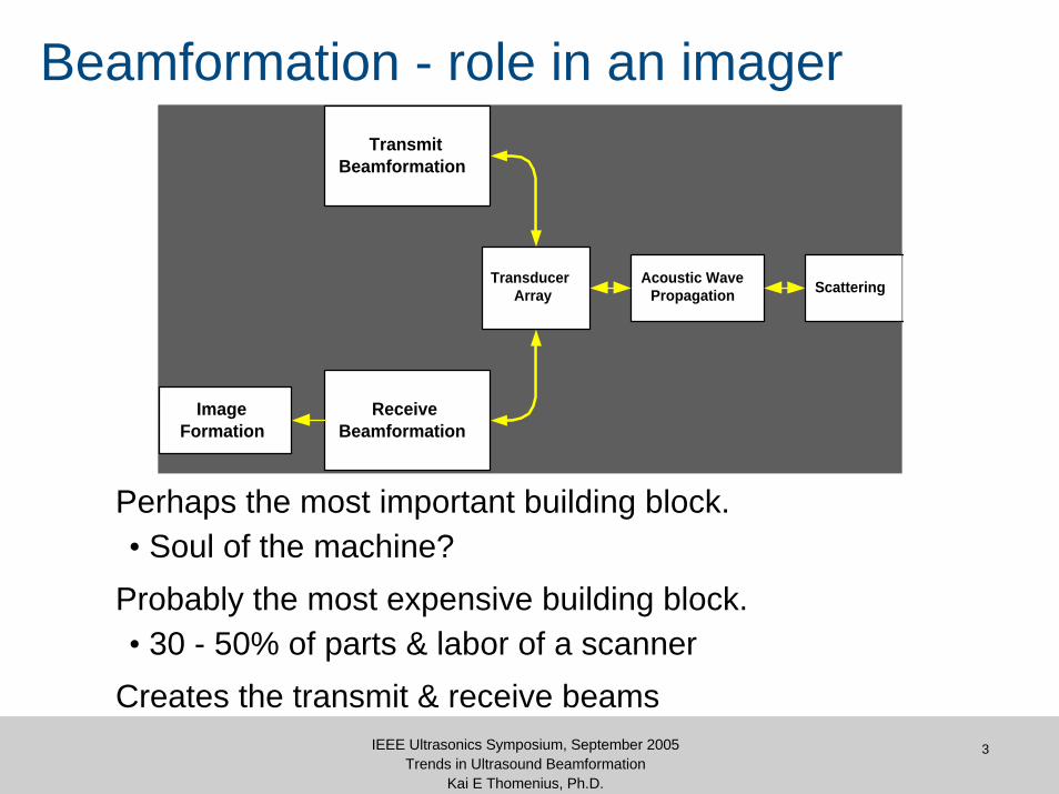
Beamformation - role in an imager
Perhaps the most important building block.• Soul of the machine?
Probably the most expensive building block.• 30 - 50% of parts & labor of a scanner
Creates the transmit & receive beams
TransmitBeamformation
ReceiveBeamformation
TransducerArray
Acoustic WavePropagation Scattering
ImageFormation

4IEEE Ultrasonics Symposium, September 2005Trends in Ultrasound Beamformation
Kai E Thomenius, Ph.D.
Some Beamformer HistoryBefore the mid-70s
• Single element scanners, no beamformer necessary
1975 - 1980• Array based systems
–Linear/curvilinear arrays–Linear phased arrays
• Analog beamformation–Tapped lumped constant delay lines
• Typically 32 channels
Mid 1980s • High channel count systems• High = 128
Early 90s• Digital beamformation
http://www.ob-ultrasound.net/articulated-arm.html
5IEEE Ultrasonics Symposium, September 2005Trends in Ultrasound Beamformation
Kai E Thomenius, Ph.D.
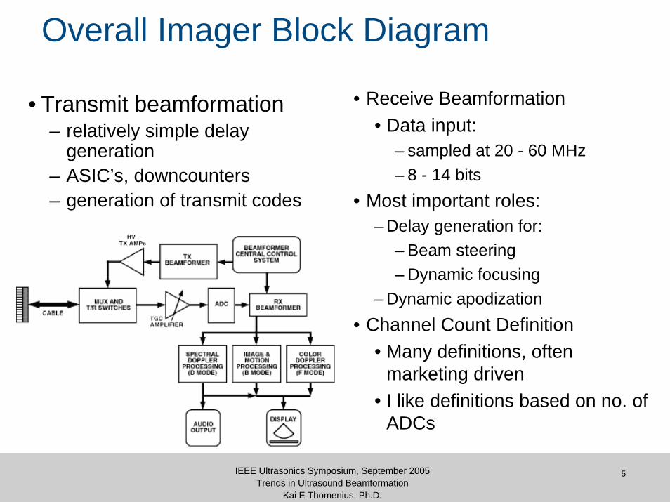
Overall Imager Block Diagram
• Transmit beamformation– relatively simple delay
generation– ASIC’s, downcounters– generation of transmit codes
• Receive Beamformation• Data input:
– sampled at 20 - 60 MHz– 8 - 14 bits
• Most important roles:– Delay generation for:
– Beam steering– Dynamic focusing
– Dynamic apodization• Channel Count Definition
• Many definitions, often marketing driven
• I like definitions based on no. of ADCs
6IEEE Ultrasonics Symposium, September 2005Trends in Ultrasound Beamformation
Kai E Thomenius, Ph.D.
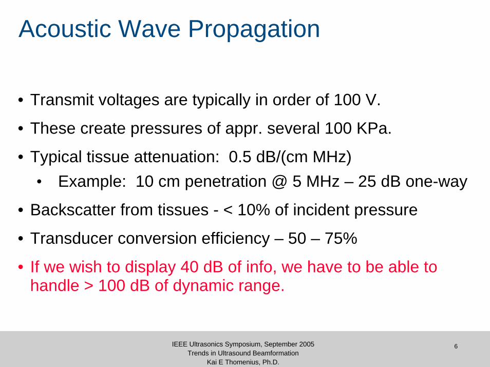
Acoustic Wave Propagation
• Transmit voltages are typically in order of 100 V.
• These create pressures of appr. several 100 KPa.
• Typical tissue attenuation: 0.5 dB/(cm MHz)• Example: 10 cm penetration @ 5 MHz – 25 dB one-way
• Backscatter from tissues - < 10% of incident pressure
• Transducer conversion efficiency – 50 – 75%
• If we wish to display 40 dB of info, we have to be able to handle > 100 dB of dynamic range.

7IEEE Ultrasonics Symposium, September 2005Trends in Ultrasound Beamformation
Kai E Thomenius, Ph.D.
Typical System Organiztion
BEAMFORMER SCANConverter & Display Controller
Doppler Processor
MID PROCESSORS
Color Flow Processor
B Mode Processor
Scan Sequencer
KERNEL
Master Controller
Doppler Processor
MID PROCESSORS
Color Flow Processor
B Mode Processor
System Control Bus (VME (Bus)
Scan Control Bus
Front End Control Bus
OperatorPanel
PROCESSEDVECTORDATA
Doppler SpectGrey 2DColor 2DGrey MColor M
RxSync
TxSync Video Timing
I, Q Data
8IEEE Ultrasonics Symposium, September 2005Trends in Ultrasound Beamformation
Kai E Thomenius, Ph.D.
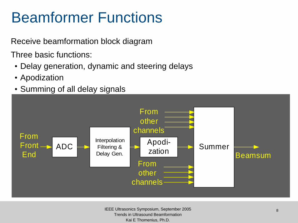
Beamformer FunctionsReceive beamformation block diagramThree basic functions:• Delay generation, dynamic and steering delays• Apodization• Summing of all delay signals
ADCFromFrontEnd
InterpolationFiltering &Delay Gen.
Apodi-zation Summer
Fromother
channels
Fromother
channels
Beamsum
ADCFromFrontEnd
InterpolationFiltering &Delay Gen.
Apodi-zation Summer
Fromother
channels
Fromother
channels
Beamsum
9IEEE Ultrasonics Symposium, September 2005Trends in Ultrasound Beamformation
Kai E Thomenius, Ph.D.
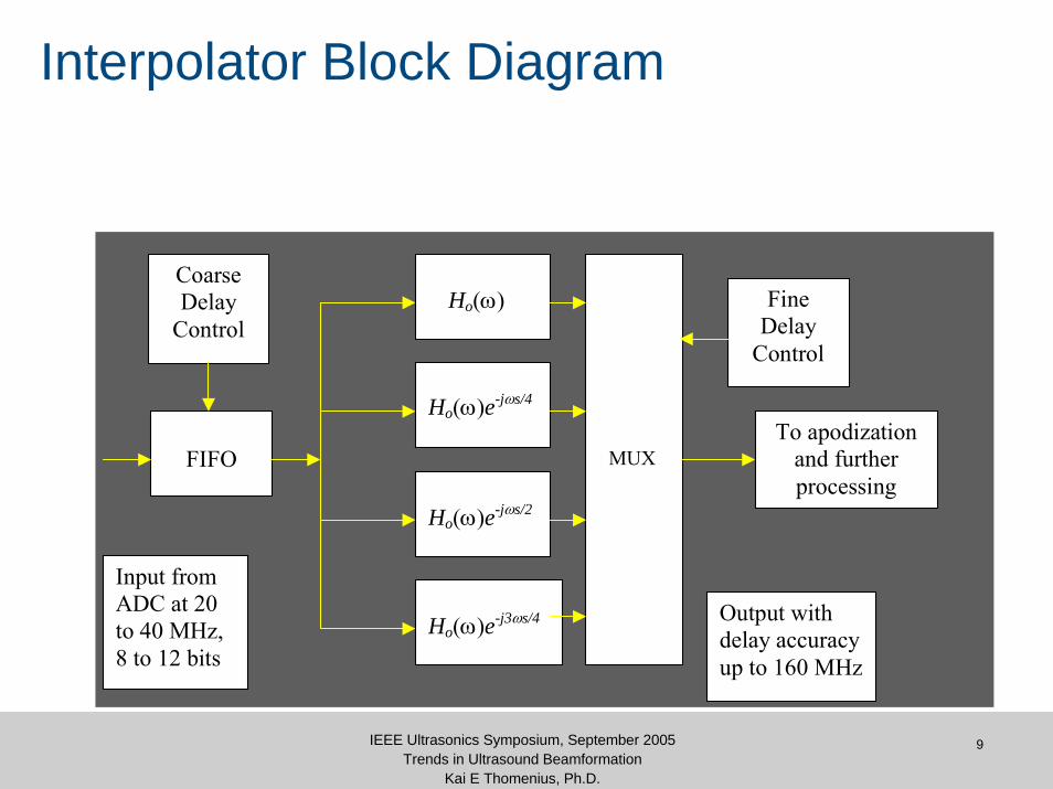
Interpolator Block Diagram
Ho(ω)e-jωs/4
Ho(ω)e-jωs/2
Ho(ω)e-j3ωs/4
Ho(ω)
MUX
FIFO
Input from ADC at 20 to 40 MHz, 8 to 12 bits
Output with delay accuracy up to 160 MHz
To apodization and further processing
Coarse Delay
Control Fine
Delay Control
Beam Manipulations by the Beamformer
11IEEE Ultrasonics Symposium, September 2005Trends in Ultrasound Beamformation
Kai E Thomenius, Ph.D.
-40 -30 -20 -10 0 10 20 30 40
-20
-10
0
10
20
point source
wavefronts before correction
array elements
delay lines
wavefronts after beam steering and focusing
summing stage
Σ
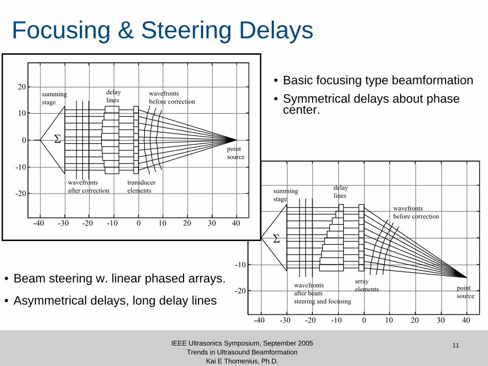
Focusing & Steering Delays
-40 -30 -20 -10 0 10 20 30 40
-20
-10
0
10
20
point source
wavefronts before correction
transducer elements
delay lines
wavefronts after correction
summing stage
Σ
• Basic focusing type beamformation• Symmetrical delays about phase
center.
• Beam steering w. linear phased arrays.
• Asymmetrical delays, long delay lines

12IEEE Ultrasonics Symposium, September 2005Trends in Ultrasound Beamformation
Kai E Thomenius, Ph.D.
Transmit Vectors and Focal Zones
Multiple transmit focal zones
Image formation using transmits along vectors and focal zones
Transmit vector
13IEEE Ultrasonics Symposium, September 2005Trends in Ultrasound Beamformation
Kai E Thomenius, Ph.D.
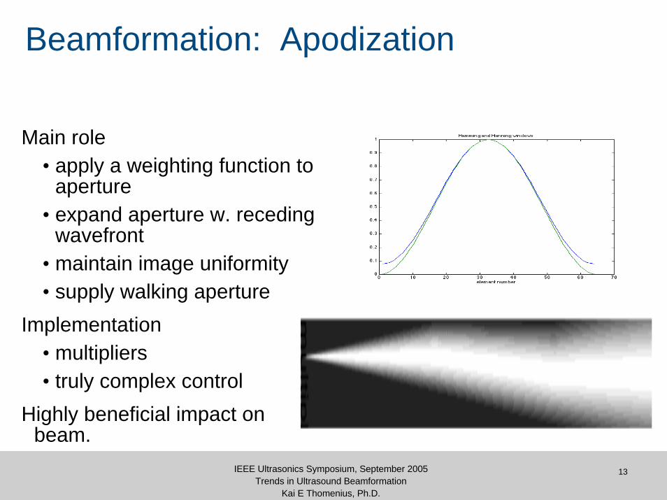
Beamformation: Apodization
Main role• apply a weighting function to
aperture• expand aperture w. receding
wavefront• maintain image uniformity• supply walking aperture
Implementation• multipliers• truly complex control
Highly beneficial impact on beam.
14IEEE Ultrasonics Symposium, September 2005Trends in Ultrasound Beamformation
Kai E Thomenius, Ph.D.
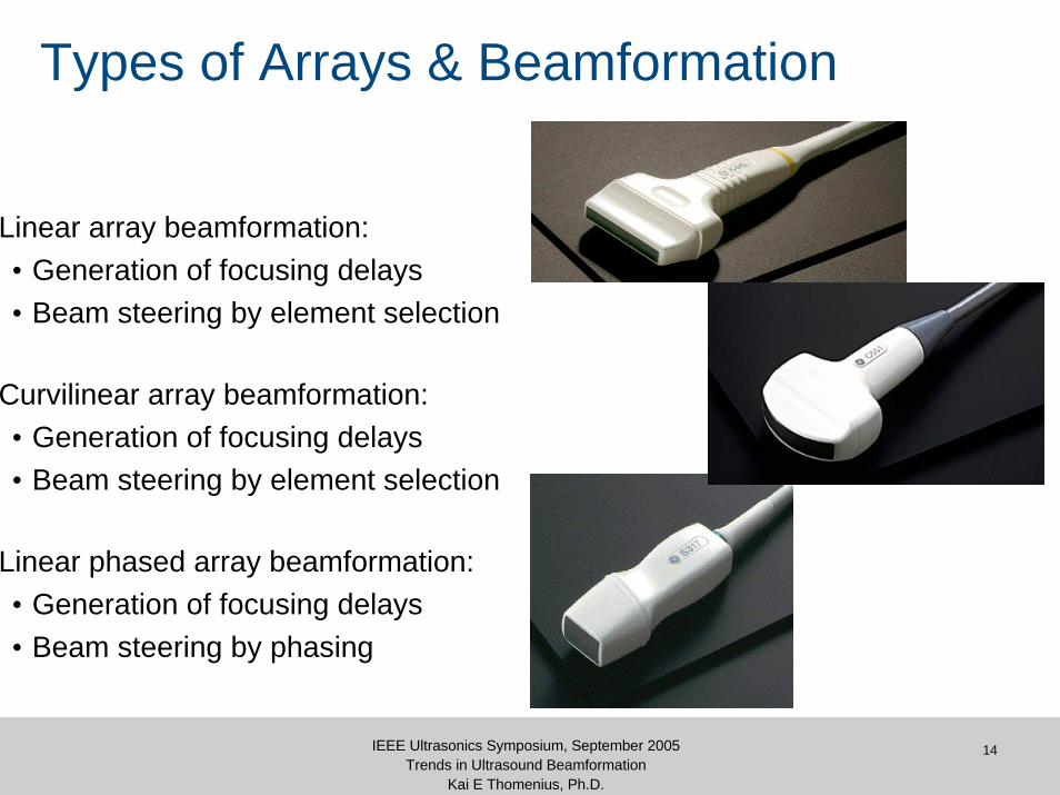
Types of Arrays & Beamformation
Linear array beamformation:• Generation of focusing delays• Beam steering by element selection
Curvilinear array beamformation:• Generation of focusing delays• Beam steering by element selection
Linear phased array beamformation:• Generation of focusing delays• Beam steering by phasing
15IEEE Ultrasonics Symposium, September 2005Trends in Ultrasound Beamformation
Kai E Thomenius, Ph.D.
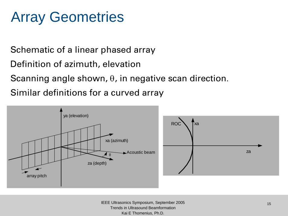
Array Geometries
Schematic of a linear phased array
Definition of azimuth, elevation
Scanning angle shown, θ, in negative scan direction.
Similar definitions for a curved array
ya (elevation)
xa (azimuth)
za (depth)
array pitch
Acoustic beamθ
xa
za
ROC

16IEEE Ultrasonics Symposium, September 2005Trends in Ultrasound Beamformation
Kai E Thomenius, Ph.D.
Some Basic Geometry
Delay determination:• simple path length difference• reference point: phase center• apply Law of Cosines• approximate for ASIC
implementation
In some cases, split delay into 2 parts:• beam steering• dynamic focusing
x
z
xr,θ
r
0
rx
crr x−
=τ
( )[ ]rrrxxc
−+−= 22 sin21 θτ
fs τ+τ=τ
17IEEE Ultrasonics Symposium, September 2005Trends in Ultrasound Beamformation
Kai E Thomenius, Ph.D.
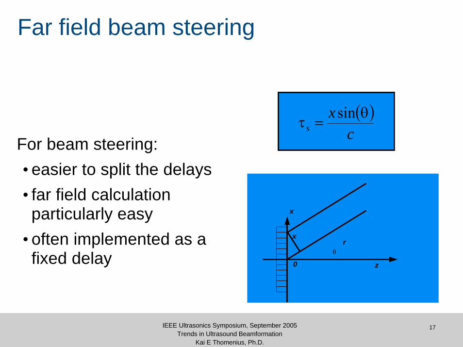
Far field beam steering
For beam steering:• easier to split the delays• far field calculation particularly easy
• often implemented as a fixed delay
( )c
xs
θ=τ
sin
x
z
xr
0θ
18IEEE Ultrasonics Symposium, September 2005Trends in Ultrasound Beamformation
Kai E Thomenius, Ph.D.
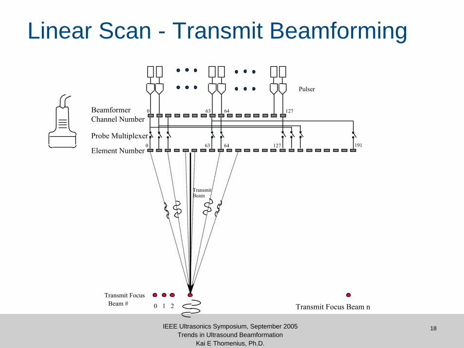
Linear Scan - Transmit Beamforming
Transmit Focus
1
Transmit Beam
2 Transmit Focus Beam nBeam # 0
Pulser
BeamformerChannel Number
0 12763 191
0 12763
Element Number
Probe Multiplexer
64
64

19IEEE Ultrasonics Symposium, September 2005Trends in Ultrasound Beamformation
Kai E Thomenius, Ph.D.
Beamformation: the movie
20IEEE Ultrasonics Symposium, September 2005Trends in Ultrasound Beamformation
Kai E Thomenius, Ph.D.
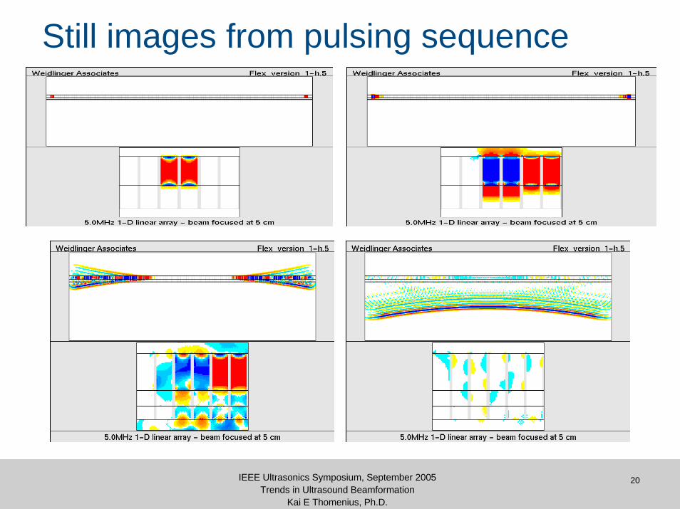
Still images from pulsing sequence
21IEEE Ultrasonics Symposium, September 2005Trends in Ultrasound Beamformation
Kai E Thomenius, Ph.D.

22IEEE Ultrasonics Symposium, September 2005Trends in Ultrasound Beamformation
Kai E Thomenius, Ph.D.
Resolution / Penetration DilemmaTransmit Energy Determines Penetration
PulseAmplitude
Mechanical Index Limit
Pulse LengthLonger pulse gains penetration but
sacrifices resolution
23IEEE Ultrasonics Symposium, September 2005Trends in Ultrasound Beamformation
Kai E Thomenius, Ph.D.
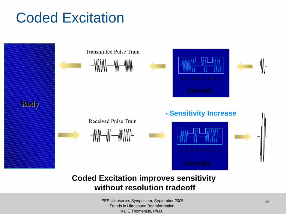
Coded Excitation
Decoder
• Sensitivity Increase
Encoder
1 1 1 0 1 0 1 1
Coded Excitation improves sensitivity without resolution tradeoff
Received Pulse Train
1 1 0 1 0 1 1 1
BodyBody
Transmitted Pulse Train

24IEEE Ultrasonics Symposium, September 2005Trends in Ultrasound Beamformation
Kai E Thomenius, Ph.D.
Coded Excitation - Experiment
High FrequencyHigh Frequency
18 cm
15 cm
Improve penetration by 3 cm with same resolution to -50 dB
Coded ExcitationCoded Excitation
25IEEE Ultrasonics Symposium, September 2005Trends in Ultrasound Beamformation
Kai E Thomenius, Ph.D.
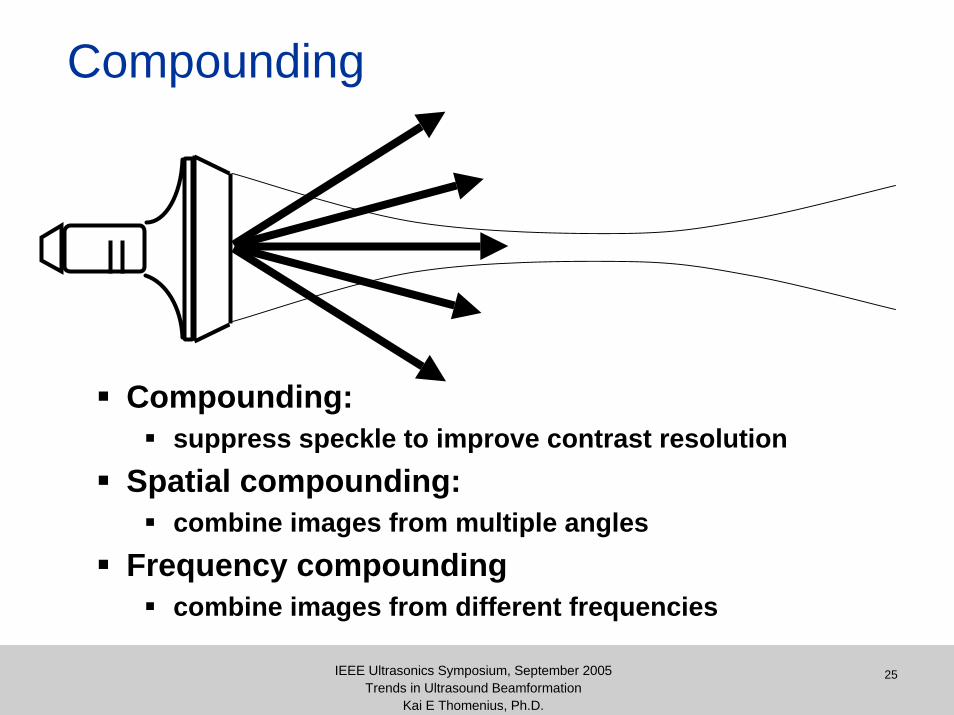
Compounding
Compounding:suppress speckle to improve contrast resolution
Spatial compounding:combine images from multiple angles
Frequency compoundingcombine images from different frequencies
26IEEE Ultrasonics Symposium, September 2005Trends in Ultrasound Beamformation
Kai E Thomenius, Ph.D.
What are we trying to image?Medical ultrasound different from radar.• volume scatterers• very wide band• near field
First level• Gross anatomy• basic measurements
– e.g. fetal dimensions• often tissue/fluid interfaces• not very challenging
Second level• soft tissue characteristics
– attenuation– speckle size
• minimum acoustic noise• beam performance critical
Third level• 3D/4D volume & surface
rendering• Beam performance critical
27IEEE Ultrasonics Symposium, September 2005Trends in Ultrasound Beamformation
Kai E Thomenius, Ph.D.
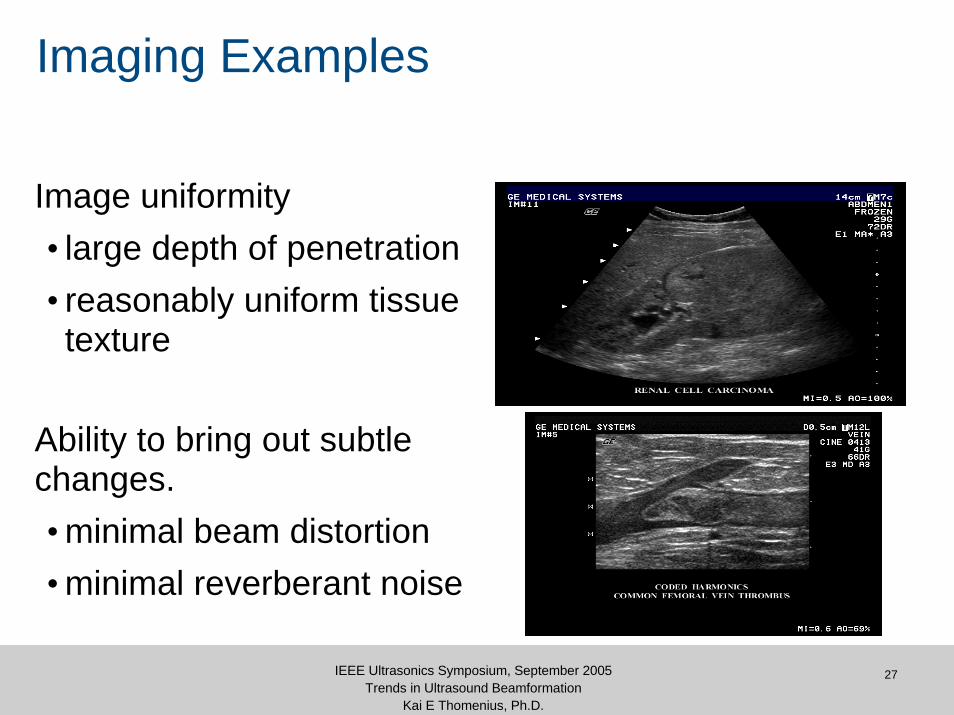
Imaging Examples
Image uniformity• large depth of penetration• reasonably uniform tissue texture
Ability to bring out subtle changes.• minimal beam distortion• minimal reverberant noise

Beamshapes, Focusing, and all that

29IEEE Ultrasonics Symposium, September 2005Trends in Ultrasound Beamformation
Kai E Thomenius, Ph.D.
Anatomy of an ultrasound beam
Near field or Fresnel zone
Far field or Fraunhofer zone
Near-to-far field transition, L
λ=
4
2DL
30IEEE Ultrasonics Symposium, September 2005Trends in Ultrasound Beamformation
Kai E Thomenius, Ph.D.
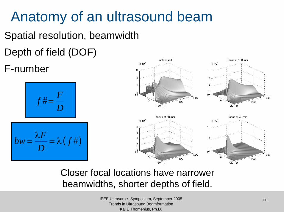
Anatomy of an ultrasound beamSpatial resolution, beamwidthDepth of field (DOF)F-number
DFf =#
( )#fDFbw λ=
λ=
Closer focal locations have narrower beamwidths, shorter depths of field.
31IEEE Ultrasonics Symposium, September 2005Trends in Ultrasound Beamformation
Kai E Thomenius, Ph.D.
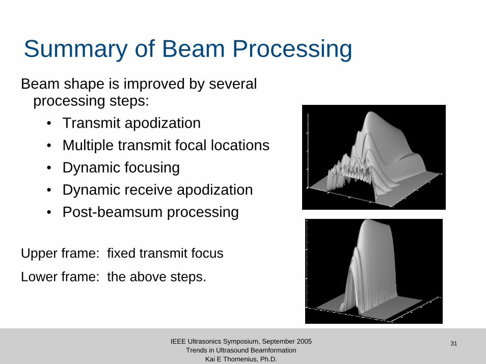
Summary of Beam ProcessingBeam shape is improved by several
processing steps:• Transmit apodization• Multiple transmit focal locations• Dynamic focusing• Dynamic receive apodization• Post-beamsum processing
Upper frame: fixed transmit focus
Lower frame: the above steps.
32IEEE Ultrasonics Symposium, September 2005Trends in Ultrasound Beamformation
Kai E Thomenius, Ph.D.
Analysis of beamformation
Basic narrowband far-field analysis• radar type analysis
Spatial impulse response method•application to regulatory measurements
Angular spectrum methods•propagation of beams•harmonic imaging
Narrow-band Far Field Analysis
34IEEE Ultrasonics Symposium, September 2005Trends in Ultrasound Beamformation
Kai E Thomenius, Ph.D.
Narrowband far-field analysis
Totally unrealistic model
Amazingly useful results
will be used to introduce key points
35IEEE Ultrasonics Symposium, September 2005Trends in Ultrasound Beamformation
Kai E Thomenius, Ph.D.
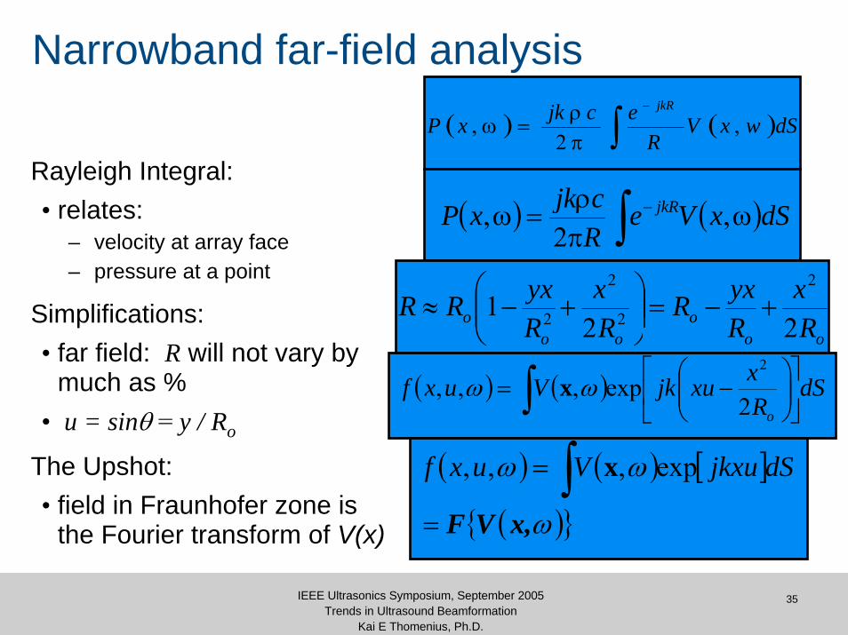
Narrowband far-field analysis
Rayleigh Integral:• relates:
– velocity at array face– pressure at a point
Simplifications:• far field: R will not vary by
much as %• u = sinθ = y / Ro
The Upshot:• field in Fraunhofer zone is
the Fourier transform of V(x)
( ) ( )∫−
πρ
=ω dSwxVR
ecjkxPjkR
,2
,
( ) ( )∫ ωπρ
=ω − dSxVeRcjkxP jkR ,
2,
ooo
ooo R
xRyxR
Rx
RyxRR
221
2
2
2
2 +−=⎟⎟⎠
⎞⎜⎜⎝
⎛+−≈
( ) ( )∫ ⎥⎦
⎤⎢⎣
⎡⎟⎟⎠
⎞⎜⎜⎝
⎛−= dS
RxxujkVuxf
o2exp,,,
2
ωω x
( ) ( ) [ ]
( ){ }ω
ωω
x,VF=
= ∫ dSjkxuVuxf exp,,, x
36IEEE Ultrasonics Symposium, September 2005Trends in Ultrasound Beamformation
Kai E Thomenius, Ph.D.
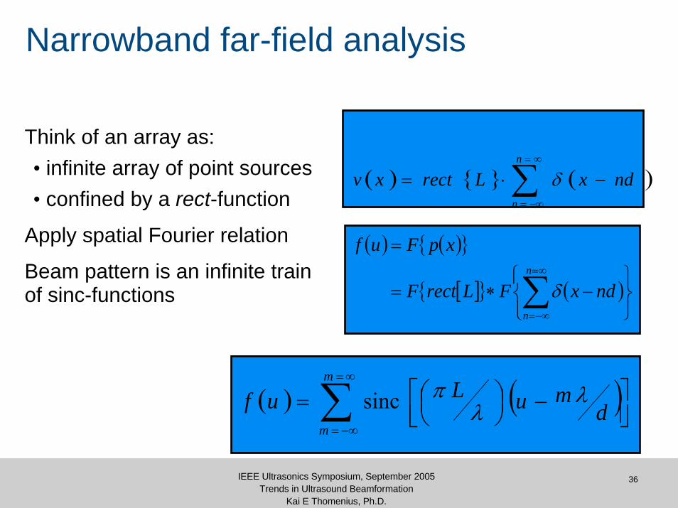
Narrowband far-field analysis
Think of an array as:• infinite array of point sources• confined by a rect-function
Apply spatial Fourier relation
Beam pattern is an infinite train of sinc-functions
( ) { } ( )∑∞=
−∞=
−⋅=n
n
ndxLrectxv δ
( ) ( ){ }
[ ]{ } ( )⎭⎬⎫
⎩⎨⎧
−∗=
=
∑∞=
−∞=
n
n
ndxFLrectF
xpFuf
δ
( ) ( )∑∞=
−∞=⎥⎦⎤
⎢⎣⎡ −⎟
⎠⎞⎜
⎝⎛=
m
md
muLuf λλ
πsinc
37IEEE Ultrasonics Symposium, September 2005Trends in Ultrasound Beamformation
Kai E Thomenius, Ph.D.
Narrowband far-field analysis
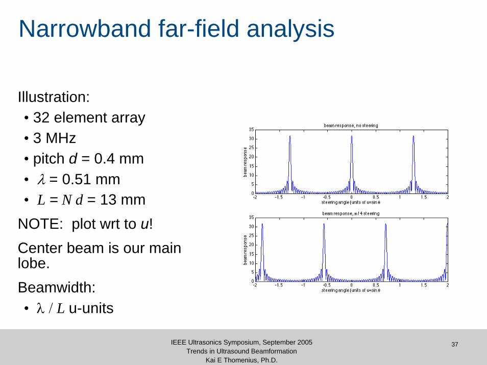
Illustration:• 32 element array• 3 MHz• pitch d = 0.4 mm• λ = 0.51 mm• L = N d = 13 mm
NOTE: plot wrt to u!Center beam is our main lobe.Beamwidth:• λ / L u-units

38IEEE Ultrasonics Symposium, September 2005Trends in Ultrasound Beamformation
Kai E Thomenius, Ph.D.
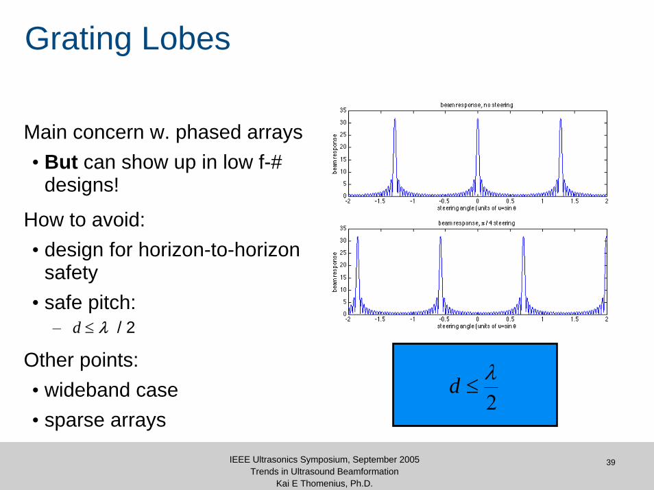
Narrowband far-field analysis
Adjacent beams:• grating lobes
Separation:• λ / d u-units
Beam steering:• apply τs phase tilt
Danger!• Grating lobes move w.
main
Visible region:• ±0.707 u-units or ±45
degrees
( )c
xs
θ=τ
sin
39IEEE Ultrasonics Symposium, September 2005Trends in Ultrasound Beamformation
Kai E Thomenius, Ph.D.
Grating Lobes
Main concern w. phased arrays• But can show up in low f-#
designs!
How to avoid:• design for horizon-to-horizon
safety• safe pitch:
– d ≤ λ / 2
Other points:• wideband case• sparse arrays
2λ
≤d

40IEEE Ultrasonics Symposium, September 2005Trends in Ultrasound Beamformation
Kai E Thomenius, Ph.D.
Apodization
Same array:• 32 element array• 3 MHz• pitch d = 0.4 mm• λ = 0.51 mm• L = N d = 13 mm
With & w/o Hanning wting.
Sidelobes way down.
No effect on grating lobes.
41IEEE Ultrasonics Symposium, September 2005Trends in Ultrasound Beamformation
Kai E Thomenius, Ph.D.
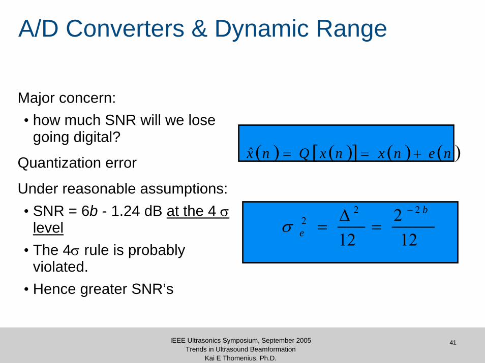
A/D Converters & Dynamic Range
Major concern:• how much SNR will we lose
going digital?
Quantization error
Under reasonable assumptions:• SNR = 6b - 1.24 dB at the 4 σ
level• The 4σ rule is probably
violated.• Hence greater SNR’s
( ) ( )[ ] ( ) ( )nenxnxQnx +==ˆ
122
12
222
b
e
−
=Δ
=σ
More Realistic Simulations
43IEEE Ultrasonics Symposium, September 2005Trends in Ultrasound Beamformation
Kai E Thomenius, Ph.D.
More Realistic Models
Far field, narrow band models are useful, though not very realistic.We will discuss two types of models which come closer to reality:• Spatial Impulse Response
– Approach used in Field II code
• Angular Spectrum And some examples of each.

44IEEE Ultrasonics Symposium, September 2005Trends in Ultrasound Beamformation
Kai E Thomenius, Ph.D.
Spatial Impulse Response
Velocity Potential• particle velocity as gradient of a scalar
• u(x,y,z) = grad(φ(x,y,z))Such functions readily available.φ(x,y,z,t) written as a convolution.This has led to the concept of spatial impulse response.
( ) ∫ −
⎟⎟⎠
⎞⎜⎜⎝
⎛ −−
=S
n
dSrrc
rrtrv
t21
212
2
,, rr
rr
r
πφ r
( ) ( ) ∫ −
⎟⎟⎠
⎞⎜⎜⎝
⎛ −−−
∗=S
n dSrrc
rrtt
tvt21
212
2, rr
rr
r
π
δφ r
( ) ∫ −
⎟⎠⎞
⎜⎝⎛ −
−=
SdS
rrc
rrt
trh21
21
1 2, rr
rr
r
π
δ
45IEEE Ultrasonics Symposium, September 2005Trends in Ultrasound Beamformation
Kai E Thomenius, Ph.D.
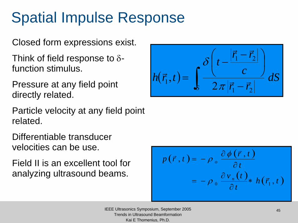
Spatial Impulse ResponseClosed form expressions exist.
Think of field response to δ-function stimulus.
Pressure at any field point directly related.
Particle velocity at any field point related.
Differentiable transducer velocities can be use.
Field II is an excellent tool for analyzing ultrasound beams.
( ) ∫ −
⎟⎠⎞
⎜⎝⎛ −
−=
SdS
rrc
rrt
trh21
21
1 2, rr
rr
r
π
δ
( ) ( )
( ) ( )trht
tvt
trtrp
n
o
,
,,
10r
rr
∗∂
∂−=
∂∂
−=
ρ
φρ
46IEEE Ultrasonics Symposium, September 2005Trends in Ultrasound Beamformation
Kai E Thomenius, Ph.D.
Spatial Impulse Response: Testing
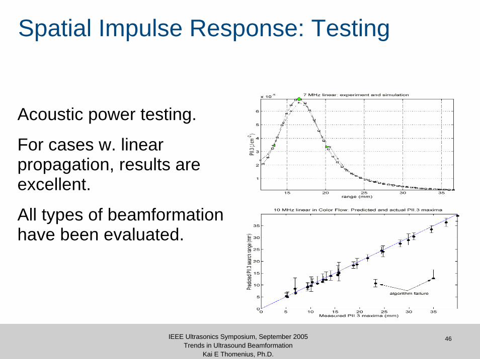
Acoustic power testing.
For cases w. linear propagation, results are excellent.
All types of beamformation have been evaluated.
47IEEE Ultrasonics Symposium, September 2005Trends in Ultrasound Beamformation
Kai E Thomenius, Ph.D.
Angular Spectrum Method
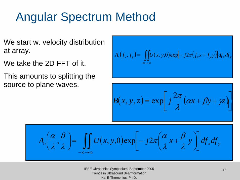
We start w. velocity distribution at array.
We take the 2D FFT of it.
This amounts to splitting the source to plane waves.
( ) ( ) ( )[ ]∫∫∞→∞−
+−= yxyxyxo dfdfyfxfjyxUffA π2exp0,,,
( ) ( )⎥⎦⎤
⎢⎣⎡ ++= zyxjzyxB γβα
λπ2exp,,
( )∫∫∞→∞−
⎥⎦⎤
⎢⎣⎡
⎟⎠⎞
⎜⎝⎛ +−=⎟
⎠⎞
⎜⎝⎛
yxo dfdfyxjyxUAλβ
λαπ
λβ
λα 2exp0,,,
48IEEE Ultrasonics Symposium, September 2005Trends in Ultrasound Beamformation
Kai E Thomenius, Ph.D.
Angular Spectrum Method
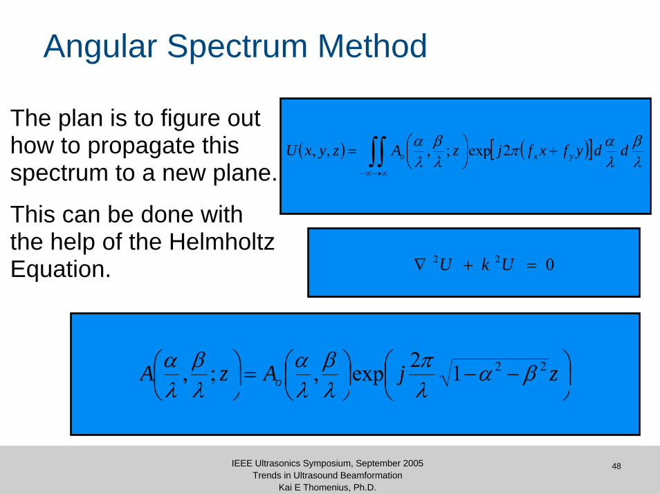
The plan is to figure out how to propagate this spectrum to a new plane.
This can be done with the help of the Helmholtz Equation.
( ) ( )[ ]∫∫∞→∞−
+⎟⎠⎞
⎜⎝⎛=
λβ
λαπ
λβ
λα ddyfxfjzAzyxU yxo 2exp;,,,
⎟⎠⎞
⎜⎝⎛ −−⎟
⎠⎞
⎜⎝⎛=⎟
⎠⎞
⎜⎝⎛ zjAzA o
2212exp,;, βαλπ
λβ
λα
λβ
λα
022 =+∇ UkU
49IEEE Ultrasonics Symposium, September 2005Trends in Ultrasound Beamformation
Kai E Thomenius, Ph.D.
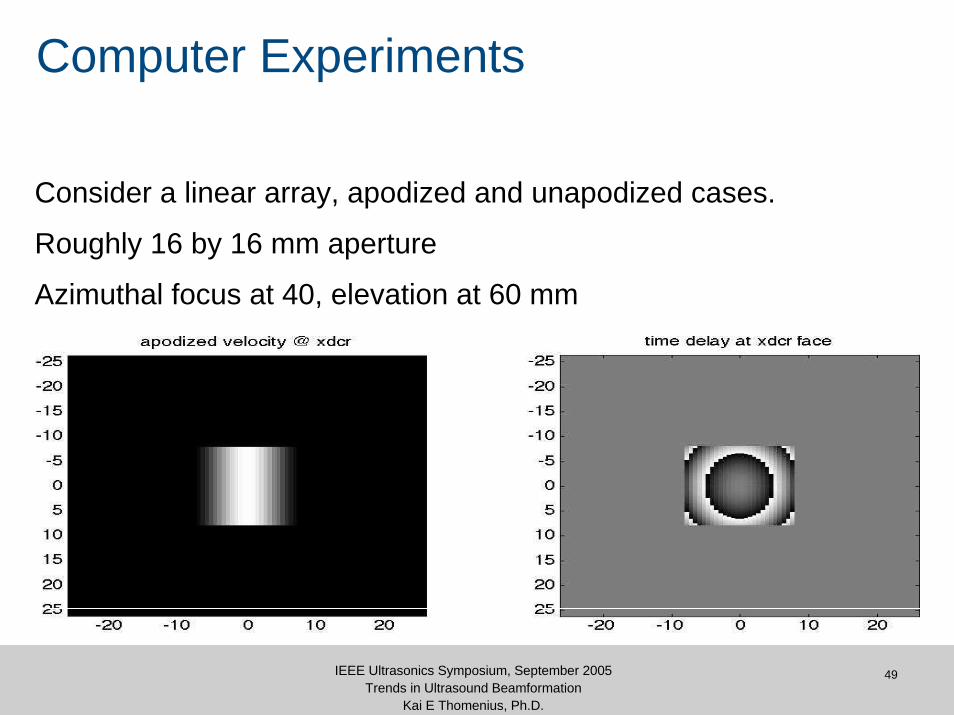
Computer Experiments
Consider a linear array, apodized and unapodized cases.
Roughly 16 by 16 mm aperture
Azimuthal focus at 40, elevation at 60 mm
50IEEE Ultrasonics Symposium, September 2005Trends in Ultrasound Beamformation
Kai E Thomenius, Ph.D.
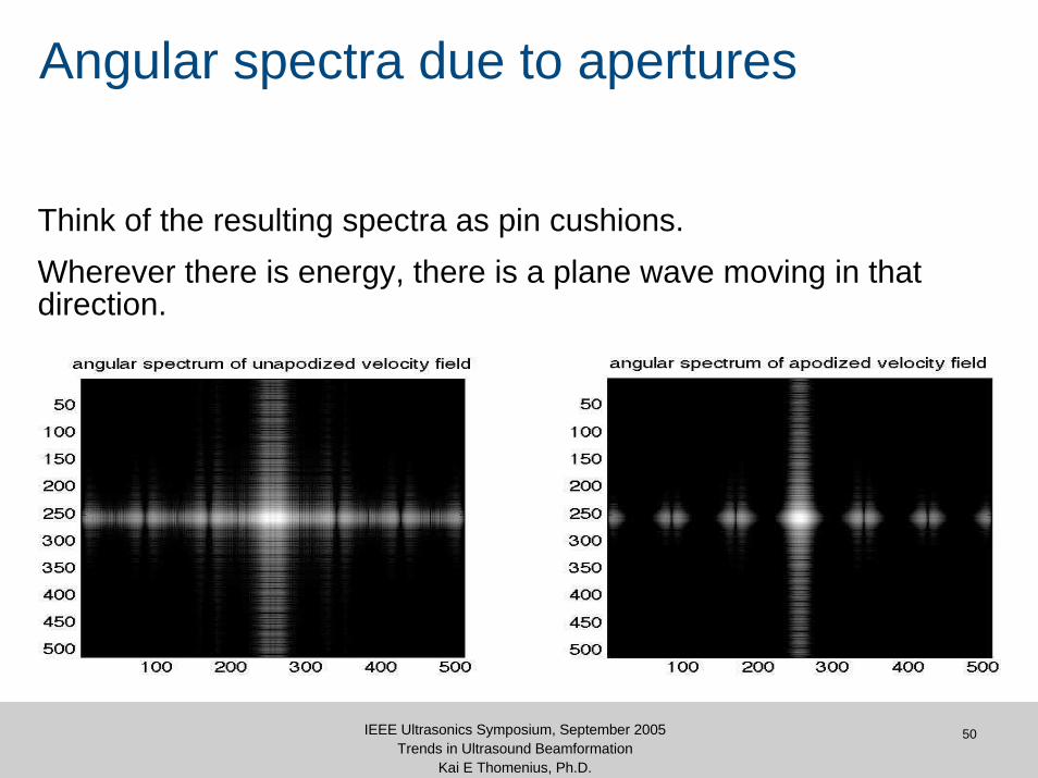
Angular spectra due to apertures
Think of the resulting spectra as pin cushions.Wherever there is energy, there is a plane wave moving in that direction.

51IEEE Ultrasonics Symposium, September 2005Trends in Ultrasound Beamformation
Kai E Thomenius, Ph.D.
Propagation of Beam from Array
52IEEE Ultrasonics Symposium, September 2005Trends in Ultrasound Beamformation
Kai E Thomenius, Ph.D.
Movie of Propagating Beam
53IEEE Ultrasonics Symposium, September 2005Trends in Ultrasound Beamformation
Kai E Thomenius, Ph.D.
Utility of Models
Why bother?• Beamformer design validation before going to hardware.– How good a beam results from the design choices made?– New modes (RT3D) and new instruments (laptop ultrasound)
• Reduction of regulatory measurement work load.• Analysis of new topics such as:
– contrast agent performance– harmonic imaging.– aberration correction
54IEEE Ultrasonics Symposium, September 2005Trends in Ultrasound Beamformation
Kai E Thomenius, Ph.D.
Recent Advances in Simulation
Much of the work reported has been done with finite difference methods.
These are limited in their ability to estimate the derivatives.
Improvements exist mainly with FFT estimation of derivatives:• pseudospectral methods (Weidlinger)
– example: previous transducer/beam movie
• k-space methods (U. of Rochester)– examples to be shown.

55IEEE Ultrasonics Symposium, September 2005Trends in Ultrasound Beamformation
Kai E Thomenius, Ph.D.
Sound propagation in water
56IEEE Ultrasonics Symposium, September 2005Trends in Ultrasound Beamformation
Kai E Thomenius, Ph.D.
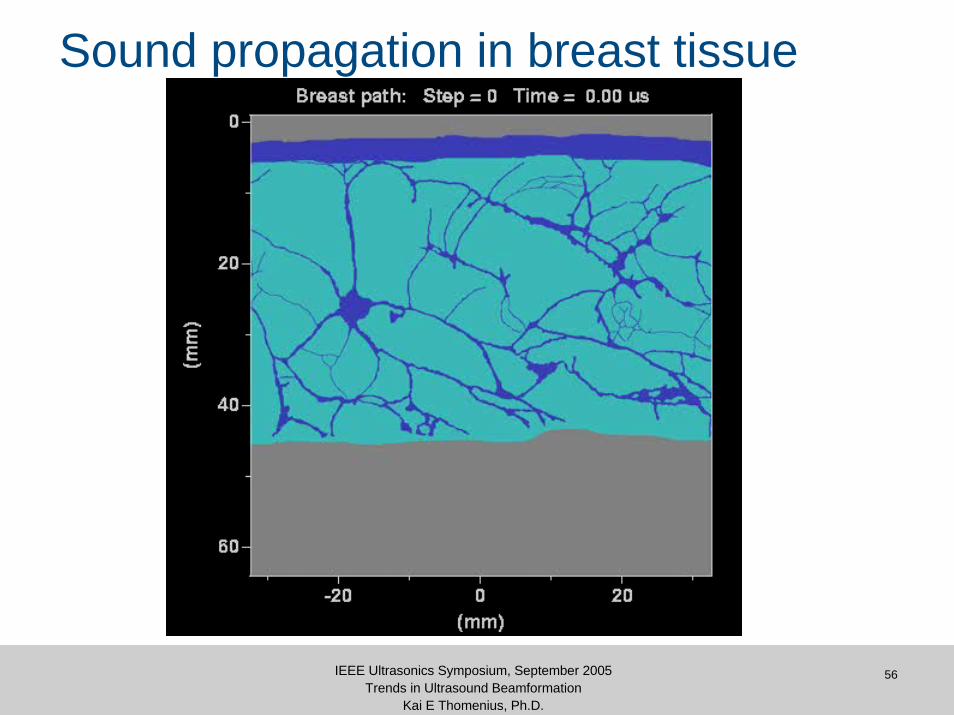
Sound propagation in breast tissue
57IEEE Ultrasonics Symposium, September 2005Trends in Ultrasound Beamformation
Kai E Thomenius, Ph.D.
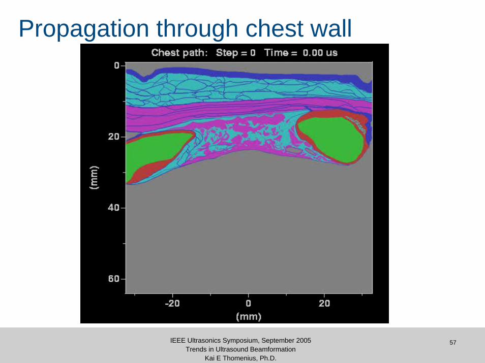
Propagation through chest wall

Harmonic Imaging
59IEEE Ultrasonics Symposium, September 2005Trends in Ultrasound Beamformation
Kai E Thomenius, Ph.D.
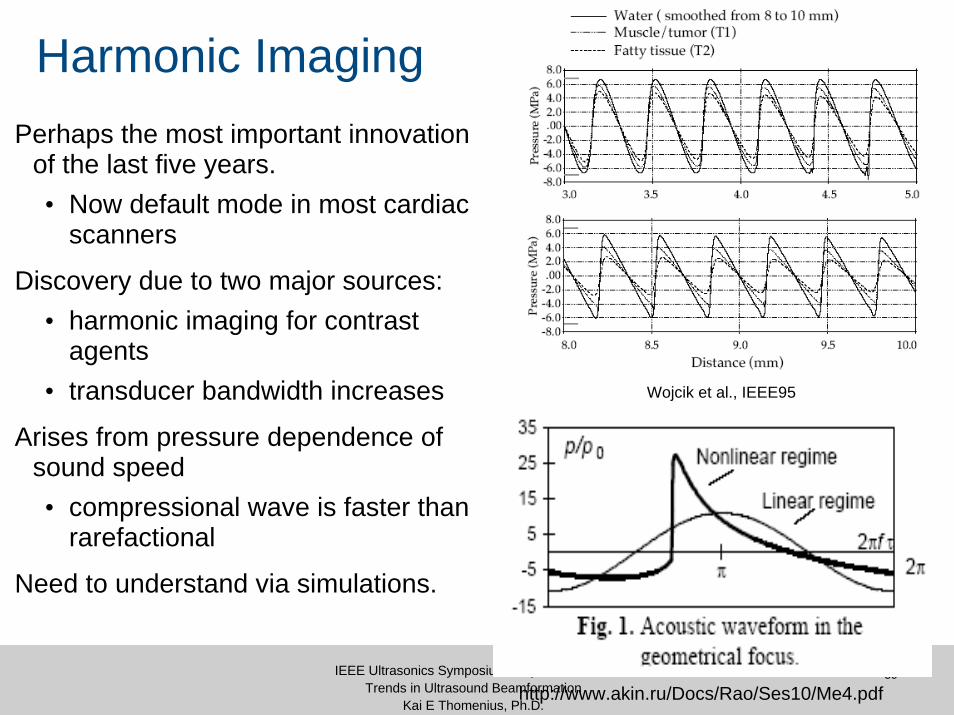
Harmonic ImagingPerhaps the most important innovation
of the last five years.• Now default mode in most cardiac
scanners
Discovery due to two major sources:• harmonic imaging for contrast
agents• transducer bandwidth increases
Arises from pressure dependence of sound speed • compressional wave is faster than
rarefactional
Need to understand via simulations.
http://www.akin.ru/Docs/Rao/Ses10/Me4.pdf
Wojcik et al., IEEE95
60IEEE Ultrasonics Symposium, September 2005Trends in Ultrasound Beamformation
Kai E Thomenius, Ph.D.
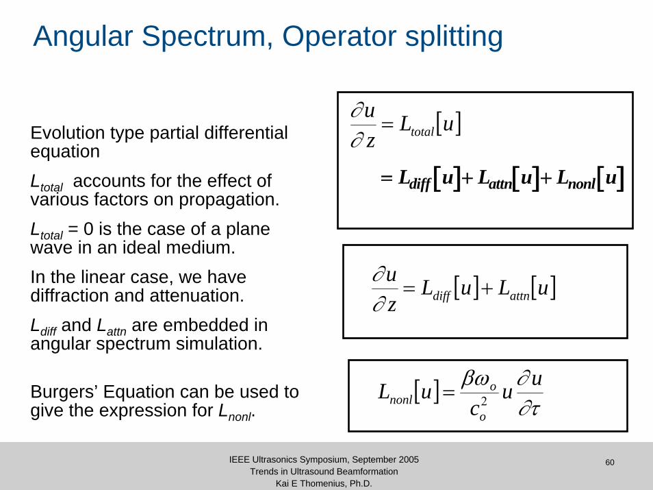
Angular Spectrum, Operator splitting
Evolution type partial differential equationLtotal accounts for the effect of various factors on propagation.Ltotal = 0 is the case of a plane wave in an ideal medium.In the linear case, we have diffraction and attenuation.Ldiff and Lattn are embedded in angular spectrum simulation.
Burgers’ Equation can be used to give the expression for Lnonl.
[ ] [ ] [ ]= + +L u L u L udiff attn nonl
[ ]uLzu
total=∂∂
[ ] [ ]uLuLzu
attndiff +=∂∂
[ ]∂τ∂βω uu
cuL
o
ononl 2=
61IEEE Ultrasonics Symposium, September 2005Trends in Ultrasound Beamformation
Kai E Thomenius, Ph.D.
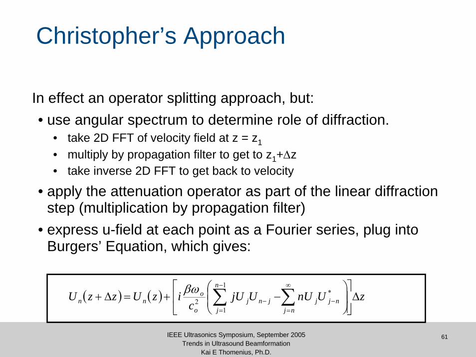
Christopher’s Approach
In effect an operator splitting approach, but:• use angular spectrum to determine role of diffraction.
• take 2D FFT of velocity field at z = z1
• multiply by propagation filter to get to z1+Δz• take inverse 2D FFT to get back to velocity
• apply the attenuation operator as part of the linear diffractionstep (multiplication by propagation filter)
• express u-field at each point as a Fourier series, plug into Burgers’ Equation, which gives:
( ) ( ) zUnUUjUc
izUzzUnj
njj
n
jjnj
o
onn Δ
⎥⎥⎦
⎤
⎢⎢⎣
⎡⎟⎟⎠
⎞⎜⎜⎝
⎛−+=Δ+ ∑∑
∞
=−
−
=−
*1
12
βω
62IEEE Ultrasonics Symposium, September 2005Trends in Ultrasound Beamformation
Kai E Thomenius, Ph.D.
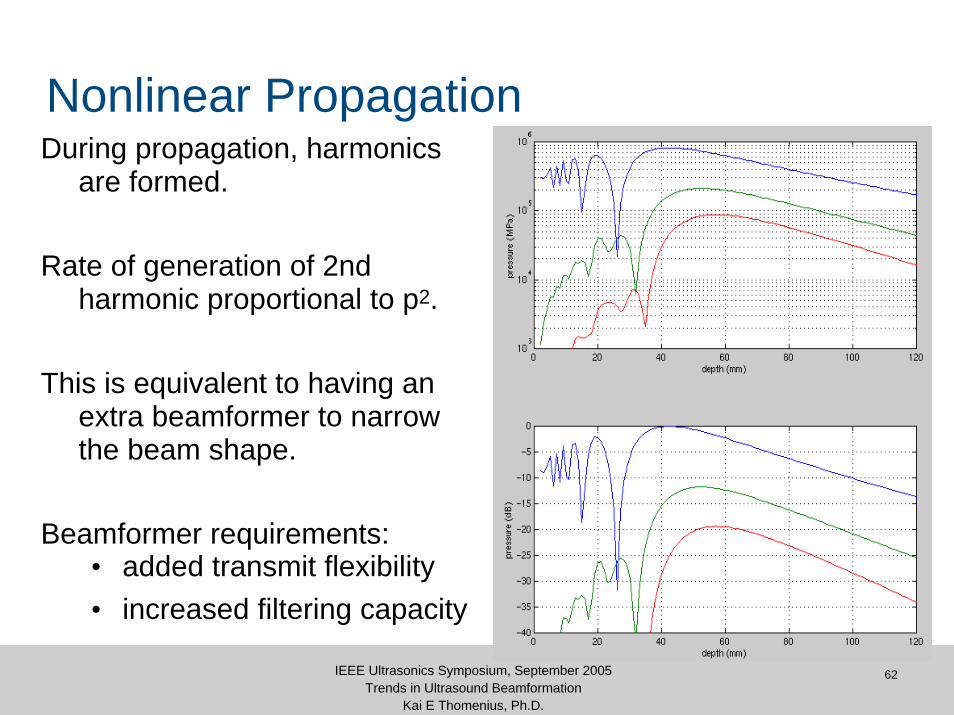
Nonlinear PropagationDuring propagation, harmonics
are formed.
Rate of generation of 2nd harmonic proportional to p2.
This is equivalent to having an extra beamformer to narrow the beam shape.
Beamformer requirements:• added transmit flexibility• increased filtering capacity
63IEEE Ultrasonics Symposium, September 2005Trends in Ultrasound Beamformation
Kai E Thomenius, Ph.D.
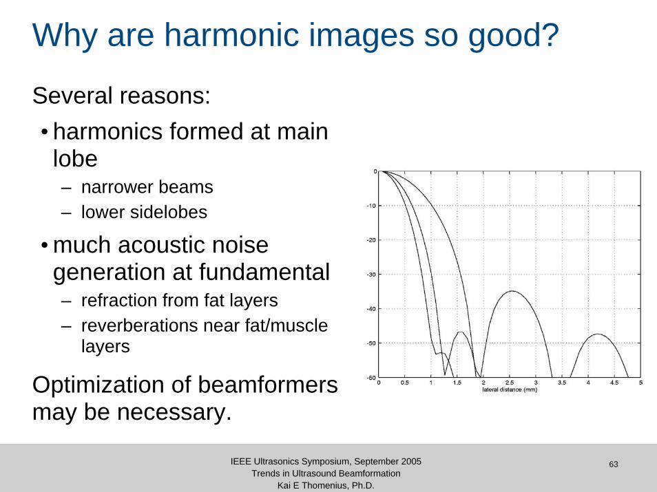
Why are harmonic images so good?
Several reasons:• harmonics formed at main lobe– narrower beams– lower sidelobes
• much acoustic noise generation at fundamental– refraction from fat layers– reverberations near fat/muscle
layers
Optimization of beamformers may be necessary.
64IEEE Ultrasonics Symposium, September 2005Trends in Ultrasound Beamformation
Kai E Thomenius, Ph.D.
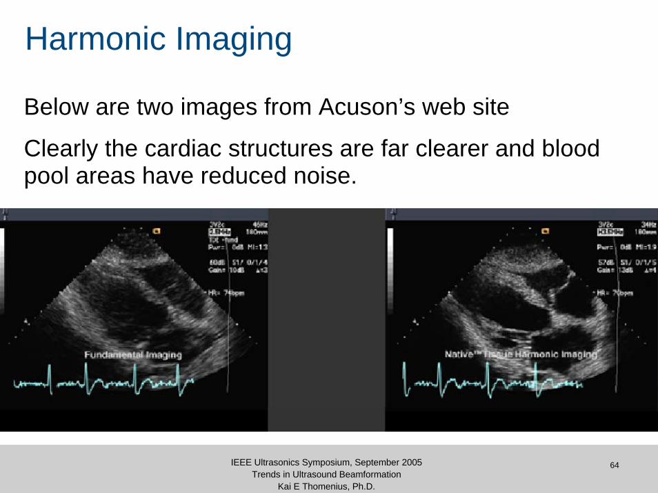
Harmonic Imaging
Below are two images from Acuson’s web site
Clearly the cardiac structures are far clearer and blood pool areas have reduced noise.
65IEEE Ultrasonics Symposium, September 2005Trends in Ultrasound Beamformation
Kai E Thomenius, Ph.D.
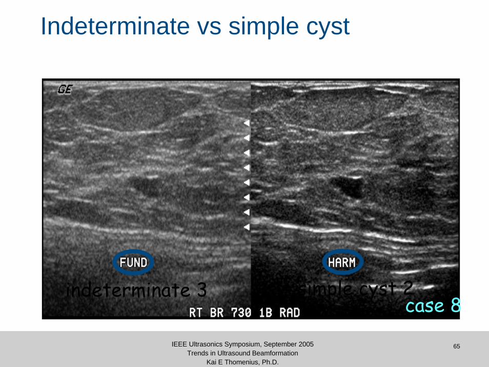
Indeterminate vs simple cyst
indeterminate 3 simple cyst 2case 8
66IEEE Ultrasonics Symposium, September 2005Trends in Ultrasound Beamformation
Kai E Thomenius, Ph.D.
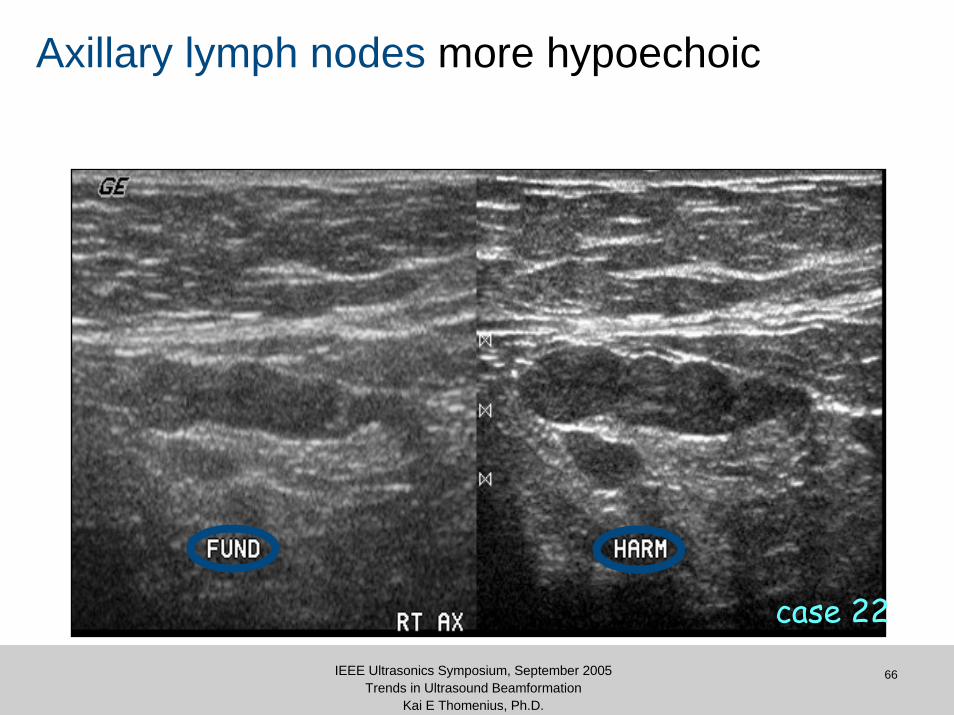
Axillary lymph nodes more hypoechoic
case 22

67IEEE Ultrasonics Symposium, September 2005Trends in Ultrasound Beamformation
Kai E Thomenius, Ph.D.
BI-RADS codes fundamental / harmonics
1 2 3 4a 4b 5fundamental
010203040506070
num
ber
of c
ases
BIRADS codes
fundamentalharmonics
47%
35%
17%29%
8%7%

68IEEE Ultrasonics Symposium, September 2005Trends in Ultrasound Beamformation
Kai E Thomenius, Ph.D.
Contrast Agent Harmonic Imaging
Ultrasound contrast• Gas filled microbubbles• Strong harmonic response• Main clinical goal: perfusion
– Myocardial viability– Presence of tumors
• Tissue harmonics confuse the issue
• Trend toward low frequency (1.5 MHz) operation
69IEEE Ultrasonics Symposium, September 2005Trends in Ultrasound Beamformation
Kai E Thomenius, Ph.D.
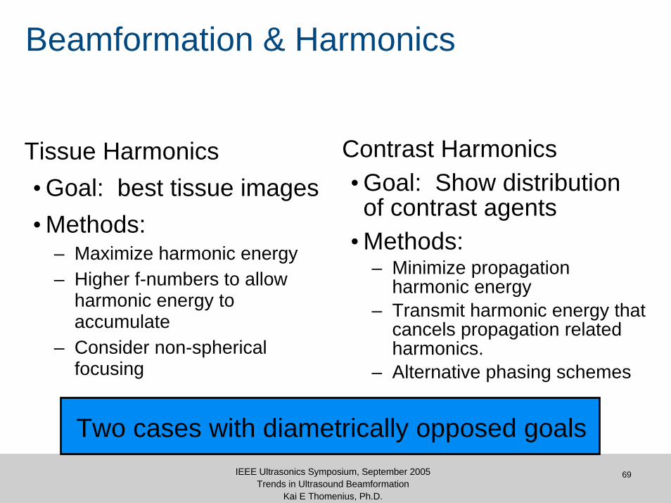
Beamformation & Harmonics
Tissue Harmonics• Goal: best tissue images• Methods:
– Maximize harmonic energy– Higher f-numbers to allow
harmonic energy to accumulate
– Consider non-spherical focusing
Contrast Harmonics• Goal: Show distribution of contrast agents
• Methods:– Minimize propagation
harmonic energy– Transmit harmonic energy that
cancels propagation related harmonics.
– Alternative phasing schemes
Two cases with diametrically opposed goals

Channel Count Issues
71IEEE Ultrasonics Symposium, September 2005Trends in Ultrasound Beamformation
Kai E Thomenius, Ph.D.
Whither Channel Count?
First 128 channel system introduced in 1983.• Huge majority of high-end systems are still at 128 channels.
Does it make sense to go higher?• What’s the cost/benefit trade-off?• Will the performance improve proportionately to the cost?
What are some of the reasons for increasing it?• Elevation focusing• Real-time 3D/4D• Aberration correction
72IEEE Ultrasonics Symposium, September 2005Trends in Ultrasound Beamformation
Kai E Thomenius, Ph.D.
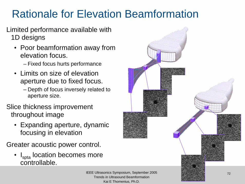
Rationale for Elevation BeamformationLimited performance available with
1D designs• Poor beamformation away from
elevation focus.– Fixed focus hurts performance
• Limits on size of elevation aperture due to fixed focus.
– Depth of focus inversely related to aperture size.
Slice thickness improvement throughout image• Expanding aperture, dynamic
focusing in elevation
Greater acoustic power control.• Ispta location becomes more
controllable.
73IEEE Ultrasonics Symposium, September 2005Trends in Ultrasound Beamformation
Kai E Thomenius, Ph.D.
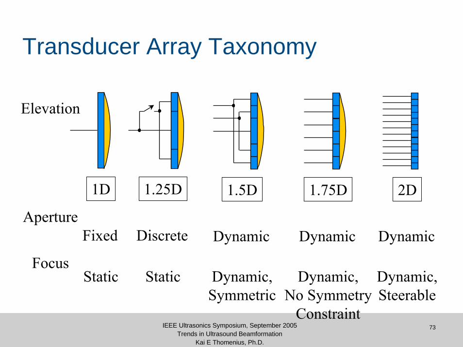
Transducer Array Taxonomy
1.75D
ApertureFixed
Focus
Discrete Dynamic
Static Dynamic,Symmetric
Dynamic,No Symmetry
Constraint
Dynamic,Steerable
Static
Dynamic Dynamic
1D 1.25D 1.5D 2D
Elevation

74IEEE Ultrasonics Symposium, September 2005Trends in Ultrasound Beamformation
Kai E Thomenius, Ph.D.
Phantom with 2 mm Spherical Cysts
Single- vs. Multi-Row Arrays
SingleRow
Multi-Row
75IEEE Ultrasonics Symposium, September 2005Trends in Ultrasound Beamformation
Kai E Thomenius, Ph.D.
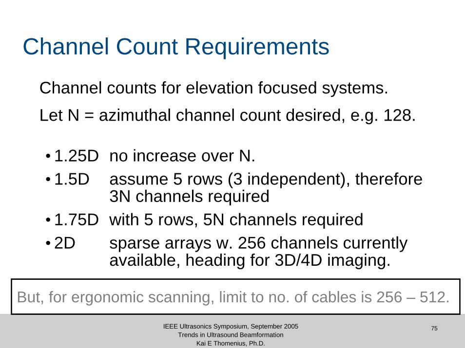
Channel Count Requirements
Channel counts for elevation focused systems. Let N = azimuthal channel count desired, e.g. 128.
• 1.25D no increase over N.• 1.5D assume 5 rows (3 independent), therefore
3N channels required• 1.75D with 5 rows, 5N channels required• 2D sparse arrays w. 256 channels currently
available, heading for 3D/4D imaging.
But, for ergonomic scanning, limit to no. of cables is 256 – 512.
3D/4D Challenges
77IEEE Ultrasonics Symposium, September 2005Trends in Ultrasound Beamformation
Kai E Thomenius, Ph.D.
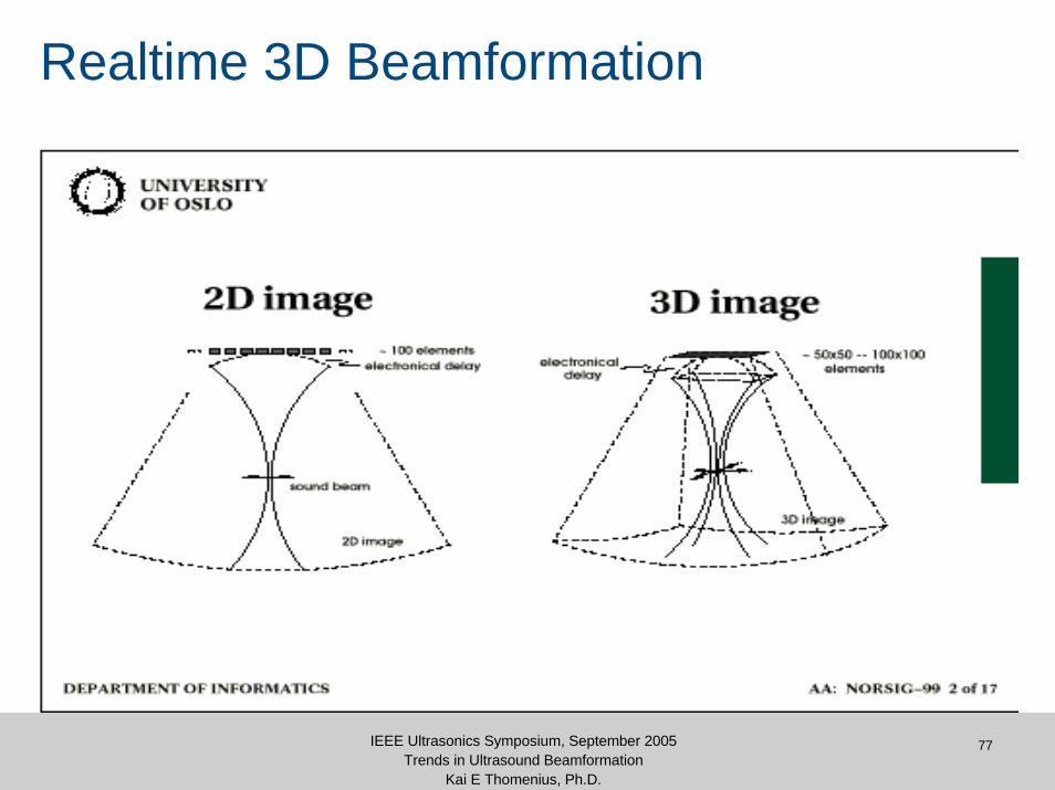
Realtime 3D Beamformation
78IEEE Ultrasonics Symposium, September 2005Trends in Ultrasound Beamformation
Kai E Thomenius, Ph.D.
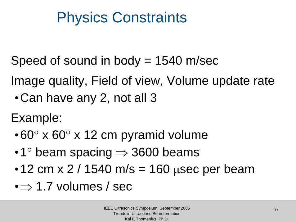
Physics Constraints
Speed of sound in body = 1540 m/secImage quality, Field of view, Volume update rate•Can have any 2, not all 3
Example:•60° x 60° x 12 cm pyramid volume•1° beam spacing ⇒ 3600 beams•12 cm x 2 / 1540 m/s = 160 μsec per beam•⇒ 1.7 volumes / sec
79IEEE Ultrasonics Symposium, September 2005Trends in Ultrasound Beamformation
Kai E Thomenius, Ph.D.
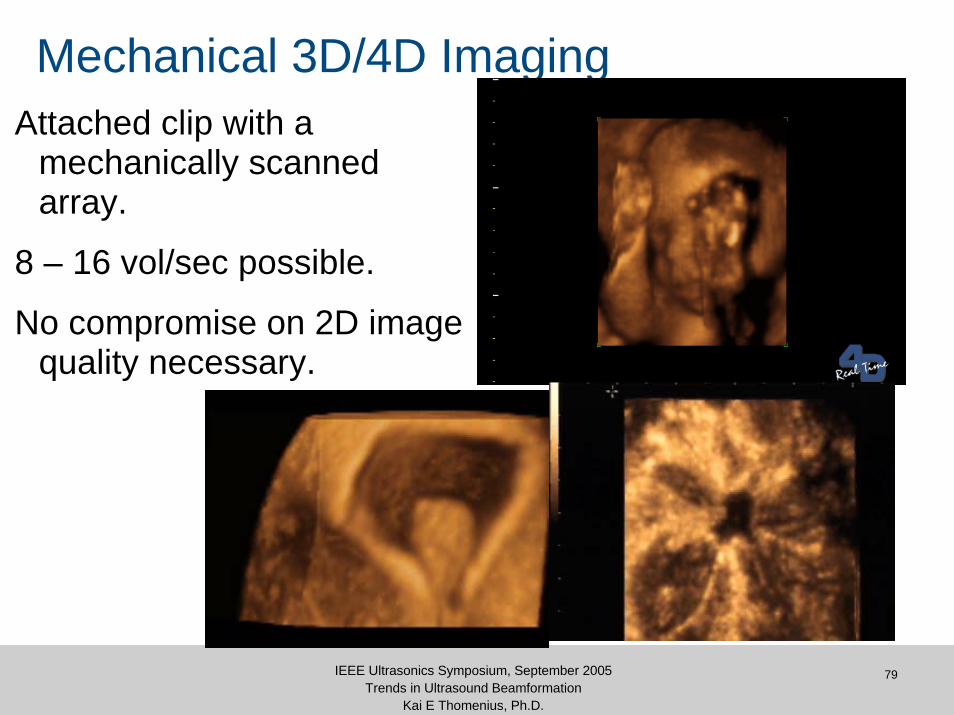
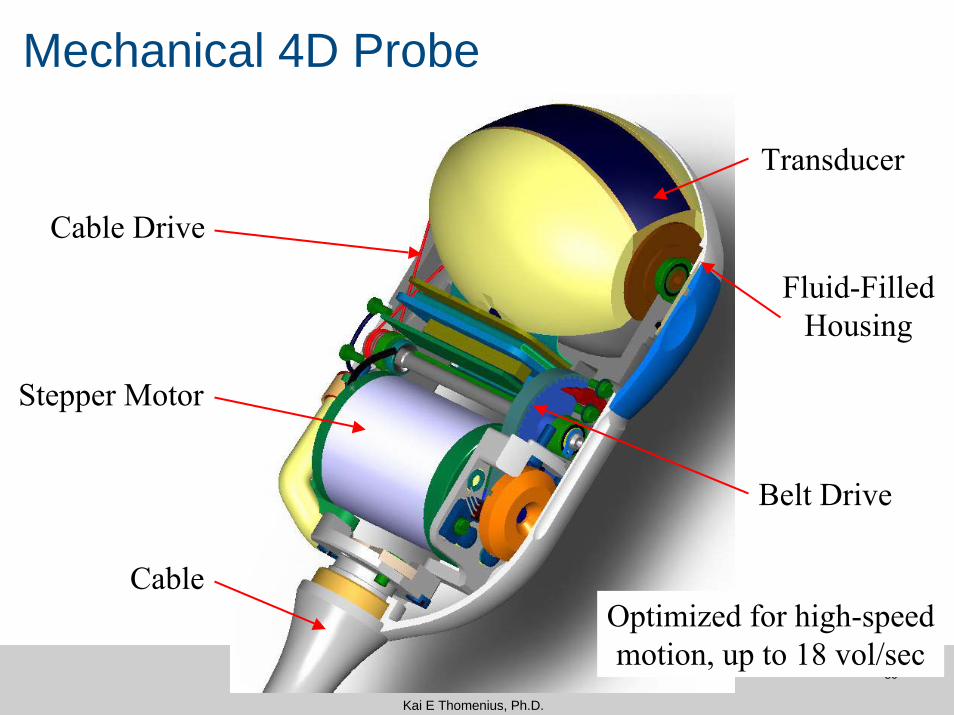
Mechanical 3D/4D ImagingAttached clip with a
mechanically scanned array.
8 – 16 vol/sec possible.
No compromise on 2D image quality necessary.
80IEEE Ultrasonics Symposium, September 2005Trends in Ultrasound Beamformation
Kai E Thomenius, Ph.D.
Mechanical 4D Probe
Cable Drive
Belt Drive
Transducer
Stepper Motor
CableOptimized for high-speedmotion, up to 18 vol/sec
Fluid-FilledHousing

81IEEE Ultrasonics Symposium, September 2005Trends in Ultrasound Beamformation
Kai E Thomenius, Ph.D.
Multi-line Acquisition
Transmit beam is broader than receive beam• transmit is static focus, usually
high f-number for max depth of field
Create 2 – 16 simultaneous receive beams within the transmit beam
Substantial increase in volume rate!
Essential for effective 4D imaging
82IEEE Ultrasonics Symposium, September 2005Trends in Ultrasound Beamformation
Kai E Thomenius, Ph.D.
Electronic 4D with 2D Arrays
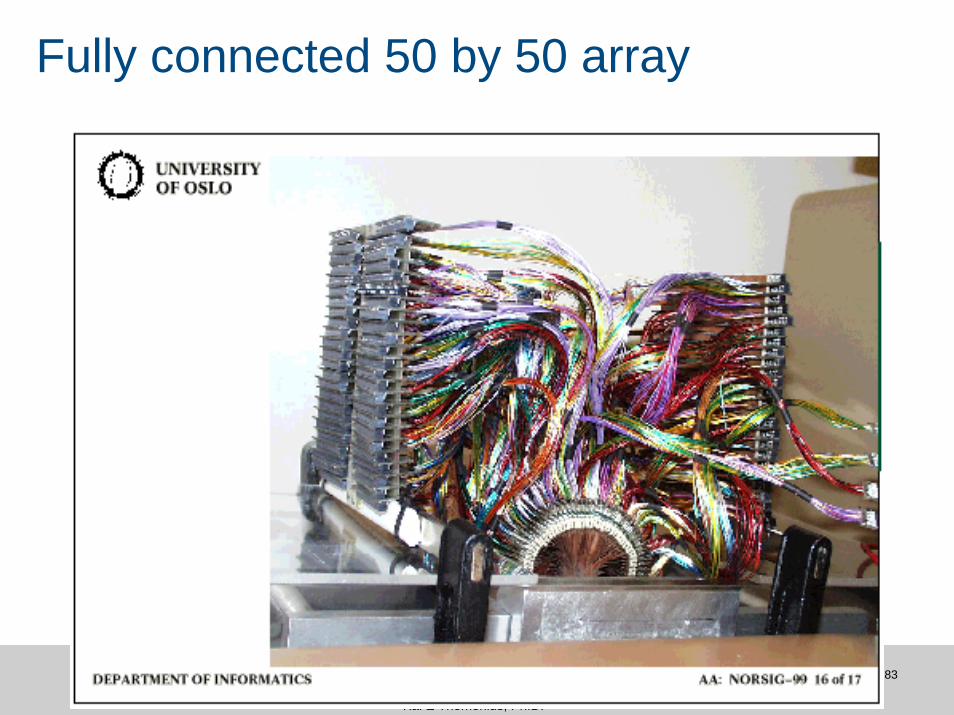
2D array can fire beams in any direction, in any sequenceSymmetric beamforming & image qualityMulti-line imaging for faster volume ratesThousands of transducer elements needed.• Cabling constraints severely limit options.
Novel solutions needed.
83IEEE Ultrasonics Symposium, September 2005Trends in Ultrasound Beamformation
Kai E Thomenius, Ph.D.
Fully connected 50 by 50 array
84IEEE Ultrasonics Symposium, September 2005Trends in Ultrasound Beamformation
Kai E Thomenius, Ph.D.
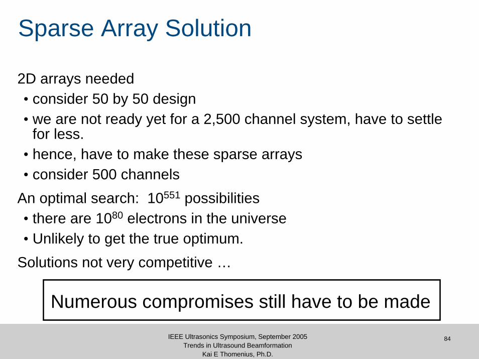
Sparse Array Solution
2D arrays needed• consider 50 by 50 design• we are not ready yet for a 2,500 channel system, have to settle
for less.• hence, have to make these sparse arrays• consider 500 channels
An optimal search: 10551 possibilities• there are 1080 electrons in the universe• Unlikely to get the true optimum.
Solutions not very competitive …
Numerous compromises still have to be made
85IEEE Ultrasonics Symposium, September 2005Trends in Ultrasound Beamformation
Kai E Thomenius, Ph.D.
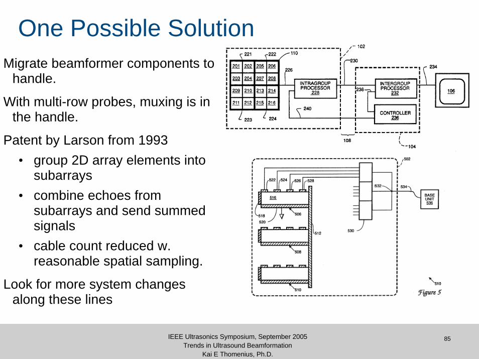
One Possible SolutionMigrate beamformer components to
handle.
With multi-row probes, muxing is in the handle.
Patent by Larson from 1993• group 2D array elements into
subarrays• combine echoes from
subarrays and send summed signals
• cable count reduced w. reasonable spatial sampling.
Look for more system changes along these lines
ProbeHandle
86IEEE Ultrasonics Symposium, September 2005Trends in Ultrasound Beamformation
Kai E Thomenius, Ph.D.
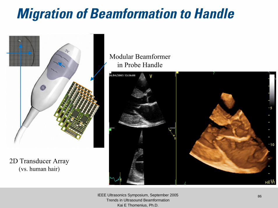
Migration of Beamformation to Handle
2D Transducer Array(vs. human hair)
Modular Beamformerin Probe Handle
87IEEE Ultrasonics Symposium, September 2005Trends in Ultrasound Beamformation
Kai E Thomenius, Ph.D.
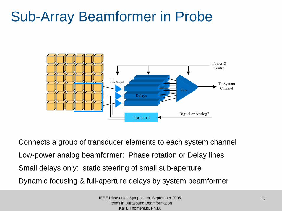
Sub-Array Beamformer in Probe
Preamps
SumDelays
To SystemChannel
Digital or Analog?
Power &Control
Transmit
Connects a group of transducer elements to each system channel
Low-power analog beamformer: Phase rotation or Delay lines
Small delays only: static steering of small sub-aperture
Dynamic focusing & full-aperture delays by system beamformer
88IEEE Ultrasonics Symposium, September 2005Trends in Ultrasound Beamformation
Kai E Thomenius, Ph.D.
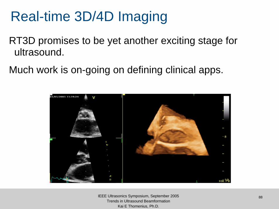
Real-time 3D/4D ImagingRT3D promises to be yet another exciting stage for ultrasound.
Much work is on-going on defining clinical apps.

Miniaturization

90
Miniaturization in Ultrasound: Trends
Typical scanner design• Most functions processing rather than data
acquisition oriented.• Such functions can be performed by
programmable devices such as ASICs, PCs.• Only purely ultrasound devices are transducers,
pulsers, and TGC amps.
Acquisition HW for ultrasound is very small compared to other modalities, hence size reduction possibilities are excellent.

91
Migration of HW Functionality to SW
• Conversion of HW functionality to software since ’95:• PC-based back end
• Scan conversion• Doppler processing• Image processing including 3D/4D rendering
• Can more functions migrate to SW?• Beamformation migration more challenging• Two start-ups have offered products w. SW
beamformation
92
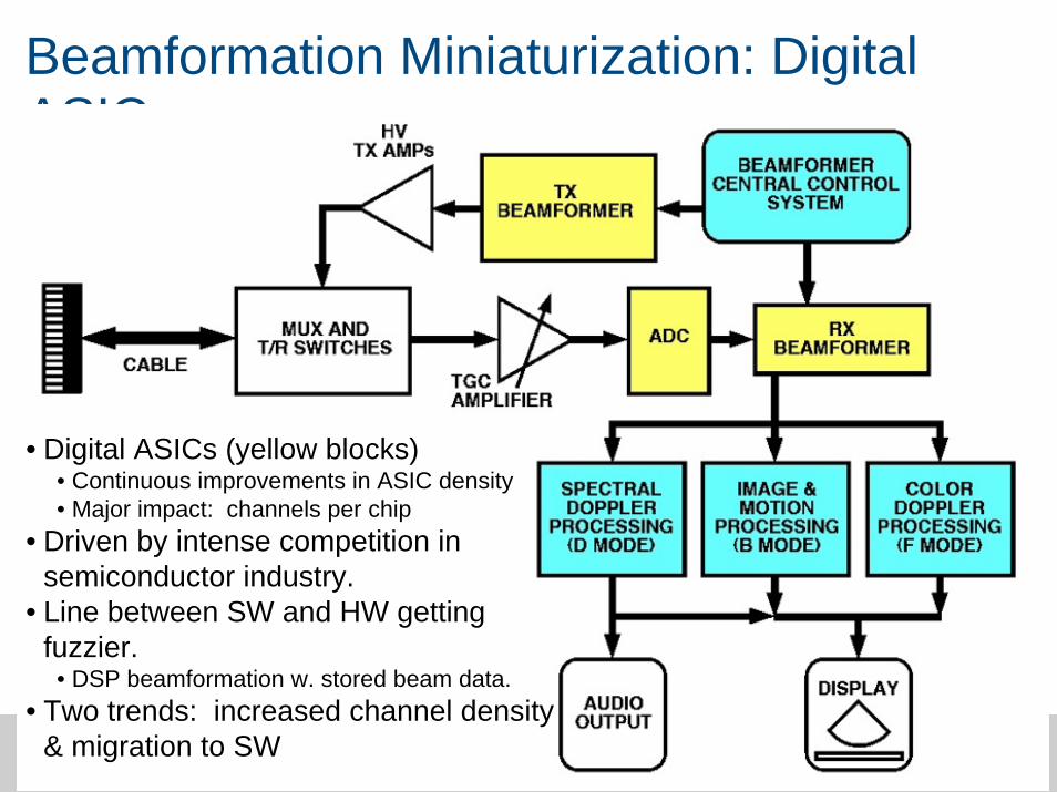
Beamformation Miniaturization: Digital ASICs
• Digital ASICs (yellow blocks)• Continuous improvements in ASIC density • Major impact: channels per chip
• Driven by intense competition in semiconductor industry.
• Line between SW and HW getting fuzzier.
• DSP beamformation w. stored beam data.• Two trends: increased channel density
& migration to SW
93
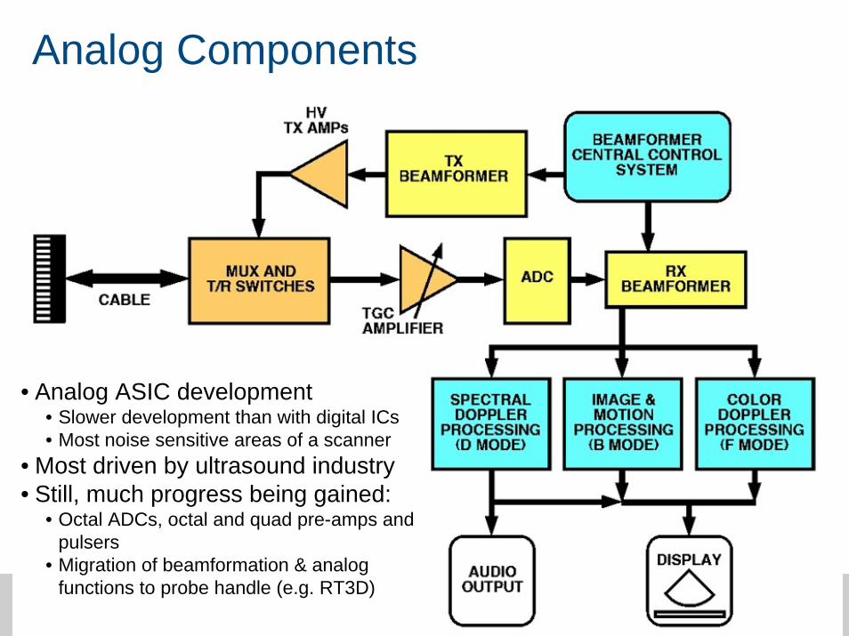
Analog Components
• Analog ASIC development• Slower development than with digital ICs• Most noise sensitive areas of a scanner
• Most driven by ultrasound industry• Still, much progress being gained:
• Octal ADCs, octal and quad pre-amps and pulsers
• Migration of beamformation & analog functions to probe handle (e.g. RT3D)
94IEEE Ultrasonics Symposium, September 2005Trends in Ultrasound Beamformation
Kai E Thomenius, Ph.D.
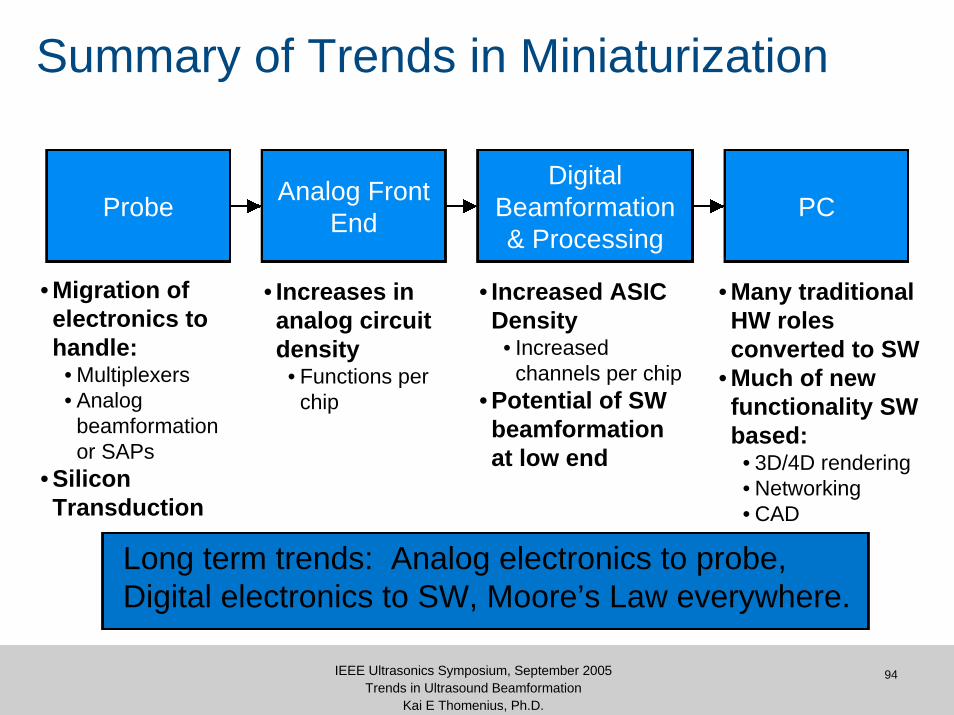
Summary of Trends in Miniaturization
Probe Analog Front End
Digital Beamformation & Processing
PC
• Migration of electronics to handle:
• Multiplexers• Analog
beamformation or SAPs
• Silicon Transduction
• Increases in analog circuit density
• Functions per chip
• Increased ASIC Density
• Increased channels per chip
• Potential of SW beamformation at low end
• Many traditional HW roles converted to SW
• Much of new functionality SW based:
• 3D/4D rendering• Networking• CAD
Long term trends: Analog electronics to probe, Digital electronics to SW, Moore’s Law everywhere.
95IEEE Ultrasonics Symposium, September 2005Trends in Ultrasound Beamformation
Kai E Thomenius, Ph.D.
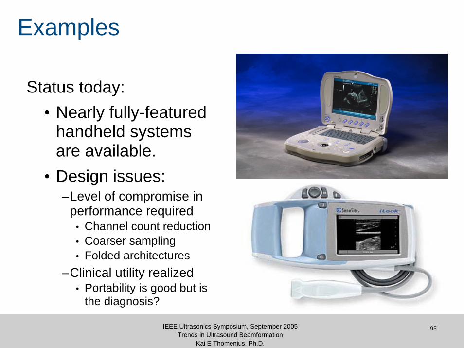
Examples
Status today:• Nearly fully-featured
handheld systems are available.
• Design issues:–Level of compromise in
performance required• Channel count reduction• Coarser sampling• Folded architectures
–Clinical utility realized • Portability is good but is
the diagnosis?

Aberration Correction

97IEEE Ultrasonics Symposium, September 2005Trends in Ultrasound Beamformation
Kai E Thomenius, Ph.D.
State-of-the-Art in Ultrasound Imaging
Focusing = Geometry, or…
People are just bags of waterIt’s a Crude
Approximation

98IEEE Ultrasonics Symposium, September 2005Trends in Ultrasound Beamformation
Kai E Thomenius, Ph.D.
Real-World Imaging
Fat and Muscle Layers Degrade the Image
Digital Beamformer Accuracy is Wasted
Time-delay Errors from the Abdominal Wall are
10-50 Times Larger than beamformer delay
quanta.
99IEEE Ultrasonics Symposium, September 2005Trends in Ultrasound Beamformation
Kai E Thomenius, Ph.D.
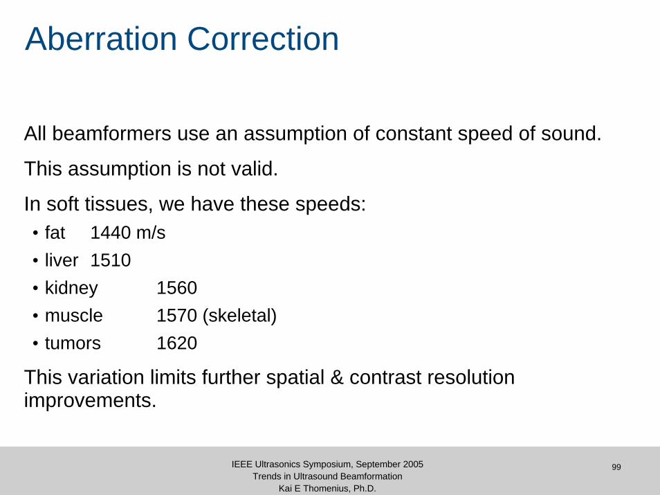
Aberration Correction
All beamformers use an assumption of constant speed of sound.
This assumption is not valid.
In soft tissues, we have these speeds:• fat 1440 m/s• liver 1510• kidney 1560• muscle 1570 (skeletal)• tumors 1620
This variation limits further spatial & contrast resolution improvements.

100IEEE Ultrasonics Symposium, September 2005Trends in Ultrasound Beamformation
Kai E Thomenius, Ph.D.
Beamforming With Aberration
τττττττ
Aberrating Layer,
Channel data poorly aligned
Point-like scatterer
Spherical wavefronts
TransducerGeometric beamforming delays
0cc ≠
101IEEE Ultrasonics Symposium, September 2005Trends in Ultrasound Beamformation
Kai E Thomenius, Ph.D.
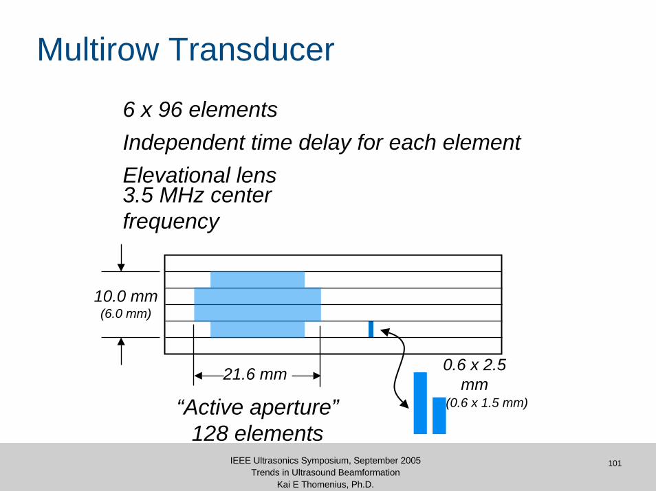
Multirow Transducer
6 x 96 elements
3.5 MHz center frequency
Elevational lens
“Active aperture”128 elements
0.6 x 2.5 mm
(0.6 x 1.5 mm)
10.0 mm(6.0 mm)
21.6 mm
Independent time delay for each element
102IEEE Ultrasonics Symposium, September 2005Trends in Ultrasound Beamformation
Kai E Thomenius, Ph.D.
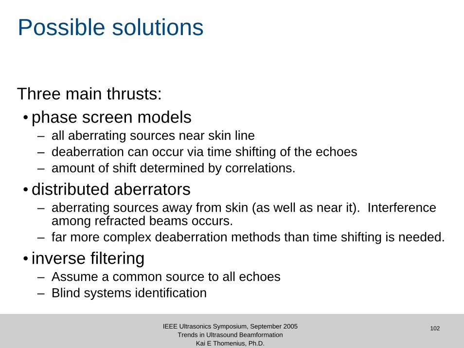
Possible solutions
Three main thrusts:• phase screen models
– all aberrating sources near skin line– deaberration can occur via time shifting of the echoes– amount of shift determined by correlations.
• distributed aberrators– aberrating sources away from skin (as well as near it). Interference
among refracted beams occurs.– far more complex deaberration methods than time shifting is needed.
• inverse filtering– Assume a common source to all echoes– Blind systems identification
103IEEE Ultrasonics Symposium, September 2005Trends in Ultrasound Beamformation
Kai E Thomenius, Ph.D.
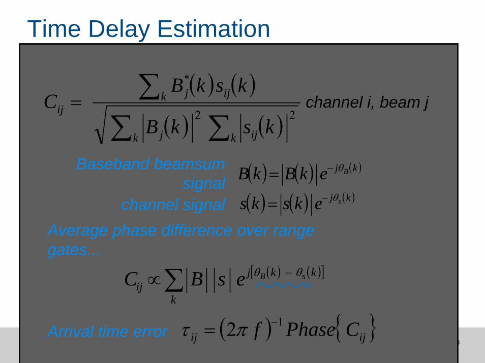
Time Delay Estimation
Baseband beamsum signal
channel signal
( ) ( ) ( )kj BekBkB θ−=
( ) ( ) ( )kj seksks θ−=Average phase difference over range gates...
channel i, beam j ( ) ( )
( ) ( )∑ ∑∑=
k k ijj
k ijjij
kskB
kskBC
22
*
Arrival time error ( ) { }ijij CPhasef 12 −= πτ
( ) ( )[ ]kkj
kij
sBesBC θθ −∑∝

104IEEE Ultrasonics Symposium, September 2005Trends in Ultrasound Beamformation
Kai E Thomenius, Ph.D.
Time Delay Estimation
Arrival time error ( ) { }ii CPhasef 12 −= πτ
For thin aberrating layer, time delay for a given element is independent of
beam
Average Cij over all beams jto which element i contributes
beam j
element i
105IEEE Ultrasonics Symposium, September 2005Trends in Ultrasound Beamformation
Kai E Thomenius, Ph.D.
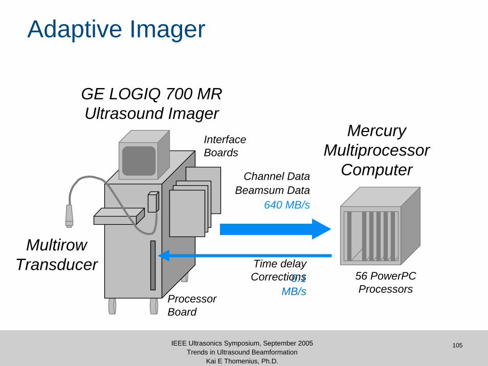
Adaptive Imager
GE LOGIQ 700 MRUltrasound Imager
MultirowTransducer
InterfaceBoards
ProcessorBoard
Time delay Corrections0.1
MB/s
Beamsum DataChannel Data
640 MB/s
MercuryMultiprocessor
Computer
56 PowerPC Processors
106IEEE Ultrasonics Symposium, September 2005Trends in Ultrasound Beamformation
Kai E Thomenius, Ph.D.
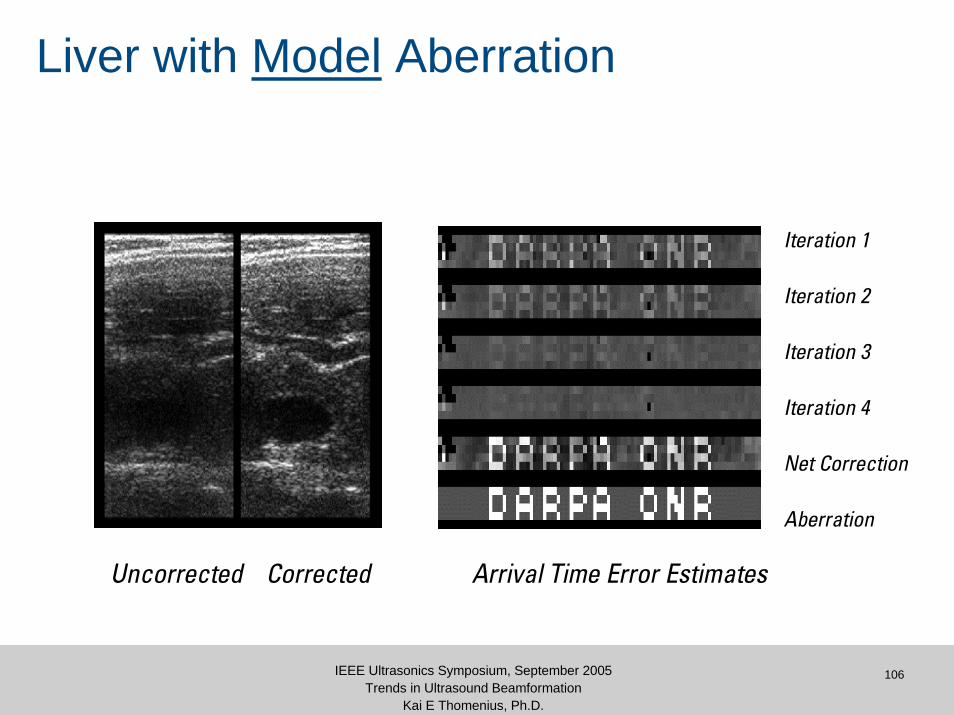
Uncorrected Corrected
Iteration 1
Iteration 2
Iteration 3
Iteration 4
Net Correction
Aberration
Arrival Time Error Estimates
Liver with Model Aberration
107IEEE Ultrasonics Symposium, September 2005Trends in Ultrasound Beamformation
Kai E Thomenius, Ph.D.
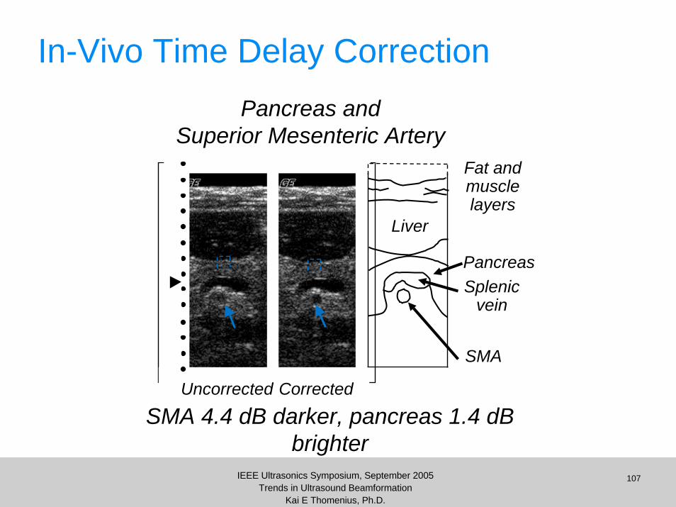
In-Vivo Time Delay Correction
Uncorrected Corrected
SMA 4.4 dB darker, pancreas 1.4 dB brighter
Pancreas
Fat andmusclelayers
Splenicvein
SMA
Liver
Pancreas andSuperior Mesenteric Artery
108IEEE Ultrasonics Symposium, September 2005Trends in Ultrasound Beamformation
Kai E Thomenius, Ph.D.
Aberration Correction
Perhaps the major beamformer related challenge today.
Several groups throughout the world are addressing this issue.
Stay tuned.
109IEEE Ultrasonics Symposium, September 2005Trends in Ultrasound Beamformation
Kai E Thomenius, Ph.D.
Summary: New areas of interest
Hand held systems• how small can we make a beamformer?
How can we increase channel count w/o major cost increase?• Will clinical benefits justify increased costs?• Search for new methods of beamformation, e.g.
– Delta-sigma beamformation
Realtime 3D/4D• Migration of beamformer functions to probe handle
Methods of combating slow speed of sound• Multi-line strategies
110IEEE Ultrasonics Symposium, September 2005Trends in Ultrasound Beamformation
Kai E Thomenius, Ph.D.
Conclusions
Major trends in beamformers:• increased channel count is highly likely
– real-time 3D– elevation beamforming– sparse arrays
• to accomplish this, several approaches may be possible:– migration of beamformer functions to probe handle– increased channel density per board– synthetic aperture schemes– novel beamformation approaches
• new applications, directions– taking advantage of nonlinear propagation effects– contrast agents

111IEEE Ultrasonics Symposium, September 2005Trends in Ultrasound Beamformation
Kai E Thomenius, Ph.D.
BibliographyF. Anderson, ``3D ellipsoidal backprojection images from large arrays'', 1992 IEEE Ultrasonics Symposium Proc., pp. 1223-1226, (1992).W.A. Anderson, et al., ``A new real time phased array Sector Scanner for imaging the entire adult human heart'', {Ultrasound in Medicine}, 3B Edition, pp. 1547-1558, (1977).Austeng and S. Holm, " Sparse Arrays for Real-time 3D Imaging, Simulated and Experimental Results," in Proc. IEEE Ultrasonics Symp.2000, San Juan, Puerto Rico, Oct 2000K.N. Bates, ``Tolerance analysis for phased arrays'', {Acoustic Imaging}, Vol. 9, edited by K. Wang, pp. 239-262, Plenum Press, New York, (1980).W.L. Beaver, ``Phase error effects in phased array beam steering'', 1977 IEEE Ultrasonics Symposium Proc., pp. 264-267, (1977).N. Bom, C.T. Lancee, and J. Honkoop, ``Ultrasonics viewer for cross-sectional analysis of moving cardiac structures'', Bio-med Engng 6:500, (1971).C.B. Burckhardt, P.-A. Grandchamp, and H. Hoffman, ``An experimental 2 MHz synthetic aperture sonar system intended for medical use'', IEEE Trans. Son. Ultrason. vol. 21, pp. 1-6, (1974).C.B. Burckhardt, P.-A. Grandchamp, H. Hoffman, and R. Fehr, ``A simplified ultrasound phased arrays sector scanner'', {Echocardiology}, ed. C.T. Lancee, pp. 385-393, (1979).C.R. Cooley and B.S. Robinson, ``Synthetic focus imaging using partial datasets'', 1994 IEEE Ultrasonics Symposium Proc., vol.94CH3468-6, pp. 1539-1542, (1994).Daft, CMW, Leue, WM, Thomenius, KE, Macdonald, MC, Odegaard, LA, "Comprehensive Imager Simulation for Improved Acoustic Power Control," 1999 IEEE Ultrasonics Symposium, pp. 1571 – 1757, 1999.C.M.W. Daft, D.G. Wildes, L.J. Thomas, L.S. Smith, R.S. Lewandowski, W.M.Leue, K.W. Rigby, C.L. Chalek, and W.T. Hatfield, ''A 1.5D transducer for medical ultrasound'', 1994 IEEE Ultrasonics Symposium Proceedings, pp.~1491-1495.R. E. Davidsen, J. A. Jensen and S. W. Smith, ``Two dimensional random arrays for real time volumetric imaging,'' Ultrason. Imag., vol 16, pp 143-a63, 1994.M.D. Eaton, R.D. Melen, and J.D. Meindl, ``A flexible, real-time system for experimentation in phased-array ultrasound imaging'', {Acoustic Imaging}, Vol. 8, edited by A.F. Metherell, pp. 55-67, Plenum Press, New York,(1980)
S. Freeman, P.-C. Li, and M. O'Donnell, ``Retrospective dynamic transmit focusing'', Ultrasonic Imaging, vol. 17, pp. 173-196, (1995).S.M. Gehlbach and R.E. Alvarez, ``Digital ultrasound imaging techniques usingvector sampling and raster line reconstruction'', Ultrasonic Imaging, vol. 3, pp. 83-107, (1981).R.T. Hoctor and S.A. Kassam, ``The unifying role of the coarray in aperture synthesis for coherent and incoherent imaging'', IEEE Proc., vol. 78, pp. 735-752, (1990).S. Holm, "Sparse and irregular sampling in array processing," Proc. IEEE Int. Conf. Acoust., Speech, Sign. Proc. 2000, Istanbul, Turkey, June 2000K. Jeon, M.H. Bae, S.B. Park, and S.D. Kim, ``An efficient real time focusing delay calculation in ultrasonic imaging systems'', Ultrasonic Imaging, vol. 16, pp. 231-248, (1994).M. Karaman, A. Atalar, and H. Koymen, ``VLSI circuits for adaptive digital beamforming in ultrasound imaging'', IEEE Trans. Med. Imaging, vol. 12, pp. 711-720, (1993).M. Karaman, P.-C. Li, and M. O'Donnell, ``Synthetic Aperture Imaging for Small Scale Systems'', IEEE Transactions of Ultrasonics, Ferroelectrics, and Frequency Control UFFC-42, 429-442 (1995)H.E. Karrer, J.F. Dias, J.D. Larson, R.D. Pering, ``A phased array acoustic imaging system for medical use'', 1980 Ultrasonics Symposium Proceedings, pp.757-762, IEEE 80CH1602-2, (1980).J.H. Kim, T.K. Song, and S.B. Park, ``A pipelined sampled delay focusing in ultrasound imaging systems'', Ultrasonic Imaging, vol. 9, pp. 75-91, (1987).D.L. King, ``Real-time cross-sectional ultrasonic imaging of the heart using a linear array multi-element transducer'', J. Clin. Ultrasound, vol. 2, p. 222, (1974).W.C. Knight, R.G. Pridham, and S.M. Kay, ``Digital Signal Processing for Sonar'', Proc. IEEE, vol. 69, pp. 1451-1507, (1981).J.D. Larson, III, “2-D Phased array ultrasound imaging system with distributed phasing”, US Patent, no. 5,229,933, Jul. 20, 1993.P.-C. Li and M. O'Donnell, ``Synthetic aperture imaging using a Lagrange based filtering technique'', Ultrasonic Imaging, vol. 14, pp. 354-366, (1992).G. R. Lockwood, P. C. Li, M. O'Donnell, and F. S. Foster, ``Optimizing the radiation pattern of sparse periodic linear arrays'', IEEE Transactions of Ultrasonics, Ferroelectrics, and Frequency Control UFFC-43, pp.7-14 (1996).G.
112IEEE Ultrasonics Symposium, September 2005Trends in Ultrasound Beamformation
Kai E Thomenius, Ph.D.
BibliographyR. Lockwood and F. S. Foster, ``Optimizing the radiation pattern of sparse periodic two dimensional arrays'', IEEE Transactions of Ultrasonics, Ferroelectrics, and Frequency Control UFFC-43, pp. 15-19 (1996).G.R. Lockwood and F.S. Foster, ``Design of sparse array imaging systems'', 1995 IEEE Ultrasonics Symposium Proceedings, vol. 95CH35844, pp. 1237-1243,(1995). J.-Y. Lu and J.F. Greenleaf, ``Nondiffracting X waves-exact solutions to free-0space scalar wave equation and their finite aperture realizations'',IEEE Transactions of Ultrasonics, Ferroelectrics, and Frequency Control UFFC-39, pp. 19-31 (1992).R.M. Lutoff, A. Vieli, and S. Basler, ``Ultrasonic phased array scanner with digital echo synthesis for Doppler echocardiography'', IEEE Transactions of Ultrasonics, Ferroelectrics, and Frequency Control, vol. UFFC-36, pp. 494-506, (1989).P.A. Magnin, O.T. von Ramm, and F. Thurstone, ``Delay quantization error in phased array images'', IEEE Trans. Sonics Ultrasonics, vol. SU-28, pp. 305-310, (1981)G.F. Manes, C. Atzeni, and C. Susini, ``Design of a simplified delay system for ultrasound phased array imaging'', IEEE Transactions of Sonics Ultrasonics, vol. SU-30, pp. 350-354, (1983).R.E. McKeighen and M.P. Buchin, ``New techniques for dynamically variable electronic delays for real time ultrasonic imaging'', 1977 Ultrasonics Symposium Proceedings, pp. 250-254, IEEE 77CH1264-1, (1977).R.A. Mucci, ``A comparison of efficient beamforming algorithms'', IEEE Trans.Acoust. Speech, Signal Proc., vol. 32, pp. 548-558,(1984).R.A. Mucci and R.G. Pridham, ``Impact of beam steering errors on shifted sideband and phase shift beamforming techniques'', JASA vol. 69, pp. 1360-1368, (1981).K. Nagai, ``A new synthetic-aperture focusing method for ultrasonic B-scan imaging by the Fourier transform'', IEEE Transactions Son.Ultrason. vol. 32, pp. 531-536, (1985).M. Nikoonahad, ``Synthetic focused image reconstruction in the presence of a finite delay noise'', 1986 IEEE Ultrasonics Symposium, IEEE 86CH2375-4, pp. 819-824, (1990).L.F. Nock and G.E. Trahey, ``Synthetic receive aperture imaging with phase correction for motion and for tissue inhomogeneities - Part I: Basic Principles'', IEEE Trans. Ultrason., Ferroelectr.,Freq. Control, vol. 39, pp. 489-495, (1992).
M. O'Donnell, ``Applications of VLSI circuits to medical imaging'', Proc. IEEE, vol. 76, pp. 1106-1114, (1988).M. O'Donnell et al., ``Real-time phased-array imaging using digital beamforming and autonomous channel control'', 1990 IEEE Ultrasonics Symposium, pp. 1499-1502, (1990).M. O'Donnell and L.J. Thomas, ``Efficient synthetic aperture imaging from a circular aperture with possible application to catheter-based imaging'', IEEE Transactions of Ultrasonics, Ferroelectrics, and Frequency Control UFFC-39, pp. 366-380, (1992).M. O'Donnell, B. M. Shapo, M. J. Eberle and D. Stephens, ``Experimental studies on an efficient catheter array imaging system'', Ultrasonic Imaging 17, pp. 83-94, (1995).D.K. Peterson and G.S. Kino, ``Real-time digital image reconstruction: A description of imaging hardware and an analysis of quantization errors'', IEEE Trans. Sonics Ultrason., vol. SU-31, pp. 337-351,(1984).Reid, J.M, and Wild, J.J., ``Current developments in ultrasonic equipment for mechanical diagnosis'', in {Proc. Nat. Electronics Council}, vol. 12, pp. 44-58, 1956.K. W. Rigby, C. L. Chalek, B. H. Haider, M. O'Donnell, R. S. Lewandowski, M. O'Donnell, L. S. Smith and D. G. Wildes, "Improved In Vivo Abdominal Image Quality Using Real-time Estimation and Correction of Wavefront Arrival Time Errors," 2000 IEEE Ultrasonics Symposium.K. W. Rigby, "Real-time Correction of Beamforming Time Delay Errors in Abdominal Ultrasound Imaging," SPIE Medical Imaging 2000, February 12-18, 2000, San Diego, CAB.J. Savord, “Beamforming methods and apparatus for three-dimensional ultrasound imaging using two-dimensional transducer array”, US Patent, no. 6,013,032, Jan. 11, 2000.T.A. Shoup and J. Hart, ``Ultrasonic imaging systems'', 1988 IEEE Ultrasonics Symposium, pp. 863-871, (1988).S. W. Smith, G. E. Trahey, and O. T. von Ramm, ``Two dimensional arrays for medical ultrasound'', Ultrasonic Imaging 14, 213-233 (1992).J.C. Somer, ``Electronic sector scanning for ultrasonic diagnosis'', Ultrasonics 6:153 - 159, (1968).

113IEEE Ultrasonics Symposium, September 2005Trends in Ultrasound Beamformation
Kai E Thomenius, Ph.D.
BibliographyT.K. Song, and S.B. Park, ``A new digital phased array system for dynamic focusing and steering with reduced sampling rate'', Ultrasonic Imaging, vol. 12, pp. 1-16, (1990).B.D. Steinberg, Principles of Aperture and Array System Design, J. Wiley and Sons, New York, NY, (1976)B.D. Steinberg, ``Digital beamforming in ultrasound'', IEEE Transactions of Ultrasonics, Ferroelectrics, and Frequency Control UFFC-39, pp. 716-721, (1992).R.H. Tancrell, J. Callerame, and D.T. Wilson, ``Near-field, transient acoustic beamforming with arrays'', 1978 Ultrasonics Symposium Proceedings, pp.339-343, IEEE 78CH1344-ISU, (1978).K.E. Thomenius, “New Directions for beamformation in medical ultrasound,” Proc. SPIE, vol. 3664, San Diego, CA, 1999.F.L. Thurstone and O.T. von Ramm, ``Electronic beam steering for ultrasonic imaging'' in {Ultrasound in Medicine}, ed. M. deVlieger et al. pp. 43 - 48, American Elsevier Publishing Co., New York (1974).P. Tournois, S. Calisti, Y. Doisy, J.M. Bureau, F. Bernard, ''A 128*4 channels 1.5D curved Linear array for medical imaging'', Proc. of 1995 IEEE Ultrasonics Symposium, pp.~1331-1335.O.T. von Ramm and F.L. Thurstone, ``Thaumascan: Improved image quality and clinical usefulness'', in {Ultrasound in Medicine}, vol. 2, p. 463, Plenum Press, NY, NY, (1970)J.T. Walker and J.D. Meindl, ``A digitally controlled CCD dynamically focused phased array'', 1975 Ultrasonics Symposium, pp. 80-83, (1975).P. K. Weber, R. M. Schmitt, B. D. Tylkowski, J. Steck, ``Optimization of random sparse 2-D transducer arrays for 3-D electronic beam steering and focusing,'' in Proc. 1994 IEEE Ultrason. Symp., pp 1503-1506.D. Wildes, et al., ``Elevation performance of 1.25D and 1.5D transducer arrays'', IEEE Trans. UFFC, vol. 44, pp. 1027 - 1037, 1997.J. Wright, ``Resolution issues in medical ultrasound'', 1985 IEEE Ultrasonics Symposium Proceedings, IEEE 85CH 2209-5, pp. 793-799 (1985).J.T. Ylitalo and H. Ermert, ``Ultrasound synthetic aperture imaging: monostaticapproach'', IEEE Trans. Ultrason., Ferroelectr.,Freq., Control, vol. 41, pp. 333-339, (1994)