Embed Size (px)
Citation preview
RECENT DEVELOPMENTS ON THE HIGH POWER ECH INSTALLATION
AT THE DIN-D TOKAMAK
by Jm LOHR, D. PONCE, RmW. CALLIS,
J.L. DOANE, H. IKEZI, and C.P. MOELLER
SEPTEMBER 1998
C€N€RAL ATOMICS

DISCLAIMER
Portions of this document may be illegible in electronic image products. Images are produced from the best available original document.
,
G A-A22963
RECENT DEVELOPMENTS ON THE HIGH POWER ECH INSTALLATION
AT THE DIII-D TOKAMAK
by J. LOHR, D. PONCE, R.W. CALLIS,
J.L. DOANE, H. IKEZI, and C.P. MOELLER
This is a preprint of an invited paper presented at the 23rd International Conference on Infrared and Millimeter Waves, September 7-1 1,1998, Wivenhoe Park, Colchester, U.K., and to be printed in the Proceedings.
Work supported by U.S. Department of Energy
under Contract DE-AC03-89ER51114
GENERAL ATOMICS PROJECT 3466 SEPTEMBER 1998
GENE-L ATOMICS
Lohr et al. RECENTDEvELopMwrsONTHEHIGHpowERECHINsTALLATON
ATTHE DIU-D TOKAMAK
RECENT DEVELOPMENTS ON THE HIGH POWER ECH INSTALLATION AT THE DIII-D TOKAMAK
John Lohr, Dan Ponce, R.W. Callis, J.L. Doane, H. Ikezi, and C.P. Moeller
General Atomics San Diego, CaliJornia, U.S.A.
Abstract
The 110 GHz gyrotron installation on the DIII-D tokamak has been upgraded to three tubes in the megawatt class with plans for further upgrades. The latest addition uses a diamond output window. The report describes the installation, plans, and experimental results to date.
Key Words: Gyrotron, tokamak, millimeter wave systems, millimeter wave measurements.
I. Introduction
The 110 GHz gyrotron installation on the DIII-D tokamak has been incorporated into the experimental program as a research tool while in parallel being further characterized and upgraded. Two gyrotrons are in regular operation and a third is being installed. The first gyrotron is a Gycom “Centaur” model [ 11, which has reliably generated more than 800 kW for two second pulse lengths. The second gyrotron is a CPI VGT- 801 1A [2], which has regularly generated 750 kW at one second pulse length and has been tested at up to 1.09 MW for 600 ms pulse length and 750 kW for 1.3 s pulse length. For both gyrotrons, the pulse length limit is imposed by the gyrotron output window. For the Gycom tube, edge cooled BN is used and, for the CPI tube, face cooled double disk sapphire is used with a chlorofluorocarbon as the cooling medium.
GENWAL ATOMICS REPORT GA-A22963 1

2
FECENI'DEVELOPMENTS ONTIEHIGHFOWJ2REC!HIN~AL,LATION AT THE DIII-D TOKAMAK Lohr et ai.
These gyrotrons, operating both modulated and cw, have been used for power deposition profile measurements, transport studies, measure- ments of electron cyclotron current drive, heating, H-mode studies and magnetohydrodynamic mode stabilization. Using two different launchers, one injecting with a toroidal component and the other perpendicular to the magnetic field, comparisons between heating plus current drive and heating only were made to enhance the accuracy of the measurement of the electron cyclotron current drive. Changing the poloidal angle of the final launcher mirror permits the rf beam to be steered anywhere in the tokamak upper half plane and this feature, coupled with changes in the tokamak toroidal magnetic field, has been used in studies of off-axis electron cyclo- tron current drive, which is an essential element of advanced tokamak operation leading to steady state reactor-relevant regimes of operation for modest sized tokamak devices.
The waveguide run from the gyrotrons to the tokamak is about 40 m long in 3 1.75 mm diameter circular corrugated aluminum waveguide carrying the HE1,I mode. The waveguides include power monitors, switches for delivering the beams to the tokamak or dummy loads and remotely controllable polarizers, which can generate any desired elliptical polarization from the linearly polarized gyrotron output beams. The lines transmit more than 75% of the generated power to the tokamak, with about 4% total loss in the six miter bends and 18% loss in the Matching Optics Unit. The present setup is presented in Fig. 1.
There are two separate launcher assemblies displaced toroidally from each other by 15" in the tokamak plan view. Each launcher assembly can be connected to two gyrotrons. One launcher injects perpendicularly to the tokamak magnetic field and therefore primarily heats the plasma without driving current. The other launcher injects 19" off-perpendicular and therefore both heats and drives current in the plasma. The two fully operational gyrotrons could be connected as required to either of the launchers.
A third gyrotron, manufactured by CPI [3], has been tested at CPI and is being installed at DIII-D. This gyrotron uses a diamond output window and directly generates a Gaussian beam. Its parameters are described briefly below.
GENERAL ATOMICS REPORT GA-A22963

Toto total transmission line
1 2 3 4
Fig. 1. The gyrotrons are connected to the tokamak by circular waveguide carrying the HE1,1 mode, Both tubes can be connected either to antennas for perpendicular injection or for oblique injection and the rf beams can be steered poloidally in the upper half plane of the tokamak. Each waveguide line includes a forward and reflected power monitor, waveguide switch, dummy load, blocking valves, and remotely controlled polarizers. The lines are evacuated and are about 40 m in length.
w
RECENTDEVELOPMENTS ONTHEHIGHPOWERECHINSTALLATION AT THE DIII-D TOKAMAK Lohr et al.
11. Experimental Results
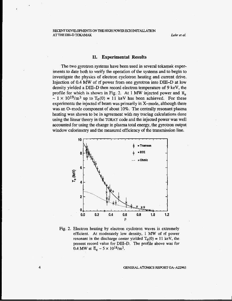
The two gyrotron systems have been used in several tokamak exper- iments to date both to verify the operation of the systems and to begin to investigate the physics of electron cyclotron heating and current drive. Injection of 0.4 MW of rf power from one gyrotron into DIII-D at low density yielded a DIE-D then record electron temperature of 9 keV, the profile for which is shown in Fig. 2. At 1 M W injected power and Ti, - 1 x 10¹⁹/m3 up to Te(0) = 11 keV has been achieved. For these experiments the injected rf beam was primarily in X-mode, although there was an 0-mode component of about 10%. The centrally resonant plasma heating was shown to be in agreement with ray tracing calculations done using the linear theory in the TORAY code and the injected power was well accounted for using the change in plasma total energy, the gyrotron output window calorimetry and the measured efficiency of the transmission line.
I * =~homson
+, =ECE
... =Ohmic
4
0.0 0.2 0.4 0.6 0.8 1 .o 1.2 P
Fig. 2. Electron heating by electron cyclotron waves is extremely efficient. At moderately low density, 1 M W of rf power resonant in the discharge center yielded Te(0) = 11 keV, the present record value for DIII-D. The profile above was for 0.4 MW at Ti, - 5 x 10¹⁸/m3.
GENERAL ATOMICS REPORT GA-A22963
Lohr et al. RECENTDEvELopMENTsONTHEHIGHKWERECHINsTALLATlON
ATTHEDIII-DTOKAMAK
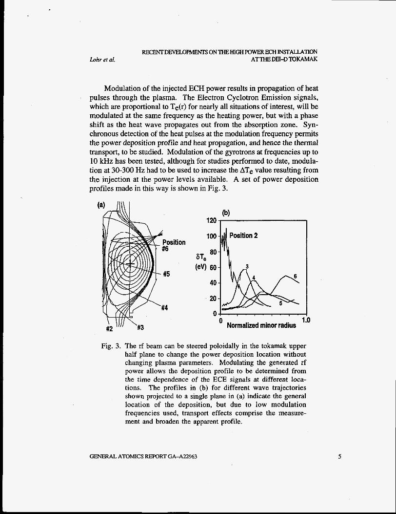
Modulation of the injected ECH power results in propagation of heat pulses through the plasma. The Electron Cyclotron Emission signals, which are proportional to Te(r) for nearly all situations of interest, will be modulated at the same frequency as the heating power, but with a phase shift as the heat wave propagates out from the absorption zone. Syn- chronous detection of the heat pulses at the modulation frequency permits the power deposition profile and heat propagation, and hence the thermal transport, to be studied. Modulation of the gyrotrons at frequencies up to 10 kHz has been tested, although for studies performed to date, modula- tion at 30-300 Hz had to be used to increase the ATe value resulting from the injection at the power levels available. A set of power deposition profiles made in this way is shown in Fig. 3.
100
80
60
40
20
0' Normalized minor radius
Fig. 3. The rf beam can be steered poloidally in the tokamak upper half plane to change the power deposition location without changing plasma parameters. Modulating the generated rf power allows the deposition profile to be determined from the time dependence of the ECE signals at different loca- tions. The profiles in (b) for different wave trajectories shown projected to a single plane in (a) indicate the general location of the deposition, but due to low modulation frequencies used, transport effects comprise the measure- ment and broaden the apparent profile.
GENERAL ATOMICS REPORT GA-A22963 5
RECENTDEYELOPh4ENISONTHEHIGHPOWERECHINSTALL,ATION AT THE DJII-D MKAh4AK Lohr et al.
Direct free space measurements of the beam profile in the tokamak showed that the launchers produce a circular Gaussian beam spot with a half maximum full width of about 12 cm. At low modulation frequencies the power deposition profile measurement is affected by transport, in- creasing the apparent breadth of the profile. The known 0-mode com- ponent of the injected rf beam also broadened the deposition profile due to low single pass absorption and subsequent randomization of polarization and trajectory on reflection, therefore the profiles measured using modul- ation and presented here are in general broader than the best achievable. Higher modulation frequencies will be possible with higher injected power levels and improved control of the polarization, recently implemented, will narrow the deposition profile inferred from the modulation measurements.
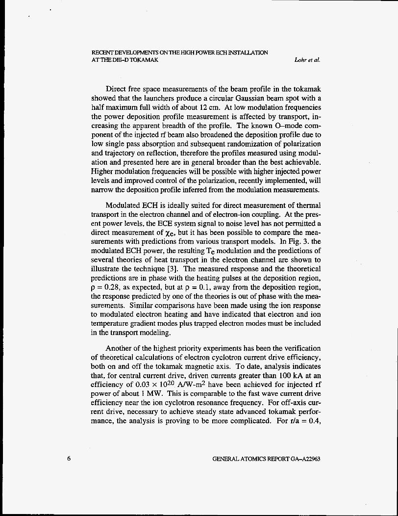
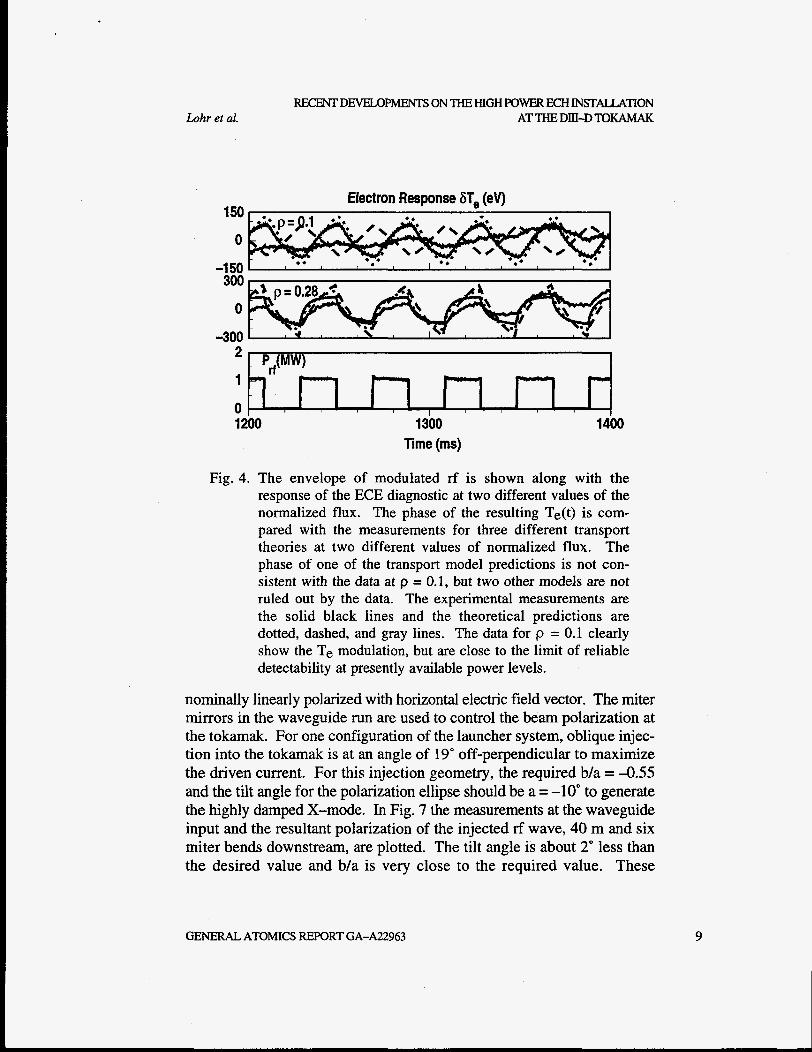
Modulated ECH is ideally suited for direct measurement of thermal transport in the electron channel and of electron-ion coupling. At the pres- ent power levels, the ECE system signal to noise level has not permitted a direct measurement of Xe, but it has been possible to compare the mea- surements with predictions from various transport models. In Fig. 3. the modulated ECH power, the resulting Te modulation and the predictions of several theories of heat transport in the electron channel are shown to illustrate the technique [3]. The measured response and the theoretical predictions are in phase with the heating pulses at the deposition region, p = 0.28, as expected, but at p = 0.1 , away from the deposition region, the response predicted by one of the theories is out of phase with the mea- surements. Similar comparisons have been made using the ion response to modulated electron heating and have indicated that electron and ion temperature gradient modes plus trapped electron modes must be included in the transport modeling.
Another of the highest priority experiments has been the verification of theoretical calculations of electron cyclotron current drive efficiency, both on and off the tokamak magnetic axis. To date, analysis indicates that, for central current drive, driven currents greater than 100 kA at an efficiency of 0.03 x 10²⁰ A/W-m2 have been achieved for injected rf power of about 1 MW. This is comparable to the'fast wave current drive efficiency near the ion cyclotron resonance frequency. For off-axis cur- rent drive, necessary to achieve steady state advanced tokamak perfor- mance, the analysis is proving to be more complicated. For r/a = 0.4,
6 GENERAL ATOMICS REPORT GA-A22963

Lohr et al. REKENT DEVELOPMENTS ON THE HIGH POWER ECH I N f X U T I O N
ATTHEDIII4TOKAMAK
driven currents in excess of the prediction of the linear theory in the TORAY code for drive inside the magnetic axis and below the prediction for drive outside the magnetic axis were observed. Probably this is due to the effect of trapped electrons on the low field side. The experimental dif- ference between the high and low field side absorption cases is about a factor of four, whereas the linear theory predicts about a factor of two. The off-axis driven current, reduced from the central value by the lower efficiency at lower Te and other effects, has been up to 50 kA for 1 M W injected rf power, somewhat higher than the theoretical value taking into account the trapped electrons, although the analysis of these results is still in progress. ECCD experiments at higher power levels will be a major part of the DIII-D program during the next experimental campaign.
111. System Performance and RF Beam Polarization
The high power, long pulse operation of the CPI gyrotron, Dorothy, at DIII-D was at the same parameters that had been used during initial testing at CPI for shorter pulses [2], and, except for output window heating, there was no indication that longer pulses could not have been generated. The Gycom gyrotron, Katya, has been extremely reliable for more than a year and can generate two second pulses without appreciably compromising the output power. The gyrotron performance is sum- marized in Table I.
The rf beams from both operational gyrotrons are broadened in order to spread the heat load over the output windows. The beams are then phase corrected and focused by a pair of mirrors in the Matching Optics
Table I Performance of the DIII-D 1 10 GHz gyrotrons measured calorimetrically
Gyrotron Power (kw) Pulse Length (s) Comments
Katya 890 0.00 1 maximum power Katya 800 2.0 routine operation Dorothy 1090 0.600 maximum power Dorothy 750 1.3 maximum length Dorothy 750 1 .o routine operation
GENERAL ATOMICS REPORT GA-A22963 7
DEVELOPMENTS SON THE HIGH POW ERE CHIN STALL AT ION AT THE DIU-D TOKAMAK Lohr et al.
Unit (MOU) so that a spot with uniform phase and diameter of about 20 mm is produced at the input to the 3 1.75 mm diameter waveguide. The measured losses in both of these MOU chambers were initially unac- ceptably large, however the losses were reduced to about 18% of the generated power when new mirrors were designed by Gycom and MIT respectively for the two systems. The reconstruction of the phase infor- mation for the rf beams is based on power profile measurements made at several distances from the gyrotron in free space. The accuracy and dy- namic range of these measurements is now much improved, therefore the better quality of the mirror designs is expected to permit further reductions in the power lost in the MOUs.
The wave polarization is a key parameter for studies of ECH and ECCD in tokamak plasmas. For studying the performance of the gyro- tron, the transmission line and the polarizing miter bends, a polarimeter was developed [4]. The instrument is capable of performing direct beam polarization measurements in the evacuated waveguide for high power and long pulses. It has been used to determine the performance of remotely controllable vacuum compatible polarizing miter bends, which produce the proper ellipticity and tilt angle to generate the desired X-mode for any plasma and injection configuration, resulting in optimization of the single pass absorption of the injected rf beam.
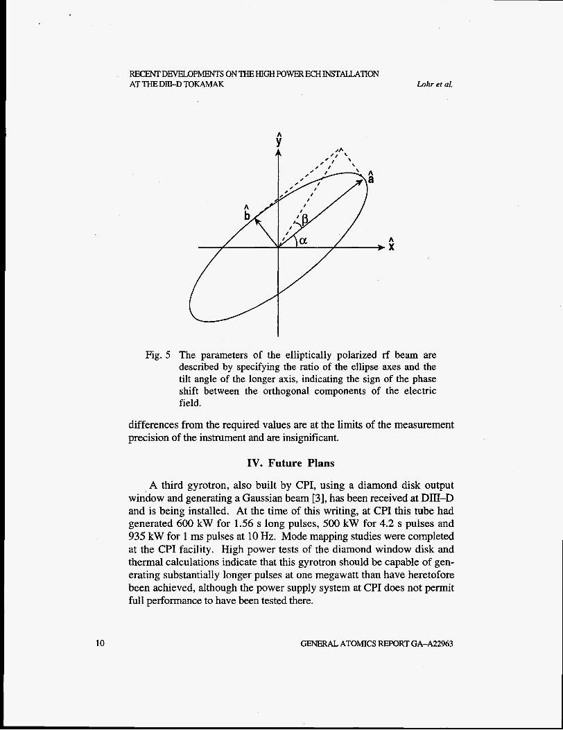
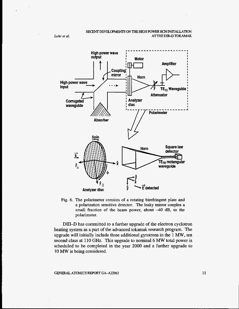
The heart of the polarimeter is a rotating birefringent plate consisting of laminated layers of dielectric tapes. A small fraction of the rf power, about 4 0 dB, is coupled to the polarimeter by a polarization insensitive leaky mirror located at a miter bend in the waveguide line. Power which has passed through the plate is measured with a horn, fundamental wave- guide and detector. The detected power is modulated by the rotating bire- fringent plate and calibration of the elements of the system using linearly polarized test signals permits the ellipticity and tilt angle of the rf beam to be measured. The time resolution of the instrument is determined by the half rotation period of the plate and has been about 25 ms for the rotation speeds used. The nomenclature used in describing the polarization of the rf beam is shown in Fig. 4 and the instrument is sketched in Fig. 5.
Several representative examples of the polarization data are shown in Fig. 6. Following the phase correction and focusing mirrors the beam is
GENERAL ATOMICS REPORT GA-A22963
Lohr et al. REGENTDEMxIPhENTSONT€EHIGHPOWEREcHINsTALLATION
ATTHEDIII-DTOKAMAK
Electron Response 6Te (ev) 150
0
-1 50 300
0
-300
II 1
0 1200 1300
Time (ms) 1400
Fig. 4. The envelope of modulated rf is shown along with the response of the ECE diagnostic at two different values of the normalized flux. The phase of the resulting Te(t) is com- pared with the measurements for three different transport theories at two different values of normalized flux. The phase of one of the transport model predictions is not con- sistent with the data at p = 0.1, but two other models are not ruled out by the data. The experimental measurements are the solid black lines and the theoretical predictions are dotted, dashed, and gray lines. The data for p = 0.1 clearly show the Te modulation, but are close to the limit of reliable detectability at presently available power levels.
nominally linearly polarized with horizontal electric field vector. The miter mirrors in the waveguide run are used to control the beam polarization at the tokamak. For one configuration of the launcher system, oblique injec- tion into the tokamak is at an angle of 19" off-perpendicular to maximize the driven current. For this injection geometry, the required b/a = -0.55 and the tilt angle for the polarization ellipse should be a = -10" to generate the highly damped X-mode. In Fig. 7 the measurements at the waveguide input and the resultant polarization of the injected rf wave, 40 m and six miter bends downstream, are plotted. The tilt angle is about 2" less than the desired value and b/a is very close to the required value. These
GENERAL ATOMICS REPORT GA-A22963 9
RECENT DEVELOPMENTS ON THE HIGH POWER ECH INSTALLATION AT THE DIII-D TOKAMAK Lohr et al.
Fig. 5 The parameters of the elliptically polarized rf beam are described by specifying the ratio of the ellipse axes and the tilt angle of the longer axis, indicating the sign of the phase shift between the orthogonal components of the electric field.
differences from the required values are at the limits of the measurement precision of the instrument and are insignificant.
IV. Future Plans
A third gyrotron, also built by CPI, using a diamond disk output window and generating a Gaussian beam [3], has been received at Dm-D and is being installed. At the time of this writing, at CPI this tube had generated 600 kW for 1.56 s long pulses, 500 kW for 4.2 s pulses and 935 kW for 1 ms pulses at 10 Hz. Mode mapping studies were completed at the CPI facility. High power tests of the diamond window disk and thermal calculations indicate that this gyrotron should be capable of gen- erating substantially longer pulses at one megawatt than have heretofore been achieved, aIthough the power supply system at CPI does not permit full performance to have been tested there.
10 GENERAL ATOMICS REPORT GA-A22963
Lohr et ai. REcENTDFNELOPhENTSONTHEHIGHFOWEREcHINSTALLATION
ATTHE DIJI-D TOKAMAK
waveiuide I
i r n l
-1111'
Analyzer ; disc
AmDlifier
r u I I I +
! TE,, Waveguide ; Attenuator I
I
Absorber
- -
Square law
waveguide P
' I / Analyzer disc
Fig. 6. The polarimeter consists of a rotating birefringent plate and a polarization sensitive detector. The leaky mirror couples a small fraction of the beam power, about 4 0 dB, to the polarimeter.
DII-D has committed to a further upgrade of the electron cyclotron heating system as a part of the advanced tokamak research program. The upgrade will initially include three additional gyrotrons in the 1 MW, ten second class at 110 GHz. This upgrade to nominal 6 MW total power is scheduled to be completed in the year 2000 and a further upgrade to 10 MW is being considered.
GENERAL ATOMICS REPORT GA-A22963 11

I
-..
V V Design Value -90 1
0.0 0.2 0.4 0.6 0.8 1.0 Time (s)
Katya gyrotron at waveguide input
-Design Value
0.04
L
E U
mtii
= a 8 .g p o w P
2 P s tc
5 I- 0.0 0.2 0.4 0.6 0.8
h
0) LI) - r 0' I
Time (s) Dorothy gyrotron at the dummy load following flat and grooved miter mirrors
Fig 7. Polarization measurements at the input to the waveguide for the Gycom gyrotron, Katya, showed good linear polarization with about 3" tilt from the horizontal. Similar measurements for the CPI gyrotron, Dorothy, made after reflection of the beam from one flat mirror and one grooved miter mirror showed linear polarization with the polarization axis rotated by about 30" due to reflection from the grooved mirror.
8 2
R s s: 8
6 P Q n ."
Lohr et aI. REcENTDEvELopMENTsONTHEHIGHpowERECHINsTALLATION
AT THE DIII-D TOKAMAK
05.014
-86 -88 ~~ -90 Design
-0.020
-1 0
Design
0.20 3 0.00 ' I
0.0 0.2 0.4 0.6 0.8 lime (s)
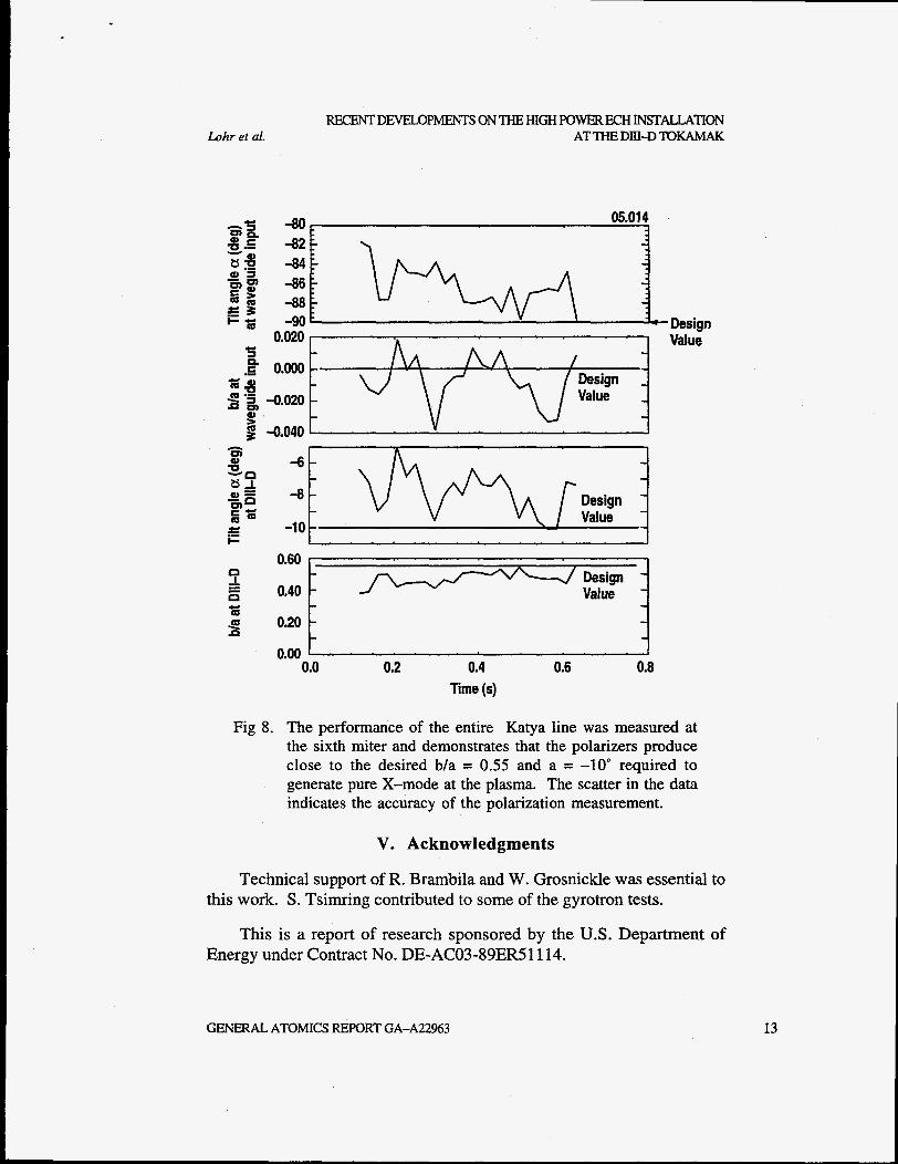
Fig 8. The performance of the entire Katya line was measured at the sixth miter and demonstrates that the polarizers produce close to the desired b/a = 0.55 and a = -10" required to generate pure X-mode at the plasma. The scatter in the data indicates the accuracy of the polarization measurement.
V. Acknowledgments
Technical support of R. Brambila and W. Grosnickle was essential to this work. S. Tsimring contributed to some of the gyrotron tests.
This is a report of research sponsored by the U.S. Department of Energy under Contract No. DE-AC03-89ER5 1 1 14.
GENERAL ATOMICS REPORT GA-A22963 13
14
RECENTDEVELOPMENTS ONTHEHIGHPOWERECHIN!XALLATION ATTHE DIU-D TOKAMAK Lohr et ai.
References
[ 11 V.E. Myasnikov et al., Proceedings of the 20th Int. Conf. on Infrared and Millimeter Waves, Orlando, 205 (1995).
[2] Kevin Felch et aZ., IEEE Transactions on Plasma Science 24, 558 (1996).
[3] Kevin Felch et al., this proceedings. [4] J.C. DeBoo et al., “Experimental Tests of Transport Models Using
Modulated ECH,” to be presented at the 17th MEA Fusion Energy Conference, Yokahama, October 1998.
[5] H. Ikezi et aZ., “Millimeter Wave Polarimeter,” submitted for publi- cation in Rev. Sci. Instrum. (General Atomics Report GA-A22856).
GENERAL ATOMICS REPORT GA-MZ963