Embed Size (px)
Citation preview

Recent Developments in Ocean ThermalEnergy
April 1980
NTIS order #PB80-201825

Library of Congress Catalog Card Number 80-600074
For sale by the Superintendent of Documents, U.S. Government Printing OfficeWashington, D.C. 20402

PREFACE
This Technical Memorandum was prepared in response to a request from
the Chairman of the Subcommittee on Energy Development and Applications of
House Committee on Science and Technology. The Committee requested that the
Office of Technology Assessment provide an update of its study of Ocean
Thermal Energy Conversion (OTEC), which was published in May 1978.1
This Technical Memorandum reviews the status of OTEC technology
developments as of April 1980. It discusses major technical accomplishments
occurring after publication of the 1978 report and principal technical
uncertainties that remain; it also attempts to summarize numerous documents
and other available information in order to provide a concise update on the
status of OTEC technology.
The Memorandum
Program staff, with
recently retired as
University of Rhode
was developed over a two-month period by the OTA Oceans
the assistance of Dr. Herman Sheets, a consultant who
the head of the Department of Ocean Engineering at the
Island. In preparing the report recent DOE and industry
reports were reviewed and there were consultations with those directly
involved in recent technology development projects.
JOHN H. GIBBONS
Director

Staff for Ocean Thermal Energy
Updated Report
Eric Willis, Assistant Director
Science, Information and Transportation Division
Robert Niblock, Oceans Program Manager
Peter Johnson, Project Director
Prudence Adler
Kathleen Beil
Carolyn Gilmore
Consultants
Gary Baham
Denzil Pauli
Herman Sheets

TABLE OF CONTENTS
1. Introduction and Findings . . . . . . . . . . . . . . . . . . . . . . . . . . . . . . .
11. The OTEC Program . . . . . . . . . . . . . . . . . . . . . . . . . . . . . . . . . . . . . . . .
111. The Ocean Resource . . . . . . . . . . . . . . . . . . . . . . . . . . . . . . . . . . . . . .
Island and Gulf Coast Resources . . . . . . . . . . . . . . . . . . . . . . . . .
Plant Ship Resources . . . . . . . . . . . . . . . . . . . . . . .............o
Summary . . . . . . . . . . . . . . . . . . . . . . . . . . . . . . . . . . . . . . . . . . . . . . .. O
I V . The Technology Base . . . . . . . . . . . . . . . . . . . . . . . . . . . . . . . . . . . . .
Significant Accomplishments . . . . . . . . . . . . . . . . . . . . . . . ● COOCC
Mini-OTEC . . . . . . . . . . . . . . . . . . . . . . .. .. .. . . .
Progress in Understanding Bio-Fouling . . . . . . . . . . . . . . . . . . .
Status of OTEC Component Development .. ..
Platforms .. .. .. .......... O..... . . . . . . . . . . . . . . . . . . .
Cold Water Pipe . . . . . . . . . . . . . . . . . . . . . . .. . . . . .
Heat Exchanger . . . . . . . . . . . . . . . . . . . . . . .....0. . . . . . . .
Power System Components .. .. .. . . . . . . . . . . . . . . . . . . .
Electrical Power Transmission Cables . . . . . . . . . . . . . .
OTEC-1 ● *oee***e 9********- ● 8**e**m*0 ● ***9*9*** ● ***9
Pilot Plant Design for an OTEC Powered Ammonia Plant
Ammonia Conversion/Fuel Cells . . . . . . . . . . . . . . . . . . . . .
Sea Solar Power-Plant Designs . . . . . . . . . . . . . . . . . . . . .
References . . . . . . . . . . . . . . . . . . . . . . . . . . . . . . . . . . . . . . . . . . . .
1
3
9
9
12
12
13
16
16
16
17
17
18
19
2 0
22
2 4
26
2 6
29
3 0

TABLES & FIGURES
Table 1: OTEC Funding Summary . . . . . . . . . . . . . . . . . . . . . . . . . . . . . . 5
Table 2: Milestones and Funding of OTEC Testing Program . . . . 6
Figure 1: Thermal Resource Availability for Hawaiian Islands, Puerto
Rico, and the Gulf of Mexico . . . . . . . . . . . . . . . . . . . . . . 11
Figure 2: Schematic of Mini-OTEC . . . . . . . . . . . . . . . . . . . . . . . . . . . . 15
Figure 3: OTEC-1 Floating Test Platform . . . . . . . . . . . . . . . . . . . . . 26
Figure 4: Baseline Pilot Plant Concept Design . . . . . . . . . . . . . . . 28
I. INTRODUCTION AND FINDINGS
OTEC is a proposed system for extracting useful energy from the solar
heat stored in vast surface waters of tropical and semi-tropical oceans.
OTEC systems aim to utilize the temperature difference between warm surface
and cold, deep ocean water to power turbines and produce electricity. Some
designs would use electricity for at-sea production of energy intensive
products such as ammonia. The federal Department of Energy is sponsoring a
major effort to develop the OTEC system as a future source of energy.
Much additional work has been done on OTEC since OTA’s original report
was issued. There have been a number of specific technical achievements and
the funding level for the program has grown from about $15 million annually
to a current annual spending pace of $40 million. Since the OTEC program
was established in the Energy Research and Development Administration five
years ago, the Federal government has invested over $100 million in it. In
addition, a number of important technical projects have been privately
funded.
The DOE is weighing data and awaiting results from additional tests
before making a key decision on whether to support the first large pilot
plant. Some critics of the DOE approach believe it is overly cautious and
that enough information is now available to justify an immediate decision to
build several pilot plants. Other critics feel that other energy
technologies are more meritorious~
MAJOR FINDINGS
The principal findings which can be summarized from this OTA analysis

- 2 -
of current OTEC technology are:
1. The technology base for OTEC has improved over the past two
years, and has consequently lowered the technical risk involved
in constructing a moderate-sized (10-40 megawatt) pilot plant.
It has not, however, developed to the point where the costs of
large commercial plants can be accurately estimated.
2 . The most significant technical accomplishments which have
occurred over the past two years are the small scale (10
kilowatt) demonstration of system feasibility of Mini-OTEC (a
barge-mounted test plant) and the improvements in several aspects
of heat exchanger performance through laboratory and sea tests.
3 . Very little has been done recently to evaluate the potential
ocean thermal energy resources available for major OTEC
commercialization; the present DOE development strategy does not
adequately consider the future resource availability.
4 . The OTEC program within DOE has grown in size and scope over the
past two years and many competent technical groups have been
involved in recent OTEC work. However, it is not certain that
the project team could adequately respond to a major acceleration
effort which would entail pilot plant construction prior to FY
82.

- 3 -
11. The OTEC Program
Within the DOE Office of Solar Technology, OTEC is one of five major
systems development projects. 2 In 1978 when OTA published its OTEC
assessment the DOE Program was just beginning to reach its present level of
attention. The 1978 OTA report described the work leading up to this
major Department of Energy program, and analyzed the status of the
technology, the economic projections, and the government funding plans.
That report presented three options of future federal funding for
consideration ranging from a no funding approach to a “systems development
funding” approach which would entail annual costs of several hundreds of
millions of dollars. The present Department of Energy program appears to be
patterned after a middle-range approach which OTA described as an “R&D
funding” approach.
Since 1978 much additional research work has been done on OTEC through
this approach. A number of specific technical achievements have been
recorded and DOE program funding has increased to almost $40 million
annually; it is planned to remain at about that level through FY 81.
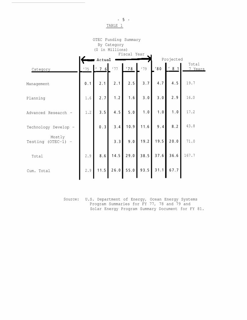
The past and future federal funding by major category is shown in a
budget breakdown in Table 1. It can be seen from the budget breakdown that
the DOE is switching emphasis from technology development to hardware
testing. In fact, the OTEC-1 test platform which is scheduled to go to sea
this June is currently using about one half of the program funds. 3
Table 2 shows the DOE OTEC-1 schedule and the schedule for an OTEC
Pilot Plant. DOE has assumed that enough information will be available by
the beginning of FY 82 to make a decision on whether to proceed with a 1O-4O
61 -689 0 - 8 0 - 2 - .

- 4 -
MW pilot plant. Such a plant would require a major increase in funding for
construction, testing and evaluation.
DOE also has plans to fund studies of competing pilot power plant
designs. Recent construction cost estimates for a 40MW pilot plant range
between 150 and $300 million and the number of pilot plants which could or
should be built is a matter of considerable debate. The proposed
legislation which is now before Congress (S-1830 and HR 5796) suggests an
accelerated program which would include construction of one or more plants
to attain a goal of 100 megawatts by 1986 and 500 megawatts by 1989. The
Congressional Budget Office estimates that such an accelerated program would
cost $1 billion over the next five years. 4
The DOE program strategy is to concentrate on the US island market
potential for early OTEC pilot and demonstration plants but not to make a
decision on the first or subsequent pilot plants until more test results are
in. Bennett Miller of DOE, testifying before the House Science and
Technology Committee in February 1980, stated that if results from OTEC-1
and other tests are encouraging and a decision is made to build an OTEC
pilot plant, it is anticipated that detailed design and construction can be
started in FY 1982 and completed in FY 1985. This pilot plant is planned to
be of a scale sufficient to demonstrate the performance and reliability of
both the total system as well as the individual components and to provide
5,6enough information for a decision to build a commercial size facility.
While the strategy of building initial systems for island markets is
considered logical by many, the pace of the program has been criticized by
several of the private companies and researchers who have been involved in
OTEC development over the past years. Some also claim that the plant ship
- 5 -TABLE 1
Category
Management
Planning
Advanced Research -
Technology Develop -
MostlyTesting (OTEC-1) -
Total
Cum. Total
OTEC Funding SummaryBy Category
($ in Millions)Fiscal Year
’75
0 . 1
1.6
1.2
2.9
2.9
’ 7 6
2 . 1
2 . 7
3 . 5
0 . 3
8 . 6
1 1 . 5
’77
2 . 1
1 . 2
4 . 5
3 . 4
3 . 3
1 4 . 5
2 6 . 0
’ 7 8
2 . 5
1 . 6
5 . 0
1 0 . 9
9 . 0
2 9 . 0
5 5 . 0
’79
3 . 7
3 . 0
1 . 0
1 1 . 6
1 9 . 2
3 8 . 5
9 3 . 5
Projected
’ 8 0
4 . 7
3 . 0
1 . 0
9 . 4
1 9 . 5
3 7 . 6
3 1 . 1
’ 8 1
4 . 5
2 . 9
1 . 0
8 . 2
2 0 . 0
3 6 . 6
6 7 . 7
Total7 Years
19.7
16.0
17.2
43.8
71.0
167.7
Source: U.S. Department of Energy, Ocean Energy SystemsProgram Summaries for FY 77, 78 and 79 andSolar Energy Program Summary Document for FY 81.

- 6 -
TABLE 2
Milestones and funding of OTEC Testing Program -
L E G E N D A BEGIN MILE$ToMcOCEAN SYSTEMS V END MILESTONEENGINEERING TEST & DEVELOPMENT o DECISION MILESTONE
A COMPLETED TASK
Source: U. S. Department of Energy, Solar Energy ProgramSummary Document FY 1981.

- 7 -
option to develop an OTEC system which could be located in the tropical
oceans to produce ammonia or other energy intensive products has not been
adequately considered in the strategy.7
Whether the program could or should be accelerated and what the
appropriate level of government involvement might be are the subjects
addressed by pending legislation. The pending legislation includes two
types of bills both of which have been introduced in the House and Senate.
The first type (S 1830 and HR 5796) requires the Department of Energy to
prepare a comprehensive plan leading to OTEC commercialization demonstration
goals. The second type (HR 6154 and S 2492) provides a licensing system for
OTEC and financial incentives for commercial and demonstration facilities.
The technical risks involved in a decision to accelerate the program are
described in section IV of this paper. It appears, however, that whether a
pilot plant is built next year or the year after will be determined more by
policy direction and management capability of the Department of Energy than
by technical considerations.8
The OTA review of past DOE funding and development work indicates that
the number of focused technical accomplishments is modest compared to the
money spent. However, the work has helped to build an institutional
capacity consisting of a number of experienced technical groups. The DOE
staff is located in several field offices as well as in Washington
headquarters. Several systems contractors also provide management support
to each of the DOE offices. The groups now involved in OTEC work are large
and diversified, include many competent technicians and some major private
companies with relevant experience. They are also spread over many
locations which makes it difficult to coordinate the diverse pieces of work.

-8 -
In their multiyear program plan, DOE has projected that, even with an
accelerated effort, large budget additions would not be needed before FY 82.
Given the present DOE management system, it does not appear likely that
OTEC pilot plant construction could be initiated much earlier than the FY 82
date now planned.

- 9 -
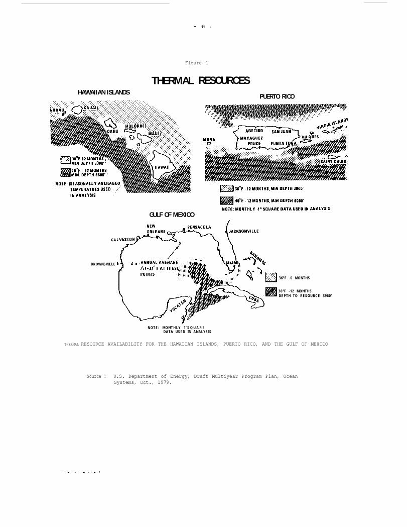
111. The Ocean Resource
OTEC plants make use of the differential temperature between the
surface and deep ocean water masses. Thus, potential energy resources are
greatest in tropical regions of the ocean where surface temperatures remain
warm (about 80oF) throughout the year, and where cold water is available at
reasonable depths.
OTA’s 1978 report noted that no one had undertaken total assessment of
the ocean’s thermal resources and their relationship to the amount and kind
of energy needed in specific locations. It did not appear that a
commercialization strategy for OTEC could be developed without, having more
detailed information and analysis of the potential thermal energy resource.
Since that report, it does not appear that DOE has completed even a
preliminary assessment of this kind which could be used in their own
9planning and commercialization of OTEC power systems.
It has been estimated that over 20 million square miles of suitable
ocean area exists worldwide for OTEC sites 1O. The DOE estimates the upper
extractable limit of this renewable resource as 200 quads (1015 Btu) per
year. (One quad per year of electrical output is roughly equivalent to
11,000 megawatts operating 100% of the time) The magnitude of the thermal
resource available to the United States for exploitation has been estimated
by DOE to be tens of quads per year. These resource numbers have not been
documented by DOE; it has not identified the sites for each estimate; and it
has not stated the assumptions used in making these estimates.11
Island and Gulf Coast Resources
Resource development strategy has also not been defined in existing DOE

- 10 -
planning documents. The DOE “island strategy” for electrical power
generation has targeted the U.S. island market as ideal for OTEC
development. OTA recommended in the 1978 report that it would be beneficial
to emphasize such specific development of island sites in the Caribbean and
Pacific Oceans.
DOE has projected incremental baseload electricity needs of U.S.
islands and the Gulf Coast. OTEC seems well-suited to the U.S. island
market because the cost of alternative incremental generation capacity is so
high for islands. The DOE strategy for commercialization also depends
heavily on penetration into the much larger continental U.S. electricity
demand in the Sunbelt region adjacent to the Gulf of Mexico. In this
market, OTEC plants must compete with baseload fossil and nuclear generating
plants.
Even though DOE future projections appear to rely heavily on developing
OTEC sites in the Gulf of Mexico, this has not been based on a detailed
analysis of the total resource that would be available to the U.S. Some
researchers have developed dynamic models of the ocean temperature in the
Gulf but these have yet to be verified. OTA made a very rough estimate of
total potential OTEC electrical production from the Gulf of Mexico in its
1978 report and concluded that about 15,000 megawatts may be available for
U.S. markets. While this estimate has also not been verified, it does
indicate that there may be some limits on resources in this particular
12, 13region.
Another question to be addressed in analyzing the Gulf of Mexico
resource is that of U.S. jurisdiction. Most of the resource now identified
is outside of 200 miles from U.S. shores and inside 200 miles from Cuban and
- 11 -
Figure 1
THERMALHAWAIIAN ISLANDS
GULF OF MEXICO
RESOURCESPUERTO RICO
GA
BROWNSVILLE
36°F .0 MONTHS
36°F -12 MONTHSDEPTH TO RESOURCE 3960’
NOTE: MONTHLY 1 o S Q U A R EDATA USED IN ANALYSIS
THERMAL RESOURCE AVAILABILITY FOR THE HAWAIIAN ISLANDS, PUERTO RICO, AND THE GULF OF MEXICO
Source : U.S. Department of Energy, Draft Multiyear Program Plan, OceanSystems, Oct., 1979.

- 12 -
Mexican coastlines. This is now considered international waters but it is
by no means easily accessible to large U.S. electrical markets.
Plant Ship Resources
The OTEC plant ship concept uses the electricity generated from the
thermal temperature differences to produce an energy intensive product such
as ammonia. This concept avoids the requirement of the electric cable from
the OTEC plant site to the user. Instead, a product will be shipped by
barge or by pipeline to the end user.
To gain maximum OTEC efficiency, there is an incentive for the plant
ship to be located where maximum temperature differences exist between the
surface and deep ocean water. These locations may be in the tropical
Atlantic or Pacific or even in the large
Hawaiian Island chain, all of these both
ocean regions near the long
regions having very large resource
potential. Thus, the plant ship may be located in international waters, a
considerable distance from the product markets of the continental United
States.
Summary
The Department of Energy has projected that OTEC will be able to serve
major U.S. markets through the use of Gulf of Mexico sited electrical
generating systems and plant ships in the tropical oceans. They have
projected 50,000 megawatts for the Gulf of Mexico and Plant ships by the
year 2010. It is not stated, however, what portion of this number would be
electrical generation or plant ships. Since the types of systems are very
different and since there is a huge difference in possible resources between
Gulf of Mexico and the tropical oceans, a strategy for resource evaluation
is urgently needed. More attention should also be given to careful analysis
of all feasible ocean thermal resources that will have an effect on OTEC
development.
- 13 -
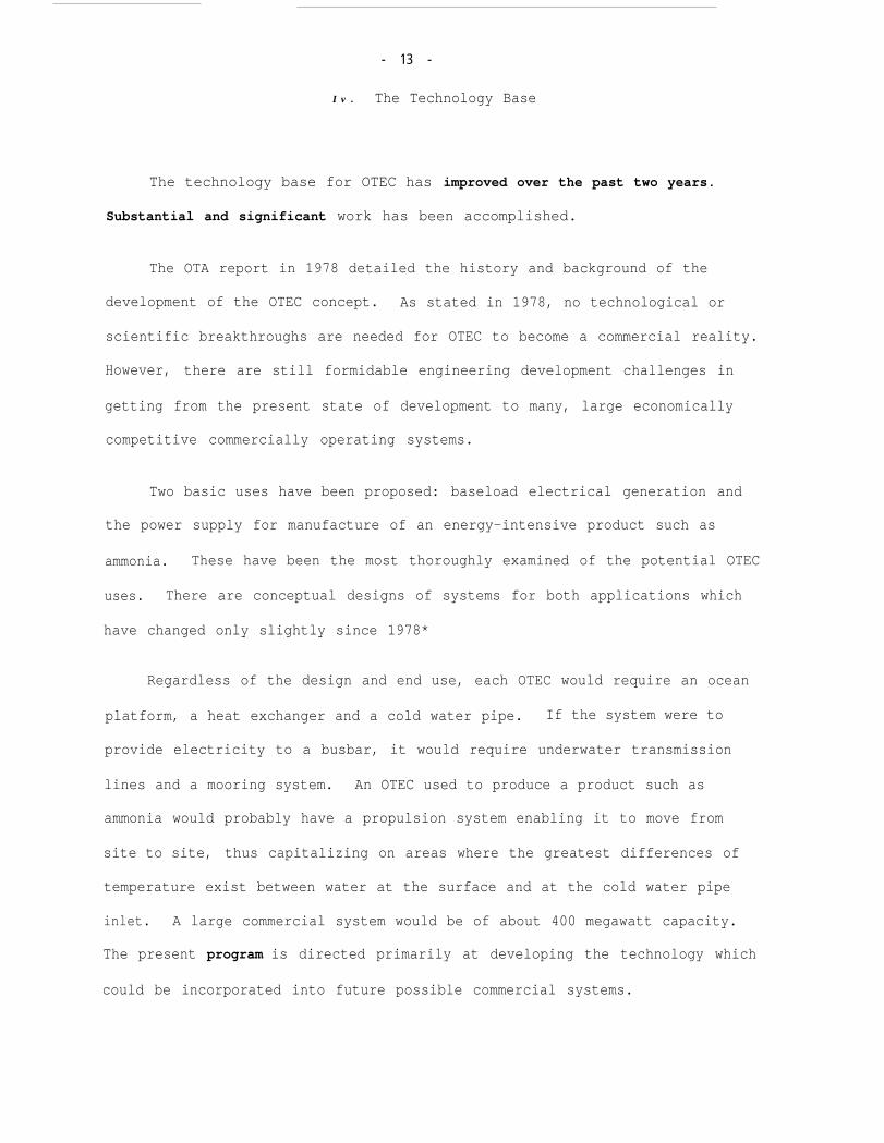
I v . The Technology Base
The technology base for OTEC has improved over the past two years.
Substantial and significant work has been accomplished.
The OTA report in 1978 detailed the history and background of the
development of the OTEC concept. As stated in 1978, no technological or
scientific breakthroughs are needed for OTEC to become a commercial reality.
However, there are still formidable engineering development challenges in
getting from the present state of development to many, large economically
competitive commercially operating systems.
Two basic uses have been proposed: baseload electrical generation and
the power supply for manufacture of an energy-intensive product such as
ammonia. These have been the most thoroughly examined of the potential OTEC
uses. There are conceptual designs of systems for both applications which
have changed only slightly since 1978*
Regardless of the design and end use, each OTEC would require an ocean
platform, a heat exchanger and a cold water pipe. If the system were to
provide electricity to a busbar, it would require underwater transmission
lines and a mooring system. An OTEC used to produce a product such as
ammonia would probably have a propulsion system enabling it to move from
site to site, thus capitalizing on areas where the greatest differences of
temperature exist between water at the surface and at the cold water pipe
inlet. A large commercial system would be of about 400 megawatt capacity.
The present program is directed primarily at developing the technology which
could be incorporated into future possible commercial systems.

- 14 -
Within a logical technology development process, the construction and
operation of a pilot plant would be very desirable to fully test a total
system design under seagoing conditions. Only after a pilot plant test
program is well underway can any accurate estimates of long term commercial
economic and technical feasibility be established. Unfortunately for such
systems as OTEC, even a pilot plant program is likely to be very costly.
OTEC technology has been developed to the stage where a moderately
sized (10-40 MW) pilot plant can probably be designed and constructed. The
most significant technical risks are in the areas of cold water pipes, heat
exchangers and electrical transmission cables. These three areas probably
need component tests and evaluations prior to building a complete system for
a pilot plant. OTEC-1 will be a floating test platform intended to evaluate
heat exchangers of one megawatt* size. Other component tests are also
planned.
OTEC development work has shown substantial progress during the last
two years. A significant event was the operation of Mini-OTEC during the
summer of 1979 in Hawaii, showing that a small OTEC system can generate net
electrical output. The progress in fouling countermeasures and the
development of heat exchangers with overall heat transfer coefficients of
about 1000 are also note-worthy.** As a result, there is now more
confidence in the prediction of OTEC technical performance.
* Plant electrical output.
** Large heat exchangers in standard electrical power plants usuallyoperate with heat transfer coefficients of less than 400.
.
- 15 -
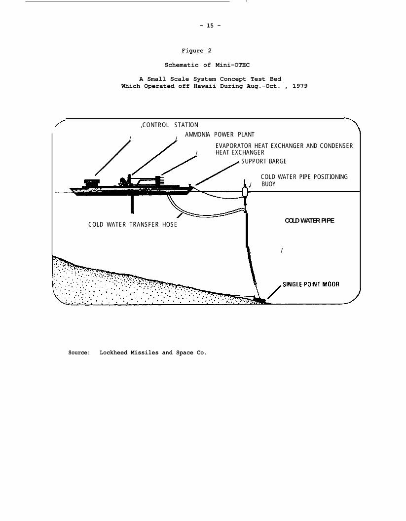
Figure 2
Schematic of Mini-OTEC
A Small Scale System Concept Test BedWhich Operated off Hawaii During Aug.-Oct. , 1979
,CONTROL STATION
/ /AMMONIA POWER PLANT
COLD WATER TRANSFER HOSE
/EVAPORATOR HEAT EXCHANGER AND CONDENSERHEAT EXCHANGER
SUPPORT BARGE
/COLD WATER PIPE POSITIONINGBUOY
, /
COLD WATER PIPE
Source: Lockheed Missiles and Space Co.

- 16 -
The following sections describe the status of the major technological
developments which make up a complete OTEC system.
Significant Accomplishments
Significant accomplishments in the OTEC program have been the operation
of Mini-OTEC and technical progress in understanding fouling and keeping
heat exchanger surfaces clean.
Mini-OTEC
The Mini-OTEC program was a joint venture costing about $2.5 million
between the State of Hawaii, Dillingham Corporation, and the Lockheed
Missile and Space Company with the U.S. Navy furnishing the barge for the
program. Mini-OTEC’s purpose was to generate net power according to the
temperature difference between the warm and cold water resource. This was
considered by many to be and the proof of principle for an OTEC system. The
cold water pipe was fabricated of 24-inch diameter polyethylene in a length
of 2150 feet. It started operation in August 1979, and ran for a period of
about 2 months. During this time, the Mini-OTEC plant operated for 2 weeks
continuously and met its design goal of 50 to 55 kilowatt gross electrical
power with 10 to 12 kilowatt net electrical power output. The 40 kilowatt
difference was used to power pumps and other auxiliaries. Heat exchangers
were fabricated of titanium and were of the plate type design. Although
this was essentially a private venture, it benefitted from a combination of
technology developed under government sponsorship and off-the-shelf
14commercial hardware.
Progress in Understanding Bio-Fouling
Another accomplishment in the OTEC program during the last three years

- 17 -
was progress in the field of micro-fouling (slime formation on heat
exchanger elements). The OTEC program has recognized the importance of
bio-fouling, corrosion, and the selection of materials for establishing the
feasibility of the entire OTEC system. It was recognized early that the
selection of materials would significantly affect cost and performance of
the entire OTEC system.
As a result of the work done during the last two years, considerably
more knowledge is available regarding micro-fouling and its accumulation for
the design of heat exchangers for long-range operation and high performance.
Information is available on a variety of cleaning methods for both the
mechanical and chemical systems. In addition, ultrasonic cleaning methods
are being investigated. Consequently, it appears that for some designs
micro-fouling can be overcome by appropriate countermeasures. 15
Status of OTEC Component Development
Platforms
Of the various OTEC components, the platform represents relatively few
technological problems. The platform for a 100-400 MW commercial OTEC power
plant is approximately the same size as very large oil drilling platforms.
The building material can be reinforced concrete or steel; such platforms
have been built in a number of industrial countries. Thus, the size and
design of the platform does not represent new concepts or technology.
However, long-life and survivability represent factors which require
additional attention. The station-keeping and mooring will require specific
data and designs for a site. A system for mooring large commercial plants
in deep water is beyond the state-of-the-art and engineering development may

- 18 -
be required. Numerous engineering studies of platforms and moorings have
been completed over the past few years; however, except for Mini-OTEC and
OTEC-1 testbeds, none have been constructed.16
Cold Water Pipe
The fabrication, deployment, and connection of the cold water pipe to
the platform will require a substantial engineering effort. For the
Mini-OTEC plant, the 24 inch polyethylene cold water pipe performed
satisfactorily. It can also be expected that for OTEC pilot plants, in the
10 to 40 megawatt range, the cold water pipe may not be a insurmountable
problem. However, for large plants (400 MW) where the cold water pipe can
be approximately 100 feet in diameter and up to 3000 feet long, it will be
considerably more difficult to design and build a pipe which can be
subjected to movements in all three axial directions and in rotation about
several axes. A substantial amount of work is presently being undertaken
for cold water pipe design and analysis. Several configurations and
materials have been proposed as feasible candidates. However, long lifetime
requirements and survivability are presenting uncertainties for the large
pipes. Dynamic loadings on the pipe due to wave action and stresses due to
platform motions are recognized as problems affecting pipe design. At this
time, rigid materials such as reinforced concrete and steel are being
analyzed together with more compliant materials such as a variety of
plastics with reinforcements and possibly nylon-reinforced rubber. It is
also quite possible that the design of the cold water pipe will be
location-dependent, similar to the cooling water discharge pipes from the
condensers of existing central station power plants. Considerable physical
oceanographic data will be required to optimize the location of the OTEC

- 19 -
plant to determine the best cold water pipe design. once a successful
design for the cold water pipe has been established, there will be a need
for production engineering and the establishment of manufacturing facilities
for the cold water pipe. Pipe materials will be an important consideration
and their selection may be affected by size and volume. Advanced handling
procedures will be needed for the large cold water pipes. It will be
important to undertake ocean testing of the cold water pipe. 17, 18
Heat Exchanger
The heat exchanger for the closed cycle OTEC plant represents the most
important component because of its size, weight, and cost. A variety of
designs have been proposed and tested. Some of these units are of the shell
and tube type with the sea water inside the tubes and the evaporating
ammonia on the shell side. Various types of heat transfer enhancement
techniques, such as flutes to promote local turbulence, have been analyzed
and tested on both the water and ammonia sides of tubular heat exchangers.
Plate heat exchangers have also been tested with ammonia side enhancement.
As a result of the many analytical and experimental data which have been
accumulated during the last two years, substantial progress has been made.
An OTEC heat exchanger with a total heat transfer coefficient of about 1000
can be expected in a modern heat exchanger design. This type of design
would have no system to enhance heat transfer on the water side so that it
can be easily cleaned for fouling purposes. This total heat transfer
coefficient is about two to three times the value attainable two or three
years ago. If the heat exchanger has no enhancement on the waterside there
is no increase in pumping power. It can be expected that the same high heat
transfer coefficient will be achieved with the plate and fin type heat
exchanger, The experimental confirmation of the high heat transfer

- 20 -
coefficient performance is a significant advancement in heat exchanger
technology. If a chemical fouling countermeasure is used, then additional
enhancement on the waterside can be used, possibly further increasing the
overall heat transfer coefficient.
At this time, titanium promises the greatest reliability for an OTEC
heat exchanger. Stainless steel and aluminum offer opportunities for less
expensive heat exchanger materials and also result in lower fabrication
cost. However, additional studies and experimentation are needed for these
materials to guarantee the same reliability and long life as titanium when
19, 20subjected to the anti-fouling countermeasures.
Other working fluids besides ammonia have been suggested. These
include various combinations of hydrocarbons and freons. For these fluids
copper-nickel could be used in the heat exchanger and thus the problems of
fouling and corrosion would be substantially reduced. Some basic work on
additional fluids may be justified so that large potential changes in
performance are not overlooked. Plastic heat exchangers have been
suggested. Such units may offer the potential of lower cost. However it may
take several years for these new materials to meet all the tests for
endurance. overall, considerable progress has been made in heat exchanger
design and performance. Its technical performance can now be estimated with
greater confidence than before. Long-range development of a lower cost heat
exchanger material will be desirable. Additional tests to optimize cleaning
methods will be needed to minimize the cost of cleaning while meeting
performance and environmental requirements.

- 21 -
Power System Components
The power turbine is a component which has received only limited
attention. This appears justified in view of such major problems as heat
exchanger design and fouling. However, the power turbine with ammonia as a
working fluid in the sizes contemplated for a commercial plant has never
been built. Since the heat of evaporation for ammonia and the enthalpy drop
through the turbine are considerably less than those of existing steam power
turbines, there may be a need to study turbine stability as well as turbine
control. In addition, it may be desirable to study the effects of ammonia
leaks on the entire power plant system.
Pumps may require special attention because they will deliver large
amounts of salt water against a relatively low head. It has been proposed
to have two or more of these pumps operating in parallel. Such high
specific speed pumps may be difficult to operate satisfactorily in parallel
unless they are provided with a special control system. The pumps and their
power requirements critically affect a total power demand to start the OTEC
plant. Considerable attention must be given to the starting requirements of
the OTEC plant and the associated power supply.
A number of alternative power cycles have been investigated. They
include the open cycle, hybrid cycle, the foam cycle, and the mist cycle.
The open cycle has some merits for small units and its ability to supply
fresh water and should be pursued. However, substantial support of the
other cycles appears no longer justified because after considerable length
of study their technical and economic success is very much in doubt. Some
other innovative power cycles may be pursued as long-range research projects
until their technical feasibility and potential economic benefits are
- 22 -
credibly evaluated. The problem of such long-range R&D) is the lack of a
central evaluation authority. There could be benefits to investigating
cycles which require smaller amounts of cold water per megawatt of
21, 22, 23electricity or systems which will reduce fouling.
Electrical Power Transmission Cables
Prior studies by the Office of Technology Assessment on the OTEC
Program pointed out the state of art of underwater electrical power
transmission citing examples of technology used in Norwegian
commercial developments have not extended that technology to
required for OTEC; nor is it expected that a commercial need
such extended technological development separate from OTEC.
waters. These
what is
will arise for
The analysis of potential power cable failure modes have been
undertaken by the Simplex Wire and Cable Company as well as Pirelli Cable
Systems, Inc. both of which have considerable experience in the design and
fabrication of underseas cables. Several designs have been prepared for
overcoming the severe problems associated with the riser cables and two
prototype cables incorporating different insulation techniques are being
manufactured for ultimate application to the 10-40 MW pilot plant. Three
cables of about 6 inches diameter each will be required. The prototypes
have to undergo extensive testing and if failures occur, will have to be
redesigned and recycled through testing. The whole process of design,
testing, redesign, retesting, preparation of manufacturing specifications,
manufacturing engineering, and further laboratory and field testing of the
cables to assure long life will take a minimum of 3 to 4 years. Plant
modifications for full cable length manufacturing and the associated detail
manufacturing engineering can then proceed followed by the actual

- 23 -
fabrication for a 100-400 MW OTEC. Manufacturing samples of the early cable
runs may well have to undergo further tests.
Thus a major development effort will be required to provide highly
reliable underwater power transmission cables to connect 1OO-4OO MW offshore
OTEC power plants to onshore consumers. Technologically , this cable must be
considered as two distinct parts: the ocean floor cable that runs from
shore to the OTEC site and the riser cable that connects the OTEC plant to
the ocean floor cable. The ocean floor portion will require fewer
technological advances as compared to the riser cable. Deeper depth
operating capability than present experience (1000 m to 1500 m as compared
to 550 m) will probably be achieved for the ocean floor cable without major
difficulty.
The technological advances required however for developing a long life
riser cable are considered to be significant. The riser cable will be
subject to continual accelerations induced by the platform motion in
response to the sea as well as its own response to ocean conditions. These
accelerations, pressures differentials, and specific weight and other
physical differences of the various elements of the riser can result in
early failure of the insulation. The development of reliable splicing
techniques for connecting the riser to the ocean floor cable and for repairs
will also require development and extensive life testing. A further
complexity will be introduced for transmission lines that are over 50 miles
long (most Gulf of Mexico sites fall within this category). These
transmission lines will probably have to be designed for very high voltage
DC rather than AC to minimize power losses. This will affect the selection
of insulations as well as the internal cable construction. In view of the
.
- 24 -
foregoing, it will be necessary that the cable design take into account
system aspects such as expected sea conditions, Platform movement and cable
laying techniques and capability, as well as the techniques of attachment of
the riser cable to the platform. Concepts of integration of the riser cable
with the platform cold water pipe will have to be weighed against
repairability , maintenance requirements, and technological trade-offs.
If several OTEC plants are to be installed within the next decade there
may not be enough cable manufacturing facilities in the United States or
possibly in the world to provide enough cables for the OTEC programs. New
cable manufacturing facilities in a coastal area may be needed together with
the requirements for cable laying ships or barges. With modern engineering
methods it may be possible to substantially reduce the cost of cable
manufacturing and cable laying. 24, 25, 26, 27
OTEC-1
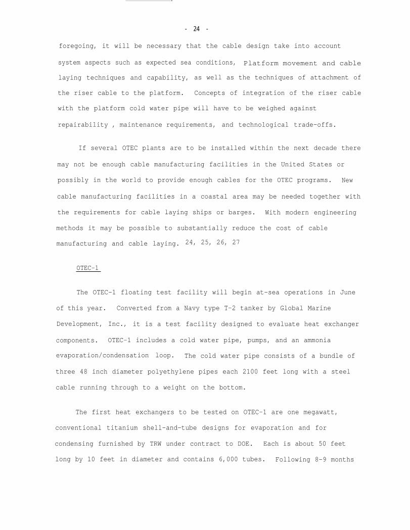
The OTEC-1 floating test facility will begin at-sea operations in June
of this year. Converted from a Navy type T-2 tanker by Global Marine
Development, Inc., it is a test facility designed to evaluate heat exchanger
components. OTEC-1 includes a cold water pipe, pumps, and an ammonia
evaporation/condensation loop. The cold water pipe consists of a bundle of
three 48 inch diameter polyethylene pipes each 2100 feet long with a steel
cable running through to a weight on the bottom.
The first heat exchangers to be tested on OTEC-1 are one megawatt,
conventional titanium shell-and-tube designs for evaporation and for
condensing furnished by TRW under contract to DOE. Each is about 50 feet
long by 10 feet in diameter and contains 6,000 tubes. Following 8-9 months

- 25 -
allocated to tests on this design, it is planned that the ship will be
returned to port, the heat exchangers removed, and up to four smaller 0.2
megawatt units of advanced design installed for tests.28
The actual expenditures for the design and conversion of OTEC 1 are now
projected to be about $7 million more than the original budgeted amount of
$33 million. This was caused by a number of factors including difficulties
encountered after the mothballed tanker was carefully inspected to see which
systems needed replacement. Such an overun is not unusual in large
engineering development projects and it might be expected that future
overuns could occur when the much more difficult OTEC technology development
and testing work is undertaken.
To what extent the results of OTEC-1 tests are necessary for the design
and construction of a pilot plant is a matter of considerable debate. At
present, it is not possible to determine because DOE has not defined which
pilot plant concept or strategy they wish to pursue. If a concept for a
pilot plant had been selected, a logical program of component testing aboard
a test platform could be developed. For some pilot plant concepts OTEC-1
may have limited usefulness. For others, component testing could include
heat exchangers, cleaning methods, parts of cold water pipes and electrical
riser cables. It now appears that only one type of heat exchanger, which
may or may not be suitable for a pilot plant, will be tested on OTEC-1 prior
to FY 82.
It is too early to report any accomplishments from the OTEC-1 test
platform but it appears that most of the hardware has been built on schedule
and by 1981 some initial at-sea heat exchanger test results should be
available.
- 26 -
Figure 3
HELlCOPTER DECK
--4 EVAPORATOR\
COLD-WATER PIPE CONDENSER\ ~
iiiWARM-WATER
INTAKE
OTEC-1 FLOATING TEST PLATFORM being designed and built water pipe and ammonia evaporation, condensation, and recir-Global Marine Development, Inc. and TRW is a converted culation. TRW designed the heat exchanger under a separate
Navy tanker. It will be used to evaluate different (OTEC compo- contract with the Department of Energy. The ship will be an-nents and operation of the heat exchange loop, including cold chored off Ke-ahole Point near the island of Hawaii.
Source: Quest, New Technology at TRW Defense and Space Systems Group,Autumn, 1979.

- 27 -
A conceptual integrated design of a 40 megawatt pilot plant has been
completed under contract to DOE by the Applied Physics Laboratory of Johns
Hopkins University using the APL plant ship concept. This design calls for
a concrete platform approximately 450 feet long of almost 100,000 tons
displacement. It’s four modules would generate 10 megawatts each. A
lightweight concrete cold water pipe 30 feet in diameter and 3,000 feet long
with four cold water pumps is proposed. The design can be either a moored
plant with an electrical cable to shore or a grazing plant and include an
ammonia conversion plant. The Johns Hopkins Applied Physics Lab is now
completing a report on this design which includes a complete system concept
design. Heat transfer tests of some laboratory conducted ultra-sonic
cleaning tests of the heat exchanger indicates promising results. A section
of the cold water pipe is being fabricated for test. APL has estimated the
cost of a 40 MW pilot plant with no profit or contingencies to be $140 -
$160 million.29
Ammonia Conversion/Fuel Cells
The prospect for developing an OTEC system for operating in the
tropical coceans has led to design studies of ammonia conversion systems for
these plants and of fuel cells which may be powered by ammonia produced by
these plants.
APL’s first OTEC Plant Ship concept used the solid polymer electrode
(SPE) electrolysis system to produce hydrogen from seawater. The cells use
electricity to manufacture hydrogen at voltages of 1.6 to 1.9 volts (direct
3 0current).
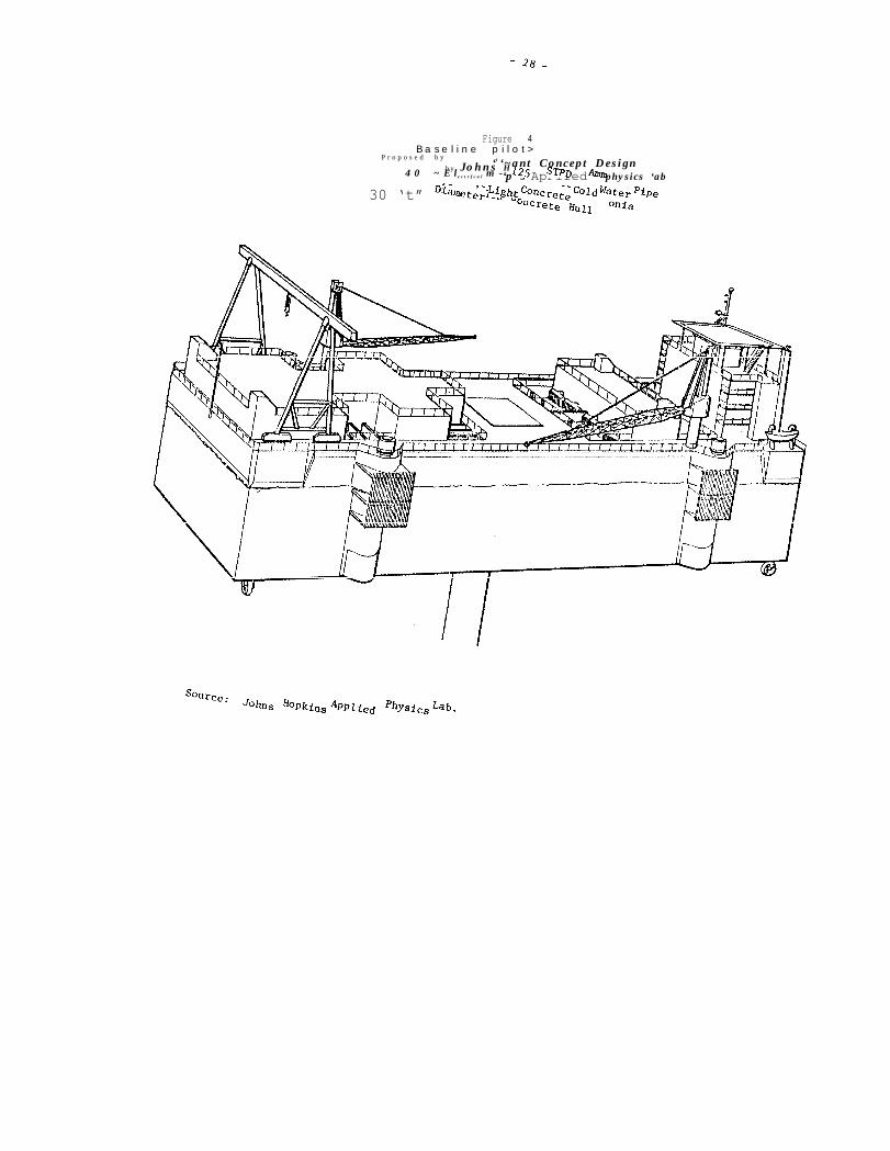
Figure 4B a s e l i n e p i l o t >
P r o p o s e d b y
by J o h n s H ~1‘ t ‘~ant Concept Design‘p ‘s ApPlied physics ‘ab4 0 ~ E le c t r f c a l m - 125 STPD &
60,000 Ton ~‘ncrete nU~l Ollia
30 ‘t” ‘i-ter ‘ight concrete cold ‘ater ‘iP’=
‘oUrce:‘Ohns %Jkins @Plied phYsic5 Lab.

- 29 -
Currently, General Electric has a 50 KW unit for generating electricity
from hydrogen operating in the laboratory. The electrodes on these cells
are made of platinum and blends of other noble metals. They have in some
instances operated over 20,000 hours with negligible deterioration. GE iS
working on ways to reduce the noble metal content of the cell electrodes. 31
Avery has published a paper including cost estimates for an
ammonia-OTEC fuel cell cycle using SPE cells. The paper claims a 50-55%
efficiency of the SPE fuel cell cycle using present systems going up to 60
to 65% achievable at low current densities with further R&D effort. While
such systems may be possible in the future, considerable R&D effort will be
needed.32
Sea Solar Power-Plant Designs
A somewhat different approach to OTEC plant design has been suggested
by Sea Solar Power, Inc. of York, Pennsylvania. They have concentrated R&D
attention on a system using a halocarbon instead of ammonia as a working
fluid and incorporating their patented high performance heat exchanger.
They have built and tested a small working model and have prepared a
conceptual design for a 100 megawatt plant. Much of their work has been
funded internally. Some of their concepts deserve development attention in
future OTEC designs because breakthroughs in heat exchangers could be the
most significant factor for future economic viability.33

- 30 -
References
10 U.S. Congress, Office of Technology Assessment, Renewable Ocean Energy, Sources - Ocean Thermal Energy Conversion, May 1978.
2. U.S. Department of Energy, Solar Energy Program Summary Document FY1981, January 1980.
3. U.S. Department of Energy, Ocean Energy Systems, Fiscal Year 1979,Program Summary.
4. U.S. Congress, Ocean Thermal Energy Conversion, Research Developmentand Demonstration Act, Senate Report No. 96-501, December 14, 1979.
5 . Statement of Bennett Miller before the House Science and TechnologyCommittee Subcommittee on Energy Development and Applications, February13, 1980.
6. U.S. Department of Energy, Briefing on OTEC Program Status by W.Richards, February 14, 1980.
7 . Johns Hopkins, Applied Physics Laboratory, Briefing on status of 40 MWpilot plant design studies, February 25, 1980.
8 . U.S. Department of Energy, Draft Multiyear Program Plan, OceanSystems, October 1979.
9 . Letter; Lloyd F. Lewis, Division of Planning and Technology Transfer,DOE, April 5, 1979, and Memo, Lloyd Lewis to OTA, February 15, 1980.
10. Letter from W.H. Avery, Applied Physics Laboratory, Johns HopkinsUniversity, to Russell W. Peterson, Office of Technology Assessment,August 25, 1978.
110 Multiyear Program Plan, Executive Abstract for Ocean Systems,Department of Energy, Division of Central Solar Technology, OceanSystems Branch, October 1979.
12. Renewable Ocean Energy Sources, Part 1 Working Papers - EnergyConversion, The Baham Corporation, Prepared for the Office ofTechnology Assessment, May 1978.
13. Renewable Ocean Energy Sources, Part 1 Ocean Thermal Energy Conversion,The Office of Technology Assessment, May 1978.
14. Technical briefing to OTA by F.E. Naef of Lockheed Corp. , Washington,D.C., March 10, 1980.
150 Phone conversation between Dr. Herman Sheets, Analysis and Technology,Inc. , and Dr. Norman Sather and Dr. Joseph Draley, Argonne NationalLaboratory, March 1980.
- 31 -
1 6 .
1 7 .
1 8 .
1 9 .
2 0 .
2 1 .
2 2 .
2 3 .
2 4 .
2 5 .
2 6 .
2 7 .
2 8 .
2 9 .
3 0 .
3 1 .
U.S. Department of Energy, Draft Report of the Working Groups, 6th OTECConference, (Washington, D.C.: June 19-22, 1979), unpublished.
Presentation to the Ocean Energy Systems Council by ETEC, “EquipmentExperiment Instrumentation and Data Reduction on OTEC 1“, La Jolla,California November 13-14, 1979.
TRW Systems and Energy, Cold Water Pipe Preliminary Design Study, FinalReport, (Redondo Beach, California: TRW, November 20, 1979).
Phone conversation between Dr. Herman Sheets, Analysis and Technology,Inc. and Dr. Norman Sather, Argonne National Laboratory, March 1980.
Phone conversation between D. Pauli, OTA and Ralph Mitchell, HarvardUniversity, April 11, 1980.
University of Oklahoma, School of Chemical Engineering, Use of Mixturesas Working Fluids in Ocean Thermal Energy Conversion Cycles--Phase II.,(Norman, Oklahoma: University of Oklahoma, February 1978).
U.S. Department of Energy, Draft Report of the Working Groups, 6th OTECConference, (Washington, D.C.: June 19-22, 1979), unpublished.
Oak Ridge National Laboratory Report of the Proceedings of the OTECAlternative Cycles Contractors Information Exchange Meeting, December1978.
Bamford, Thomas B. et al, Riser Segment Design of Underwater ElectricPower Transmission Cable System, Simplex Wire and Cable Company,(Portsmouth, New Hamphire: 1978).
Rumbaugh, Jeffery H. et al. , “Thermal Energy Conversion: Tapping theSea Depth”, Spectrum, Vol. 16, No. 8 (August 1979).
Phone conversation between D. Pauli, OTA, and Robert E. Perry,Electrical Power Research Institute, April 10, 1980.
Phone conversation between D. Paul, OTA, and E. Ken Roberts, SimplexWire and Cable Company, April 11, 1980.
Douglass, R.H. , OTEC: Solar Energy from the Sea, in Quest-NewTechnology at TRW, Autumn 1979.
Johns Hopkins Applied Physics Lab, OTEC Briefing at Columbia Maryland,February 25, 1980.
Avery, W.H. , R.W. Blevins, G.L. Dugger, and E.J. Francis, “ExecutiveSummary, Maritime and Construction Aspects of Ocean Thermal EnergyConversion (OTEC) Plant Ships,” Applied Physics Laboratory, SR 76-1A,April 1976.
Telecon: G. Baham, OTA to L. Nuttal, General Electric Company, March14, 1980.

- 32 -
32. Avery , W.H. , “The OTEC Contribution to Energy Needs of all Regions ofthe U.S. ,“ undated.
33. Spencer R. Liverant and James H. Anderson Jr., Sea Solar Power Inc.,OTEC briefing to OTA, Washington, D.C., March 11, 1980.
U.S. GOVERNMENT PRINTING OFFICE : 1980 0 - 61-689