Embed Size (px)
Citation preview
Recent development of a point positive muon source by laser excitation of
muonium atoms
Introduction Experiment at the RIKEN-RAL Muon facility Future prospect
Yasuyuki Matsuda (Muon Science Laboratory, RIKEN)
for slow muon collaboration
Slow muon collaboration
Y. Miyake (KEK) K. Shimomura (KEK) S. Makimura (KEK) K. Nagamine (KEK) J.P. Marangos
(Imperial College, UK)
Y. Matsuda (RIKEN) P. Bakule (RIKEN) P. Strasser (RIKEN) K. Ishida (RIKEN) T. Matsuzaki (RIKEN) M. Iwasaki (RIKEN)

Applications of muon beam
Material Science : SR study with surface muon beam (30MeV/c). Very successful. By
far, the most popular way to use muon beam. But, its application has been limited to bulk material due to wide
momentum dispersion and large beam size. Muon-catalyzed fusion Fundamental Physics
Search of rare decay mode and precise measurement of know decay mode
Muonium and muonic atom for study of symmetries, nuclear structure, etc…
neutrino source, muon collider requires muon beam with better quality.
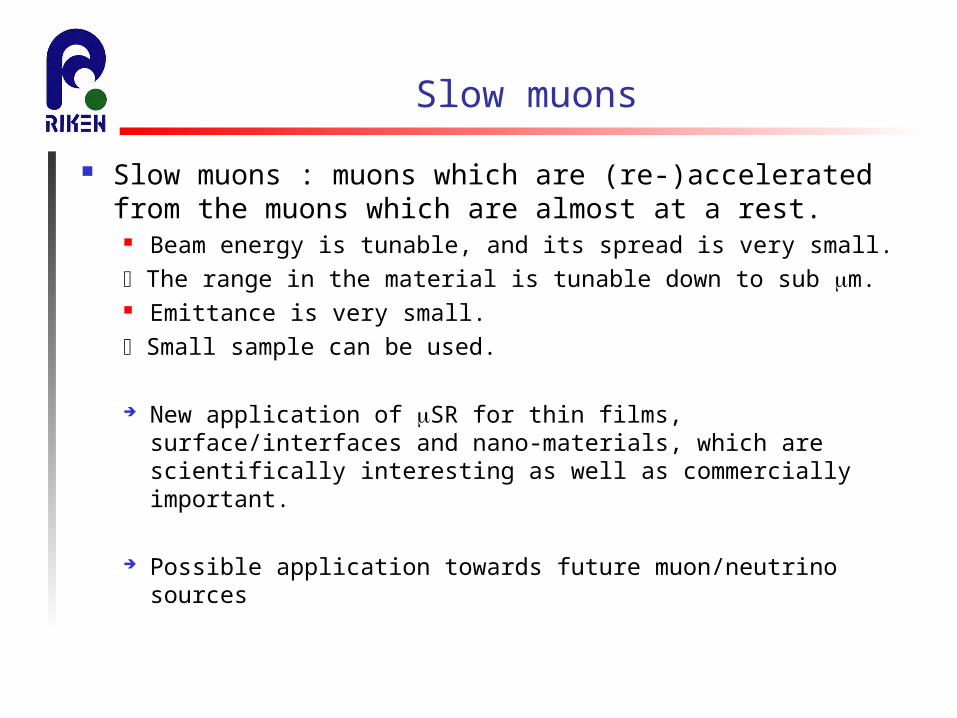
Slow muons
Slow muons : muons which are (re-)accelerated from the muons which are almost at a rest.
Beam energy is tunable, and its spread is very small.
The range in the material is tunable down to sub m. Emittance is very small.
Small sample can be used.
New application of SR for thin films, surface/interfaces and nano-materials, which are scientifically interesting as well as commercially important.
Possible application towards future muon/neutrino sources
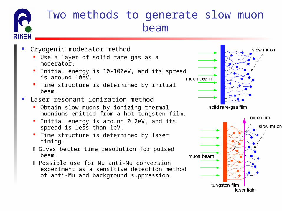
Two methods to generate slow muon beam
Cryogenic moderator method Use a layer of solid rare gas as a moderator. Initial energy is 10-100eV, and its spread is
around 10eV. Time structure is determined by initial beam.
Laser resonant ionization method Obtain slow muons by ionizing thermal
muoniums emitted from a hot tungsten film. Initial energy is around 0.2eV, and its spread is
less than 1eV. Time structure is determined by laser timing. Gives better time resolution for pulsed beam. Possible use for Mu anti-Mu conversion experiment
as a sensitive detection method of anti-Mu and background suppression.

Previous slow muon experiments
PSI slow muon beam line Cryogenic moderator method
Efficiency close to 104
Initial beam energy spread is about 10eV
Yielded about 700 /sec (*1)
DC source A timing counter needs to be
inserted in the transport line for SR study
Successful operation since 1993
ISIS EC slow muon beam line Applied cryogenic moderator
method to a pulsed muon source.
Yielded about 1 /sec (*2)
Pulsed source Time-of-flight showed time
resolution was about 90nsec (FWHM), according to ISIS beam pulse width.
Better energy resolution than PSI thanks to absence of a trigger counter.
Currently defunct.(*1) E. Morenzoni et al. Physica B 326(2003)196(*2) K. Trager et al. Physica B 289-290(2000)662

PSI slow muon beam line
E. Morenzoni et al. Hyperfine Interactions 106(1997)229
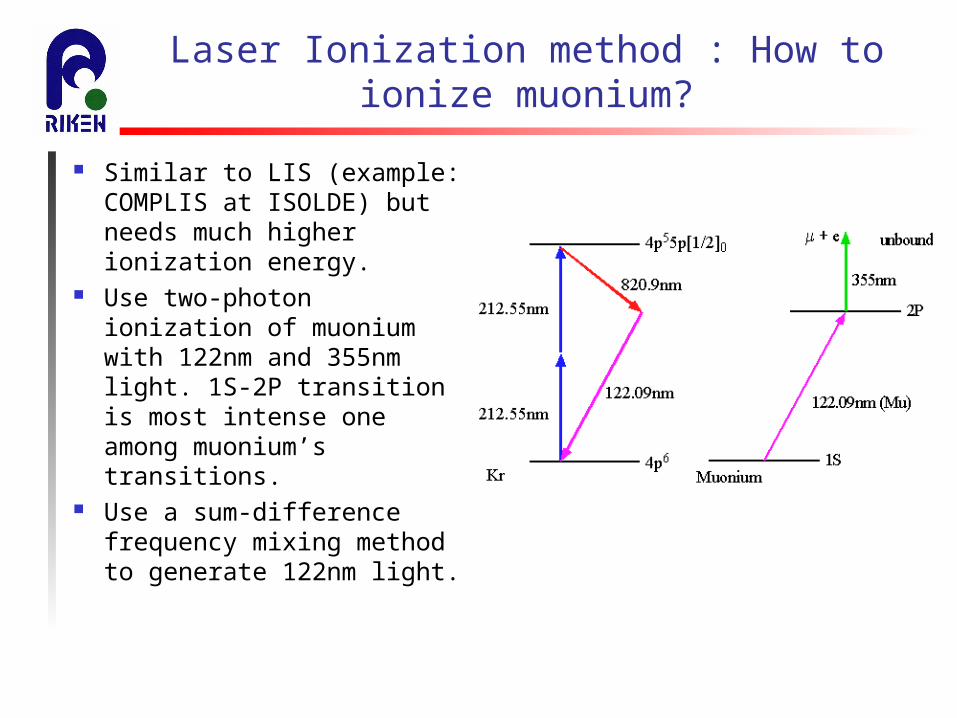
Laser Ionization method : How to ionize muonium?
Similar to LIS (example: COMPLIS at ISOLDE) but needs much higher ionization energy.
Use two-photon ionization of muonium with 122nm and 355nm light. 1S-2P transition is most intense one among muonium’s transitions.
Use a sum-difference frequency mixing method to generate 122nm light.
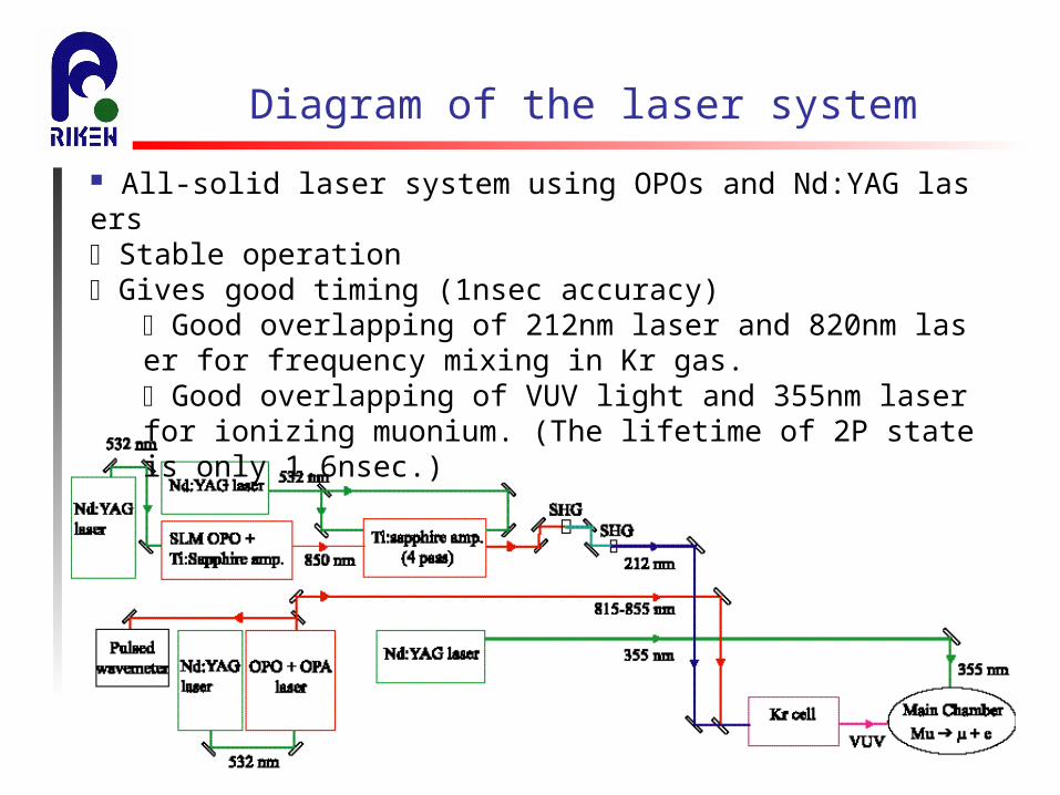
Diagram of the laser system
All-solid laser system using OPOs and Nd:YAG lasers Stable operation Gives good timing (1nsec accuracy)
Good overlapping of 212nm laser and 820nm laser for frequency mixing in Kr gas. Good overlapping of VUV light and 355nm laser for ionizing muonium. (The lifetime of 2P state is only 1.6nsec.)
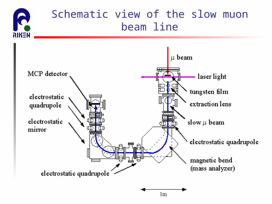
Schematic view of the slow muon beam line

Schematic view of the slow muon beam line
High purity Tungsten film (45m; 87mg/cm2)Tungsten degrader (20m; 39mg/cm2)
SUS foil (50m; 40mg/cm2)
Kapton foils
Ionizing Lasers
Main Chamber
Degrader chamber
(1x10 11 hPa)
(1x10 hPa)
surface muons
slow muons
Port 3 beam line(1x10 hPa)

The first observation of slow muons at the RIKEN-RAL muon facility (July 2001)
A clear peak on TOF spectrum was observed at the position which corresponds slow muon at the accelerating voltage of 7.5kV.
Measured magnetic field of the bending magnet corresponds to the correct muon mass.
Count rate was 0.03 /sec. (too small!)

Improved slow muon generation at the RIKEN-RAL muon facility (April 2003)
The yield of slow muon (3.3 slow /sec) is 100 times more than that obtained in July 2001, and larger than the previous experiment at the EC muon beam line with cryogenic moderator method.
The time diversion of slow muon beam is about 10ns (FWHM), whereas the cryogenic moderator experiment gave about 100nsec.

Improvements during 2001/02
laser system improvement Improved VUV laser intensity by phase-matching. Installed image relays for pumping YAG resulted an improved profile. Installed an image relay for 355nm laser, eliminating hot spots. Installed a cylindrical telescope to convert 355ns laser’s beam profile
to perpendicular shape (3x12mm) to maximize overlapping between 355nm and VUV lasers.
beam line improvement Removed a small aperture, which was reducing initial beam intensity. Target thickness was reduced so that we can maximize the number of
muons stopped at the rear-surface of the target. Beam line magnet was tuned to maximize Port 3 intensity while
keeping same intensity at Port 2.

What is phase matching?
P=0((1)E+(2)E2+(3)E3+…)
P: polarization (dipole moment per unit volume)
(1): linear susceptibility
(2): second order nonlinear susceptibility
(3): third order nonlinear susceptibility
Phase-matching condition: phase velocity of generated light equals to that of induced nonlinear polarization.
efficient nonlinear process

Kr-Ar phase matching at muonium 1S-2P frequency
Enhancement of VUV generation due to phase matching of Kr gas with Ar buffer gas was observed with slow muon yield.
The ratio of Kr and Ar buffer gas (1:6) agrees with theoretical calculation.
0
0.5
1
1.5
2
2.5
3
3.5
4
4.5
5
0 50 100 150 200 250
Ar partial pressure (hPa)
slow
muo
n yi
eld
(cou
nts/
Ksp
ills
)
Kr 20hPa + Ar
212.55nm
212.55nm820.9nm
122.09nm
Kr / Kr+Ar

Muon stopping range tuning
0
0.5
1
1.5
2
2.5
3
3.5
0 10 20 30 40 50
Kapton thickness [mg/cm2]
coun
ts/k
spill
s
Preliminary
The thickness of the degrader is optimized to give maximum yield of slow muons.
Measured range width (5.5% FWHM) reasonably agrees with expected value.
Kapton foils
Ionizing Lasers
surface muons
slow muons

Laser timing dependence
0.0
5.0
10.0
15.0
20.0
25.0
30.0
35.0
0 1000 2000 3000 4000 5000 6000laser irradiation time from the arrival of the 1st pulse (nsec)
slow
muo
ns/K
spil
ls
Relative timing between the initial beam’s arrival time and laser irradiation time was scanned.
A double-pulse structure of the initial muon beam is clearly observed.
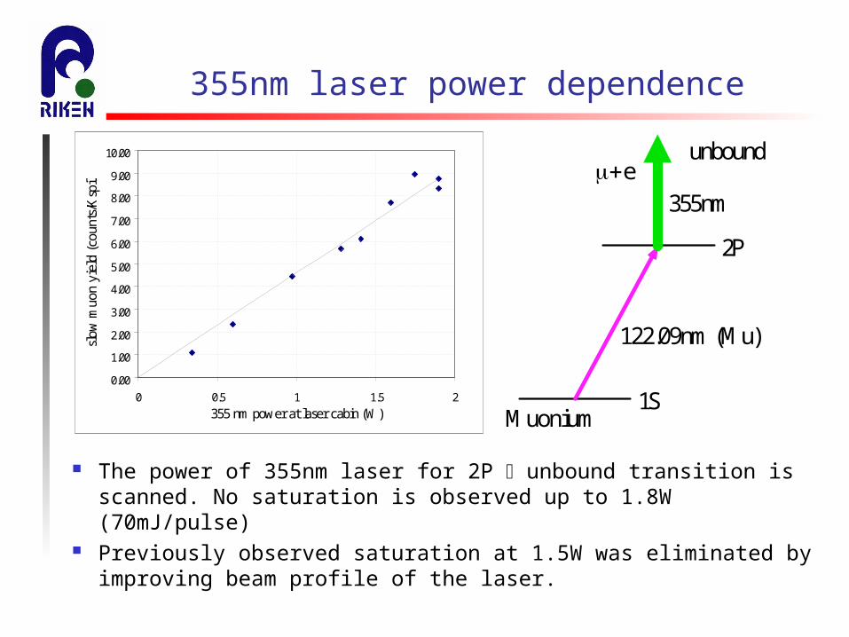
355nm laser power dependence
0.00
1.00
2.00
3.00
4.00
5.00
6.00
7.00
8.00
9.00
10.00
0 0.5 1 1.5 2355 nm power at laser cabin (W)
slow
muo
n yi
eld
(cou
nts/
Ksp
ills)
The power of 355nm laser for 2P unbound transition is scanned. No saturation is observed up to 1.8W (70mJ/pulse)
Previously observed saturation at 1.5W was eliminated by improving beam profile of the laser.
1S
2P
unbound
355nm
122.09nm (Mu)
Muonium
e
820nm laser frequency dependence
0.00
1.00
2.00
3.00
4.00
5.00
6.00
7.00
8.00
9.00
818.50 819.00 819.50 820.00 820.50 821.00 821.50 822.00
M3000 wavelength on burleigh (nm)
Slo
w m
uon
yiel
d (c
ount
s/K
spil
ls)
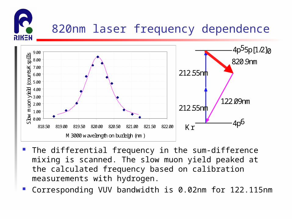
The differential frequency in the sum-difference mixing is scanned. The slow muon yield peaked at the calculated frequency based on calibration measurements with hydrogen.
Corresponding VUV bandwidth is 0.02nm for 122.115nm
212.55nm
212.55nm
4p6
4p55p[1/2]0820.9nm
122.09nm
Kr

Measurement of MCP’s efficiency
A vacuum flange at the end of the MCP chamber was replaced with a flange with 100m SUS film.
A scintillator telescope was installed nearby the film to detect decay positrons from the film.
By measuring “enhancement” in scintillator’s spectrum, the number of slow muons stopped at the film was estimated.
The efficiency of MCP was evaluated to be about 66%.

Efficiency of slow muon generation
Observed slow muon signal : 3.3 /sec
(MCP efficiency 66%) 5.0 /sec
(Decay in flight 43%) 8.6 /sec
(Transport efficiency unknown. assume 100%)
>8.6 /sec at the source
Initial surface muon beam : 1.0x10⁶ /sec
Efficiency 8.6/1.0x106 = 8.6x10⁶ (still low…)

Issues to be addressed
Improvement of muonium ionization efficiency. Improvement in laser power
both 355nm and VUV lasers are not saturating muonium transition. Improvement of pumping laser’s profile will benefit frequency-
quadrupling with BBO crystals Improvement of OPO frequency conversion system
Stable operation of laser system is the key for the application of slow muon beam.
Improvement of muon to muonium conversion efficiency. optimizing target material, its thickness, temperature… Possible use of cyclotron trap with a thinner tungsten film

Cyclotron Trap
PSI & LEAR application Winding up the range path of stopping particles inside a weak
focusing cyclotron field. It has been used for producing low energy negative muons beams, pions and anti-protons.
Moderator can be gas (typically ~1mbar Hydrogen), or thin metal foils.
Application for positive muons have been limited because of high capture rate of electron.
Cyclotron trap + laser ionization Can expect increase of muon stopping density at the near-surface of
Tungsten foil. We will lose muon polarization. This will limit application for SR,
but is good for Mu anti-Mu oscillation experiment. Recover muon polarization with polarized laser light?

Future plans
Beam study Beam profile measurement ( Segmented MCP, Slit, emittance measurement)
SR study Scintillator telescopes installation around the MCP chamber. Helmholtz coil installation
Thinking of fundamental physics… Mu anti-Mu conversion experiment : double coincidence between laser irradi
ation and anti-Mu detection will reduce background significantly. PSI experiment accumurated 5.7x10¹⁰ muonium decays. We need significant i
mprovement of slow muon yield. Muon intensity improvement : J-PARC, new proton driver, new design of
capture channel. Muon to muonium conversion improvement : cyclotron trap Muonium ionization improvement : laser performance.

Time table (optimistic)

Summery
We have successfully generated slow muon beam with laser resonance ionization method at the RIKEN-RAL muon facility. The yield has improved by 100 times compared to previous result obtained at July 2001.
Several improvement plans for more efficient VUV generation are under way to increase efficiency of slow muon conversion, which will make slow muons available to material sciences.
Slow muon setup can be used as a prototype of Mu anti-Mu experiment. We can expect reduced background by coincidence between laser irradiation and anti-Mu detection.
Measurement of beam profile and emittance is planned during 2003/2004. There is a possibility for application to neutrino/muon factory, but its feasi
bility largely depends on improvements of laser system in terms of stability and efficiency.

--------


![Muonium Klaus P. Jungmann arXiv:physics/9809020v1 … · arXiv:physics/9809020v1 [physics.atom-ph] 15 Sep 1998 Muonium Klaus P. Jungmann Physikalisches Institut, Universita¨t Heidelberg](https://img.pdfslide.us/doc/110x75/5b3ad8567f8b9a0e628c0f9c/muonium-klaus-p-jungmann-arxivphysics9809020v1-arxivphysics9809020v1-physicsatom-ph.jpg)