Embed Size (px)
Citation preview
Recent Advances in Percutaneous Cardioscopy
Yasumi Uchida
Published online: 12 May 2011# The Author(s) 2011. This article is published with open access at Springerlink.com
Abstract Percutaneous cardioscopy, using high-resolutionfiberoptic imaging, enables direct visualization of thecardiac interior, thereby enabling macroscopic pathologicaldiagnosis. Percutaneous cardioscopy has demonstrated thatthe endocardial surface exhibits various colors characteris-tic of different heart diseases. This imaging modality cannow be used for evaluation of the severity of myocardialischemia, and staging of myocarditis. Myocardial bloodflow recovery induced by vasodilating agents or percuta-neous coronary interventions can be clearly visualized.Morphological and functional changes in the cardiac valvescan also be evaluated. Cardioscope-guided endomyocardialbiopsy enables pin-point biopsy of the diseased myocardi-um. Recently, dye-image cardioscopy and fluorescencecardioscopy were developed for evaluation of the subendo-cardial microcirculation. Cardioscope-guided intracardiactherapies such as myotomy, myectomy, valvulotomy, andtransendocardial angiogenic and myogenic therapy havebeen trialed using animal models in anticipation of futureclinical applications. Percutaneous cardioscopy has thepotential to contribute to our understanding of heart disease,and to assist in guidance for intracardiac therapies.
Keywords Percutaneous cardioscopy . Dye-stainingcardioscopy . Fluorescence cardioscopy . Cardioscope-guided endomyocardial biopsy and intracardiac surgery
Introduction
Direct observation of changes in the beating heart waspreviously beyond the scope of any available imaging
modalities. Percutaneous cardioscopy, using high-resolutionfiberoptic imaging, enables direct visualization of the cardiacinterior, thereby enablingmacroscopic pathological diagnosis.This imaging modality is now clinically employed not onlyfor diagnosis of myocardial and valvular disease, but also forevaluation of interventional and surgical therapies. In thisarticle, the past, present, and future prospect of this promisingimaging modality will be presented.
Developmental History of Percutaneous Cardioscopy
Intracardiac observation using a rigid cardioscope inanimals was performed by Allen et al. in 1922 [1] and byHarken et al. in 1943 [2]. In 1956, Sakakibara et al. [3]employed a rigid cardioscope to observe a septal defectduring open-heart surgery. They also observed aortic valvesusing the same cardioscope in 1958 [4].
Difficulties in producing a thin endoscope that can safelybe introduced percutaneously into the cardiac chambers,and equipment that can displace blood, meant that about29 years elapsed before Uchida and his coworkerssuccessfully performed percutaneous cardioscopy inpatients [5, 6]. Although this new modality of diagnosis isnow performed routinely in a few selected institutions, ithas yet to be adopted on a global scale.
In 1975, a 9-F fiberscope was developed in collaborationwith Olympus Corporation, Tokyo. This cardioscope wasintroduced through an 11-F hard-tipped guiding catheterinto a canine left ventricle, but was abandoned due tomarked damage to the endocardial surface. In 1976, a 10-Fballoon-tipped guiding catheter was developed. This cath-eter allowed the passage of a 6-F fiberscope. However, thiscardioscope also had to be abandoned because the balloonbecame frosty during use due to the temperature differencebetween the saline used for balloon dilatation and the bloodin the ventricle. In the same year, a fiberscope was devised
Y. Uchida (*)Japan Foundation for Cardiovascular Research,2-30-17, Narashinodai,Funabashi 274–0063, Japane-mail: [email protected]
Curr Cardiovasc Imaging Rep (2011) 4:317–327DOI 10.1007/s12410-011-9092-6

with a balloon at its tip. This fiberscope had a central lumenthrough which warmed saline at body temperature could beinfused to dilate the balloon. The balloon was pushedagainst the endocardial surface to observe changes throughthe dilated balloon. However, introduction of this fiber-scope into the left ventricle was very difficult because aguide wire could not be used, and if used in combinationwith a guiding catheter, a big catheter had to be used toallow the fiberscope to pass through. This fiberscope wasnot used clinically. In 1983, a 9-F balloon-guiding catheterwas devised in collaboration with Clinical Supply Company,Gifu, Japan. When inflated with CO2, the balloon protrudedmore distally than the shaft tip to form a dead space betweenthe target and the balloon, at the same time preventingdamage to the myocardium by the shaft tip. In combinationwith a 5-F fiberscope, this balloon catheter enabledpercutaneous transluminal observation of the cardiac cham-bers and valves (Fig. 1). This cardioscopy system is nowroutinely used clinically for observation, not only of thecardiac chambers and valves, but also of the great vesselsincluding the pulmonary arteries, caval veins, and aorta.
Cardioscopy System
A cardioscopy system comprises a light source, 4.5-Ffiberscope, 9-F guiding balloon catheter, intensified chilled
coupled device (ICCD) camera, camera controller, DVDrecorder, and television monitor.
The fiberscope (AF 14, Olympus Corporation) is a 4.5-Ffiberscope containing 3,000 glass fibers for image guidanceand 300 glass fibers for light guidance. The fiberscope ispassed through a 9-F guiding balloon catheter (ClinicalSupply Company). The balloon is inflated with CO2. Thecatheter has a Y connecter at the proximal end: one channelfor fiberscope insertion and another for saline flushing.White balance of the cardioscope is adjusted using whitegauze that is immersed in saline solution as the white color(Fig. 1) [7–10].
Cardioscopy Procedures
Left Ventricle
Usually, following coronary angiography and left ventricu-lography, a guiding balloon catheter is introduced into theleft ventricle and the balloon is inflated with CO2. Next, afiberscope is introduced via the guiding catheter to placethe fiberscope tip at the distal most end of the guidingcatheter. The balloon is then gently placed against theendocardial surface. Since the balloon protrudes 5 mmahead of the catheter tip, the distance between thefiberscope tip and the endocardial luminal surface is
Fig. 1 Cardioscope andcardioscopy procedure. A,Cardioscope. a = shaft ofguiding balloon catheter.b = balloon. c = fiberscope. B,Observation of the left ventricle(LV). a = guiding ballooncatheter in this and in c to e.c = fiberscope in this and in cto e. C, Observation of tricuspidvalve (TV). d = guidewirein this and in d and e. D,Observation of aortic valve(AoV). E, Observation of mitralvalve (MV). LA, left atrium;RA, right atrium; RV, rightventricle
318 Curr Cardiovasc Imaging Rep (2011) 4:317–327

maintained at almost 5 mm [11]. The diameter of the visualfield is approximately 1.2 cm in saline. Heparinized salinesolution (10 IU/mL) is then infused at a rate of 10 mL/susing a power injector for 5 s to displace the blood betweenthe endocardial surface and the fiberscope. The guidingballoon catheter is pre-shaped to easily locate on thetargeted wall segment; an “S” or “crank” configuration forthe anterior, apical, and inferior wall segments; a “J”configuration for lateral wall segment; and an “L” config-uration for the high posterior wall segment (Fig. 1B) [10].
Right Ventricle
Observation of the right ventricle is essentially the same asfor the left ventricle. Use of a guiding balloon catheter “J”or “U” configuration is recommended.
Right Atrium
The free wall of the right atrium and the atrial septum canbe observed using a “J” configuration guiding ballooncatheter.
Left Atrium
The guiding balloon catheter must be introduced trans-septally from the right atrium into the left atrium forobservation of the left atrial wall.
Cardiac Valves
For observation of the aortic, mitral, and tricuspid andpulmonary valves, it is necessary to use a guidewire toanchor the catheter tip for observation, as shown schemat-ically in Fig. 1C to E [7, 10].
Measurement of Lesion Sizes
Measurement of lesion sizes is beyond the scope of presentcardioscopy systems because it uses a fish-eye lens.Nevertheless, lesion sizes can be roughly assessed usingthe diameter of a guidewire tip that is placed on or adjacentto the lesion.
Cardioscope-Guided Endomyocardial Biopsy System
A cardioscope-guided biopsy system has also been devisedto safely guide endomyocardial biopsy and to confirmchanges in the biopsied portion. A 1.6-F fiberscope isattached to a bioptome. This system is introduced througheither a 9-F guiding balloon catheter or a 9-F soft-tipped
catheter into a cardiac chamber, and a biopsy is taken whileobserving the area to be biopsied [7, 12].
Combination of Cardioscopy and IntracardiacUltrasound
The cardiac chambers and valves are usually observed bycardioscopy in combination with intracardiac ultrasound(ICUS). An ICUS probe is introduced through the rightfemoral artery into the left ventricle, guided by a 0.035-inchguide wire. The guide wire is advanced to the apex first,and then the probe is advanced to the apex. Use of aradiofocus guide wire (Terumo Company, Tokyo) isrecommended because it is very steerable. Pulling backthe probe slowly, pineapple-like slices of the left ventriclefrom the apex to the aortic valve can be successivelyobtained. A 15-MHz probe is usually used for a normal-sized left ventricle. When the ventricle is large, a 12-MHzprobe is used to cover the entire chamber.
For right heart examinations, an ICUS probe is intro-duced through the right femoral vein into the pulmonaryartery, guided by a 0.035-inch guide wire. The probe isslowly pulled back toward the right atrium. By thismaneuver, pineapple-like slices of the right ventricle canbe successively obtained. Details of this procedure aredescribed elsewhere [10, 13].
Observation of the Cardiac Chambers
Coronary Artery Disease
Endocardial color has been reported to indicate the severity ofmyocardial ischemia and fibrosis. The endocardial surface isbrown in patients without heart disease when observed byflushing saline solution. The endocardial color of the leftventricular wall in patients with coronary artery disease isclassified as brown, light brown, pale (bluish white closelyresembling the endocardial color of the Langendorff heart inwhich the blood is replaced by an artificial solution [14]), andwhite (Fig. 2). Regional left ventricular contraction assessedusing ICUS is usually normokinetic, normokinetic, hypo-to-akinetic, and akinetic-to-dyskinetic, respectively (Fig. 2).These endocardial colors, however, do not correlate signif-icantly with the severity of stenosis of the irrigatingepicardial artery or collateral development, suggesting thatthe regional microcirculation is the determinant of regionalblood flow and accordingly endocardial color [7]. Whitetrabecular edges are characteristic of vasospastic angina.Transient but severe ischemia due to coronary spasm maycause fibrosis of the trabecular edges that are mostsusceptible to ischemia [7].
Curr Cardiovasc Imaging Rep (2011) 4:317–327 319

Myocarditis
Endomyocardial biopsy is essential to make a definitediagnosis of myocarditis. However, when fluoroscopy isused to guide endomyocardial biopsy, chance decideswhether or not the diseased myocardium is biopsied,possibly leading to misdiagnosis. If endocardial surfacechanges are indicative of the stage of myocarditis, stagingof myocarditis can be performed by percutaneous cardio-scopy, enabling observation of the cardiac chambers fromwithin, and targeted cardioscope-guided biopsy can beperformed for accurate histological diagnosis.
Cardioscope-guided endomyocardial biopsy was per-formed in 59 patients with idiopathic myocarditis. Leftventricular endocardial color and histological changeswere compared. Cardioscopic follow-up studies wereperformed for 6 months. In contrast to the brown color
seen in patients with normal histology, the endocardialsurface was red, milky white, purple, white, or yellowishbrown in patients with idiopathic myocarditis. Biopsyspecimens obtained from red and milky white segmentsexhibited histological changes indicative of acute myo-carditis, purple segments of active chronic myocarditis,and yellowish brown and white segments of inactivechronic myocarditis (Fig. 3) [13, 15, 16].
Cardioscopic follow-up studies revealed that red andmilky white surface was changed to purple or white, andpurple surface was often changed to white or yellowishbrown, indicating transformation of inflammatory stages.Thus, left ventricular endocardial colors that were observedby cardioscopy represented histological stages of idiopathicmyocarditis. This imaging tool is therefore considered to befeasible for staging and follow-up of idiopathic myocarditis[13, 15, 16].
Fig. 2 Left ventricular endocardial color in patients with coronaryartery disease. From A to D, Brown, light brown, pale, and white.Arrow in d = atrophic trabeculae. a to d, Corresponding intracardiacultrasound images at diastole. α to δ, Corresponding intracardiac
ultrasound images at systole. From α to δ, Normokinetic, normoki-netic, hypokinetic anterior wall (arrow), and akinetic inferior wall(arrow), respectively. Arrows in a to c and α to γ, anterior wall.Arrows in d and δ, inferior wall
320 Curr Cardiovasc Imaging Rep (2011) 4:317–327

Idiopathic Dilated Cardiomyopathy
In general, the left ventricular endocardial color is white oryellowish brown and trabeculae are thin and atrophic inpatients with dilated cardiomyopathy. Since the endocardialcolor resembles that of inactive idiopathic myocarditis,histological examination is essential to make a definitivediagnosis [17].
Idiopathic Hypertrophic Cardiomyopathy
The most outstanding change in the left ventricle in patientswith hypertrophic cardiomyopathy is the presence of thicktrabeculae. These are usually light brown at first, laterturning white due to fibrosis in the dilated phase [18].
Subendocardial Microvessels
The coronary microvessels play a direct and critical role indetermining the extent and severity of myocardial ischemiaand symptoms, and preservation of cardiac function.Participation of microvessel dysfunction is suspected, butnot confirmed, in the slow-flow or no-flow phenomenonassociated with percutaneous coronary intervention [19],Takotsubo cardiomyopathy [20], peripartum cardiomyopa-thy [21], syndrome X [22], and microvessel angina [23].
Direct visualization may help to elucidate the mecha-nisms of these heart diseases. However, there are noclinically available methods for direct imaging of coronarymicrovessels in vivo.
The subendocardial microvessels were observed usingcardioscopy in patients with coronary artery disease. It wasrevealed that subendocardial arterial and venous microvesselslocated in normokinetic-to-hypokinetic left ventricular wallsegments were filled with the blood during diastole andcollapsed during systole. In contrast, subendocardial arterialand venous microvessels located in akinetic-to-dyskinetic wallsegments were filled with the blood during systole andcollapsed during diastole. No significant correlation was foundbetween these changes and the severity of stenosis of theirrigating epicardial coronary arteries or collateral develop-ment. These findings suggest that the contractile state of themyocardium is the main determinant of the timing of perfusionof the subendocardial microvessels in patients with coronaryartery disease [24].
Left Ventricular Thrombus
It is well known that a fibrillating left atrium is a site ofthrombus formation, acting as a major supply source ofthromboemboli in cerebral ischemic attacks [25–28]. It isalso known that the left ventricle is a site of thrombusformation in the post-infarction state [29]. Other heartdiseases such as peripartal cardiomyopathy [30], idio-pathic dilated cardiomyopathy [31], acute myocarditis[32], and antiphospholipid syndrome [33] may causecerebral embolism [34, 35]. However, the exact incidenceof left ventricular thrombus (LVT) in various categoriesof heart disease is unclear due to the lack of systematicsurveys.
Fig. 3 Left ventricular endocar-dial color in patients withidiopathic myocarditis. A,Normal control. Arrow indicatestrabeculae. B to F, Red indicat-ing acute myocarditis, milkywhite indicating acute myocar-ditis, purple indicating activechronic myocarditis, white indi-cating inactive chronic myocar-ditis, and yellowish brownindicating inactive chronicmyocarditisas determined by biopsy,respectively
Curr Cardiovasc Imaging Rep (2011) 4:317–327 321

In a previous cardioscopy study, LVT was detected in26% of 258 patients with heart diseases. Cardioscopically,LVT are classified by shape as globular (protruding) andmural (lined), and by color as red, white, and yellow(Fig. 4). The majority of LVTs detected were mural. LVTwas detected in 12.5% of patients with stable angina, 0%with unstable angina, 45.2% with acute myocardial infarc-tion, 23.5% with old myocardial infarction, 61.9% withidiopathic acute myocarditis, 44.3% with idiopathic chronicmyocarditis, 33.3% with rheumatic valvular disease, 25.7%with idiopathic dilated cardiomyopathy, and 8.0% withidiopathic hypertrophic cardiomyopathy. The LVT detec-tion rates using cardioscopy, left ventriculography, non-contrast echocardiography, and contrast echocardiographywere 30.2%, 2.7%, 1.9%, and 7.0%, respectively [36, 37].Thus, LVT is common in patients with various heartdiseases, especially acute myocardial infarction and acutemyocarditis, and although invasive, cardioscopy is moresensitive in detecting LVT than left ventriculography ornon-contrast and contrast echocardiography.
Observation of Cardiac Valves
Direct observation of the cardiac valves in the beating heartwas previously beyond the scope of any available imagingmodalities. Figure 5 shows the morphology and motion of
normal aortic and mitral valves. Figure 6 shows the surfacemorphology of diseased aortic cusp and mitral leaflets asvisualized using cardioscopy [38, 39].
Cardioscopy and intracardiac ultrasound allow us toobserve not only morphological changes, but also toexamine precisely the motion of the cardiac valves.
Evaluation of Medical, Interventional, and SurgicalTherapies
Effects of Nitroglycerine
The subendocardial myocardial layer is most susceptible toischemia. To improve blood flow in this layer is therefore anessential requisite for the treatment of coronary artery disease.Nitroglycerine (NTG) is a well-known antianginal agent. Thequestion of whether NTG increases blood flow to thesubendocardial myocardial layer is controversial, however.
Changes in subendocardial myocardial blood flow(SMBF) induced by the intravenous administration of200 μg of NTG were examined using cardioscopy inpatients with coronary artery disease.
Figure 7 shows an example of NTG-induced recovery ofmyocardial blood flow in a patient with angina pectoris. Onadministration of NTG, the endocardial color changed to redin brown and light brown segments, indicating arterial bloodfilling. Variable changes were seen in pale segments: turnedpurple, indicating venous blood filling; turned red, indicatingarterial blood filling, or showed no change. No changes wereseen in the white segments, indicating no blood filling.NTG-induced changes in endocardial color were thereforeclosely related to the control color. Although there was atendency for arterial blood filling to occur in segmentsirrigated by a less stenotic artery, with developed collateralsand with well preserved contraction, the difference was notstatistically significant [40, 41]. It is conceivable thatregional microvessels, and not large epicardial coronaryarteries, directly mediate the effects of NTG on SMBF.
Evaluation of Percutaneous Coronary Interventions
The effects of percutaneous coronary interventions wereexamined using cardioscopy in patients with acute coronarysyndrome. Pale endocardial color often turned dark redindicating reperfusion hyperemia.
Evaluation of Percutaneous Transseptal MitralCommissurotomy
Figure 8 shows the posterior commissure of the mitral valvein a patient with rheumatic mitral stenosis. The fusedcommissure was separated using percutaneous transseptal
Fig. 4 Color of left ventricular thrombi (LVT). A, Red LVT (arrow)in a 66-year-old man with old myocardial infarction (OMI). B, WhiteLVT (arrow) in a 47-year-old woman with chronic myocarditis. C,Yellow LVT (arrow) in a 50-year-old man with OMI. D, Red-and-yellow in a mosaic pattern LVT in a 71-year-old man with OMI.Arrow indicates yellow LVT. Arrowhead indicates red LVT
322 Curr Cardiovasc Imaging Rep (2011) 4:317–327

mitral commissurotomy. Cardioscopy can be used for theevaluation of catheter-based commissurotomy not only ofthe mitral valve, but also other cardiac valves.
Evaluation of Cardiac Surgery
Cardioscopy can be used for evaluation of surgery ofcongenital heart diseases such as atrial septal defect,anomalous pulmonary vein drainage, and aortic disease.
Fig. 6 Diseased aortic and mitral valves. A and B, Yellow and thicknoncoronary cusp in a patient with rheumatic aortic regurgitationduring systole and diastole, respectively (arrows). C and D, Yellowand thick posterior mitral leaflet (arrowhead) and anterior leaflet(arrows) during systole and diastole in a patient with rheumatic mitralsteno-regurgitation, respectively. (From Uchida [10]; with permission)
Fig. 5 Cardioscopic images of normal aortic and mitral valves. A to C, Process of aortic valve closing. Arrows indicate noncoronary cusp. D to F,Process of mitral valve opening of normal mitral valve. Arrows indicate anterior leaflet
Fig. 7 Effects of nitroglycerin (NTG) on subendocardial myocardialblood flow. A and B, Before and 3 min after the intravenous injectionof 200 μg NTG, respectively. The endocardial color changed fromwhite to red, indicating increased blood flow (arrow in B). (FromUchida [7]; with permission)
Curr Cardiovasc Imaging Rep (2011) 4:317–327 323

Observation of artificial valves should be avoided becauseof the risk of valvular damage [10].
New Cardioscopic Modalities
Dye-Staining Cardioscopy
Dye-staining cardioscopy, using a dye as an indicator of bloodflow, is useful for the identification of regional myocardial
blood flow. During observation of a wall segment, a selectivebolus injection of 1 mL of 2% Evans blue solution into theirrigating coronary artery results in staining of the wallsegment when the artery is patent, but no or partial stainingwhen the artery is obstructed or stenosed. Figure 9B showsdiffuse staining of the myocardium following selectiveintracoronary injection of Evans blue dye in a patient withchest pain syndrome, indicating normal preservation ofmyocardial blood flow. Figure 9D shows patchy staining ofthe myocardium in a patient with old myocardial infarction,indicating regional disturbance of myocardial blood flow.
Dye-staining cardioscopy was performed before andafter coronary stent implantation in patients with acutemyocardial infarction. This showed that despite successfulrecanalization of the obstructed epicardial coronary artery,the endocardial surface was not necessarily stained withEvans blue, indicating that coronary microcirculation wasnot necessarily restored by apparently successful epicardialcoronary recanalization [42•].
Fluorescence Cardioscopy
Fluorescein generates fluorescence at 520 nm when excitedby 470 nm light, and is routinely used for detection of
Fig. 9 Dye-staining cardioscopy. A and B, Left ventricular endocar-dial color before and after intracoronary injection of Evans blue dye ina subject without coronary artery disease. Note diffuse staining,indicating normal blood flow (arrow in B). C and D, Left ventricularendocardial color before and after intracoronary injection of Evansblue dye in a patient with old myocardial infarction. Note patchystaining (arrow in D). (From Uchida et al. [42•]; with permission)
Fig. 8 Evaluation of percutaneous transseptal mitral commissurotomy(PTMC) in a 44-year-old woman with rheumatic mitral stenosis. AFusion of the posterior commissure (arrow). B, Separation of thefused commissure by PTMC (arrow). (From Uchida [10]; withpermission)
Fig. 10 Fluorescence cardioscopy. A, Left ventriculograms in apatient with chest pain syndrome. The apical segment shows diffusefluorescence after intravenous injection of fluorescein B, indicatingnormal myocardial tissue fluid flow. C, Left ventriculograms in apatient with old myocardial infarction. The apical segment showspatchy fluorescence, indicating regional disturbance of fluid flow D.(From Uchida et al. [43••]; with permission)
324 Curr Cardiovasc Imaging Rep (2011) 4:317–327
retinal artery microaneurysms in patients with diabetesmellitus. When injected into a vessel, its fluorescence ismasked by blood cells, but after diffusion through thevascular wall into the tissues, it exhibits fluorescence.Therefore, the presence of fluorescence in a tissue indicatesexistence of tissue fluid flow and accordingly blood flow inthe irrigating vessel.
Figure 10B shows diffuse staining of the left ventric-ular endocardial surface by the intravenous injection offluorescein in a patient with chest pain syndrome,indicating preserved myocardial tissue fluid flow.Figure 10D shows patchy staining of the myocardium ina patient with old myocardial infarction, indicating tissueflow disturbance and accordingly regional blood flowdisturbance [43••].
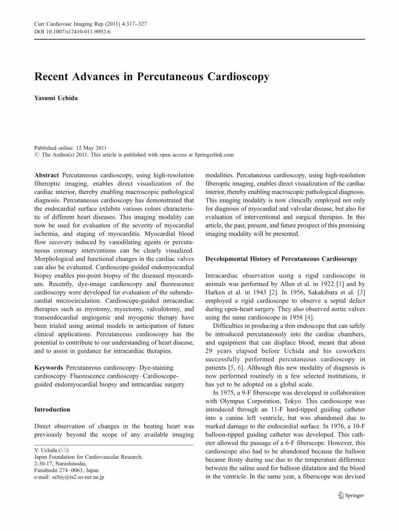
After successful percutaneous coronary interventions,fluorescence appears or its intensity is increased, indicatingrestoration of tissue fluid flow (Fig. 11). However,myocardial tissue flow does not necessarily normalize,indicating that successful epicardial coronary recanalizationdoes not necessarily result in recovery of coronarymicrocirculation.
These results obtained using dye-staining and fluores-cence cardioscopy suggest a need for new modalities fortreatment of coronary microcirculatory disturbances.
Future Directions for Cardioscopy
Cardioscope-Guided Intracardiac Surgery
Cardioscope-guided myotomy, myectomy, and valvulot-omy have been trialed in animals in anticipation of theirclinical application [44–47]. These therapeutic modali-ties will soon be available for application in clinicalsituations.
Cardioscope-Guided Trans-endocardial Angiogenicand Myogenic Therapy
About 15% of patients with ischemic heart disease arenot indicated for surgical or other interventions. Atpresent, no other curative treatments are available forthem.
Myocardial salvage through the formation of new bloodvessels by either angiogenesis or vasculogenesis (angio-genic therapy) is one promising therapeutic modality forthese patients. Cardioscope-guided trans-endocardial angio-genic therapy has been trialed in animals [48]. Using dye-staining and fluorescence cardioscopy, pin-point angiogenicand myogenic therapy can be performed with moreprecision in the clinical situation.
Fig. 11 Fluorescence cardioscopy before and after percutaneouscoronary intervention (PCI). A and E, Conventional cardioscopybefore and after PCI, respectively. The endocardial color changedfrom white to red, indicating restoration of blood flow. B to D, Time-
course changes in fluorescence intensity before PCI. F to H, Time-course changes in fluorescence intensity after PCI. An increase influorescence intensity indicates flow restoration is evident. (FromUchida et al. [43••]; with permission)
Curr Cardiovasc Imaging Rep (2011) 4:317–327 325
Conclusions
Recent advances in cardioscopy technology enable us toobserve the interior of the heart. This imaging technology isnow used for the diagnosis of myocardial and valvulardiseases, evaluation of the severity of myocardial ischemia,interventional and surgical treatments, and for guidance ofendomyocardial biopsy. This technique will be employedfor the guidance of transcatheter interventional and surgicaltreatments of various heart diseases in the near future.
Disclosure No potential conflict of interest relevant to this articlewas reported.
Open Access This article is distributed under the terms of theCreative Commons Attribution Noncommercial License which per-mits any noncommercial use, distribution, and reproduction in anymedium, provided the original author(s) and source are credited.
References
Papers of particular interest, published recently, have beenhighlighted as:• Of importance,•• Of major importance
1. Allen DS, Graham EA. Intracardiac surgery—a new method. AmMed Ass. 1922;79:1028.
2. Harken DE, Glidden EM. Experiments in intracardiac surgery. II.Intracardiac visualization. J Thorac Surg. 1943;12:566.
3. Sakakibara H, Ichikawa T, Hattori J. An intraoperative method forobservation of cardiac septal defect using a cardioscope. Opera-tion. 1956;10:285–90.
4. Sakakibara H, Iijima T, Hattori J, et al. Direct visual operation foraortic stenosis: cardioscope studies. J Int Coll Surg. 1958;29:548–52.
5. Uchida Y, Tomaru T, Nakamura F, et al. Fiberoptic angioscopy ofcardiac chambers, valves and great vessels using a guidingballoon catheter in dog. Am Heart J. 1988;118:1297–302.
6. Uchida Y, Ohshima T, Shibuya I. Percutaneous angioscopy of theright side of the heart in humans. Cardiovasc World Rep.1988;1:13–7.
7. Uchida Y. Clinical application of percutaneous cardioscopy forcoronary heart disease. In: Uchida Y, editor. Coronary angioscopy.NY: Futura; 2001. p. 181–233.
8. Uchida Y. Percutaneous cardiovascular angioscopy. In: Abela G,editor. Lasers in cardiovascular medicine and surgery. Boston:Kluwer Academic Press; 1989. p. 399–410.
9. Uchida Y, Fujimori Y, Hirose J. Percutaneous cardioscopy. JpnHeart J. 1992;33:271–94.
10. Uchida Y. Atlas of cardioangioscopy. Tokyo: Medical View; 1995.p. 94–129.
11. Uchida Y, Nakamura F, Tsukamoto T, et al. Percutaneousventricular endomyocardial biopsy with angioscopic guidance.Am Heart J. 1989;118:1039–41.
12. Uchida Y, Kanai M, Sakura T. Discrimination of left ventricularmyocardial layers by an intracardiac ultrasonography in patientswith ischemic heart disease. Jpn Circulat J. 2000;64(Suppl I):172.
13. Hirose J, Sasaki S, Morizuki M, et al. Follow-up study of patientswith idiopathic myocarditis by percutaneous cardioscopy. Cardi-oangioscopy and Laser Cardioangioplasty. 1995;5:33–4.
14. Aylin Arici M, Kilink E, Demir O, et al. Interactions betweenverapamil an1d digoxin in Langendorff-perfused rat hearts: therole of inhibition of p-glycoprotein in the heart. Basic ClinPharmacol Toxicol. 2010;20:20–30.
15. Uchida Y, Tomaru T, Nakamura F, et al. Percutaneous cardioscopyof the left ventricle in patients with myocarditis. SPIE.1992;1642:214–6.
16. Uchida Y, Sakurai T, Kanai M, et al. Relationships betweencardioscopic images and histological changes in the left ventricleof patients with idiopathic myocarditis. Eur J Heart Failure.2011;13:504–12.
17. Uchida Y, Fujimori Y, Hirose J. Percutaneous left ventricularendomyocardial biopsy with angioscopic guidance in patientswith dilated cardiomyopathy. Am Heart J. 1990;119:949–52.
18. Fujimori Y, Oshima T, Hirose J, et al. Cardioscopic features ofleft ventricle in patients with idiopathic hypertrophic cardio-myopathy. Cardioangioscopy and Laser Cardioangioplasty,1991;4:28.
19. Yilmaz H, Demir I, Uyar Z. Clinical and coronary angiographiccharacteristics of patients with coronary slow flow. Acta Cardiol.2008;63:579–84.
20. Danieles DV, Fearon WF. The index of microcirculatory resistance(IMR) in takotsubo cardiomyopathy. Catheter Cardiovasc Interv.2010;75:77–9.
21. Fizianska A, Walczak E, Glinska Z, et al. Ultrastructural evidenceof myocardial remodeling in peripartum cardiomyopathy. Med SciMonit 2010; 16: CS62-66.
22. Pasqui AL, Pussetti L, Di Renzo M, et al. Structural andfunctional abnormality of systemic microvessels in cardiacsyndrome X. Nutr Metab Cardiovasc Dis. 2005;15:56–64.
23. Mohri M, Koyanagi M, Egarashi K, et al. Angina pectoris causedby coronary microvascular angina. Lancet. 1998;351:1165–9.
24. Uchida Y, Kanai M, Ohsawa H, et al. Direct visualization ofsubendocardial microvessels by percutaneous cardioscopy inpatients with heart disease. Circulation. 1998; 98 (Suppl): I-448.
25. Becker RC. Thrombogenesis in atrial fibrillation contributingmechanisms and natural history. J Thromb Thrombolysis.2009;27:119–1121.
26. Han SW, Nam HS, Kim SH, et al. Frequency and significance ofcardiac sources of embolism in TOAST classification. Cerebro-vasc Dis. 2007;24:463–8.
27. Kaviak ES, Kucukoglu H, Yigit Z, et al. Clinical and echocardio-graphic risk factors for embolization in the presence of left atrialthrombus. Echocardiography. 2007;24:515–21.
28. Bemhardt P, Schmidt H, Hammerstingl C, et al. Atrial thrombi-aprospective follow-up study over 3 years with transesophagealechocardiography and cranial magnetic resonance imaging.Echocardiography. 2006;23:388–94.
29. Siebelink HM, Scholte AJ, Van de Veire NR, et al. Value ofcontrast echocardiography for left ventricular thrombus detectionpost-infarcton and impact on antithrombotic therapy. Coron ArteryDis. 2009;20:462–6.
30. Kane A, Mbaye M, Ndiaye MB, et al. Evolution and thrombo-embolic complications of the idiopathic peripartal cardiomyopathyat Dakar University Hospital: forward-looking study about 33cases. J Gynécol Obstét Biol Reprod. 2010;14:55–60.
31. Choi SH, Jeong SI, Yang JH, et al. A single-center experiencewith Intracardiac thrombosis in children with dilated cardiomy-opathy. Pediatr Cardiol. 2010;31:264–9.
32. Aboukhoudir F, Rekik S, Hirsch JL. Images in cardiovascularmedicine. Live echocardiographic visualization of the migrationof a voluminous left ventricular thrombus complicating an acutemyocarditis. Circulation. 2009;120:e8–10.
326 Curr Cardiovasc Imaging Rep (2011) 4:317–327
33. Sen T, Gungor O, Akpinar I, et al. Cardiac involvement inhypereosinophilic syndrome. Tex Heart Inst J. 2009;36:628–9.
34. Buchibinder NA, Yu R, Rosenbloom BE, et al. Left ventricularthrombus and embolic stroke caused by a functional para-ganglioma. J Clin Hypertens. 2009;11:734–7.
35. Cianciulli TF, Saccheri MC, Lax JA, et al. Left ventricularthrombus mimicking primary cardiac tumor in a patient withprimary antiphospholipid syndrome and recurrent systemic em-bolism. Cardiol J. 2006;16:560–3.
36. Oshima T, Hirose J, Sasaki M, et al. Detection of mural thrombusof cardiac chambers by percutaneous cardioscopy. Cardioangio-scopy and Laser Cardioangioplasty. 1995;5:35–6.
37. Uchida Y, Uchida Y, Sakurai T, et al. Cardioscopic detection ofleft ventricular thrombi. Proceeding of 24th Annual Meeting ofJapanese Association for Cardioangioscopy 2010;10:21.
38. Uchida Y, Ohshima T, Yoshihara F, et al. Percutaneousfiberoptic angioscopy of the cardiac valves. Am Heart J.1991;121:1791–8.
39. Uchida Y, Percutaneous angioscopy of cardiac chambers andvalves. In: Progress in Cardiology, Zipes D, Lea & Febiger (ed),Boston, Philadelphia, 1991; 163–192.
40. Uchida Y. Effects of nitroglycerin and nicorandil on subendocar-dial blood flow in patients with ischemic heart disease. Thera-peutic Research. 1992;3:93–9.
41. Uchida Y, Uchida Y, Shirai S, et al. Heterogeneous arterial andvenous blood filling into the subendocardial myocardium follow-ing nitroglycerin administration in patients with coronary artery
disease. Proceeding of 24th Annual Meeting of JapaneseAssociation for Cardioangioscopy. 2010; 69.
42. • Uchida Y, Uchida Y, Sakurai T, et al. Imaging of subendocardialmyocardial blood flow by dye-staining cardioscopy in patientswith coronary artery disease. Int Heart J. 2010; 51: 308–311.Direct visualization of regional subendocardial myocardial bloodflow was performed using percutaneous dye-staining cardioscopyin patients.
43. •• Uchida Y, Uchida Y, Koga A, et al. Evaluation of myocardialtissue fluid low by fluorescence cardioscopy in patients withcoronary artery disease. Int Heart J 2010; 51: 153–158. Directvisualization of subendocardial tissue fluid flow was performedusing percutaneous fluorescence cardioscopy in patients.
44. Uchida Y, Nakamura F, Kido H, et al. Percutaneous cardiomyot-omy and valvulotomy with angioscopic guidance. Am Heart J.1991;121:1221–4.
45. Nakamura F, Miwa F, Uchida Y, et al. Percutaneous intracardiacsurgery with cardioscopic guidance. SPIE. 1992;1642:217–20.
46. Nakamura F, Uchida Y, Tomaru T, et al. Laser ablation ofmyocardium with angioscopic guidance. 63th Scientific Sessionsof Am Heart Association. Dallas, 1990.
47. Uchida Y, Tomaru T, Nakamura F, et al. Transcatheter treatment ofhypertrophic obstructive cardiomyopathy. Jpn Circulat J 1991;(Suppl):130.
48. Koga A. Selective arteriogenesis induced by transplantation ofbone marrow mononuclear cells with all-trans retinoic acid toischemic myocardium. J Tokyo Jikei Univ. 2004;119:413–9.
Curr Cardiovasc Imaging Rep (2011) 4:317–327 327