Embed Size (px)
Citation preview

J. Europ. Opt. Soc. Rap. Public. 9, 14013 (2014) www.jeos.org
Recent advances in miniaturized optical gyroscopes
F. Dell’Olio Optoelectronics Laboratory, Politecnico di Bari, Via Orabona 4, 70125 Bari, Italy
T. Tatoli Optoelectronics Laboratory, Politecnico di Bari, Via Orabona 4, 70125 Bari, Italy
Optoelectronics Laboratory, Politecnico di Bari, Via Orabona 4, 70125 Bari, Italy
M. N. Armenise Optoelectronics Laboratory, Politecnico di Bari, Via Orabona 4, 70125 Bari, Italy
Low-cost chip-scale optoelectronic gyroscopes having a resolution ≤ 10/h and a good reliability also in harsh environments could havea strong impact on the medium/high performance gyro market, which is currently dominated by well-established bulk optical angularvelocity sensors. The R&D activity aiming at the demonstration of those miniaturized sensors is crucial for aerospace/defense industry,and thus it is attracting an increasing research effort and notably funds.
In this paper the recent technological advances on the compact optoelectronic gyroscopes with low weight and high energy saving arereviewed. Attention is paid to both the so-called gyroscope-on-a-chip, which is a novel sensor, at the infantile stage, whose opticalcomponents are monolithically integrated on a single indium phosphide chip, and to a new ultra-high Q ring resonator for gyro applicationswith a configuration including a 1D photonic crystal in the resonant path. The emerging field of the gyros based on passive ring cavities,which have already shown performance comparable with that of optical fiber gyros, is also discussed.[DOI: http://dx.doi.org/10.2971/jeos.2014.14013]
Keywords: Optoelectronics, integrated optics, optoelectronic sensors, gyroscopes, ring resonators
1 INTRODUCTION
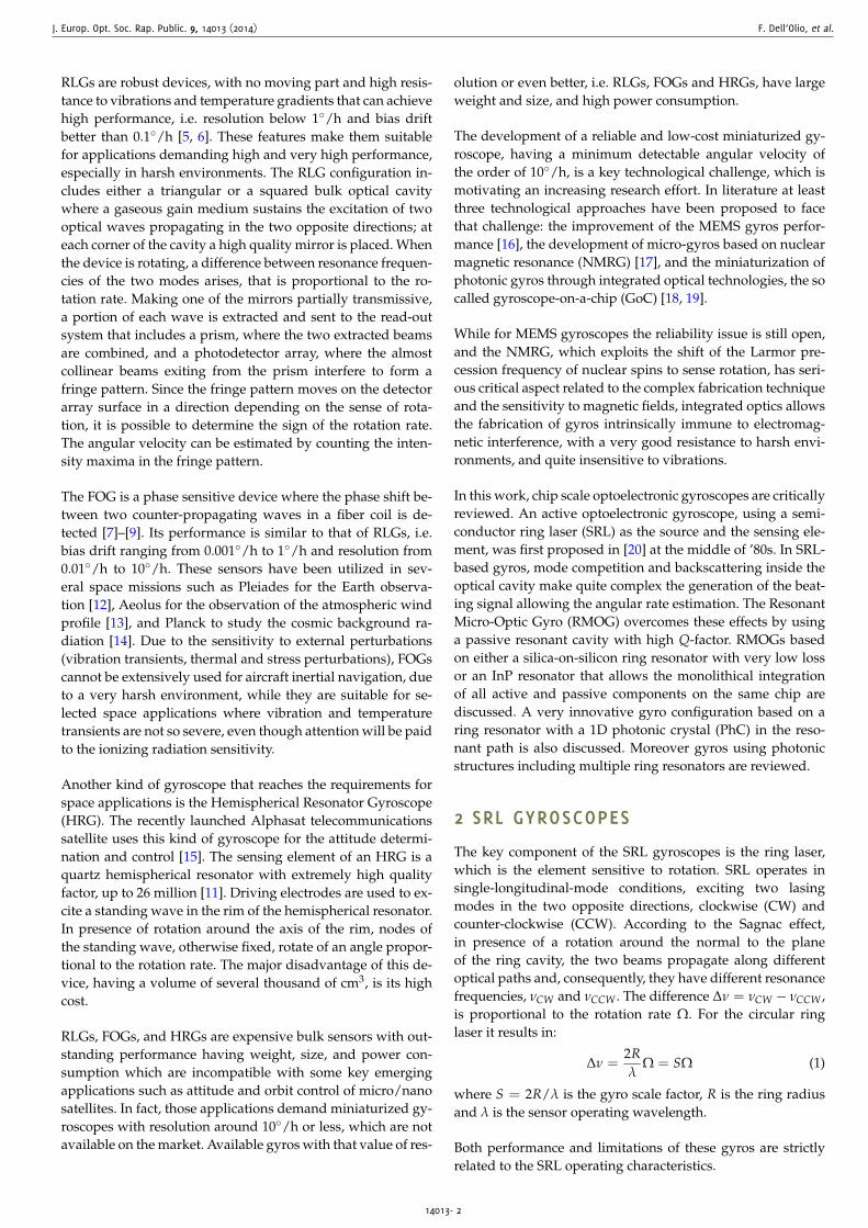
Since several decades, gyroscopes are routinely mounted ona wide range of vehicles such as military and civil airplanes,military ships, submarines, satellites, space launchers, andlong-range ballistic missiles. All those applications, which arein the field of aerospace and defense, demand angular veloc-ity sensors with a resolution ≤ 10/h and a bias drift < 1/h.For example, attitude and orbit control of satellites for Earthobservation/scientific mission and inertial navigation of sub-marines impose very stringent requirements in terms of biasdrift and resolution, respectively of the order of 0.01/h and0.1/h, while for applications such as autonomous naviga-tion of rover vehicles and inertial navigation of missiles thereare more relaxed requirements, i.e. bias drift in the rangefrom 0.1/h to 1/h and resolution in the range from 1/hto 10/h [1, 2].
More recently other gyro application areas have emerged, i.e.robotics, medical instruments, automotive, and consumer ap-plications. MEMS technology dominates those new marketsassuring small device size, weight and fabrication cost [3]. Al-though continuous growth in the MEMS gyroscope market isexpected along with their performance enhancement, reliabil-ity still remain a critical issue.
The application domains of angular velocity sensors with the
FIG. 1 Applications and requirements for different gyroscope technologies.
required performance and the available gyro technologies aresummarized in Figure 1.
Almost half of the high-performance gyroscope market iscovered by defense applications, while commercial aerospacerepresents the 25% of the market [4]. Currently these twomarket sectors are dominated by two well-established opto-electronic angular velocity sensor technologies, i.e. the op-tical technology, with Ring Laser Gyroscopes (RLGs) [5, 6]and Fiber Optic Gyroscopes (FOGs) [7]–[9], both based onthe Sagnac effect [10], and the Hemispherical Resonator Gy-roscopes (HRGs) [3, 11] based on the Coriolis force.
Received November 29, 2013; revised ms. received February 13, 2014; published March 11, 2014 ISSN 1990-2573
J. Europ. Opt. Soc. Rap. Public. 9, 14013 (2014) F. Dell’Olio, et al.
RLGs are robust devices, with no moving part and high resis-tance to vibrations and temperature gradients that can achievehigh performance, i.e. resolution below 1/h and bias driftbetter than 0.1/h [5, 6]. These features make them suitablefor applications demanding high and very high performance,especially in harsh environments. The RLG configuration in-cludes either a triangular or a squared bulk optical cavitywhere a gaseous gain medium sustains the excitation of twooptical waves propagating in the two opposite directions; ateach corner of the cavity a high quality mirror is placed. Whenthe device is rotating, a difference between resonance frequen-cies of the two modes arises, that is proportional to the ro-tation rate. Making one of the mirrors partially transmissive,a portion of each wave is extracted and sent to the read-outsystem that includes a prism, where the two extracted beamsare combined, and a photodetector array, where the almostcollinear beams exiting from the prism interfere to form afringe pattern. Since the fringe pattern moves on the detectorarray surface in a direction depending on the sense of rota-tion, it is possible to determine the sign of the rotation rate.The angular velocity can be estimated by counting the inten-sity maxima in the fringe pattern.
The FOG is a phase sensitive device where the phase shift be-tween two counter-propagating waves in a fiber coil is de-tected [7]–[9]. Its performance is similar to that of RLGs, i.e.bias drift ranging from 0.001/h to 1/h and resolution from0.01/h to 10/h. These sensors have been utilized in sev-eral space missions such as Pleiades for the Earth observa-tion [12], Aeolus for the observation of the atmospheric windprofile [13], and Planck to study the cosmic background ra-diation [14]. Due to the sensitivity to external perturbations(vibration transients, thermal and stress perturbations), FOGscannot be extensively used for aircraft inertial navigation, dueto a very harsh environment, while they are suitable for se-lected space applications where vibration and temperaturetransients are not so severe, even though attention will be paidto the ionizing radiation sensitivity.
Another kind of gyroscope that reaches the requirements forspace applications is the Hemispherical Resonator Gyroscope(HRG). The recently launched Alphasat telecommunicationssatellite uses this kind of gyroscope for the attitude determi-nation and control [15]. The sensing element of an HRG is aquartz hemispherical resonator with extremely high qualityfactor, up to 26 million [11]. Driving electrodes are used to ex-cite a standing wave in the rim of the hemispherical resonator.In presence of rotation around the axis of the rim, nodes ofthe standing wave, otherwise fixed, rotate of an angle propor-tional to the rotation rate. The major disadvantage of this de-vice, having a volume of several thousand of cm3, is its highcost.
RLGs, FOGs, and HRGs are expensive bulk sensors with out-standing performance having weight, size, and power con-sumption which are incompatible with some key emergingapplications such as attitude and orbit control of micro/nanosatellites. In fact, those applications demand miniaturized gy-roscopes with resolution around 10/h or less, which are notavailable on the market. Available gyros with that value of res-
olution or even better, i.e. RLGs, FOGs and HRGs, have largeweight and size, and high power consumption.
The development of a reliable and low-cost miniaturized gy-roscope, having a minimum detectable angular velocity ofthe order of 10/h, is a key technological challenge, which ismotivating an increasing research effort. In literature at leastthree technological approaches have been proposed to facethat challenge: the improvement of the MEMS gyros perfor-mance [16], the development of micro-gyros based on nuclearmagnetic resonance (NMRG) [17], and the miniaturization ofphotonic gyros through integrated optical technologies, the socalled gyroscope-on-a-chip (GoC) [18, 19].
While for MEMS gyroscopes the reliability issue is still open,and the NMRG, which exploits the shift of the Larmor pre-cession frequency of nuclear spins to sense rotation, has seri-ous critical aspect related to the complex fabrication techniqueand the sensitivity to magnetic fields, integrated optics allowsthe fabrication of gyros intrinsically immune to electromag-netic interference, with a very good resistance to harsh envi-ronments, and quite insensitive to vibrations.
In this work, chip scale optoelectronic gyroscopes are criticallyreviewed. An active optoelectronic gyroscope, using a semi-conductor ring laser (SRL) as the source and the sensing ele-ment, was first proposed in [20] at the middle of ’80s. In SRL-based gyros, mode competition and backscattering inside theoptical cavity make quite complex the generation of the beat-ing signal allowing the angular rate estimation. The ResonantMicro-Optic Gyro (RMOG) overcomes these effects by usinga passive resonant cavity with high Q-factor. RMOGs basedon either a silica-on-silicon ring resonator with very low lossor an InP resonator that allows the monolithical integrationof all active and passive components on the same chip arediscussed. A very innovative gyro configuration based on aring resonator with a 1D photonic crystal (PhC) in the reso-nant path is also discussed. Moreover gyros using photonicstructures including multiple ring resonators are reviewed.
2 SRL GYROSCOPES
The key component of the SRL gyroscopes is the ring laser,which is the element sensitive to rotation. SRL operates insingle-longitudinal-mode conditions, exciting two lasingmodes in the two opposite directions, clockwise (CW) andcounter-clockwise (CCW). According to the Sagnac effect,in presence of a rotation around the normal to the planeof the ring cavity, the two beams propagate along differentoptical paths and, consequently, they have different resonancefrequencies, νCW and νCCW . The difference ∆ν = νCW − νCCW ,is proportional to the rotation rate Ω. For the circular ringlaser it results in:
∆ν =2Rλ
Ω = SΩ (1)
where S = 2R/λ is the gyro scale factor, R is the ring radiusand λ is the sensor operating wavelength.
Both performance and limitations of these gyros are strictlyrelated to the SRL operating characteristics.
14013- 2
J. Europ. Opt. Soc. Rap. Public. 9, 14013 (2014) F. Dell’Olio, et al.
In a SRL the positive feedback is provided by a closed cavitythat could have different shapes: circular, racetrack, squared,or triangular. In the design of both circular and racetrack SRLsattention must be paid to bending loss that increases when thecurvature radius decreases. Conversely, squared and triangu-lar SRLs, can provide lower loss [21].
Electrically pumped SRLs are fabricated in III-V semiconduc-tors and their basic structure includes a substrate and a pnjunction that encloses the active region. Usually the active re-gion is formed by a graded-index separate confinement het-erostructure in which there are single or multiple quantumwell separated by barriers of graded-index. The advantage ofthis configuration is the possibility to separate the optical andthe electrical confinements.
In the evolution of the SRL, attention was paid to the ap-proach used to partially extract the beams generated withinthe laser cavity. In fact, the coupling mechanism affects thelaser behavior, causing back-reflection in the cavity, so defin-ing the portion of the light extracted from the cavity. The us-able coupling techniques are: Y-junction, multimode interfer-ence (MMI) coupler and evanescent coupler. The first one hasvery strong intracavity back-reflection, while this is negligiblein the case of the evanescent coupler, even if this latter requiresa very accurate fabrication process because of the very smallgap between the resonator and the waveguide. For the MMIcoupler the fabrication tolerance is not so stringent and intra-cavity back-reflection is weak [22, 23].
In [24] the fabrication and the optical characterization of anSRL with a double quantum well GaAs/AlGaAs structureweakly coupled to a straight waveguide, is reported. Thethreshold current measured for this laser, having a radius of1 mm, is 195 mA. At high injection current nonlinear effectsarise due to self-saturation and cross-saturation effects in thegain medium, which, together with the mode competition ef-fect and the lock-in effect, degrade the performance of the de-vice.
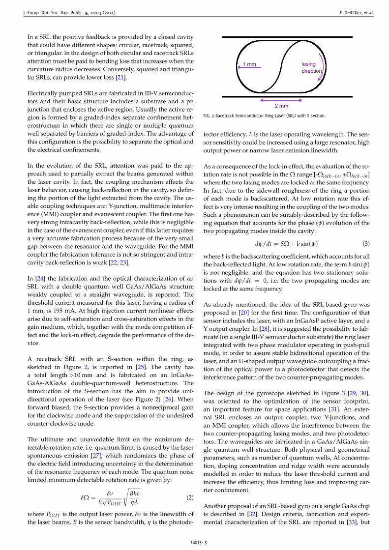
A racetrack SRL with an S-section within the ring, assketched in Figure 2, is reported in [25]. The cavity hasa total length >10 mm and is fabricated on an InGaAs-GaAs-AlGaAs double-quantum-well heterostructure. Theintroduction of the S-section has the aim to provide uni-directional operation of the laser (see Figure 2) [26]. Whenforward biased, the S-section provides a nonreciprocal gainfor the clockwise mode and the suppression of the undesiredcounter-clockwise mode.
The ultimate and unavoidable limit on the minimum de-tectable rotation rate, i.e. quantum limit, is caused by the laserspontaneous emission [27], which randomizes the phase ofthe electric field introducing uncertainty in the determinationof the resonance frequency of each mode. The quantum noiselimited minimum detectable rotation rate is given by:
δΩ =δν
S√
POUT
√Bhcηλ
(2)
where POUT is the output laser power, δν is the linewidth ofthe laser beams, B is the sensor bandwidth, η is the photode-
1 mm lasingdirection
2 mm
FIG. 2 Racetrack Semiconductor Ring Laser (SRL) with S section.
tector efficiency, λ is the laser operating wavelength. The sen-sor sensitivity could be increased using a large resonator, highoutput power or narrow laser emission linewidth.
As a consequence of the lock-in effect, the evaluation of the ro-tation rate is not possible in the Ω range [-Ωlock−in, +Ωlock−in]where the two lasing modes are locked at the same frequency.In fact, due to the sidewall roughness of the ring a portionof each mode is backscattered. At low rotation rate this ef-fect is very intense resulting in the coupling of the two modes.Such a phenomenon can be suitably described by the follow-ing equation that accounts for the phase (ψ) evolution of thetwo propagating modes inside the cavity:
dψ/dt = SΩ + b sin(ψ) (3)
where b is the backscattering coefficient, which accounts for allthe back-reflected light. At low rotation rate, the term b sin(ψ)is not negligible, and the equation has two stationary solu-tions with dψ/dt = 0, i.e. the two propagating modes arelocked at the same frequency.
As already mentioned, the idea of the SRL-based gyro wasproposed in [20] for the first time. The configuration of thatsensor includes the laser, with an InGaAsP active layer, and aY output coupler. In [28], it is suggested the possibility to fab-ricate (on a single III-V semiconductor substrate) the ring laserintegrated with two phase modulator operating in push-pullmode, in order to assure stable bidirectional operation of thelaser, and an U-shaped output waveguide outcoupling a frac-tion of the optical power to a photodetector that detects theinterference pattern of the two counter-propagating modes.
The design of the gyroscope sketched in Figure 3 [29, 30],was oriented to the optimization of the sensor footprint,an important feature for space applications [31]. An exter-nal SRL encloses an output coupler, two Y-junctions, andan MMI coupler, which allows the interference between thetwo counter-propagating lasing modes, and two photodetec-tors. The waveguides are fabricated in a GaAs/AlGaAs sin-gle quantum well structure. Both physical and geometricalparameters, such as number of quantum wells, Al concentra-tion, doping concentration and ridge width were accuratelymodelled in order to reduce the laser threshold current andincrease the efficiency, thus limiting loss and improving car-rier confinement.
Another proposal of an SRL-based gyro on a single GaAs chipis described in [32]. Design criteria, fabrication and experi-mental characterization of the SRL are reported in [33], but
14013- 3
J. Europ. Opt. Soc. Rap. Public. 9, 14013 (2014) F. Dell’Olio, et al.
PDSRL
curved waveguide
MMI coupler
FIG. 3 Compact configuration of an SRL based gyro [29, 30] that includes an SRL inside
of which there are a curved waveguide, an MMI coupler and two photodetectors for
the system read-out.
no beating frequency was measured from the device rotationtreated up to 109/h [34].
The sensor proposed in [35] has the objective to simplify thegyro, detecting the Sagnac frequency difference directly fromthe voltage signal across the laser electrodes, thus avoidingthe need of additional read-out components. To confirm thispossibility, experiments have been conducted on a SRL gyrowhose ring resonator is a fiber loop using a semiconductoroptical amplifier (SOA). The minimum detected rotation ratereported is equal to ∼2×10³/h. Thus a proof of the directproportionality between the applied mechanical rotation andthe voltage across the SOA terminals was given. A theoreticalanalysis on the physical behavior of that device based on rateequations has been developed in [36].
The patented miniaturized integrated optical gyroscopein [37] has a footprint of 3 mm × 5 mm, including a doublequantum well ring laser, a circular directional coupler, anelectro-optic phase modulator, an Y-junction and a photode-tector (see Figure 4). The two beams, allowing the angularvelocity estimation, are generated by the ring laser, extractedby the coupler and interfere in the Y-junction, where the beat-ing signal is generated. The electro-optic phase modulatoroperates in push-pull configuration adding a constant phaseshift of π/2 to the two counter-propagating laser beams.This phase shift allows the detection of the sign of rotation.The choice of the material substrate (GaAs) is oriented to thereduction of the emission wavelength and the consequentscale factor improvement. The calculated shot noise limitedresolution of that sensor is 0.01/h.
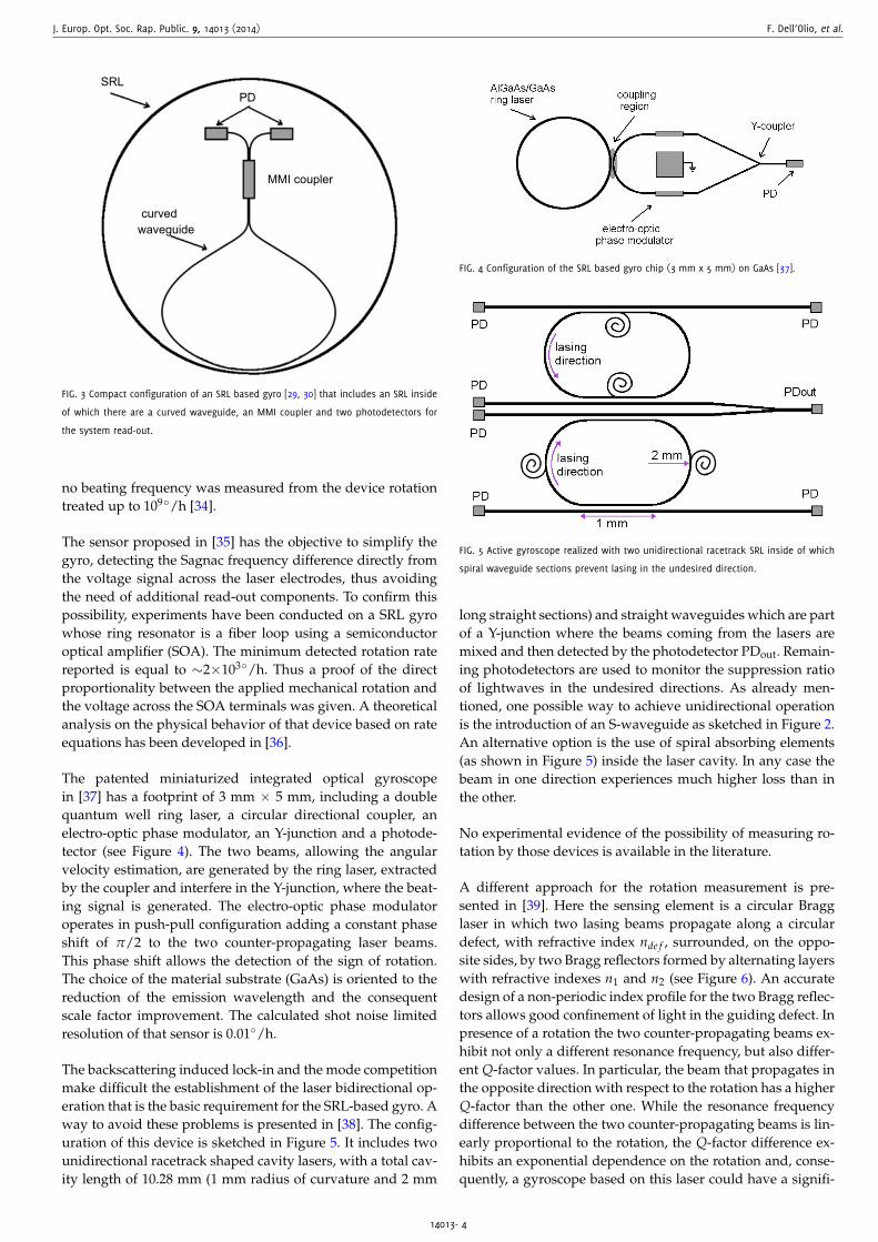
The backscattering induced lock-in and the mode competitionmake difficult the establishment of the laser bidirectional op-eration that is the basic requirement for the SRL-based gyro. Away to avoid these problems is presented in [38]. The config-uration of this device is sketched in Figure 5. It includes twounidirectional racetrack shaped cavity lasers, with a total cav-ity length of 10.28 mm (1 mm radius of curvature and 2 mm
PD
FIG. 4 Configuration of the SRL based gyro chip (3 mm x 5 mm) on GaAs [37].
FIG. 5 Active gyroscope realized with two unidirectional racetrack SRL inside of which
spiral waveguide sections prevent lasing in the undesired direction.
long straight sections) and straight waveguides which are partof a Y-junction where the beams coming from the lasers aremixed and then detected by the photodetector PDout. Remain-ing photodetectors are used to monitor the suppression ratioof lightwaves in the undesired directions. As already men-tioned, one possible way to achieve unidirectional operationis the introduction of an S-waveguide as sketched in Figure 2.An alternative option is the use of spiral absorbing elements(as shown in Figure 5) inside the laser cavity. In any case thebeam in one direction experiences much higher loss than inthe other.
No experimental evidence of the possibility of measuring ro-tation by those devices is available in the literature.
A different approach for the rotation measurement is pre-sented in [39]. Here the sensing element is a circular Bragglaser in which two lasing beams propagate along a circulardefect, with refractive index nde f , surrounded, on the oppo-site sides, by two Bragg reflectors formed by alternating layerswith refractive indexes n1 and n2 (see Figure 6). An accuratedesign of a non-periodic index profile for the two Bragg reflec-tors allows good confinement of light in the guiding defect. Inpresence of a rotation the two counter-propagating beams ex-hibit not only a different resonance frequency, but also differ-ent Q-factor values. In particular, the beam that propagates inthe opposite direction with respect to the rotation has a higherQ-factor than the other one. While the resonance frequencydifference between the two counter-propagating beams is lin-early proportional to the rotation, the Q-factor difference ex-hibits an exponential dependence on the rotation and, conse-quently, a gyroscope based on this laser could have a signifi-
14013- 4
J. Europ. Opt. Soc. Rap. Public. 9, 14013 (2014) F. Dell’Olio, et al.
FIG. 6 Circular Bragg laser with a circular guiding defect, having refractive index ndef,
surrounded by two Bragg reflectors in which dark rings have refractive index n1 and
white rings n2 < n1 [39].
cantly enhanced performance. To our knowledge, that conceptwas never experimentally demonstrated.
In the last few years, the research effort on the SRL-based gyrowas quickly decreasing due to some critical aspects of that de-vice. We believe that only the identification of effective coun-termeasures mitigating lock-in and mode competition couldallow the demonstration of the first prototype.
3 RESONANT MICRO OPTICALGYROSCOPES (RMOGS)
Critical effects in SRL gyroscopes, i.e. backscattering, lock-ineffect and mode competition, are intrinsically related to theSRL operation features. Therefore, they can be overcome bydecoupling the laser source and the sensing element, as in theResonant Micro-optic Gyroscope (RMOG), in which a passivering resonator operates as the sensing element and an externallaser source is used.
The configuration of an RMOG includes a narrow linewidthlaser source, a high Q ring resonator, an optoelectronic pro-cessing unit, two photodetectors and an electronic read-outunit (see Figure 7). This sensor can be manufactured by usingdifferent technologies for each component: hybrid or mono-lithic integration. In the hybrid integration, it is possible tochoose, for each component, the technology that assures thebest performance, but the alignment of all components is dif-ficult and the loss is larger. Monolithically integrated gyro-scopes are surely more robust, compact and less power con-suming.
In the RMOG, the rotation rate is measured by the differ-ence between the resonance frequencies of the two counter-propagating beams injected into the high Q ring resonator.The ultimate limit on the measurement of the rotation rate isset by the shot noise at the photodetectors and is given by [40]:
δΩ =1
Qd√
PPD
√2hc3
λ0ητint(4)
where d is the diameter of the ring resonator, Q its qualityfactor, λ0 is the sensor operating wavelength, τint is the sensorintegration time, PPD is the power at the photodetector, η is
FIG. 7 Configuration of a Resonant Micro-Optic Gyroscope (RMOG), including a laser,
a Beam Splitter (BS), Opto-Electronic (OE) components for signal processing, a ring
resonator, two detectors (D) and an electronic read-out unit.
the photodetector efficiency, h is the Planck constant, and c isthe velocity of light in vacuum.
In addition to the unavoidable shot noise limit, RMOGs crit-ical issues are the polarization fluctuations of the two modespropagating in the resonator, the backscattering effect, and theKerr effect.
The key element of the system in Figure 7 is the ring res-onator that strongly influences the gyro sensitivity. Currentlyring resonators are considered fundamental building blocksfor very large scale of integration (VLSI) photonics and a lot ofcomponents based on them, such as filters, wavelength divi-sion multiplexing systems, logic ports, modulators and lasers,have been demonstrated.
Different material systems are used for the fabrication of ringcavities. Silica-on-silicon and silicon nitride technologies al-low the fabrication of resonators with very low loss [41]–[43],but LiNbO3 [44], glass [45, 46], silicon [47], polymers [48], andInP [49, 50] are also used. Along with these fully passive ringresonators, some configurations, including an optical ampli-fier to compensate losses, have been also proposed and exper-imented [51, 52].
Gyroscope resolution can be enhanced through the use ofring resonators with very high Q-factors (see Eq. (4)). HighQ values can be achieved by reducing ring resonator loss,mainly propagation loss and scattering loss due to roughnessin waveguide sidewalls. To our knowledge, the best perform-ing planar ring resonators are those ones reported in [41], fab-ricated in silica-on-silicon technology, and in [42, 43], fabri-cated in silicon nitride. In [41], measured propagation loss ofa phosphorous doped silica-on-silicon ring resonator havinga diameter of 6 cm, is equal to 0.0085 dB/cm and the resultingQ-factor is equal to 2.3×10⁷. More recently high-Q Si3N4 ringresonators on silicon substrate have been reported. In [43],for a ring resonator with 7 µm core width, 45 nm core thick-ness, and 9.8 mm ring radius, a loaded Q-factor of 3.5×10⁷
at 1550 nm has been measured, and the intrinsic Q-factor re-sulted to be 5.5×10⁷.
Moreover, also microtoroids and wedge resonators have
14013- 5
J. Europ. Opt. Soc. Rap. Public. 9, 14013 (2014) F. Dell’Olio, et al.
demonstrated very high Q-factor. In particular, for the wedgeresonator in [53], having a diameter of 7.5 mm, an ultra-highQ-factor equal to 8.75×10⁸ has been experimentally demon-strated. The monolithic integration of this kind of resonantcavities with an input/output waveguide is a critical issue.In [54] a technique allowing the fabrication of a microtoroidand a bus straight waveguide monolithically integrated ona silicon chip is reported. With the proposed fabricationprocess, a microtoroid resonator, having a diameter equal to70 µm, monolithically integrated with a bus waveguide hasbeen demonstrated to have Q = 3.2×10⁶ at 1550 nm, and aQ value in excess of 4 million at 1330 nm. However, becauseof the complexity of the integration with other components,these structures cannot be considered as sensing element ofthe RMOGs.
3.1 RMOGs based on ultra-high Qsi l ica-on-si l icon ring resonator
RMOGs based on silica-on-silicon ring resonators have beenextensively studied [55]–[58] and some prototypes [59] havebeen demonstrated. The main advantage of this technology isthe very low waveguide propagation loss achievable, downto 0.01 dB/cm [41], which allows the fabrication of large ringresonators with Q-factor as high as 107 that is beneficial forthe gyroscope resolution. For example an RMOG using thering resonator investigated in [41], which has Q = 2.3×10⁷,would have a theoretical estimated shot noise limited resolu-tion equal to 0.2/h (with PPD = 1 mW; η = 0.9; τint = 10 s).
The possibility of using a silica-on-silicon resonator, as thesensing element in a passive optical gyro, was first demon-strated in [60], where the operation of an RMOG using a 5 cmdiameter resonator, having a finesse of 10, was designed andexperimentally investigated. The resolution was of the orderof 106/h. Without the implementation of suitable counter-measures for fundamental noise sources, i.e. polarization fluc-tuations [61] and backscattering [62], which affect the rotationrate value adding an error that is higher than the shot noise,a good resolution in an adequate integration time cannot beachieved.
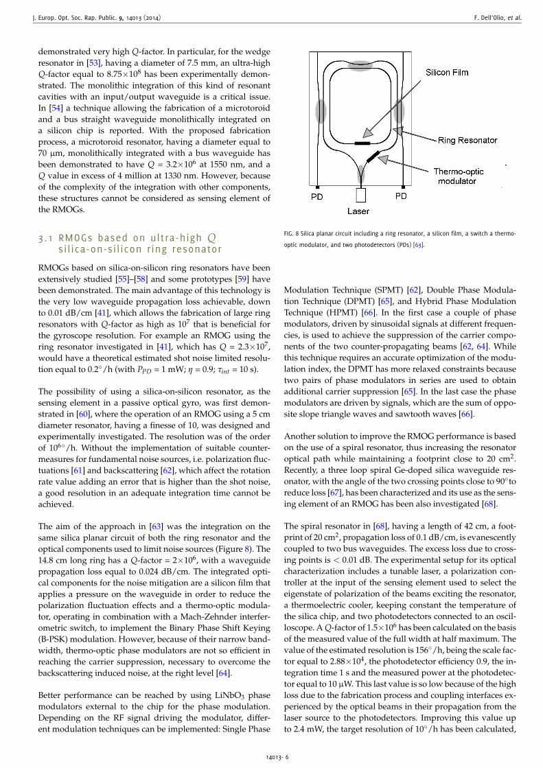
The aim of the approach in [63] was the integration on thesame silica planar circuit of both the ring resonator and theoptical components used to limit noise sources (Figure 8). The14.8 cm long ring has a Q-factor = 2×10⁶, with a waveguidepropagation loss equal to 0.024 dB/cm. The integrated opti-cal components for the noise mitigation are a silicon film thatapplies a pressure on the waveguide in order to reduce thepolarization fluctuation effects and a thermo-optic modula-tor, operating in combination with a Mach-Zehnder interfer-ometric switch, to implement the Binary Phase Shift Keying(B-PSK) modulation. However, because of their narrow band-width, thermo-optic phase modulators are not so efficient inreaching the carrier suppression, necessary to overcome thebackscattering induced noise, at the right level [64].
Better performance can be reached by using LiNbO3 phasemodulators external to the chip for the phase modulation.Depending on the RF signal driving the modulator, differ-ent modulation techniques can be implemented: Single Phase
FIG. 8 Silica planar circuit including a ring resonator, a silicon film, a switch a thermo-
optic modulator, and two photodetectors (PDs) [63].
Modulation Technique (SPMT) [62], Double Phase Modula-tion Technique (DPMT) [65], and Hybrid Phase ModulationTechnique (HPMT) [66]. In the first case a couple of phasemodulators, driven by sinusoidal signals at different frequen-cies, is used to achieve the suppression of the carrier compo-nents of the two counter-propagating beams [62, 64]. Whilethis technique requires an accurate optimization of the modu-lation index, the DPMT has more relaxed constraints becausetwo pairs of phase modulators in series are used to obtainadditional carrier suppression [65]. In the last case the phasemodulators are driven by signals, which are the sum of oppo-site slope triangle waves and sawtooth waves [66].
Another solution to improve the RMOG performance is basedon the use of a spiral resonator, thus increasing the resonatoroptical path while maintaining a footprint close to 20 cm2.Recently, a three loop spiral Ge-doped silica waveguide res-onator, with the angle of the two crossing points close to 90toreduce loss [67], has been characterized and its use as the sens-ing element of an RMOG has been also investigated [68].
The spiral resonator in [68], having a length of 42 cm, a foot-print of 20 cm2, propagation loss of 0.1 dB/cm, is evanescentlycoupled to two bus waveguides. The excess loss due to cross-ing points is < 0.01 dB. The experimental setup for its opticalcharacterization includes a tunable laser, a polarization con-troller at the input of the sensing element used to select theeigenstate of polarization of the beams exciting the resonator,a thermoelectric cooler, keeping constant the temperature ofthe silica chip, and two photodetectors connected to an oscil-loscope. A Q-factor of 1.5×10⁶ has been calculated on the basisof the measured value of the full width at half maximum. Thevalue of the estimated resolution is 156/h, being the scale fac-tor equal to 2.88×10⁴, the photodetector efficiency 0.9, the in-tegration time 1 s and the measured power at the photodetec-tor equal to 10 µW. This last value is so low because of the highloss due to the fabrication process and coupling interfaces ex-perienced by the optical beams in their propagation from thelaser source to the photodetectors. Improving this value upto 2.4 mW, the target resolution of 10/h has been calculated,
14013- 6

J. Europ. Opt. Soc. Rap. Public. 9, 14013 (2014) F. Dell’Olio, et al.
FIG. 9 Configuration of the ring resonator with a 1D PhC included in the resonant path.
while maintaining the same footprint. The estimated bias driftof that sensor is equal to 0.2/h.
In order to maximize the Q-factor of the RMOG sensing ele-ment, resonators with loss compensation have also been in-vestigated, as already mentioned. In the configuration pro-posed in [51], two SOAs are hybridly integrated, in symmet-rical positions within the resonator, in order to fully compen-sate propagation loss. A Q-factor of 2.9×10⁸ and a minimumdetectable rotation rate of 0.2/h can be predicted for the res-onator having a length equal to 94.8 mm. Critical issues of thisconfiguration arise from nonlinear effects that make complexits control. Another type of compensated resonator is inves-tigated in [52]. The proposed racetrack cavity is fabricatedby using an active waveguide in neodymium doped glass.A Q-factor of 1.9×10⁷ is reached for the resonator having alength of 56 mm.
An alternative RMOG configuration is proposed in [69]. Thatsensor is based on two ring resonators that are fabricated in-dependently and then bonded back-to-back into one chip. Theaim of this approach is the reduction of the backscattering,Kerr effect and the polarization fluctuation induced noise.Since only one beam propagates in each resonator, there isnot interference between backscattered light and propagatingbeam. The performance of that device is not mentioned by theauthors.
A very innovative approach for the enhancement of theQ-factor in ring resonators for gyro applications, is describedin [70], where a 1D PhC is included in the resonant path of acircular ring cavity. A possible realization of that idea is a ringresonator in silica-on-silicon technology having a diameterof 4.59 cm, weakly coupled to a straight bus waveguide(coupling efficiency about 2%). The resonant path includesa low-index-contrast Bragg grating extending over all itslength that could be fabricated by an appropriate UV writingtechnique (see Figure 9). Assuming that the guiding structurehas a propagation loss of 0.07 dB/cm, a Q-factor of about7×109 has been calculated for that resonant device.
Basic features of the RMOGs based on silica-on-silicon res-onators with the best shot noise limited resolution are sum-marized in Table 1. The gyro with the best experimentally
measured performance is reported in [65, 71]. The configura-tion of this RMOG includes a fiber laser, whose frequency islocked to the resonance frequency of the CW resonant mode,two couples of phase modulators implementing double phasemodulation technique, the sensing element and other opto-electronic components. The sensing element is a polarizationmaintaining silica waveguide ring resonator having a diame-ter of 2.5 cm and a Q-factor of 3×10⁶. The double phase modu-lation scheme has allowed the reduction of the short term biasstability down to 38/h, for an observation time of 60 s andan integration time of 10 s. The minimum detectable rotationrate was about 400/h [65]. With the same device a long termbias stability of 800/h for 1 h observation time is obtained.
At this stage of their development, RMOGs based on silica-on-silicon cavities exhibit performance which is still far fromthat are demanded by aerospace and defence industry. Theycould be used in automotive and consumer electronics wherethe low-cost MEMS gyros already dominate. Therefore onlyafter the enhancement of their performance of one/two or-der of magnitude, those RMOGs could have a role in the gyromarket. We believe that RMOGs based on a cavity including aBragg grating in the resonant path will have a disruptive im-pact on the market if their performance will be experimentallyconfirmed.
3.2 InP based gyro on a chip
While giving the opportunity to make the best technologicalchoice for each component of RMOGs, the hybrid integrationimposes tight requirements on the alignment of number ofopto-electronic components. The alternative technological so-lution, i.e. the monolithic integration of all gyro optoelectroniccomponents on the same substrate, can provide higher com-pactness of the device and improved immunity to externaldisturbances. The III-V semiconductor technology is the onlyone that could allow the fabrication of a GoC, which includesall active and passive components on the same substrate thusenhancing the scaling of the optical resonant gyroscopes.
The key element of the fully integrated RMOG remains thering resonator, whose size and performance determine thegyro resolution: the product between the resonator Q-factorand its diameter is inversely proportional to the minimum de-tectable rotation rate (see Eq. (4)). As described in [49], a ringresonator with Q ≥ 106 and d ≥ 10 mm is necessary to achievea resolution of δΩ = 10/h or less.
Although ring resonators have been demonstrated bothin In1−xGaxAsyP1−y/InP and in GaAs/AlxGa1−xAs sys-tem, the research effort has been focused on the InP basedmaterial since it exhibits lower loss. However, since inIn1−xGaxAsyP1−y/InP waveguides propagation loss is typi-cally higher than 1 dB/cm, which does not allow to achieve arequired Q value ≥ 106, the optimization of the waveguidedesign and improvement of the technological process stillremains an important goal.
The design, fabrication and characterization of a ring res-onator with radius of 13 mm, coupled to a single bus waveg-uide and fabricated with low loss InGaAsP/InP rib waveg-
14013- 7

J. Europ. Opt. Soc. Rap. Public. 9, 14013 (2014) F. Dell’Olio, et al.
Authors
MeasuredShort term
bias stability(τint = 10 s)
MeasuredResonator Resonator long term Theoretically Shot noise Measuredfootprint Q-factor bias stability estimated limited resolution
(observation bias stability resolution (*)time 1 h)
(cm2) (/h) (/h) (/h) (/h) (/h)Ma et al.,
6.25 3×10⁶ 40 800 - 5 400Mao et al.[65, 71]
Feng et al.,16 7×10⁶ 800 1800 - 1 -Lei et al.
[66, 72]Ciminelli
20 1.5×10⁶ - - 0.2 5 -et al. [68]Ciminelli
21 7×10⁹ - - - < 0.01 -et al. [70]
* Theoretical value with PPD = 1 mW; η = 0.9; τint =10 s.TABLE 1 Basic feature of the best performing RMOGs based on silica-on-silicon ring resonators.
FIG. 10 Spectral response of the ring resonator having radius 13 mm, coupled to a
single bus waveguide from which is separated by a 1524 nm gap; this resonator has a
quality factor of 0.97×10⁶. Reprinted from Ref. [50] with permission of OSA 2013.
uide are reported in [73, 50]. For the realized rib waveguide,with an etch depth of 0.3 µm and a width of 2 µm, a propa-gation loss for the fundamental quasi-TE mode reaching therecord value of 0.45 dB/cm has been measured.
Using an experimental setup that includes a tunable laser anda photodetector connected to an oscilloscope, the resonatorspectral response has been measured (see Figure 10). The res-onator has a quality factor equal to 0.97×10⁶ [50]. If it is usedas the sensing element of an RMOG, the target resolution of10/h can be reached with an average power at photodiodesinput equal to 13.84 mW. In addition to the increase of thepower at photodiodes, in order to obtain better performance, afurther decrease of the propagation loss is required or a largerresonator must be used. Unfortunately, this last choice impliesan increase of the chip footprint with negative consequence onthe uniformity of the technological process.
We believe that the GoC concept is very promising and at-tractive, although its experimental demonstration demandsan additional notably technological effort.
3.3 RMOGs read-out
The RMOGs read-out system has a crucial role in RMOGs,being the frequency difference between the two counter-propagating resonant modes (∆ν = νCW − νCCW), from whichthe measure of the rotation rate is extracted, very little, of theorder of 1 Hz. Moreover, an efficient signal processing tech-nique must be implemented in order to distinguish the rota-tion induced ∆ν from the noise sources, such as backscatteringinduced noise [62, 64, 65], laser frequency noise [74], and fluc-tuations of the resonance frequency of the resonator mainlydue to the temperature drift [75].
Among several configurations proposed for the read-out, ba-sically two options are possible, i.e. phase or frequency modu-lation of the optical signals exciting the ring resonator. Due toits simplicity, the first technique is the most common. In bothcases the read-out circuit can be designed in either open orclosed loop configuration.
The configuration of the read-out system using phase mod-ulation technique is depicted in Figure 11. The signal fromthe laser source is split by the beam splitter (BS). Before en-tering the resonator cavity, the two beams are phase modu-lated by the two phase modulators PM1 and PM2 and fre-quency shifted by the acousto-optic frequency shifters AOM1and AOM2. At this point the amplitude of the two beams en-tering the resonator in the CW and CCW direction (Ein,CW andEin,CCW), can be written as:
Ein,CW =E0√
2expi[2π(ν0+δν1)t+M sin(2π f1t)]
∼=E0√
2expi2πν1t
2
∑k=2
Jk(M) expi2π f1t
Ein,CCW =E0√
2expi[2π(ν0+δν2)t+M sin(2π f2t)]
∼=E0√
2expi2πν2t
2
∑k=2
Jk(M) expi2π f2t (5)
where E0 and ν0 are the intensity and the emission frequency
14013- 8

J. Europ. Opt. Soc. Rap. Public. 9, 14013 (2014) F. Dell’Olio, et al.
FIG. 11 Configuration of read-out architecture based on phase modulation spectroscopy
technique in closed-loop configuration. (BS beamsplitter, PM phase modulator, AOM
acousto-optic modulator, PD photodetector, LIA lock-in amplifier).
FIG. 12 Spectra of generated, phase modulated and frequency shifted laser signal (nis
the frequency and S(n) is the power spectral density).
of the laser source, respectively, δν1,2 are the frequency shiftsdue to AOM1 and AOM2, ν1,2 = ν0 + δν1,2 are the frequenciesof the beams entering the resonator, f1,2 and M are the phasemodulation frequencies and the modulation index of PM1 andPM2, respectively. Under the assumption that the phase mod-ulation index (related to the amplitude of the sinusoidal mod-ulating signal and to the half-wave voltage of phase modu-lators, M = πV/Vπ) is close to 1, the two equations can beapproximated by the series expansion, with k the index of thesummation and Jk the Bessel functions of the first kind. As aconsequence of the phase modulation, spectral components atν0± f1,2 and ν0± 2 f1,2 appear, and these components, with theoriginal one at ν0, are all shifted by AOMs, as it is schemati-cally shown in Figure 12.
After exciting the cavity, the amplitudes of the beams at theoutput of the sensing element are given by:
Eout,CW =E0√
2expi2πν1t
k=2
∑k=−2
Jk(M)H(ν1 + k f1) expi2π f1t
Eout,CCW =E0√
2expi2πν2t
k=2
∑k=−2
Jk(M)H(ν2 + k f2) expi2π f2t (6)
where H is the resonator spectral response having aLorentzian-like shape. These two signals are sent to thephotodetectors whose outputs are voltage signals that can be
FIG. 13 Configuration of the read-out architecture based on phase modulation spec-
troscopy in open-loop configuration. (BS beamsplitter, PM phase modulator, PD pho-
todetector, LIA lock-in amplifier).
written as:
DCW =
ZPDRPD
∣∣∣∣∣ E0√2
k=2
∑k=−2
Jk(M)H(ν1 + k f1) expi2π f1t
∣∣∣∣∣2
∼=
ZPDRPDE0√2
[A1 + B1 cos(2π f1t) + C1 cos(4π f1t)]
DCCW =
ZPDRPD
∣∣∣∣∣ E0√2
k=2
∑k=−2
Jk(M)H(ν2 + k f2) expi2π f2t
∣∣∣∣∣2
∼=
ZPDRPDE0√2
[A2 + B2 cos(2π f2t) + C2 cos(4π f2t)] (7)
where
Aj = J20 (M)H2(νj) + J2
1 (M)[H2(νj + f j) + H2(νj − f j)]
Bj = 2J1(M)J0(M)H(νj)[H(νj + f j) + H(νj − f j)]
Cj = −2J21 (M)H(νj + f j)H(νj − f j) (8)
j = 1, 2, and ZPD and RPD are the impedance and the respon-sivity of the photodetectors, respectively.
The signals go from the photodiodes to the two lock-in ampli-fiers LIA1,2. LIAs, which are driven by the same signals driv-ing the two phase modulators, have an output that is a DCvoltage level proportional to the amplitude of the harmoniccomponent at frequencies f1,2. When the frequencies of thetwo beams, ν + δν1,2, are equal to the resonant frequencies ofthe resonator in the two directions, the coefficient Bj is equalto 0, being H a symmetrical function, so the LIAs outputs arenull. On the contrary if this condition is not satisfied the LIAsoutputs are proportional to the harmonic components at fre-quencies f1,2.
In the closed loop configuration the two LIAs output signalsare used to lock, by means of the two AOMs, the central fre-quency of each beam entering the resonator (ν1,2) to the reso-nant frequencies νCW and νCCW , so that the difference betweenAOMs driving signals is the gyro output (see Figure 11). Inthis case, a single frequency laser source can be used. On thecontrary, in the open loop configuration (see Figure 13) thereis only one feedback loop used to lock the laser frequency toone of the two resonant frequencies. However, in this case, thesensor sensitivity results degraded.
Research effort on the read-out system has to be spent forthe RMOG technology development. Several research groupsare already working on this topic since several years and theachieved results appear to be very promising.
14013- 9

J. Europ. Opt. Soc. Rap. Public. 9, 14013 (2014) F. Dell’Olio, et al.
FIG. 14 Configuration of a CROW based gyro: the input optical beam (with amplitude
E0) is split by a beam splitter (BS) and the two beams are coupled to the CROW where
they counter-propagate before being recombined in the BS. At the output the two
beams EOUT,1 and EOUT,2 are obtained.
4 MULTI RING CONFIGURATION FORANGULAR VELOCITY SENSOR
Multi ring optical cavities as sensing elements of angularvelocity sensors, have attracted some interest in recent years,because their large structural dispersion could enhancethe Sagnac phase shift [75, 76]. Coupled Resonator OpticalWaveguide (CROW) structures [78], in which high-Q res-onators are coupled each other via evanescent fields, can beused as the basic building block of a gyroscope having theconfiguration shown in Figure 14.
According to [79] when two optical beams counter-propagatein the rotating CROW, the Sagnac phase shift ∆Φ that theyaccumulate is given by:
∆Φ =ng
n0∆φ (9)
where ∆φ is the Sagnac phase shift suffered by the beams ina single ring, ng is the CROW group index and n0 is the re-fractive index of the rings. Since the CROW group index canbe very high, ∆Φ may be larger than ∆φ. After the propaga-tion, the two beams are combined in a 3-dB coupler and themeasure of the rotation rate is extracted by comparing the in-tensity of beams coming out from the coupler.
Different configurations of multi-ring based gyros have beenproposed. In [78] a CROW structure with identical ring res-onators, arranged along an arc, is suggested (Figure 15(a)).Two resonators are coupled to two curved waveguides end-ing in a 3 dB beam splitter from which the interferencesignal of the two counter-propagating optical beams is ob-tained. A slightly different configuration is proposed in [80](Figure 15(b)) where two nested ring resonators, having dif-ferent radius, are coupled each other and the external oneis coupled to a bus waveguide. Both gyro configurations arephase-sensitive.
Multi ring optical cavities impose severe fabrication require-ments related to resonator size and loss. Fabrication processmust ensure an accurate control on the ring radius and thegap between coupled resonators or between the resonatorsand the bus waveguides. Loss must be minimized since a veryhigh Q-factor (≥ 107 [78]) is required for micrometer size res-onators. In literature [81] a comparison between performanceof the Resonant FOG and the multi ring based gyro has been
FIG. 15 Different configuration of multi ring structures proposed as sensing element of
gyro: (a) CROW structure with five identical ring resonators, and (b) folded structure
with two nested ring resonator having one the half radius of the other.
reported together with some criticisms about the effectivenessof enhancing the Sagnac phase shift in a multi ring structure.
In [82, 83] the impact of chirped CROW on the performance ofa gyro is analyzed. In [82] a comparison between the spectralresponse of an array of identical resonators and an array ofresonators that have different dimensions is reported. In par-ticular, the proposed configuration includes an odd number ofresonators, arranged in a symmetrical way. From the smallerone at the center of the array to those at the edge, lengthsare increased of an integer number of wavelength. The trans-mission spectrum of this chirped CROW has a larger band-width with peaks of transmission isolated and enhanced withrespect to the standard CROW. In this way it is possible to ob-tain a higher sensitivity of the gyro without increasing the res-onators number. In fact, in [82], the authors state that the onewavelength chirped structure with 5 resonators has a sensitiv-ity equal to an un-chirped structure including 35 resonators.Moreover, when coupling coefficients between resonators arechirped, instead of their length, the spectral response exhibitsa sharper transmission resonance. This would allow the de-sign of a phase sensitive gyro with a resolution of 0.002/hand a footprint area of 0.16 mm [83].
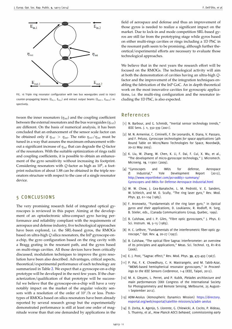
An alternative approach, with respect to the phase sensi-tive CROW based gyro described above, is suggested in [84],where a frequency sensitive gyro based on a multi ring struc-ture is investigated. The advantage of this configuration is theenhancement of the scale factor, keeping equal footprint, withrespect to an RMOG with a single resonator. As sketched inFigure 16 the structure analyzed includes three ring resonatorhaving different radius. Two counter-propagating beams areinjected in the triple ring resonator through a straight waveg-uide. After resonating, the two beams are extracted from theother straight waveguide. The central resonator has a radiusmuch lower than others, while the difference between theother two radii is very small. The coupling coefficient be-
14013- 10
J. Europ. Opt. Soc. Rap. Public. 9, 14013 (2014) F. Dell’Olio, et al.
FIG. 16 Triple ring resonator configuration with two bus waveguides used to inject
counter-propagating beams (Ein,1, Ein,2) and extract output beams (Eout,1, Eout,2) re-
spectively.
tween the inner resonators (ηint) and the coupling coefficientbetween the external resonators and the bus waveguides (ηext)are different. On the basis of numerical analysis, it has beenconcluded that an enhancement of the sensor scale factor canbe obtained only if ηext > ηint. The ratio ηext/ηint must betuned in a way that assures the maximum enhancement with-out a significant increase of ηint that can degrade the Q-factorof the resonators. With the suitable optimization of rings radiiand coupling coefficients, it is possible to obtain an enhance-ment of the gyro sensitivity without increasing its footprint.Considering resonators with Q-factor as high as 106, a foot-print reduction of about 1.88 can be obtained in the triple res-onators structure with respect to the case of a single resonatordevice.
5 CONCLUSIONS
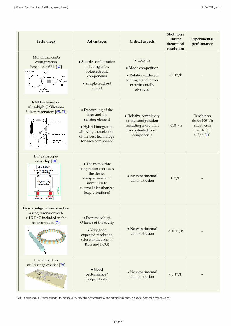
The very promising research field of integrated optical gy-roscopes is reviewed in this paper. Aiming at the develop-ment of an optoelectronic ultra-compact gyro having per-formance and reliability compliant with the requirements ofaerospace and defense industry, five technological approacheshave been explored, i.e. the SRL-based gyros, the RMOGsbased on ultra-high Q silica resonators, the InP gyroscope-on-a-chip, the gyro configuration based on the ring cavity witha Bragg grating in the resonant path, and the gyros basedon multi-rings cavities. All those devices have been criticallydiscussed; modulation techniques to improve the gyro reso-lution have been also described. Advantages, critical aspects,theoretical/experimental performance of each technology aresummarized in Table 2. We expect that a gyroscope-on-a-chipprototype will be developed in the next few years. If the char-acterization/qualification of that prototype will be success-ful we believe that the gyroscope-on-a-chip will have a verynotably impact on the market of the angular velocity sen-sors with a resolution of the order of 10/h or less. Proto-types of RMOGs based on silica resonators have been alreadyreported by several research group but the experimentallydemonstrated performance is still at least one order of mag-nitude worse than that one demanded by applications in the
field of aerospace and defense and thus an improvement ofthose gyros is needed to realize a significant impact on themarket. Due to lock-in and mode competition SRL-based gy-ros are still far from the prototyping stage while gyros basedon either multi-rings cavities or rings including a 1D PhC inthe resonant path seem to be promising, although further the-oretical/experimental efforts are necessary to evaluate thosetechnological approaches.
We believe that in the next years the research effort will befocused on the RMOGs. The technological activity will aimat both the demonstration of cavities having an ultra-high Q-factor and the improvement of the integration techniques en-abling the fabrication of the InP GoC. An in depth theoreticalwork on the most innovative cavities for gyroscopic applica-tions, i.e. the multi-ring configuration and the resonator in-cluding the 1D PhC, is also expected.
References
[1] N. Barbour, and G. Schmidt, “Inertial sensor technology trends,”IEEE Sens. J. 1, 332–339 (2001).
[2] M. N. Armenise, C. Ciminelli, F. De Leonardis, R. Diana, V. Passaro,and F. Peluso, Gyroscope technologies for space applications (4thRound Table on Micro/Nano Technologies for Space, Noordwijk,20–22 May 2003).
[3] K. Liu, W. Zhang, W. Chen, K. Li, F. Dai, F. Cui, X. Wu, et al.,“The development of micro-gyroscope technology,” J. Micromech.Microeng. 19, 113001 (2009).
[4] “Gyroscopes and IMUs for defense, Aerospace& Industrial,” Yole Development Report (2012),http://www.reportlinker.com/p01008831-summary/Gyroscopes-and-IMUs-for-Defense-Aerospace-Industrial.html
[5] W. W. Chow, J. Gea-Banaloche, L. M. Pedrotti, V. E. Sanders,W. Schleich, and M. O. Scully, “The ring laser gyro,” Rev. Mod.Phys. 57, 61–104 (1985).
[6] F. Aronowitz, “Fundamentals of the ring laser gyro,” in Opticalgyros and their applications, D. Loukianov, R. Rodloff, H. Sorg,B. Stieler, eds., (Canada Communications Group, Quebec, 1999).
[7] B. Culshaw, and I. P. Giles, “Fibre optic gyroscopes,” J. Phys. E:Sci. Instrum. 16, 5–15 (1983).
[8] H. C. Lefèvre, “Fundamentals of the interferometric fiber-optic gy-roscope,” Opt. Rev. 4, 20–27 (1997).
[9] B. Culshaw, “The optical fibre Sagnac interferometer: an overviewof its principles and applications,” Meas. Sci. Technol. 17, R1–R16(2006).
[10] E. J. Post, “Sagnac effect,” Rev. Mod. Phys. 39, 475–493 (1967).
[11] P. Pai, F. K. Chowdhury, C. H. Mastrangelo, and M. Tabib-Azar,“MEMS-based hemispherical resonator gyroscopes,” in Proceed-ings to the IEEE Sensors Conference, 1–4 (IEEE, Taipei, 2012).
[12] M. A. Gleyzes, L. Perret, and P. Kubik, Pleiades architecture andmain performances (XXII Congress of the International Societyfor Photogrammetry and Remote Sensing, Melbourne, 25 August–1 September 2012).
[13] ADM-Aeolus (Atmospheric Dynamics Mission) https://directory.eoportal.org/web/eoportal/satellite-missions/a/adm-aeolus
[14] D. Zorita, A. Agenjo, S. Llorente, G. Chlewicki, A. Cocito, P. Rideau,S. Thuerey, et al., How Planck AOCS behaved, commissioning early
14013- 11
J. Europ. Opt. Soc. Rap. Public. 9, 14013 (2014) F. Dell’Olio, et al.
Technology Advantages Critical aspects
Shot noiselimited Experimental
theoretical performanceresolution
Monolithic GaAsconfiguration
based on a SRL [37]
PD
• Simple configurationincluding a fewoptoelectroniccomponents
• Simple read-outcircuit
• Lock-in
•Mode competition
• Rotation-inducedbeating signal never
experimentallyobserved
<0.1/h –
RMOGs based onultra-high Q Silica-on-
Silicon resonators [65, 71] • Decoupling of thelaser and the
sensing element
• Hybrid integrationallowing the selectionof the best technologyfor each component
• Relative complexityof the configurationincluding more than
ten optoelectroniccomponents
<10/h
Resolutionabout 400/h
Short termbias drift =40/h [71]
InP gyroscope-on-a-chip [50]
• The monolithicintegration enhances
the devicecompactness and
immunity toexternal disturbances
(e.g., vibrations)
• No experimentaldemonstration
10/h –
Gyro configuration based ona ring resonator with
a 1D PhC included in theresonant path [70]
• Extremely highQ factor of the cavity
• Very goodexpected resolution(close to that one of
RLG and FOG)
• No experimentaldemonstration
<0.01/h –
Gyro based onmulti-rings cavities [78]
• Goodperformance/footprint ratio
• No experimentaldemonstration
<0.1/h –
TABLE 2 Advantages, critical aspects, theoretical/experimental performance of the different integrated optical gyroscope technologies.
14013- 12

J. Europ. Opt. Soc. Rap. Public. 9, 14013 (2014) F. Dell’Olio, et al.
orbit and pointing manoeuvres (8th International ESA Conferenceon Guidance, Navigation & Control Systems, Karlovy Vary, 2011).
[15] Alphasat I/Inmarsat-XL (Inmarsat-Extended L-band Payload)https://directory.eoportal.org/web/eoportal/satellite-missions/a/alphasat
[16] M. F. Zaman, A. Sharma, Z. Hao, F. Ayazi, “A mode-matchedsilicon-yaw tuning-fork gyroscope with subdegree-per-hour allandeviation bias instability,” IEEE J. Microelectromech. Syst. 17,1526–1536 (2008).
[17] E. A. Donley, “Nuclear magnetic resonance gyroscopes,” in Pro-ceedings to the IEEE Sensors Conference, 17–22 (IEEE, Kona, 2010).
[18] M. N. Armenise, C. Ciminelli, F. Dell’Olio, and V. M. N. Passaro,Advances in gyroscope technologies (Springer-Verlag, Heidelberg,2010).
[19] C. Ciminelli, F. Dell’Olio, C. E. Campanella, and M. N. Armenise,“Photonic technologies for angular velocity sensing,” Adv. Opt.Photon. 2, 370–404 (2010).
[20] O. Kenji, “Semiconductor ring laser gyro,” Japanese Patent # JP60,148,185 (1985).
[21] C. Ji, M. H. Leary, and J. M. Ballantyne, “Long wavelength triangularring laser,” IEEE Photonic. Tech. Lett. 9, 1469–1471 (1997).
[22] R. van Roijen, E. C. M. Pennings, M. J. N. van Stalen, T. van Dongen,B. H. Verbeek, and J. M. M. van der Heijden, “Compact InP-basedring lasers employing multimode interference couplers and com-biners,” Appl. Phys. Lett. 64, 1753–1755 (1994).
[23] T. Krauss, R. M. De La Rue, and P. J. R. Laybourn, “Impact of outputcoupler configuration on operating characteristics of semiconduc-tor ring lasers,” J. Lightwave Technol. 13, 1500–1507 (1995).
[24] M. Sorel, P. J. R. Laybourn, A. Scirè, S. Balle, G. Guiliani, R. Miglie-rina, and S. Donati, “Alternate oscillations in semiconductor ringlasers,” Opt. Lett. 27, 1992–1994 (2002).
[25] H. Cao, H. Ling, C. Liu, H. Deng, M. Benavidez, V. A. Smagley,R. B. Caldwell, et al. “Large S-section-ring-cavity diode lasers:directional switching, electrical diagnostics, and mode beatingspectra,” IEEE Photonic. Tech. Lett. 17, 282–284 (2005).
[26] J. P. Hohimer, and G. A. Vawter, “Unidirectional semiconductorring lasers with racetrack cavities,” Appl. Phys. Lett. 63, 2457–2459(1993).
[27] M. N. Armenise, C. Ciminelli, F. De Leonardis, and V. M. N. Pas-saro, “Quantum effects in new integrated optical angular velocitysensors,” in Proceedings to the 5th International Conference onSpace Optics, 595–597 (ESA, Noordwijk, 2004).
[28] G. L. Vossler, M. D. Olinger, and J. L. Page, “Solid medium opticalring laser,” United States Patent US005408492A (1995).
[29] M. Armenise, Study and design of an integrated optical sensor forminiaturized gyroscopes for space applications (Master’s degreethesis, Bari Polytechnic, 1997).
[30] M. Armenise, and P. J. R. Laybourn, “Design and Simulation ofa Ring Laser for Miniaturised Gyroscopes,” Proc. SPIE 3464, 81–90(1998).
[31] P. J. R. Laybourn, Integrated optoelectronics application in space(ESA International Workshop on Innovation for Competitiveness,Annex I, Noordwijk, 19–21 March 1997).
[32] S. Donati, G. Giuliani, and M. Sorel, “Proposal of a new approachto the electrooptical gyroscope: the GaAlAs integrated ring laser,”Alta Freq. 9, 61–63 (1997).
[33] M. Sorel, P. J. Laybourn, G. Giuliani, and S. Donati, “Progress onthe GaAlAs ring laser gyroscope,” Alta Frequenza - Rivista Di Elet-
tronica 10, 45–48 (1998).
[34] P. J. R. Laybourn, M. Sorel, G. Giuliani, and S. Donati, “Integratedsemiconductor laser rotation sensors,” Proc. SPIE 3620, 322–331(1999).
[35] K. Taguchi, K. Fukushima, A. Ishitani, and M. Ikeda, “Proposal ofa semiconductor ring laser gyroscope,” Opt. Quant. Electron. 31,1219–1226 (1999).
[36] T. Numai, “Analysis of signal voltage in a semiconductor ring lasergyro,” IEEE J. Quantum Elect. 36, 1161–1167 (2000).
[37] M. N. Armenise, M. Armenise, V. M. N. Passaro, F. De Leonardis,“Integrated optical angular velocity sensor,” European PatentEP1219926B1 (2000).
[38] M. Osinski, H. Cao, C. Liu, and P. G. Eliseev, “Monolithically inte-grated twin ring diode lasers for rotation sensing applications,”J. Cryst. Growth 288, 144–147 (2006).
[39] J. Scheuer, “Direct rotation-induced intensity modulation in circu-lar Bragg micro-lasers,” Opt. Express 15, 15053–15059 (2007).
[40] S. Ezekiel, and S. R. Balsamo, “Passive ring resonator laser gyro-scope,” Appl. Phys. Lett. 30, 478–480 (1977).
[41] R. Adar, M. R. Serbin, and V. Mizrahi, “Less than 1 dB per meterpropagation loss of silica waveguides measured using a ring res-onator,” J. Lightwave Technol. 12, 1369–1372 (1994).
[42] M. C. Tien, J. F. Bauters, M. J. R. Heck, D. T. Spencer,D. J. Blumenthal, and J. E. Bowers, “Ultra-high quality factor pla-nar Si3N4 ring resonators on Si substrates,” Opt. Express 19,13551–13556 (2011).
[43] D. T. Spencer, Y. Tang, J. F. Bauters, M. J. R. Heck, and J. E. Bow-ers, “Integrated Si3N4/SiO2 ultra high Q ring resonators,’ in Pro-ceedings to the IEEE Photonics Conference (ICP), 141–142, (IEEE,Burlingame, 2012).
[44] C. Vannahme, H. Suche, S. Reza, R. Ricken, V. Quiring, andW. Sohler, “Integrated optical Ti:LiNbO3 ring resonator for rotationrate sensing”, in Proceedings to the 13th European Conference onIntegrated Optics, WE1 (IEEE, Copenhagen, 2007).
[45] J. T. A. Carriere, J. A. Frantz, S. Honkanen, R. K. Kostuk,B. R. Youmas, and E. A. J. Vikjaer, “An integrated optic gyroscopeusing ion-exchanged waveguides,” in Proceedings to the 16th An-nual Meeting of the IEEE Lasers and Electro-Optics Society, 99–100(IEEE, Tucson, 2003).
[46] G. Li and K. A. Winick, “Integrated optical ring resonators fab-ricated by silver ion-exchange in glass”, in Proceedings to theIEEE/OSA Conference on Lasers and Electro-Optics/InternationalQuantum Electronics Conference and Photonic Applications Sys-tems Technologies, CWA63 (Optical Society of America, San Fran-cisco, 2004).
[47] W. Bogaerts, P. de Heyn, T. Van Vaerenbergh, K. de Vos,S. K. Selvaraja, T. Claes, P. Dumon, et al., “Silicon microring res-onators,” Laser Photonics Rev. 6, 47–73 (2013).
[48] J. K. S. Poon, L. Zhu, G. A. DeRose, and A. Yariv, “Polymer microringcoupled-resonator optical waveguides,” J. Lightwave Technol. 24,1843–1849 (2006).
[49] F. Dell’Olio, C. Ciminelli, M. N. Armenise, F. M. Soares, andW. Rehbein, “Design, fabrication, and preliminary test results of anew InGaAsP/InP high-Q ring resonator for gyro applications,” inProceedings to the IEEE International Conference on Indium Phos-phide and Related Materials, 124–127 (IEEE, Santa Barbara, 2012).
[50] C. Ciminelli, F. Dell’Olio, M. N. Armenise, F. M. Soares, andW. Passenberg, “High performance InP ring resonator for newgeneration monolithically integrated optical gyroscopes,” Opt. Ex-
14013- 13

J. Europ. Opt. Soc. Rap. Public. 9, 14013 (2014) F. Dell’Olio, et al.
press 21, 556–564 (2013).
[51] C. Ciminelli, F. Peluso, and M. N. Armenise, “A new integrated op-tical angular velocity sensor,” Proc. SPIE 5728, 10.1117/12.590421(2005).
[52] H. K. Hsiao, and K. A. Winick, “Planar glass waveguide ring res-onators with gain,” Opt. Express 15, 17783–17797 (2007).
[53] H. Lee, T. Chen, J. Li, K. Y. Yang, S. Jeon, O. Painter, and K. J. Vahala,“Chemically etched ultrahigh-Q wedge-resonator on a siliconchip,” Nat. Photonics 6, 369–373 (2012).
[54] X. Zhang, and A. M. Armani, “Silica microtoroid resonator sen-sor with monolithically integrated waveguides,” Opt. Express 21,23592–23603 (2013).
[55] C. Ford, R. Ramberg, K. Johnson, W. Berglund, B. Ellerbusch,R. Schermer, and A. Gopinath, “Cavity element for resonant mi-cro optical gyroscope,” IEEE Aero. El. Sys. Mag. 15, 33–36 (2000).
[56] X. L. Zhang, and K. J. Zhou, “Open-loop experiments of resonatormicro-optic gyro,” Optoelectron. Lett. 5, 97–100 (2009).
[57] H. Yu, C. Zhang, L. Feng, Z. Zhou, L. Hong, “SiO2 waveguide res-onator used in an integrated optical gyroscope,” Chinese Phys.Lett. 26, 054210 (2009).
[58] L. Guo, B. Shi, C. Chen, and M. Zhao, “A large-size SiO2 waveg-uide resonator used in integration optical gyroscope,” Optik 123,302–305 (2012).
[59] M. Zhao, B. R. Shi, C. Chen, L. J. Guo, R. Zhang, Q. Zhang, “Experi-mental study on resonator micro optic gyroscope,” Proc. SPIE 8191,10.1117/12.900776 (2011).
[60] K. Iwatsuki, M. Saruwatari, M. Kawachi, and H. Yamazaki,“Waveguide-type optical passive ring-resonator gyro using time-division detection scheme,” Electron. Lett. 25, 688–689 (1989).
[61] H. Ma, Y. Yan, Y. Chen, and Z. Jin, “Improving long-term stability ofa resonant micro-optic gyro by reducing polarization fluctuation,”IEEE Photon. J. 4, 2372–2381 (2012).
[62] H. Ma, Z. He, and K. Hotate, “Reduction of backscattering inducednoise by carrier suppression in waveguide-type optical ring res-onator gyro,” J. Lightwave Technol. 29, 85–90 (2011).
[63] K. Suzuki, K. Takiguchi, and K. Hotate, “Monolithically integratedresonator microoptic gyro on silica planar lightwave circuit,”J. Lightwave Technol. 18, 66–72 (2000).
[64] K. Hotate, K. Takiguchi, A. Hirose, “Adjustment-free method toeliminate the noise induced by the backscattering in an opticalpassive ring-resonator gyro,” IEEE Photonic. Tech. Lett. 2, 75–77(1990).
[65] H. Mao, H. Ma, and Z. Jin, “Polarization maintaining silica waveg-uide resonator optic gyro using double phase modulation tech-nique,” Opt. Express 19, 4632–4643 (2011).
[66] L. Feng, M. Lei, H. Liu, Y. Zhi, and J. Wang, “Suppression of back-reflection noise in a resonator integrated optic gyro by hybridphase-modulation technology,” Appl. Optics 52, 1668–1675 (2013).
[67] H. Ma, S. Wang, and Z. Jin, “Silica waveguide ring resonators withmulti-turn structure,” Opt. Commun. 281, 2509–2512 (2008).
[68] C. Ciminelli, F. Dell’Olio, M. N. Armenise, “High-Q spiral resonatorfor optical gyroscope applications: numerical and experimental in-vestigation,” IEEE Photon. J. 4, 1844–1854 (2012).
[69] H. Y. Yu, C. X. Zhang, L. S. Feng, L. F. Hong, and J. J. Wang, “Op-tical noise analysis in dual-resonator structural micro-optic gyro,”Chinese Phys. Lett. 28, 084203 (2011).
[70] C. Ciminelli, C. E. Campanella, M. N. Armenise, “Optical rotation
sensor as well as method of manufacturing an optical rotationsensor,” European Patent EP056933 (2013).
[71] H. Ma, W. Wang, Y. Ren, and Z. Jin, “Low-noise low-delay digitalsignal processor for resonant micro optic gyro,” IEEE Photonic.Tech. Lett. 25, 198–201 (2013).
[72] M. Lei, L. Feng, and Y. Zhi, “Sensitivity improvement of resonatorintegrated optic gyroscope by double-electrode phase modula-tion,” Appl. Optics 52, 7214–7219 (2013).
[73] C. Ciminelli, V. M. N. Passaro, F. Dell’Olio, and M. N. Armenise,“Quality factor and finesse optimization in buried InGaAsP/InP ringresonators,” J. Europ. Opt. Soc. Rap. Public. 4, 09032 (2009).
[74] H. Ma, X. Chang, H. Mao, and Z. Jin, “Laser frequency noise lim-ited sensitivity in a resonator optic gyroscope,” in Proceedings tothe 15th OptoElectronics and Communications Conference, 706–707 (IEEE, Sapporo, 2010).
[75] Z. Jin, G. Zhang, H. Mao, and H. Ma, “Resonator micro optic gyrowith double phase modulation technique using an FPGA-baseddigital processor,” Opt. Commun. 285, 645–649 (2012).
[76] C. Peng, Z. Li, and A. Xu, “Optical gyroscope based on a cou-pled resonator with the all-optical analogous property of electro-magnetically induced transparency,” Opt. Express 15, 3864–3875(2007).
[77] C. Peng, Z. Li, and A. Xu, “Rotation sensing based on a slow lightresonating structure with high group dispersion,” Appl. Optics 46,4125–4131 (2007).
[78] J. Scheuer, and A. Yariv, “Sagnac effect in coupled-resonator slow-light waveguide structures,” Phys. Rev. Lett. 96, 053901 (2006).
[79] Y. Zhang, H. Tian, X. Zhang, N. Wang, J. Zhang, H. Wu, and P. Yuan,“Experimental evidence of enhanced rotation sensing in a slow-light structure,” Opt. Lett. 35, 691–693 (2010).
[80] Y. Zhang, N. Wang, H. Tian, H. Wang, W. Qiu, J. Wang, P.Yuan, “A high sensitivity optical gyroscope based on slow lightin coupled-resonator-induced transparency,” Phys. Lett. A 372,5848–5852 (2008).
[81] M. A. Terrel, M. J. F. Digonnet, and S. Fan “Performance limitationsof a coupled resonant optical waveguide gyroscope,” J. LightwaveTechnol. 27, 47–54 (2009).
[82] J. R. E. Toland, Z. A. Kaston, C. Sorrentino, and C. P. Search,“Chirped area coupled resonator optical waveguide gyroscope,”Opt. Lett. 36, 1221–1223 (2011).
[83] C. Sorrentino, J. R. E. Toland, and C. P. Search, “Ultra-sensitive chipscale Sagnac gyroscope based on periodically modulated couplingof a coupled resonator optical waveguide,” Opt. Express 20, 354–363 (2011).
[84] C. Ciminelli, C. E. Campanella, F. Dell’Olio, C. M. Campanella, andM. N. Armenise, “Theoretical investigation on the scale factor ofa triple ring cavity to be used in frequency sensitive resonantgyroscopes,” J. Europ. Opt. Soc. Rap. Public 8, 13050 (2013).
14013- 14
![Control andSelf-Calibrationof MicroscaleRateIntegrating ... · Gyroscopes(FOGs)andintegrated-opticsgyroscopes[16,17]. The operating principle of optical gyroscopes is based on the](https://img.pdfslide.us/doc/110x75/5fb8aa0c6cc97e21462b9a03/control-andself-calibrationof-microscalerateintegrating-gyroscopesfogsandintegrated-opticsgyroscopes1617.jpg)