Embed Size (px)
Citation preview
Bulletin of the Seismological Society of America. Vol. 67, No. 4, pp. 1029-1050. August 1977
THE EFFECT OF PLANAR DIPPING STRUCTURE ON SOURCE AND RECEIVER RESPONSES FOR CONSTANT RAY PARAMETER
BY CHARLES A. LANGSTON
ABSTRACT
A geometrical ray method is developed for wave calculations involving three- dimensional planar dipping interfaces. Justification for the method is based on analogy with first-motion approximations derived from generalized ray theory where frequency dependence in the reflection-transmission coefficients is related to changes in the complex ray parameter. The method is applied to finding the teleseismic response of an arbitrarily oriented dislocation source in dipping layered media and for receiver calculations which assume an impinging P or S wave be- neath a stack of dipping layers. Source results indicate that wave forms from fast azimuthally varying sources, such as strike-slip faults, are significantly dis- torted from the plane layered case for simple structures. A simple dipping Moho for dips up to 10 ° does not significantly distort vertical and radial P waves for the receiver response. However, due to azimuth anomalies introduced by inter- face dip a significant tangential P component is produced. In addition, the S-wave response becomes a function of source mechanism due to the need for specifying the incident polarization angle. Polarization studies are suggested for finding dipping structure.
INTRODUCTION
A commonly held assumption in many seismological studies is that of horizontally or radially stratified earth structure. Because of the data quality or interpretation techniques generally used, this assumption is quite appropriate for many problems. Recently, however, there has been a small but growing field in seismology which has been concerned with directly modeling the time and amplitude of observed body- wave seismograms from shallow earthquake sources (Helmberger, 1974; Langston and Helmberger, 1975; Filson, 1975; Langston, 1976; Langston and Butler, 1976; Burdick and Mellman, 1976). In these studies estimates of earth structure in the source area are taken from usually inadequate refraction profiles or earthquake travel-time studies. The nature of reflectors in the crustal sections is generally un- known so that simple plane interface models are normally assumed. In some cases of fault orientation, however, radiation pattern coupled with the local crustal structure produces wave effects larger than the direct wave or surface reflections (Langston, 1976). This effectively thwarts any further attempt to extract source information from the seismograms since crustal structure becomes the major factor. In addition, the high precision that these studies strive for virtually guarantees that assumptions in earth structure will always break down at some point making any further improve- ments questionable.
One of the major purposes of this paper will be to investigate the effect of dipping interfaces on the P-wave response of nearby point dislocation sources. This will be done using a fast three-dimensional ray tracing scheme and what is essentially asymp- totic ray theory. The effect of dipping interfaces for the teleseismic receiver problem will also be studied since it falls naturally and easily from the source developments.
1029

1030 CHARLES A. LANGSTON
In particular, the effects of a dipping Moho on the time domain responses of incident P and S waves will be investigated with emphasis on the reverberations in the P wave and the Sp precursor in the vertical S wave.
THEORr
To justify the approach that will be used in the dipping interface formulation it will prove useful to examine the solution characteristics in the plane layered case.
Langston and Helmberger (1975) describe a method for calculating the far-field response for an arbitrarily oriented point dislocation in a horizontally layered elastic medium using generalized ray theory. Setting up a cylindrical coordinate system and specifying fault orientation angles (Figure 1) they develop first-motion ray solutions from asymptotic forms of the potentials for problems which include near-source structure complications. This involves finding suitable approximations of integrals of the type
2 6 Im f(p, v:) = - - - exp [ - - s (pr -~- ~ ,~Th, )]R(p) dp (1)
v Q
z
FIG. 1. Coordinate system in the dislocation formulation. Z is positive downward (Langston and Helmberger, 1975).
where,
S
f ( p , V~) = R ( p ) =
p = YS
Th~ =
Laplace transform variable vertical radiation pattern at the source product of the appropriate generalized reflection and transmission coefficients [ ( l / v 2 _ p2] ,2 seismic ray parameter wave velocity at the source thickness of the ith layer
Frequency dependence is related to how the Cagniard contour, c,
t = pr + v~Th~ (2)
behaves on the complex (p) plane, where (t) is now time. If, for a large span of (t), there is little change in (p) then the integrand of equation (3), in which the contour
EFFECT OF PLANAR DIPPING STRUCTURE ON WAVE RESPONSES 1031
from 0 to + i ~ has been deformed to (c) ,
O(t) = - 2 Im f ( p , v ~ ) - - p ~r e - , t R ( p ) dt dt (3) 7r ~?v ~
varies significantly only at p = po, the geometrical ray parameter. Assuming that the only contribution to the integral comes at p0 and assuming that the distance R = (r 2 + z2) 1/~ in the half-space is large compared to all other layer thicknesses gives the first-motion approximation
O(t ) ~ - - f ( p o , v~)R(po) n . . H ( t - t~o) w , 1;t
(4)
where, vR is the receiver wave velocity. This also assumes, for the moment, no post- critical interactions.
This equation implies that where the receiver is sufficiently far away from the source so that variation in the ray parameter is small, relative to the pulse time length, say at A > 30 ° in the Earth, the response is calculated as if the waves were plane waves. Interactions become frequency-independent for the pre-critical angle case and experience, at most, a complex phase shift for post-critical angle interactions. An implicit assumption in the ray theory for post-critical interactions, however, is that wavelengths are smaller than skin depth penetration for the particular layer so that tunneling effects can be ignored (Richards, 1973, 1976). In the model studies to be presented, critical reflections were usually minor and occurred within the above restriction.
This observation easily leads to a physically realizable model for wave propagation in these types of problems. Since the response reduces to geometrical ray theory, or the first term in asymptotic ray theory, the idea of propagating far-field displacements in the individual layers can be used. Reflections and transmissions will involve trans- forming the displacements into potentials at each interface, multiplying them by the appropriate coefficient, and then transforming back into displacement. Simple energy flux arguments can be used to calculate the geometrical spreading for each ray to find the final amplitude. Thinking in this light, it immediately becomes obvious that interface orientation is merely a detail of geometry and plays no intrinsic role in the wave calculations. I t will be assumed that edges and corners do not contribute to the response. This is not a severe restriction for several reasons. First, theoretically, the effect must be small. If total energy conversion between the direct ray from the source and the structure edge takes place, say over a typical wavelength, so that the edge reradiates all the energy as from another source, it is evident that simple geo- metrical spreading can reduce the edge radiation to a small fraction of the source radiation. Furthermore, by the time edges are encountered by multiple rays in geo- logically feasible structures, the assumptions on layer homogeneity and planar inter- faces become questionable for real earth structure. The assumption will be made, therefore, that rays which interact within a wavelength of an edge are, for all practical purposes, physically unreasonable and will be discarded. This is obviously a problem- oriented restriction. The interest here is to find the effects of moderate interface dips and not edge effects.
The remainder of the theory section will present the techniques for tracing rays in a three-dimensional structure with dipping interfaces and finding their times and amplitudes.
1032 CHARLES A. LANGSTON
RAY TRACING
The three-dimensional tracing algorithm employed here is a noniterative two-step procedure. I t is assumed that all ray paths are great circle paths before arriving or after leaving the heterogeneous area.
This fixes the takeoff angle and ray azimuth in the half-space below the dipping interface structure. Since all interfaces are planar, a simple consecutive application of Snell's law in the suitable local interface coordinate systems is performed, starting in the half-space, to find ray direction unit vectors for each particular ray segment.
/(~ R/ ZoO(Source)
Dip ± ~ . . / / direchon)
~ . .
~ X
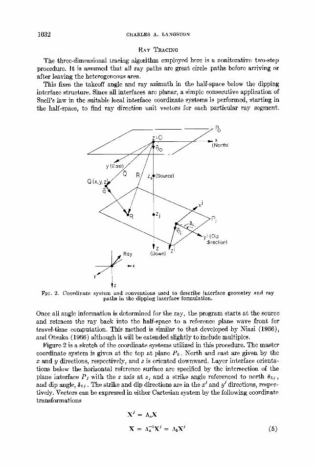
Fie. 2. Coordinate system and conventions used to describe interface geometry and ray paths in the dipping interface formulation.
Once all angle information is determined for the ray, the program starts at the source and retraces the ray back into the half-space to a reference plane wave front for travel-time computation. This method is similar to that developed by Niazi (1966), and Otsuka (1966) although it will be extended slightly to include multiples.
Figure 2 is a sketch of the coordinate systems utilized in this procedure. The master coordinate system is given at the top at plane P0. North and east are given by the x and y directions, respectively, and z is oriented downward. Layer interface orienta- tions below the horizontal reference surface are specified by the intersection of the plane interface P~ with the z axis at zj and a strike angle referenced to north OLd, and dip angle, ~Lj. The strike and dip directions are in the x ~ and yJ directions, respec- tively. Vectors can be expressed in either Cartesian system by the following coordinate transformations
X J = A~X
X = A~~XJ = ADX: (5)

EFFECT OF PLANAR DIPPING STRUCTURE ON WAVE RESPONSES 1033
where,
cos 0L,. sin 0L~. 0 /
Aa = --cos ~Lj' sin 0,.3' cos ~L~" cos 0Lj sin ~ j (6)
sin ~L~" sin eli --sin ~¢ cos 0~¢ cos ~Lj/
Ab = Aa 1 = Aa T,
and where the superscript "T" indicates the matrix transpose. For computational purposes it is useful to define interface unit normal vectors
~j, see Figure 2. In the master coordinate system these are given by
#j = sin 0Li sin ~ j ~ - cos OLs sin ~,~i J + cos ~Lj k. (7)
The first ray segment unit vector or wave front normal can easily be found by taking the negative of equation (7) and using a wave front "strike", 0L., of 90 ° plus the station azimuth and "dip", ~L~, found from Snell's law
sin i - p Y
= i ( 8 )
where, i is the vertical incident angle, v is the local wave velocity, and p is the ray parameter in seconds per kilometer.
Ray segment unit vectors are found by first rotating the previous unit vector into the next interface coordinate system, using equation (6), and applying Snell's law at the interface for the particular interaction. If ~b is the ray segment unit vector before interaction and, ~ , the unit vector after interaction (in the interface coordinates), then the components of ~a are given by
qal = aqbl
qa2 =- t~qb2
qa= ~=sgn(qb~)cOSia {~reflection I transmission I
(9)
where, i~ is the incident angle after interaction and
sin ia - (q 1 + q 2) 1/2"
The local incident angles are found from Snell's law
sin i~ sin io (10)
Yb Ya

1034 C H A R L E S A . L A N G S T O N
and
cos ib = ~b" ~jJ. (11)
After interaction the new ray unit vector is rotated back into the master system and this same process repeated at the next interface.
Ray segment lengths are computed by a simple application of geometry. Starting at the source and changing the sign of all ray segment unit vectors for the reverse direction, the problem becomes one of finding the ray intersection point at the next interface given a starting location. Figure 2 shows a sketch of the geometry where the distance between points Q and R and the location of R are desired. A parametric equation for the vector R is (in the master coordinates)
R = Q + @
= (Xo, yo, Zo) + u ( q l , q~, q3). (12)
The equation for the plane P j is given by
~1 i x + V2jY + ~3j(z-- zs) = 0 (13)
where,
~" = (~ l j , V2j, V3j).
The solution is
U = ~ j ( Z j - - Z0) - - ~ lsXo - - y25y0
(i. #~) (14)
The modulus of u gives the desired distance and equation (12) gives the location of point R.
Travel time to the reference wave front is then given by
T = ~'~dl/v~ (15) l = l
where, l is the index of ray segments, d~ is the length of the / th leg, and vt the local velocity.
AMPLITUDE
Calculation of ray amplitude falls naturally into two parts. Far-field displacements are computed in the master coordinate system starting at the source, are rotated into the local interface coordinates, and are inverted to wave potentials. The appropriate reflection or transmission coefficient is multiplied in and the resultant displacement after interaction found by the potential representations. The reflection or transmission coefficient may contain a complex phase shift and is handled by two displacement vector representations. After the ray has been traced in this manner a geometrical spreading correction is applied.

EFFECT OF PLANAR DIPPING STRUCTURE ON WAVE RESPONSES 1035
Far-field displacements are related to the wave potentials, in the cylindrical coordi- nate system of Figure 1, by
W = - n . e 5 + pf i
Q = - p ~ - n0 e
V = p)~ (16)
where,
I +1 downgoing ray leg (z increasing)
[ - 1 upgoing ray leg (z decreasing)
and 5, ~, and ~ are the time derivatives of the local P, S V , and S H wave potentials (Langston and Helmberger, 1975). Wave displacements are resolved into local vertical, radial, and tangential displacements relative to the ray direction and interface co- ordinates so that the local potential can be resolved.
Reflection and transmission coefficients are those used by Helmberger (1968) and are allowed to become complex for post-critical reflections or transmissions. The general first motion or asymptotic ray approximation for post-critical interface interactions is given by
1 ( ~ R e [ R ( p ) ] ~ ( t - tR) o ( t ) = y. t.
Im[R(p)] 1 ~ (18) ~- (t t~) )
where, L is the geometrical spreading factor, R ( p ) is a complex reflection or trans- mission coefficient, tR is the arrival time, and the input time history is a Dirac delta function (Arons and Yennie, 1950; Helmberger, 1968). I t is well known that equation (18) is equivalent to applying a complex phase shift to the incident time function in the Fourier domain (Arons and Yennie, 1950; Choy and Richards, 1975). However, instead of applying a complex phase shift to the time history at each interaction by using an FFT, a simple decomposition of the displacement vector can be done which uses certain properties of equation (18). This will avoid the problem of finding dis- placement vectors as a function of time since there are cases in which, say, a local S V wave will be distorted by a phase shift but S H will not. Because coordinate rota- tions assume the same time function for all vector displacements, the problem be- comes non-separable when done with simple phase shifts. Recognizing that the second term on the right in equation (18) is a definition for the Hilbert transform, H, (Brace- well, 1965) and generalizing the time history to S( t ) gives
O~(t) = O ( t ) * S ( t ) = ~ e [ R ( p ) ] S ( t - tR) -t- Im [R(p ) ]H[S( t - tR) . (19)
Equation (19) demonstrates that the total response at an interface can be broken into two factors which have separate time functions. A further complex phase shift behaves like
o~(t) = o l ( t ) * o ( t ) (20)

1036 CHARLES A. LANGSTON
in which a second Hilbert transform of the transform time function would have to be performed. Fortunately, this gives
H { H [ S ( t - tR)]} = - S ( t - tR). (21)
So, in general, only the time function and its Hilbert transform need be computed once for an arbitrary number of complex phase shift interactions. A typical time func- tion and its Hilbert transform in this study is displayed in Figure 3. The Hilbert transform is distinctly noncasual but this problem is minor when the instrument re- sponse is convolved with it (see Choy and Richards, 1975, for example).
The tack taken, therefore, is to consider two displacement vectors for the two types of time functions. Potentials for the "undistorted" and "distorted" time functions, say ¢~v and ¢JD, are found by applying equations (16) to the two displacements. A recursive relation can be written for finding the "new" potentials after interaction in
S(t)
[- 50 sec --j
F~G. 3. A typical effective time function, S(t), and its Hilbert transform, H[S(t)].
terms of the "old". Consider before interaction
¢~o(t) = ¢~uoS(t) -t- ~DoH[S(t)]. (22)
Substituting this into equation (19) (omitting geometrical spreading) gives for the "new" potential ~b.(t)
~b.(t) = ~bu0(Re [R(p)]S(t) + Im [R(p)]H[S(t)])
-t-~D,(Re [R(p)]H[S(t)] - Im [R(p)]S(t) ) (23)
which can be collected into "new" undistorted and distorted potentials
~bv~ = Re [R(p)l~bu0 - Im [R(p)]~bD0
~b, n = Re [R(p)]~bD0 ~- Im [R(p)]~bv 0 . (24)
These are then transformed into new distorted and undistorted displacements and propagated to the next interaction.
Geometrical spreading is computed using a recursive formulation which considers one interface at a time. A combination of energy conservation and first-motion methods is used to compute the "effective" source distance and amplitude for the wave after interaction. Consider the single interface in Figure 4 separating media 1 and 2. From the first-motion approximation of the generalized ray which describes this interaction

EFFECT OF PLANAR DIPPING STRUCTURE ON WAVE RESPONSES 1037
the geometrical spreading effect is given by (Helmberger, 1968; Langston, among others)
( )( -.-,,, f Zl Z2 Zl Z2Y]vl / ~ L = + + v ,, jj .
1976;
(25)
Expressing the distances in terms of the geometrical ray paths gives
f 2 / 2 2 - - 2 2 X'~ 112
r
Virtual Mi source z~, Source
\ " R R o" , \ Ra
\ \ ~ x V I 1 %
V 2 t z ~ 2 R2
z 2 M2
FIG. 4. Interface geometry used in the geometrical spreading development.
(26)
The spreading effect can equivalently be found by considering conservation of energy (Hron and Kanasewich, 1971 ) from the source at M1 to point M2 by
A/dA(M2) ~// dA1 (27) L = "V dA2 dA(M1)
where, dA1 and dA2 are the differential areas at the interface in media 1 and 2. Since the media are homogeneous and the wave fronts are spherical
dAi - R1.2 (28) dA(M1)
Substituting this into equation (27) and setting (27) equal to equation (26) gives
where,
dA(M2) R12 -4- RS~l -4- RiR272 dA2 R12
,~1 ..~. ( i'] ~_..~l ~ 2
2 2 2 2
7 2 = v i v 2 ~ 2 2
(29)

1038 CHARLES A. LANGSTON
Considering the spreading from the virtual source,
dA(M2) dA2 dA(M2) dA(Mo) dA(Mo) dA2
- R ~ = (Ro + R~) ~, (30)
and using
dA2 = Ro 2 (31) dA(Mo)
gives
[-dA I M ~7~12 [ ~ 2 j l R~ + R2 [. dA2 J
Ro = IdA(M2) 11 (32) L3- 7
The amplitude of the effective source is found by equating the spreading effect calcu- lated by equation (26) with the following
C02R 2 = R12 -~- R2~1 + RIR25,2 (33)
which gives,
R R ~1/2 Co = [R12 + R2 ~1+ 1 ~'2J : R
(34)
Thus, for a given interface and given ray leg lengths (R1 and R2), an effective source distance and amplitude can be found to give the overall geometrical spreading.
The last ray leg length, R f , is assumed to be much larger than any previous ray leg so that the final geometrical spreading reduces to
where, n is the index of the half-space, n - 1 the layer just above, and Cf the accumu- lated effective source strength. To normalize this expression to the geometrical spread- ing curve given in Langston and Helmberger (1975), multiply L by the ratio of the source ~ to the half-space ~,. assuming the receiver ray parameter, pr~el . . . . Explicitly
L~o,~ = (vv,]/ \ . L_ . R~H (36) \~vs/ preceiver Rf
where, RL~ is the appropriate value from the curve given in Langston and Helmberger (1975).
NUMERICAL RESULTS FOR SOURCES
The effects of interface dip on the response of imbedded point dislocations were investigated for two simple crustal models. In the first study various sources were

EFFECT OF PLANAR DIPPING STRUCTURE ON WAVE RESPONSES 1039
placed in a 30-km-thick (zi) crust with the Moho dipping 10 °. Table 1 displays the earth model parameters. A particular goal was to investigate the effect of Moho dip on the reverberations after pP and sP. Other questions concerned the magnitude of wave-form change s near nodes and any increased wave complexity which could be mistaken for multiple sources. The three fundamental point dislocation sources (Langston and He!mberger, 1975) were tested; vertical strike-slip, vertical dip-slip, and 45 ° dipping thrust faults were placed at a depth of 10 km in the crust layer. The strike of the dipping Moho interface was chosen in one case to coincide with the strike of the fault plane and in another case to be 45 ° clockwise of fault strike. This latter case removed any symmetry conditions between radiation pattern and structure effects that the first trial had. Figures 5 and 6 show the results of these model studies. Figure 5 shows vertical strike-slip P responses at eight station azimuths computed using 40 rays with a ray parameter of 0.075 sec/km. Structure at the receiver was assumed to be a half-space. Three seismograms are shown for each azimuth and cor- respond from top to bottom, to the horizontal, 10 ° dipping N-S striking, and 10 ° dipping N45°E striking interface cases, respectively. The fault strikes north-south
T A B L E 1
CRUSTAL STRUCTURES USED FOR SOURCE AND RECEIVER CALCULATIONS
Va (km/sec) : Va (km/sec) p (gm/cal*) z./(km)
1. D@pingMoho
6.0 3.5 2.7 30.0 8.0 4.5 3.2 - -
2. SedimentaryWedgeOverCrust
4.5 2.5 2.5 5.0 6.0 3.5 2.7 - -
and is left-lateral. The time function is a simple trapezoid 4 sec in duration with equal rise and fall-off times of 1 sec. A Futterman (1962) "Q" operator, using a value of one (1) for T/Q, and the WWSSN 15-100 instrument response are included. Major phases are indicated for the fiat case at 45 ° azimuth. Although sP is theoretically about twice the amplitude as direct P, the combined effect of the instrument response and interference with pP for this source depth reduces it to the same effective ampli- tude as direct P. The smaller oscillations after sP are the combined effect of many crustal reverberations adding in phase with no single outstanding ray. The effect of Moho dip is not very pronounced for station azimuths in radiation maxima at 45 °, 135 °, 225 °, and 315°; changes occur in overall amplitude with the reverberations being slightly distorted. Nodal azimuths show the greatest changes in wave forms, however. Although the azimuth anomaly is at most 7 ° (see Table 2) for P, pP, and sP, the "sin 20" term in the P-SV radiation pattern for strike-slip dislocations pro- duces substantial amplitude in the final P response at what was previously the hori- zontal case node. Furthermore, since the azimuth anomalies of the crustal reverbera- tions range to greater than 100 ° these arrivals are generally enhanced because of radiation pattern and become major phases in the P wave form after sP. These major structure effects could easily be mistaken for source complications because of their size and variation with azimuth. The distortion introduced into a standard first- motion study would be small since the total angle anomaly for the direct ray is small.

1040 CHARLES A. LANGSTON
Detailed wave form analysis for source structure would be generally difficult unless independent constraints could be placed on the source crustal structure.
P responses from a vertical dip-slip source in the same structure (Figure 6) are affected only slightly. Since the radiation pat tern for this orientation goes as "sin 0" instead of "sin 20", variations in ray takeoff angles and azimuth have smaller effects on the wave form. Major wave distortions occur a t the node as before, but amplitudes are small which makes it unlikely for these effects to be generally observable. The
]
VERTICAL STRIKE- SLIP / Dipping Moho. t Az o Az o
o
_•--sP .80 .80
© o
90 o o 2700 0
.80 .70
F~G. 5. Synthetic seismograms for a left-lateral vertical strike-slip fault situated at 10-km depth and striking N-S in a one-layer crust with a dipping Moho (Table 1). At each station azi- muth three synthetics are shown for the flat, 10°E dipping, and 10°SE dipping Moho cases, from top to bottom, respectively. Amplitude is shown to the right of each case and maj or phases indicated for the 45 ° azimuth wave form.
reverberat ions af ter sP change slightly in t iming for the down-dip direction and dis- appear in up-dip directions. Rays which leave the focal area in the up-dip direction have fiat trajectories and, because of the vertical radiation pa t te rn for this dip-slip source, have little amplitude. The basic wave form is preserved with only small am- plitude variations.
A 45 ° thrus t fault orientation in the dipping Moho structure shows virtually no wave-form and ampli tude variat ion since there are no vertical nodal planes. Therefore, it is not presented as a figure.
To simulate the effect of a source under one side of a sedimentary basin, a wedge of low velocity material 5 km thick (zj) was placed over a half-space having crustal
EFFECT OF PLANAR DIPPING STRUCTURE ON WAVE RESPONSES 1041
VERTICAL DIP-SLIP 1 Dipping Moho.
o Az O Az A // o. o
2 2 5 ° ~ 5.96
5 5 '
I~ 50 sec
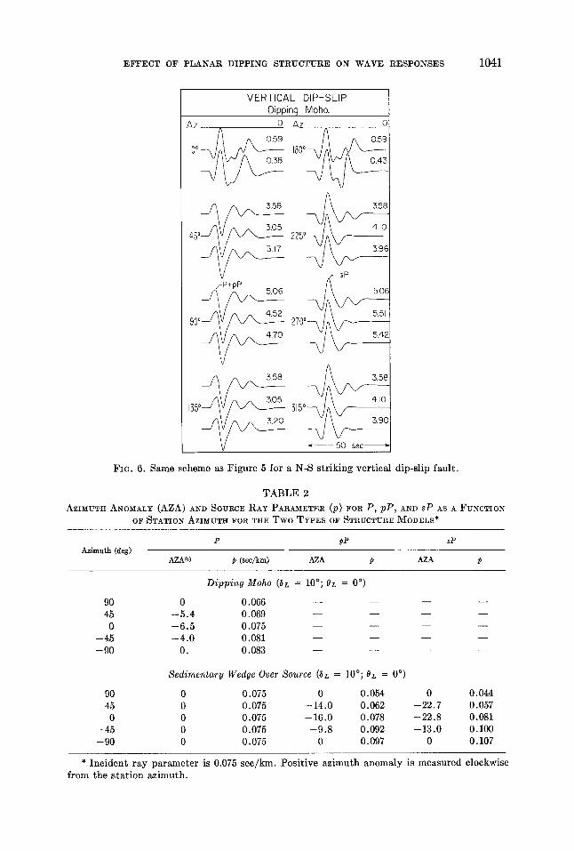
FIG. 6. Same scheme as Figure 5 for a N-S striking vertical dip-slip fault.
T A B L E 2
AZIMUTH ANOMALY (AZA) AND SOURCE RAY PARAMETER (p) FOR P, pP, AND sP AS A FUNCTION OF STATION AZIMUTH FOR THE T w o TYPES OF STRUCTURE MODELS*
P pP sP Azimuth (deg)
AZA(o) p (sec/km) AZA p AZA p
Dipping Moho (~L = 10°; 0L = 0 °)
90 0 0.066 . . . . 45 - -5 .4 0.069 . . . .
0 - -6 .5 0.075 . . . . --45 - -4 .0 0.081 . . . . --90 0. 0.083 . . . .
Sedimentary Wedge Over Source ~L = 10°; 0L = 0 °)
90 0 0.075 0 0.054 0 0.044 45 0 0.075 --14.0 0.062 --22.7 0.057
0 0 0.075 --16.0 0.078 --22.8 0.081 --45 0 0.075 - -9 .8 0.092 --13.0 0.100 --90 0 0.075 0 0.097 0 0.107
* I n c i d e n t r ay p a r a m e t e r is 0.075 s e c / k m . Pos i t ive a z i m u t h anoma ly is m e a s u r e d clockwise f rom the s t a t i o n az imu th .

1042 CHARLES A. LANGSTON
wave velocities. The source depth was chosen to be 10 km with interface dips and strikes taken and varied in the same manner as the dipping Moho case. Only 12 rays representing the direct wave, primary reflections, and first reverberations in the layer were used to avoid edge effects and to simplify calculations. This is justified since the primary purpose of this study was to investigate the effect of the dipping interface on pP and sP relative to direct P.
Figure 7 demonstrates the major wave-form distortions, relative to the flat case, that the response from a vertical strike-slip dislocation undergoes. In nearly all cases, the major phases pP and sP have significant amplitude differences to change the
Az
O o - -
P~
45°@
VERTICAL STRIKE- SLIP Layer above source
0.69
0.42
0.69
Az o
180° ~ 0.69_
0.69
2 2 5 ° ~
0 0
0 270 ° 0 0.43
Fza. 7. Same scheme as Figure 5, only for the strike-slip source under a wedge of low-velocity material (Table 1).
character of the final P wave form. At azimuths corresponding to direct P nodes, the resultant wave forms are constructed entirely from up-going rays and are as large as wave forms in radiation maxima directions. Table 2 shows that azimuth anomalies for the principle reflections are large and, coupled to the "sin 20" radiation pattern, produce the large ray amplitudes.
The vertical dip-slip source orientation, shown in Figure 8, is again much less af- fected by the structure complications. Note, however, the large frequency change in the character of the P wave forms at the nodal azimuths. This effect is caused by the interference of reflections from both the bottom and top of the sedimentary wedge. The total amplitude is an order of magnitude smaller than typical values for this orientation, however, so would again generally be difficult to observe.
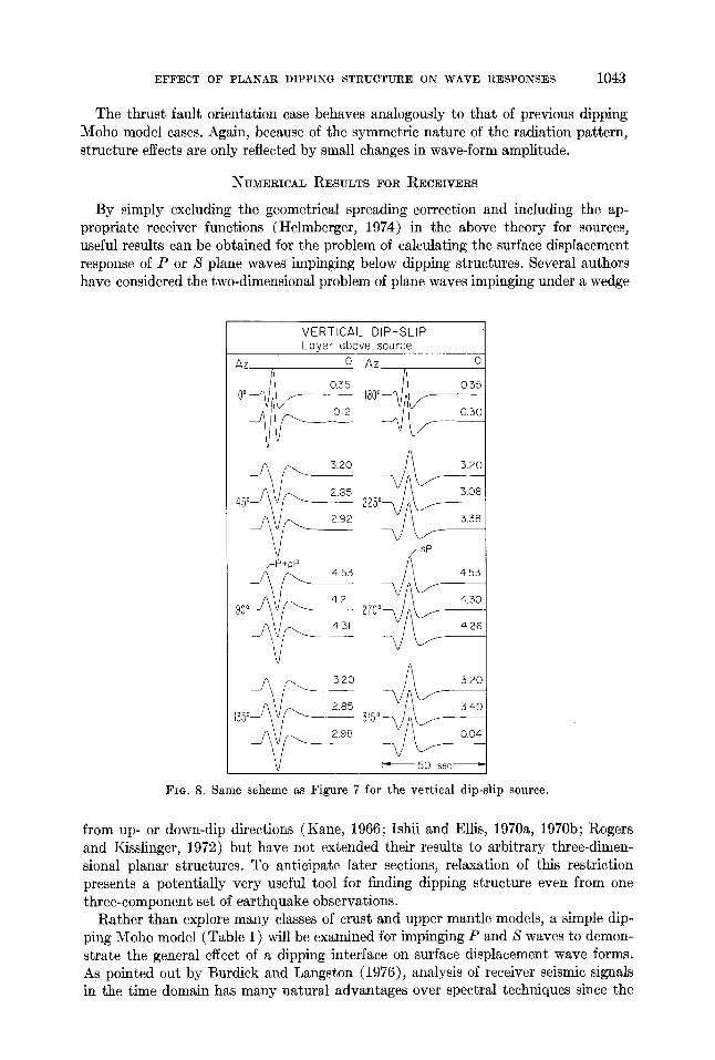
EFFECT OF PLANAR DIPPING STRUCTURE ON WAVE RESPONSES 1043
The thrust fault orientation case behaves analogously to that of previous dipping Moho model cases. Again, because of the symmetric nature of the radiation pattern, structure effects are only reflected by small changes in wave-form amplitude.
NUMERICAL RESULTS FOR RECEIVERS
By simply excluding the geometrical spreading correction and including the ap- propriate receiver functions (Helmberger, 1974) in the above theory for sources, useful results can be obtained for the problem of calculating the surface displacement response of P or S plane waves impinging below dipping structures. Several authors have considered the two-dimensional problem of plane waves impinging under a wedge
VERTICAL DIP-SLIP Layer above source
Az 0 Az 0
~ j ~ ~ 0.3o
3.20
2.s5 225°--/A p ,z 3.o8 d5 °
fsP /-P+PP 4.53 4.53
~ 4.21 ~ 9 0 ° ~ 270° 4.31
298 3 1 5 ° ~
I= 50 sec "1
Fie. 8. Same scheme as Figure 7 for the vertical dip-slip source.
from up- or down-dip directions (Kane, 1966; Ishii and Ellis, 1970a, 1970b; Rogers and Kisslinger, 1972) but have not extended their results to arbitrary three-dimen- sional planar structures. To anticipate later sections, relaxation of this restriction presents a potentially very useful tool for finding dipping structure even from one three-component set of earthquake observations.
Rather than explore many classes of crust and upper mantle models, a simple dip- ping Moho model (Table 1 ) will be examined for impinging P and S waves to demon- strate the general effect of a dipping interface on surface displacement wave forms. As pointed out by Burdick and Langston (1976), analysis of receiver seismic signals in the time domain has many natural ~dvantages over spectral techniques since the

1044 CHARLES A. LANGSTON
timing and amplitude of observed phases can be interpreted directly with all modeling assumptions presented in a clearer manner.
Figure 9 shows the surface response for an impinging P wave under the simple one- layer crust. Moho dip and strike was taken arbitrarily to be 10 ° and 0°N, respec- tively. The responses for the vertical, radial, and tangential components are shown for five back azimuths with the flat layer response shown at top. The three displace- ment components are those relative to the true source back azimuth and with the tangential component sense being that of Figure 1. Schematic delta functions are shown for the wave forms of the 45 ° back azimuth case to demonstrate the relative
P-Waves Vertical I Radial I Tangential
Horizontal case
9 0 0 ~ ~ DIp =lO°E 0 STRIK E= 0 ° N
PpS m p+ PPPmP PpSms PP A PpPms
~/ ~PP Prn s pV s /'ppp:; pSmS
o
I~ 40 sec
FIG. 9. Surface displacement synthetic seismograms for the flat and 10°E dipping Moho cases for an impinging plane P wave under the one-layer crust model (Table 1). From left to right, at each back azimuth, are the vertical, radial, and tangential displacement components, respec- tively. Schematic delta functions indicate the time and relative amplitude of the major phases for the 45 ° back azimuth case.
amplitudes and timing of the various crustal phases which comprise these wave forms. The notation describing each phase is that of B£th and Steffafisson (1966). Lowercase letters represent ray segments of either P or S modes which travel up in the layer, and capitals represent down-going ray legs, except for the first capital which is the im- pinging wave type. The subscript " m " designates a topside reflection from the Moho. The incident time function is taken to be a simple trapezoid 3 sec in duration with equal rise and falloff times of 1 see. Convolution with a P-wave Q operator (T/Q =
1.0), produces a typical effective time function appropriate for simple deep focus events (Burdick and Helmberger, 1974). An incident P ray parameter of 0.06 sec/km was used in all calculations.
The effect of the dipping Moho on the vertical component is minor and is reflected mainly in small amplitude variations of direct P. Secondary phases are small with the only other important arrival being the first P reverberation.

E F F E C T OF P L A N A R D I P P I N G S T R U C T U R E ON W A V E R E S P O N S E S 1045
The radial component shows some discernible variation with back azimuth but the character of the wave form remains approximately the same except for the up-dip case at 90 °. Rays interact with the free surface and Moho with generally smaller local incident angles which produce smaller reflections and conversions. Table 3 lists the azimuth anomaly and surface ray parameter for each ray shown in Figure 9 and demonstrates this effect at 90 ° .
By far, the most pronounced effect of interface dip is the production of a distinct and complicated tangential P component. Because of the different and large azimuth anomalies that each ray experiences (see Table 3), the tangential wave form is con- trolled by the interference of these arrivals. Although the amplitude, for this case, is generally about one-fifth that of the radial component, it should be possible to observe the effect of a tangential component from low-noise, high-quality long-period earth- quake recordings by vectorally rotating the horizontal P components into the known back azimuth for a particular event. Note that tangential P waves at southern back azimuths can be obtained by taking the negative of those in Figure 9 and reflecting
T A B L E 3
AZIMUTH ANOMALY (AZA) AND SURFACE RAY PARAMETER (p) FOR P RECEIVER RESPONSE
RAYS COMPUTED WITH AN INCIDENT RAY PARAMETER OF 0 . 0 6 SEC/KM AND
VARIOUS BACK AZIMUTHS
Ray
90 ° 45 ° 0 o --45 ° --90 °
AZA(o) P AZA P AZA P AZA P AZA P sec/km) (sec/km) (sec/km) (sec/km (sec/km)
Pp 0 0.051 -6 .3 0.054 -7 .6 0.061 --4.7 0.060 0 0.067 Ps 0 0.029 -29.2 0.044 -26.3 0.067 -14.3 0.083 0 0.089 PpPmp 180 0.000 --72.4 0.048 --45.3 0.085 -21.9 0.108 0 0.116 PpPms 180 0.027 --90.4 0.060 -54.0 0.102 -25.8 0.129 0 0.139 PpSmp 180 0.027 --90.3 0.000 -53.4 0.100 -25.3 0.126 0 0.134 PpSms 180 0.048 -101.5 0.077 -59.8 0.119 --28.4 0.148 0 0.158 PsSms 180 0.070 -108.6 0.095 --64.0 0.137 -30.2 0.166 0 0.176
about the east-west line. For example, the tangential P wave at 135 ° would be the negative of the response at 45 ° .
Figure 9 suggests that dipping structure could be studied by using one of two techniques, and preferably, both together. First, comparisons of radial P waves as a function of back azimuth could be performed in order to find systematic differences in the timing and amplitude of the crustal reverberations and conversions. Second, and perhaps more definitive, the existence of tangential P waves would give an im- mediate indication that dipping structure is a factor. Their amplitude and complexity as a function of azimuth would give the direction and amount of dip for the interface. Ideally, as much data as possible should be included in such studies, so that both wave forms should be used together. However, because of their relative amplitude, tangential P waves might be difficult to extract from seismic or digital noise unless high signal-to-noise signals are used.
To demonstrate the validity and existence of tangential P waves, Figure 10 displays a P-wave rotation for an intermediate depth event (h = 91 km, ISC) which occurred in Chile and was recorded at Victoria, British Columbia (VIC). Note that the vertical P wave is relatively simple for nearly 25 sec until the surface reflections at the source become apparent. The north-south and east-west components are clearly not identi- cal, as they should be from horizontal layer theory, but contain major impulsive
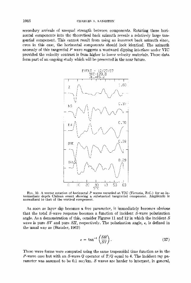
1046 CHARLES A. LANGSTON
secondary arrivals of unequal strength between components. Rotating these hori- zontal components into the theoretical back azimuth reveals a relatively large tan- gential component. This cannot result from using an incorrect back azimuth since, even in this case, the horizontal components should look identical. The azimuth anomaly of this tangential P wave suggests a westward dipping interface under VIC provided the velocity contrast is from higher to lower velocity materials. These data form part of an ongoing study which will be presented in the near future.
EVENT - 1 2 / 2 7 / 8 7 BAZ=129.8 0EL=85.2
r ~ l , l , l , l , f , I 1 .O0
0 .37
0 .89
0.29
0 10 20 30 40 50 80 SEC
FIG. 10. A vector rotation of horizontal P waves recorded at VIC ~ictoria, B.C.) for an in- termediate depth Chilean event showing a substantial tangential component. Amplitude is no~alized to that of the vertical component.
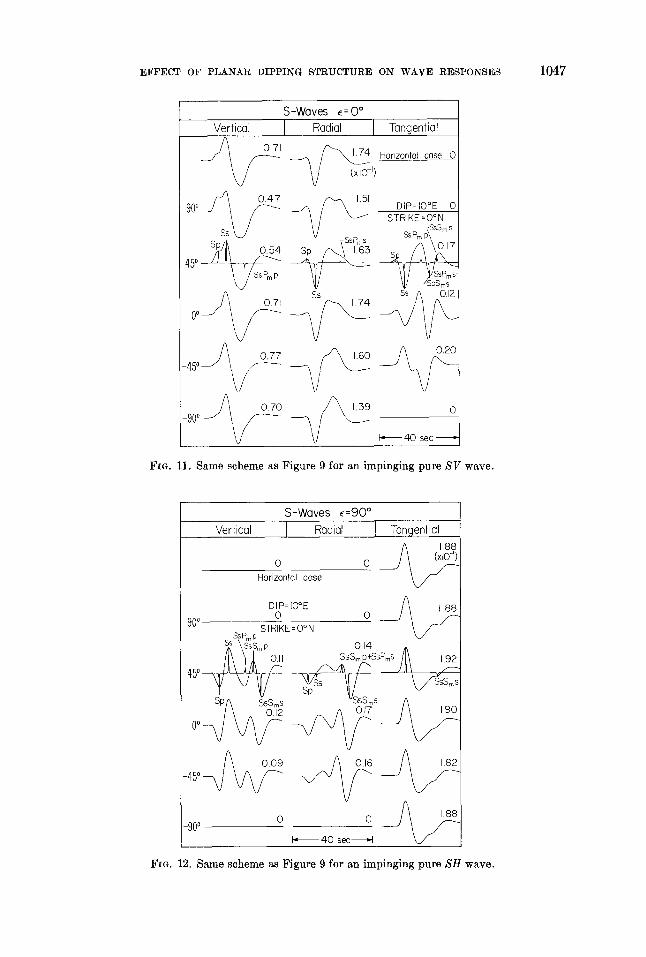
As soon as layer dip becomes a free parameter, it immediately becomes obvious tha t the total S-wave response becomes a function of incident S-wave polarization angle. As a demonstration of this, consider Figures 11 and 12 in which the incident S wave is pure SV and pure SH, respectively. The polarization angle, e, is defined in the usual way as (Stauder, 1962)
SH) (37) = tan -1 ~ •
These wave forms were computed using the same trapezoidal time function as in the P-wave case but with an S-wave Q operator of T/Q equal to 4. The incident ray pa- rameter was assumed to be 0.1 see/kin. S waves are harder to interpret, in general;
EFFECT OF PLANAR DIPPING STRUCTURE ON W A V E RESPONSES 1047
S-Waves • : 0 ° Vertical I Radial I Tangential
1.74 Horizontal case 0 ~/ ~,/ 900 / ~ 0.47 DIP= IO°E 0
~/" S s ~ - STRIKE =O°N
Sp~ 0.54 ?SSPmS SsPm p(SSm s sp /~\ 1.6s /q\o.17 45o__Z;UL~_/~ ~ / ~,.._~ s ~
V SsPmp ~ zSpSms
o
I', 40 sec ,"
FIG. 11. Same scheme as Figure 9 for an impinging pure S V wave.
S-Waves ~=90 ° Vertical I Radial I Tangential
A [88 o o _ 2 ~
Horizontal case
DIP:iO°E 0 0
90° STRIKE = 0 ° N Ss Pm P
s2 \~ssmp O J4 . [ l \ ~ I O.II SSSrnp+SSPmS ~\ 1.92
0°-7 V ~ / ~ 0.09
_90o 0 0
I '~ 40 see I"1
FIG. 12. Same scheme as Figure 9 for an impinging pure S H wave.
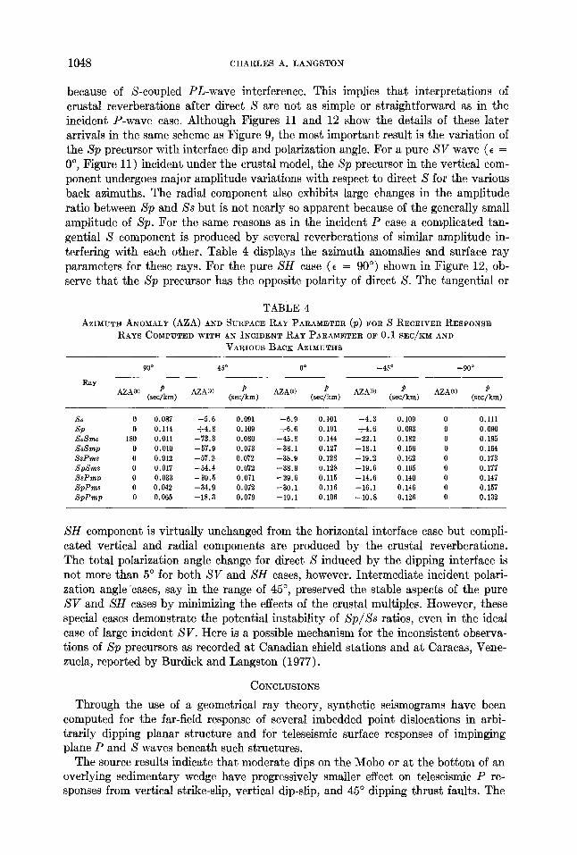
1048 C H A R L E S A. L A N G S T O N
because of S-coupled PL-wave interference. This implies that interpretations of crustal reverberations after direct S are not as simple or straightforward as in the incident P-wave case. Although Figures 11 and 12 show the details of these later arrivals in the same scheme as Figure 9, the most important result is the variation of the Sp precursor with interface dip and polarization angle. For a pure SV wave (E = 0 °, Figure 11 ) incident under the crustal model, the Sp precursor in the vertical com- ponent undergoes major amplitude variations with respect to direct S for the various back azimuths. The radial component also exhibits large changes in the amplitude ratio between Sp and Ss but is not nearly so apparent because of the generally small amplitude of Sp. For the same reasons as in the incident P case a complicated tan- gential S component is produced by several reverberations of similar amplitude in- terfering with each other. Table 4 displays the azimuth anomalies and surface ray parameters for these rays. For the pure SH case (e = 90 °) shown in Figure 12, ob- serve that the Sp precursor has the opposite polarity of direct S. The tangential or
TABLE 4 AZIMUTH ANOMALY (AZA) AND SURFACE RAY PARAMETER (p) FOR S RECEIVER RESPONSE
RAYS COMPUTED WITH AN INCIDENT RAY PARAMETER OF 0.1 SEC/KM AND
VARIOUS BACK AZIMUTHS
Ray
90 ° 45 ° 0 o _45 o --90 °
AZA(O) P AZA(0) P AZA(o) P AZA(O) P AZA(O) P (sec/km) (sec/km) (sec/km) (sec/km) (sec/km)
,Ss 0 0.087 - 5 . 0 0.091 - 6 . 9 0.101 - 4 . 3 0.109 0 o . n l ~qp 0 0.114 q-4.8 0.109 -I-6.6 0.101 -}-4.6 0.098 0 0.090 ,Ss~ms 180 0.011 -73 .3 0.080 -45.8 0.144 -22.1 0.182 0 0.195 ,SsSmp 0 0.010 -57.9 0.073 -38.1 0.127 -18.1 0.156 0 0.164 f-qsPms 0 0.012 -57.2 0.072 -38.9 0.128 -19.2 0.162 0 0.173 ,SpSms 0 0.017 -54.4 0.072 -38.9 0.128 -19.6 0.165 0 0.177 ,SsPm~ 0 0.033 -39.5 0.071 -29.6 0.115 -14.6 0.140 0 0.147 ~qpPms 0 0.042 - 34.9 0.072 -30.1 0.116 - 16.1 0.146 0 0.157 ,SpPmp 0 0.065 -18.3 0.079 -19.1 0.106 -10 .8 0.126 0 0.132
SH component is virtually unchanged from the horizontal interface case but compli- cated vertical and radial components are produced by the crustal reverberations. The total polarization angle change for direct S induced by the dipping interface is not more than 5 ° for both SV and SH cases, however. Intermediate incident polari- zation angle "cases, say in the range of 45 ° , preserved the stable aspects of the pure SV and SH cases by minimizing the effects of the crustal multiples. However, these special cases demonstrate the potential instability of Sp/Ss ratios, even in the ideal case of large incident SV. Here is a possible mechanism for the inconsistent observa- tions of Sp precursors as recorded at Canadian shield stations and at Caracas, Vene- zuela, reported by Burdick and Langston (1977).
C O N C L U S I O N S
Through the use of a geometrical ray theory, synthetic seismograms have been computed for the far-field response of several imbedded point dislocations in arbi- trarily dipping planar structure and for teleseismic surface responses of impinging plane P and S waves beneath such structures.
The source results indicate that moderate dips on the Moho or at the bottom of an overlying sedimentary wedge have progressively smaller effect on teleseismic P re- sponses from vertical strike-slip, vertical dip-slip, and 45 ° dipping thrust faults. The

EFFECT OF PLANAR DIPPING STRUCTURE ON WAVE RESPONSES 1049
effects, relative to horizontal models, are largest for dislocation orientations in which the radiation pat tern varies fast with azimuth due to the magnification of the induced azimuth anomalies through the radiation pattern.
The strike-slip case showed major wave-form distortions which could be mistaken in wave-form studies for a different source orientation, given limited data, and/or source multiplicity. The vertical dip-slip orientation showed general minor amplitude variations with major wave distortion of small amplitude only at the vertical node. Least affected was the 45 ° dipping thrust fault which had only small amplitude vari- ations. These studies indicate tha t errors in wave-form analyses due to incomplete knowledge of crustal dips are most pronounced for largely strike-slip orientations.
A method is proposed for finding dipping structure by using rotations of horizontal P waves. Because of the azimuth anomalies induced in the reverberations and phase conversions of an incident P plane wave under a dipping interface, a significant tangential P component is produced. In combination with the variation of t ime and amplitude of these phases in the larger radial component, the shape, size, and polarity of the tangential P component can be used as a direct indicator of interface dip.
The total response of an impinging S wave under dipping structure becomes a function of incident polarization angle as well as dip, rendering their use as a diag- nostic structure tool questionable unless dipping structure is known not to be a factor. The variation of the vertical S p / S ratio is very large even in the ideal case of incident pure S V . If S H is the major displacement component, the Sp precursor can even change its polarity relative to S. This may be a mechanism for the inconsistency of this phase observed in previous studies.
ACKNOWLEDGMENTS
I would like to thank Don Helmberger and Christine Powell for their critical reviews of the manuscript and Laszlo Lenches for drafting the figures. This work was supported by National Science Foundation Grant EAR76-06619.
REFERENCES
Arons, A. B. and D. R. Yennie (1950). Phase distortion of acoustic pulses obliquely reflected from a medium of higher sound velocity, J. Acoust. Soc. Am. 22,231-237.
B£th, M. and R. Stefafinson (1966). S - P conversion at the base of the crust, Ann. Geofis. 19,119- 130.
Bracewell, R. (1965). The Fourier Transform and its Applications, McGraw-Hill, New York, 381 pages.
Burdick, L. J. and D. V. Helmberger (1974). Time functions appropriate for deep earthquakes, Bull. Seism. Soc. Am. 54, 1419-1428.
Burdick, L. J. and C. A. Langston (1977). Modeling crustal structure through the use of converted phases in teleseismic body wave forms, Bull. Seism. Soc. Am. 67,677-691.
Burdick, L. J. and G. R. Mellman (1976). Inversion of the body waves from the Borrego mountain earthquake to the source mechanism, Bull. Seism. Soc. Am. 55, 1485-1499.
Choy, G. L. and P. G. Richards (1975). Pulse distortion and Hilbert transformation in multiply reflected and refracted body waves, Bull. Seism. Soc. Am. 65, 55-70.
Filson, J. (1975). The sources of shallow Asian earthquakes deduced from short and long-period P waves, Earthquake Notes 45 (3), 9.
Futterman, W. I. (1962). Dispersive body waves, J. Geophys. Res. 67, 5279-5291. Helmberger, D. V. (1968). The crust-mantle transition in the Bering Sea, Bull. Seism. Soc. Am. 58,
179-214. Helmberger, D. V. (1974). Generalized ray theory for shear dislocations, Bull. Seism. Soc. Am.
64, 45-64. Hron, F. and E. R. Kanasewich (1971). Synthetic seismograms for deep seismic sounding studies
using asymptotic ray theory, Bull. Seism. Soc. Am. 51, 1169-1200.

1050 CHARLES A. LANGSTON
Ishii, H. and R. M. Ellis (1970a). Multiple reflection of plane SH waves by a dipping layer, Bull. Seism. Soc. Am. 60, 15-28.
Ishii, H. and R. M. Ellis (1970b). Multiple reflection of plane P and SV waves by a dipping layer, Bull. Seism. Soc. Am. 20, 11-30.
Kane, J. (1966). Teleseismie response of a uniform dipping crust, Bull. Seism. Soc. Am. 56, 841- 859.
Langston, C. A. (1976). A body wave inversion of the Koyna, India, earthquake of December 10, 1967, and some implications for body wave focal mechanisms, J. Geophys. Res. 81, 2517- 2529.
Langston, C. A. (1976). Body-wave synthesis for shallow earthquake sources: inversion for source and earth structure parameters, Ph.D. thesis, California Institute of Technology, 214 pages.
Langston, C. A. and R. Butler (1976). Focal mechanism of the August 1, 1975, Oroville earthquake, Bull. Seism. Soe. Am. 66, 1111-1120.
Langston, C. A. and D. V. Helmberger (1975). A procedure for modeling shallow dislocation sources, Geophys. J. 42, 117-130.
Niazi, M. (1966). Corrections to apparent azimuths and travel-time gradients for a dipping MohoroviSi5 discontinuity, Bull. Seism. Soc. Am. 56, 491-509.
Otsuka, M. (1966). Azimuth and slowness anomalies of seismic waves measured on the central California seismographic array. Part II. Interpretation, Bull. Seism. Soc. Am. 56, 655-675.
Richards, P. G. (1973). Calculation of body waves, for caustics and tunnelling in core phases, Geophys. J. 35, 243-264.
Riehards, P. G. (1976). On the adequacy of plane-wave reflection/transmission coefficients in the analysis of seismic body waves, Bull. Seism. Soc. Am. 66,701-717.
Rogers, A. M. and C. Kisslinger (1972). The effect of a dipping layer on P-wave transmission, Bull. Seism. Soc. Am. 62, 301-324.
Stauder, W. (1962). The focal mechanisms of earthquakes in Advances in Geophysics, col. 9, H. E. Landsberg, and J. Von Mieghen, Editors, Academic Press, New York and London.
SEISMOLOGICAL LABORATORY CALIFORNIA INSTITUTE OF TECHNOLOGY PASADENA, CALIFORNIA 91125
Manuscript received November 18, 1976