Embed Size (px)
Citation preview
INST
ALL
ATI
ON
AN
D U
SER’
S M
AN
UA
L
RECEIVER
Attenzione! Leggere attentamente le “Avvertenze” all’interno! Caution! Read “Warnings” inside carefully! Attention! Veuillez lire attentivement les Avertissements qui se trouvent à l’intérieur! Achtung! Bitte lesen Sie aufmerksam die „Hinweise“ im Inneren! ¡Atención¡ Leer atentamente las “Advertencias” en el interior! Let op! Lees de “Waarschuwingen” aan de binnenkant zorgvuldig!
GSM
REC
24V
GSM
REC
24V
D81
1773
001
00_0
1 17
-11-
10
8 027908 3 8 4 9 4 2
www.BFTGateOpeners.com | (800) 878-7829
C
D
50 m
m
154 mm
130
mm
B
GSM4x0,75 mm 2
4321 8765
OU
T2-NC
OU
T2-NO
GN
D
OUT1-NOmax 120V 1A
IN - 12V
A
28 m
m
107 mm
J9
SW1
POWER
ON
OFF
* *
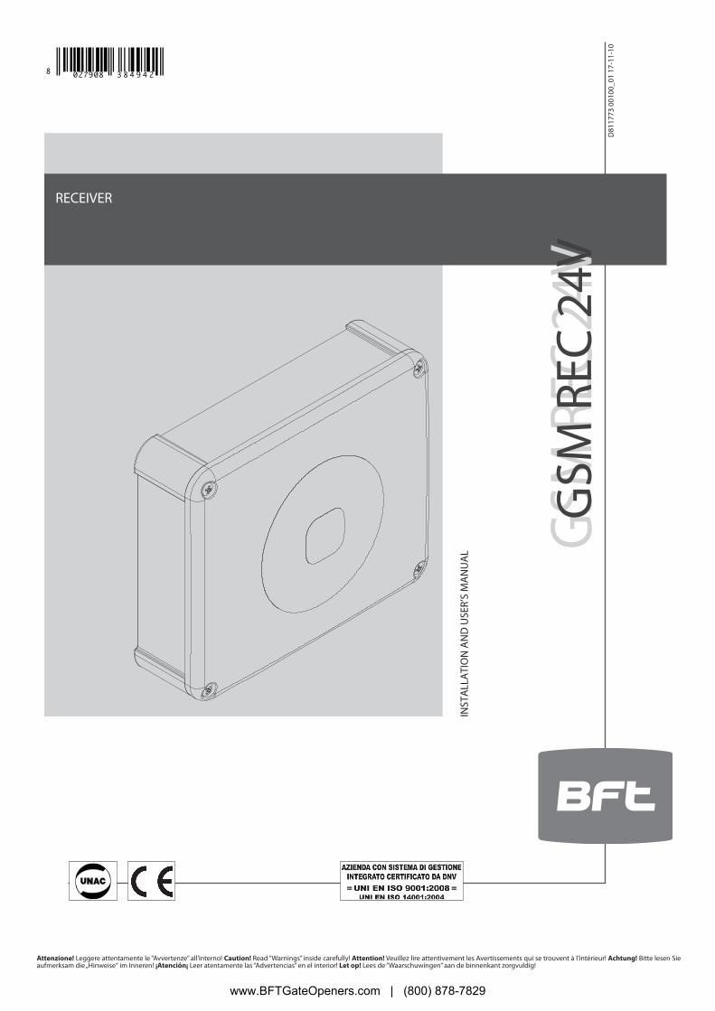
CABLE ARRANGEMENT
DIMENSIONS
PUNCHING OUT KNOCKOUT HOLES
TERMINAL STRIP WIRING
-QUICK INSTALLATION-
2 - GSM RIC 24 V
D81
1773
001
00_0
1
www.BFTGateOpeners.com | (800) 878-7829
ENG
LISH
E
F G
2
1
34
5
SW1
SMS
NO PIN
SIMnumber
H1 2
I
J
4321 87654321 8765
c
J9
43
OU
T2-NC
OU
T2-NO
COM
OU
T 2
MAX 24V 1A 12V / 24V
4321 8
OU
T2-NC
OU
T2-NO
COM OUT2
MAX 1A
87
GN
D
12V+-
6
SW1
/
1234554321
1234554321
1234554321
1234554321
#PWD123456#WHL01=0123456789
INSERTING THE SIM CARD
ADDING A NEW NUMBER TO SIM CARD/
CONFIGURAZIONE OUT 2 / OUT 2 CONFIGURATION / CONFIGURATION OUT 2KONFIGURIERUNG OUT 2 / CONFIGURACIÓN OUT 2 / CONFIGURATIE OUT 2
D81
1773
001
00_0
1
www.BFTGateOpeners.com | (800) 878-7829
WARNING! Important safety instructions. Carefully read and comply with all the warnings and instructions that come with the product as incorrect installation can cause injury to people and animals and damage to property. The warnings and instructions give important information regarding safety, installation, use and maintenance. Keep hold of instructions so that you can attach them to the technical file and keep them handy for future reference.This product has been designed and built solely for the purpose indicated herein. Uses other than those indicated herein might cause damage to the product and create a hazard.The Manufacturer of this product (hereinafter referred to as the “Firm”) disclaims all responsibility resulting from improper use or any use other than that for which the product has been designed, as indicated herein, as well as for failure to apply Good Practice in the construction of entry systems (doors, gates, etc.) and for deformation that could occur during use.Installation must be carried out by qualified personnel (professional installer, according to EN 12635), in compliance with Good Practice and current code.Before commencing installation, check the product for damage.Make sure the stated temperature range is compatible with the site in which the automated system is due to be installed.Do not install this product in an explosive atmosphere: the presence of flammable fumes or gas constitutes a serious safety hazard.Disconnect the electricity supply before performing any work on the system. Also disconnect buffer batteries, if any are connected.Only use original spare parts for any maintenance or repair work. The Firm disclaims all responsibility for the correct operation and safety of the automated system if parts from other manufacturers are used.Do not make any modifications to the automated system’s components unless explicitly authorized by the Firm.Dispose of packaging materials (plastic, cardboard, polystyrene, etc.) in accordance with the provisions of the laws in force. Keep nylon bags and polystyrene out of reach of children.WARNING! safety extra low voltage wires must be kept physically separate from low voltage wires.Anything that is not explicitly provided for in the installation manual is not allowed. The operator’s proper operation can only be gua-ranteed if the information given is complied with. The Firm shall not be answerable for damage caused by failure to comply with the instructions featured herein. While we will not alter the product’s essential features, the Firm reserves the right, at any time, to make those changes deemed opportune to improve the product from a technical, design or commercial point of view, and will not be required to update this publication accordingly.
INSTALLER WARNINGS
4 - GSM RIC 24 V
D81
1773
001
00_0
1
www.BFTGateOpeners.com | (800) 878-7829
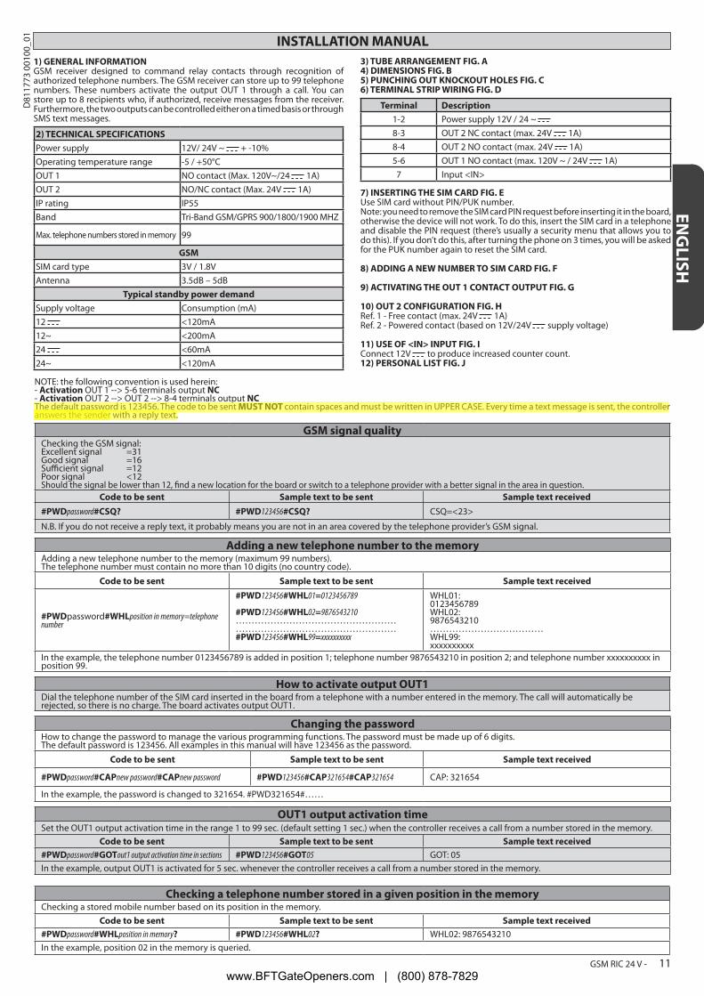
INSTALLATION MANUAL1) GENERAL INFORMATIONGSM receiver designed to command relay contacts through recognition of authorized telephone numbers. The GSM receiver can store up to 99 telephone numbers. These numbers activate the output OUT 1 through a call. You can store up to 8 recipients who, if authorized, receive messages from the receiver. Furthermore, the two outputs can be controlled either on a timed basis or through SMS text messages.
2) TECHNICAL SPECIFICATIONSPower supply 12V/ 24V ~ + -10%Operating temperature range -5 / +50°COUT 1 NO contact (Max. 120V~/24 1A)OUT 2 NO/NC contact (Max. 24V 1A)IP rating IP55Band Tri-Band GSM/GPRS 900/1800/1900 MHZ
Max. telephone numbers stored in memory 99
GSMSIM card type 3V / 1.8VAntenna 3.5dB – 5dB
Typical standby power demandSupply voltage Consumption (mA)12 <120mA12~ <200mA24 <60mA24~ <120mA
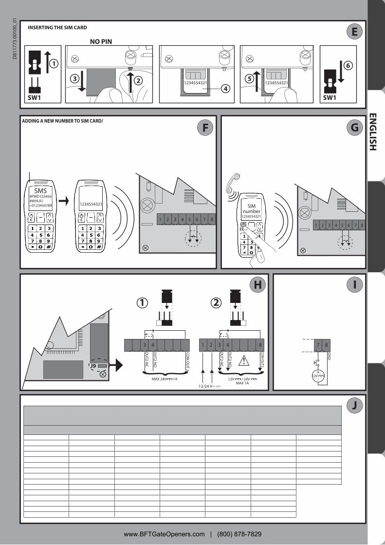
3) TUBE ARRANGEMENT FIG. A4) DIMENSIONS FIG. B5) PUNCHING OUT KNOCKOUT HOLES FIG. C6) TERMINAL STRIP WIRING FIG. D
Terminal Description1-2 Power supply 12V / 24 ~ 8-3 OUT 2 NC contact (max. 24V 1A)8-4 OUT 2 NO contact (max. 24V 1A)5-6 OUT 1 NO contact (max. 120V ~ / 24V 1A)7 Input <IN>
7) INSERTING THE SIM CARD FIG. EUse SIM card without PIN/PUK number.Note: you need to remove the SIM card PIN request before inserting it in the board, otherwise the device will not work. To do this, insert the SIM card in a telephone and disable the PIN request (there’s usually a security menu that allows you to do this). If you don’t do this, after turning the phone on 3 times, you will be asked for the PUK number again to reset the SIM card.
8) ADDING A NEW NUMBER TO SIM CARD FIG. F
9) ACTIVATING THE OUT 1 CONTACT OUTPUT FIG. G
10) OUT 2 CONFIGURATION FIG. HRef. 1 - Free contact (max. 24V 1A)Ref. 2 - Powered contact (based on 12V/24V supply voltage)
11) USE OF <IN> INPUT FIG. IConnect 12V to produce increased counter count.12) PERSONAL LIST FIG. J
NOTE: the following convention is used herein:- Activation OUT 1 --> 5-6 terminals output NC- Activation OUT 2 --> OUT 2 --> 8-4 terminals output NCThe default password is 123456. The code to be sent MUST NOT contain spaces and must be written in UPPER CASE. Every time a text message is sent, the controller answers the sender with a reply text.
GSM signal qualityChecking the GSM signal:Excellent signal =31Good signal =16Sufficient signal =12Poor signal <12 Should the signal be lower than 12, find a new location for the board or switch to a telephone provider with a better signal in the area in question.
Code to be sent Sample text to be sent Sample text received#PWDpassword#CSQ? #PWD123456#CSQ? CSQ=<23>
N.B. If you do not receive a reply text, it probably means you are not in an area covered by the telephone provider’s GSM signal.
Adding a new telephone number to the memoryAdding a new telephone number to the memory (maximum 99 numbers). The telephone number must contain no more than 10 digits (no country code).
Code to be sent Sample text to be sent Sample text received
#PWDpassword#WHLposition in memory=telephone number
#PWD123456#WHL01=0123456789
#PWD123456#WHL02=9876543210…………………………………………………………………………………………#PWD123456#WHL99=xxxxxxxxxx
WHL01:0123456789WHL02:9876543210………………………………WHL99:xxxxxxxxxx
In the example, the telephone number 0123456789 is added in position 1; telephone number 9876543210 in position 2; and telephone number xxxxxxxxxx in position 99.
How to activate output OUT1Dial the telephone number of the SIM card inserted in the board from a telephone with a number entered in the memory. The call will automatically be rejected, so there is no charge. The board activates output OUT1.
Changing the passwordHow to change the password to manage the various programming functions. The password must be made up of 6 digits.The default password is 123456. All examples in this manual will have 123456 as the password.
Code to be sent Sample text to be sent Sample text received
#PWDpassword#CAPnew password#CAPnew password #PWD123456#CAP321654#CAP321654 CAP: 321654
In the example, the password is changed to 321654. #PWD321654#……
OUT1 output activation timeSet the OUT1 output activation time in the range 1 to 99 sec. (default setting 1 sec.) when the controller receives a call from a number stored in the memory.
Code to be sent Sample text to be sent Sample text received#PWDpassword#GOTout1 output activation time in sections #PWD123456#GOT05 GOT: 05In the example, output OUT1 is activated for 5 sec. whenever the controller receives a call from a number stored in the memory.
Checking a telephone number stored in a given position in the memoryChecking a stored mobile number based on its position in the memory.
Code to be sent Sample text to be sent Sample text received#PWDpassword#WHLposition in memory? #PWD123456#WHL02? WHL02: 9876543210In the example, position 02 in the memory is queried.
ENG
LISH
GSM RIC 24 V - 11
D81
1773
001
00_0
1
www.BFTGateOpeners.com | (800) 878-7829
INSTALLATION MANUAL
Deleting a number stored in the memoryTo delete a telephone number stored in the memory.
Code to be sent Sample text to be sent Sample text received#PWDpassword#WHLposition in memoryD #PWD123456#WHL02D WHL02-OKIn the example, the telephone number stored in position 02 in the memory is deleted.
NB: to delete the number stored in position 99, send a text message like the one in the example:#PWD123456#WHL99D=0000000000
Deleting all numbers stored in the memoryAll telephone numbers stored in the memory are deleted.
Code to be sent Sample text to be sent Sample text received#PWDpassword#WHL99D #PWD123456#WHL99D DELALL-OK
Access modeFree access. Access is granted to all telephone numbers that call, even those not stored in the memory
Code to be sent Sample text to be sent Sample text received#PWDpassword#ACM0 (zero) #PWD123456#ACM0 ACM-OFF
Controlled access (default setting). Access is granted only to telephone numbers that are stored in the memory.Code to be sent Sample text to be sent Sample text received
#PWDpassword#ACM2 #PWD123456#ACM2 ACM-ON
Advanced functions
Enabling advanced functionsTo enable input <IN> counter. To enable sending of messages.1=ON0=OFF (default setting)
Code to be sent Sample text to be sent Sample text received#PWDpassword#CTR=on off #PWD123456#CTR=1 CTR=<1>In the example, the input <IN> counter and sending of messages are enabled.
Adding recipients to receive messagesAdding new recipients to the memory who, if authorized, will receive messages from the controller based on whichever functions are enabled below. (from 1 to 8)
Code to be sent Sample text to be sent Sample text received
#PWDpassword#TELrecipient position number=telephone number programmed for receiving messages
#PWD123456#TEL1=9876543210……………………………………………..#PWD123456#TEL6=xxxxxxxxxx
TEL1:9876543210
TEL6:xxxxxxxxxx
In the example, the telephone number 9876543210 is added in position 1 and xxxxxxxxxx in position 6.
Message recipient list queryLists all telephone numbers stored in the memory authorized to receive messages.
Code to be sent Sample text to be sent Sample text received
#PWDpassword#TEL? #PWD123456#TEL?
TEL1:9876543210………........TEL8:xxxxxxxxxxEND
Authorizing recipients to receive messagesThe command to be sent is made up of 8 digits: 1=ON 0=OFF
Code to be sent Sample text to be sent Sample text received
#PWDpassword#RERN=on off on off #PWD123456#RERN=10011000 RERN:10011000
In the example, the numbers stored in positions 1, 4 and 5 are authorized to receive messages.
Checking recipients to receive messages Checks which recipients are authorized to receive messages.
Code to be sent Sample text to be sent Sample text received#PWDpassword#RER? #PWD123456#RER? RERN:
10011000In the example, the numbers stored in positions 1, 4 and 5 are authorized to receive messages.
12 - GSM RIC 24 V
D81
1773
001
00_0
1
www.BFTGateOpeners.com | (800) 878-7829
INSTALLATION MANUAL
Warning message when <IN> contact is closedSet the message that will be sent to authorized recipients in the memory when <IN> contact is closed.The message must be no more than 100 characters long. Only use letters and numbers abc/ABC/123; do not use special characters (&, %,*, etc.).
Code to be sent Sample text to be sent Sample text received
#PWDpassword#STR=message text #PWD123456#STR=Gate closed String:Gate closed
The message that will be sent is: GATE CLOSED.
Warning message when <IN> contact is openedSet the message that will be sent to authorized recipients in the memory when <IN> contact is opened.The message must be no more than 100 characters long. Only use letters and numbers abc/ABC/123; do not use special characters (&, %,*, etc.).
Code to be sent Sample text to be sent Sample text received
#PWDpassword#STO=message text #PWD123456#STO=Gate open String:Gate open
The message that will be sent is: GATE OPEN.
Setting input <IN> partial counterSet the number of times the <IN> contact is closed after which, or after multiples of which, a warning message is sent to authorized recipients.Min. 1Max. 65535Default setting 500The command to be sent is made up of 5 digits:
Code to be sent Sample text to be sent Sample text received#PWDpassword#COA=number of times contact must be closed before message is sent #PWD123456#COA=00005 COA=00005
In the example, message sending has been set to the 5th, 10th, 15th time etc. the <IN> contact is closed.
Setting advanced functionsFunction 1: (default setting)
The board counts the number of times input <IN> changes state. - Every time the contact is closed.The board sends the warning message when the counter reaches the value set by command #COA.-
Function 2:The board counts the number of times input <IN> changes state. - Every time the contact is closed.Output OUT2 is activated when input <IN> first changes state. - See #RLOP function for instructions on de-energizing the relay.The board sends the warning message when the counter reaches the value set by command #COA.-
Function 3:The board counts the number of times input <IN> changes state. - Every time the contact is closed.Output OUT2 is activated when input <IN> first changes state. - See #RLOP function for instructions on de-energizing the relay.The board sends the- #STR warning message every time input <IN> is closed. The board sends the warning message when the counter reaches the value set by command #COA.-
Function 4:The board counts the number of times input <IN> changes state. - Every time the contact is closed.Output OUT 2 is activated for 1 sec. every time input <IN> is closed.-The board sends the warning message when the counter reaches the value set by command #COA.-
Function 5:The board sends the - #STR warning message every time input <IN> is closed.
Function 6:The board sends the- #STR warning message every time input <IN> is closed.The board sends the - #STO warning message every time input <IN> is opened.
Code to be sent Sample text to be sent Sample text received#PWDpassword#CTC=function number #PWD123456#CTC=4 CTC=<4>Function 4 is enabled in the example.
Checking the total number of times input <IN> has changed stateChecks the total number of times input <IN> has changed state. The number increases every time the contact is closed.
Code to be sent Sample text to be sent Sample text received
#PWDpassword#COU? #PWD123456#COU? INC:00143
In the example, the total number of times the input has changed state is 143.
Checking the partial number of times input <IN> has changed state Checks the partial number of times input <IN> has changed state. The number increases every time the contact is closed and is reset when the value reaches the value set in #COA.
Code to be sent Sample text to be sent Sample text received
#PWDpassword#COT? #PWD123456#COT? INC:00004
In the example, the partial number of times the input has changed state is 4.
Counter resetBoth the total and partial counters are reset to 0.
Code to be sent Sample text to be sent Sample text received#PWDpassword#CLA #PWD123456#CLA RECO-OK
GSM RIC 24 V - 13
D81
1773
001
00_0
1
www.BFTGateOpeners.com | (800) 878-7829
MANUAL MODE:Activation of outputs OUT1 and OUT2 for a given time
Outputs OUT1 and/or OUT2 are activated for a settable time. The outputs are independent.Min. 1 sec., Max. 65535 sec. Out1=1, Out2=2The command to be sent to indicate the number of seconds is made up of 5 digits:
Code to be sent Sample text to be sent Sample text received#PWDpassword#RLYoutput to be activated=length of time output stays active in seconds. #PWD123456#RLY2=5400 RLY2=05400
In the example, output 2 stays active for 1 and a half hours.
Checking output stateDisplays the seconds remaining, since relays were activated.
Code to be sent Sample text to be sent Sample text received
#PWDpassword#RLY? #PWD123456#RLY?RLY1:00000RLY2:04800
In the example, output 2 stays active for another 1 hour 20 minutes.
Activating/deactivating outputs OUT1 and OUT2The outputs are activated or deactivated. The outputs are independent.Out1=1, Out2=21=ON; 0=OFF
Code to be sent Sample text to be sent Sample text received#PWDpassword#RLOPoutput to be activated=command #PWD123456#RLOP2=1 RLOP2-ONIn the example, output OUT2 is activated.
TIMED MODESpecial output functions
Function 0: (default setting)Normally deactivated outputs. Special functions are disabled. Normal mode. -
Function 1:Normally activated outputs. Every time a call is made from telephone numbers stored in the memory, output OUT1 is deactivated for 10 sec. and, -after 30 seconds, output OUT2 is deactivated for 5 sec.
Function 2:Normally activated outputs. Programming deactivation of outputs based on time of day. Calls from telephone numbers stored in the memory are -disregarded.
Code to be sent Sample text to be sent Sample text received#PWDpassword#FTRY=function number #PWD123456#FTRY=2 FTRY=<2>Function 2 is enabled in the example
Programming deactivation of outputs OUT1 and OUT2 based on time of dayDetermines at what time individual outputs are deactivated and for how long.8 times can be programmed. SS,MM,HH,TTT,G,R; BE CAREFUL TO GET THE COMMAS AND SEMI-COLON IN THE RIGHT PLACE.
Code to be sent Sample text to be sent Sample text received#PWDpassword#SMW=seconds,minutes,hour,output deactivation time in seconds,number of times programmed,relay programmed;
#PWD123456#SMW=00,48,18,015,1,2; SMW:00,48,18,015,1,2
In the example, output OUT2 is deactivated at 18:48:00 for 15 sec.
Internal clock setSet time in 24-hour formatSS,MM,HH,TTT,G,R; BE CAREFUL TO GET THE COMMAS AND SEMI-COLON IN THE RIGHT PLACE.
Code to be sent Sample text to be sent Sample text received#PWDpassword#TSET=seconds,minutes,hour; #PWD123456#TSET=00,30,08; TIME:00,30,08In the example, the clock is set to 08:30:00.
--------------------------------------------------------------------------------------------------------------------------------------------------Board reset
Restores the controller’s factory settings.N.B. the telephone numbers stored in the memory are not deleted.
Code to be sent Sample text to be sent Sample text received*REST#password *REST#123456 REST-OK
Checking software and hardware version
Code to be sent Sample text to be sent Sample text received#PWDpassword#EDI? #PWD123456#EDI? <WT-009_LIA>2009/8/08/10:45HW:1.0SW:1.0MW:2.3>
INSTALLATION MANUAL
14 - GSM RIC 24 V
D81
1773
001
00_0
1
www.BFTGateOpeners.com | (800) 878-7829


![DERIVATO INTERNO FB01094M04 CITOFONICO - …static.came.com/doc/FB01094M04.pdf · Avvertenze generali • Leggere attentamente le istruzioni, ... [Riassunto] La schermata contiene](https://img.pdfslide.us/doc/110x75/5c6ad46f09d3f27a7e8d45ff/derivato-interno-fb01094m04-citofonico-avvertenze-generali-leggere-attentamente.jpg)