Embed Size (px)
Citation preview
r
March 20, 1995
Mr. Jose Luis Gutierrez Environmental Engineer U.S. Environmental Protection Agency 75 Hawthorne Street San Francisco, California 94105-3901
Subject: Supplemental Work Plan Number 1 for the Underground Injection Control Permit Application, Florence, Arizona
Dear Mr. Gutierrez:
c
AQUIFER PROTECTION PROGRAM SECTION
MAR 2 71995
RECEIVED
15-1899/05
Magma is pleased to submit the Supplemental Work Plan Number 1 for the Underground Injection Control (UIC) Pel1llit Application Work Plan. Supplemental Work Plan Number 1 describes the procedures necessary and sufficient to fulfill the formation testing requirements for the Florence Project. This supplemental work plan describes the data collection procedures proposed for the collection of additional data required for a Class III UIC permit. These procedures were also presented in Appendices G and H of the Aquifer Protection Permit (APP) Application Work Plan dated February 2, 1995.
If you have any questions, please do not hesitate to contact me or Mr. Steve Mellon of Brown and Caldwell (602) 222-4444.
Very truly yours
MAGMA COPPER COMPANY
John Kline Environmental Manager
JK:cl Enclosure
cc: Ms . Shirin Tolle, Arizona Department of Environmental Quality
7400 North Oracle Road, Suite 200, Tucson, Arizona 85704 (602) 575-5600 • FAX (602) 575-5639
SWVP-000765
SUPPLEMENTAL WORK PLAN NUMBER 1 Underground Injection Control Permit Application Work Plan
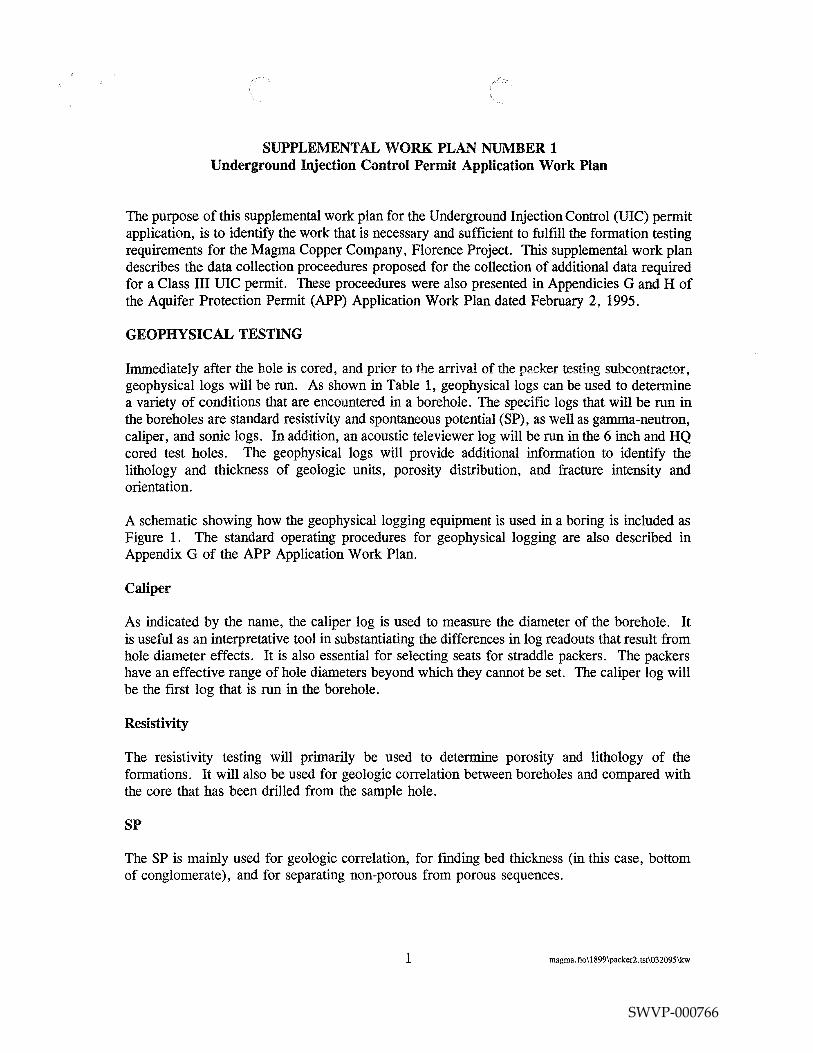
The purpose of this supplemental work plan for the Underground Injection Control (UIC) permit application, is to identify the work that is necessary and sufficient to fulfill the formation testing requirements for the Magma Copper Company, Florence Project. This supplemental work plan describes the data collection proceedures proposed for the collection of additional data required for a Class III UIC permit. These proceedures were also presented in Appendicies G and H of the Aquifer Protection Permit (APP) Application Work Plan dated February 2, 1995.
GEOPHYSICAL TESTING
Immediately after the hole is cored, and prior to the arrival of the packer testing subcontractor, geophysical logs will be run. As shown in Table 1, geophysical logs can be used to determine a variety of conditions that are encountered in a borehole. The specific logs that will be run in the boreholes are standard resistivity and spontaneous potential (SP), as well as gamma-neutron, caliper, and sonic logs. In addition, an acoustic televiewer log will be run in the 6 inch and HQ cored test holes. The geophysical logs will provide additional information to identify the lithology and thickness of geologic units, porosity distribution, and fracture intensity and orientation.
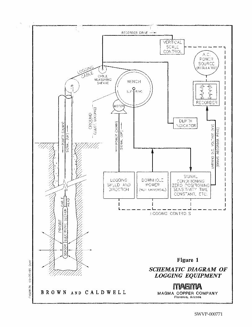
A schematic showing how the geophysical logging equipment is used in a boring is included as Figure 1. The standard operating procedures for geophysical logging are also described in Appendix G of the APP Application Work Plan.
Caliper
As indicated by the name, the caliper log is used to measure the diameter of the borehole. It is useful as an interpretative tool in substantiating the differences in log readouts that result from hole diameter effects. It is also essential for selecting seats for straddle packers. The packers have an effective range of hole diameters beyond which they cannot be set. The caliper log will be the frrst log that is run in the borehole.
Resistivity
The resistivity testing will primarily be used to determine porosity and lithology of the formations. It will also be used for geologic correlation between boreholes and compared with the core that has been drilled from the sample hole.
SP
The SP is mainly used for geologic correlation, for fmding bed thickness (in this case, bottom of conglomerate), and for separating non-porous from porous sequences.
1 magma. flo \1899\packer2. tst\032095\kw
SWVP-000766
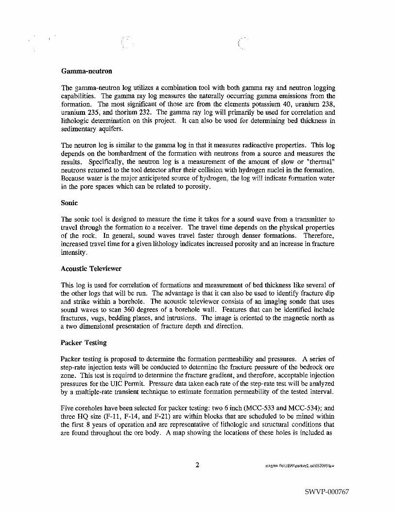
Gamma-neutron
The gamma-neutron log utilizes a combination tool with both gamma ray and neutron logging capabilities. The gamma ray log measures the naturally occurring gamma emissions from the formation. The most significant of those are from the elements potassium 40, uranium 238, uranium 235, and thorium 232. The gamma ray log will primarily be used for correlation and lithologic determination on this project. It can also be used for determining bed thickness in sedimentary aquifers.
The neutron log is similar to the gamma log in that it measures radioactive properties. This log depends on the bombardment of the formation with neutrons from a source and measures the results. Specifically, the neutron log is a measurement of the amount of slow or "thermal" neutrons returned to the tool detector after their collision with hydrogen nuclei in the formation. Because water is the maJor anticipated source of hydrogen, the log will indicate formation water in the pore spaces which can be related to porosity.
Sonic
The sonic tool is designed to measure the time it takes for a sound wave from a transmitter to travel through the formation to a receiver. The travel time depends on the physical properties of the rock. In general, sound waves travel faster through denser formations. Therefore, increased travel time for a given lithology indicates increased porosity and an increase in fracture intensity.
Acoustic Televiewer
This log is used for correlation of formations and measurement of bed thickness like several of the other logs that will be run. The advantage is that it can also be used to identify fracture dip and strike within a borehole. The acoustic televiewer consists of an imaging sonde that uses sound waves to scan 360 degrees of a borehole wall. Features that can be identified include fractures, vugs, bedding planes, and intrusions. The image is oriented to the magnetic north as a two dimensional presentation of fracture depth and direction.
Packer Testing
Packer testing is proposed to determine the formation permeability and pressures. A series of step-rate injection tests will be conducted to determine the fracture pressure of the bedrock ore zone. This test is required to determine the fracture gradient, and therefore, acceptable injection pressures for the UIC Permit. Pressure data taken each rate of the step-rate test will be analyzed by a multiple-rate transient technique to estimate formation permeability of the tested interval.
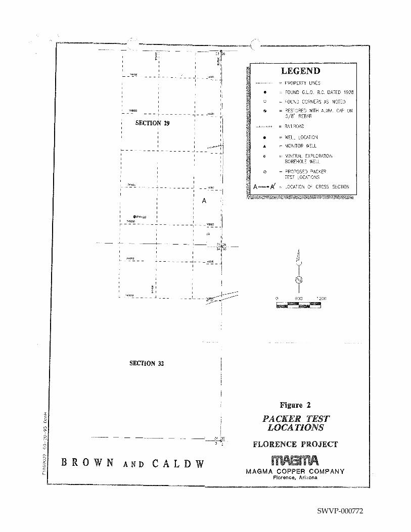
Five coreholes have been selected for packer testing: two 6 inch (MCC-533 and MCC-534); and three HQ size (F-11, F-14, and F-21) are within blocks that are scheduled to be mined within the first 8 years of operation and are representative of lithologic and structural conditions that are found throughout the ore body. A map showing the locations of these holes is included as
2 magma. flo\ 1899\packer2. tst\032095\kw
SWVP-000767
Figure 2. The holes range in depth from 950 to 1,400 feet. At this time, the exact positioning of the packers within the borehole and the number of tests in each borehole has not been determined.
Approach
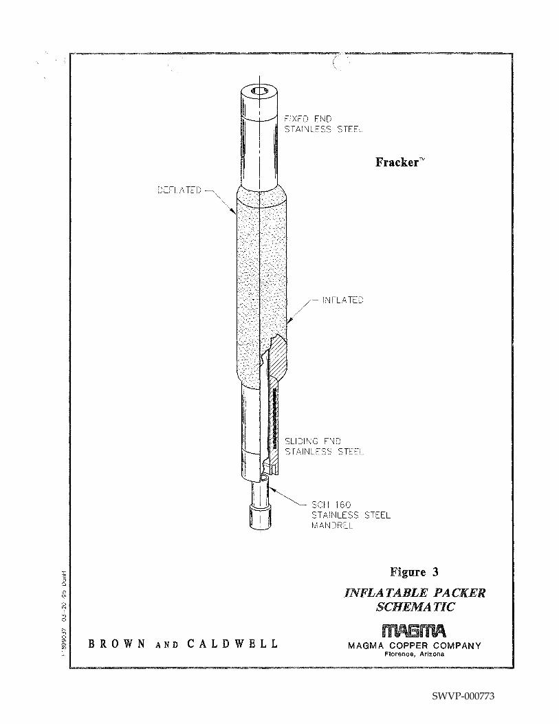
After the logging is completed, the hole will be purged of drilling fluid and pumped until clean formation water is obtained. The step-rate injection test will consist of injecting fluid (formation water) into a specific interval at a series of increasing rates, with each rate lasting the same length of time. It is anticipated that five to seven rates, lasting 15 to 20 minutes per each rate and volumes of 1 to 10 gallons per minute will be required to sufficiently determine fracture opening pressures of the formation. A schematic of the testing apparatus is found as Figure 3.
The analysis of the data consists of plotting injection pressure at the end of each step versus injection rate. This eliminates friction effects. Bottom hole pressures will also be plotted. Generally, the plot will have two straight line segments with a break in the line indicating fracture pressure.
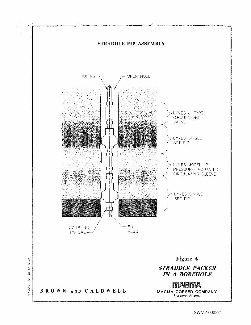
The step-injection tests will be conducted utilizing a straddle packer assembly with a standing valve pressure transducer. Figure 4 shows a diagram of the straddle packer assembly. The standing valve transducer will enable monitoring of real-time bottom-hole pressures. In addition, permeability testing will be conducted concurrently with the fracture pressure testing.
Test Procedures
The procedures for conducting the tests will be as follows:
1. Crew arrives on site and lays out all equipment to be used.
2. Sound the corehole to verify the available total depth and ensure that there are no obstructions. Measure water level in the hole at this time.
3. Pull out and inspect the packers to check for any damage that may have occurred during shipping. The inflation line is attached using a quick coupler, the connection is tested, and the inflation tubing is taped to the high pressure pipe that will be used to hang the packer.
4. Install the straddle packer with the standing valve seat in the drill rod or tubing to the depth desired. For this project, the first depth will be at the bottom of the borehole. The formation will be tested on the way up to gain the best fracture gradient. At this time, the electric wireline unit (to run the standing valve and pressure gauge) and lubricator (surface pressure control head) are installed. Additionally, the water and air supply lines are hooked up to the booster pump, compressor, and valve tree recording devices.
3 magma. flo\ !899\packer2. tst\032095\kw
SWVP-000768
5. The packers are inflated and deflated several times to make certain that they are seating and deflating properly. The operator will monitor the solution pressure at the bottom of the hole until it is stabilized.
6. Once the operator is satisfied that the system is operating well, the hydraulic pressure pump is started and slowly brought up to pressure.
7. Initiate injection and increase rate/pressure to achieve fracture opening.
8. Seat standing valve to achieve downhole shut-in pressure, instantaneous shut-in pressure and pressure fall-off.
9. Release surface pressure.
10. Repeat injection and pressure recording steps for three or four cycles.
11. Pull out of hole with wireline.
12. Release pressure on the packer to allow the packer to be moved to the next location for testing where the testing procedure will be repeated. The highest elevation for formation pressure testing will be 30 feet below the top of the oxide zone.
Transducers and flow meters will be calibrated in accordance with the manufacturers' specifications and standards provided with each instrument. The anticipated accuracy is 1 percent. The standard operating procedures for packer testing are also described in Appendix H of the APP Application Work Plan dated February 2, 1995.
REFERENCE
1. Matthews, C. S. and Russell, D. G.: Pressure Buildup and Flow Tests in Wells, Monograph Series, Society of Petroleum Engineers of AIME, Dallas (1967) 1, Chap. 8.
4 magma. flo\!899\packer2.tst\032095\kw
SWVP-000769
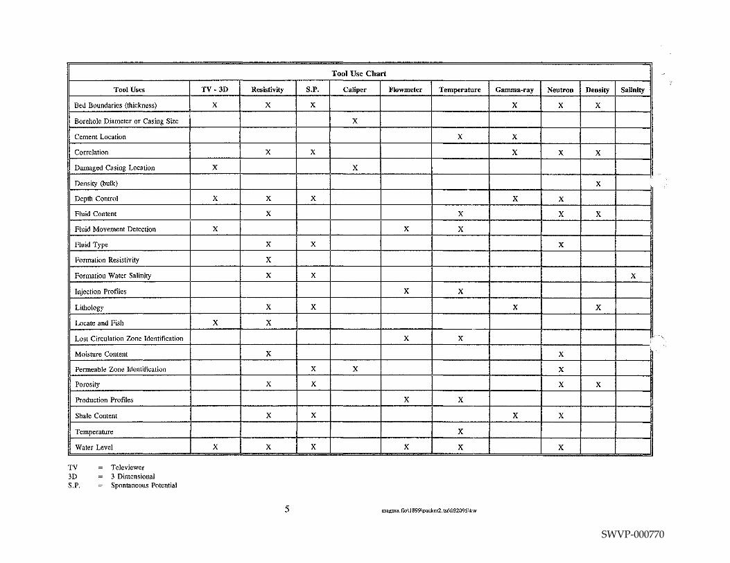
Tool Use Chart
Tool Uses TV-3D Resistivity S.P. Caliper Flowmeter Temperature Gamma-ray Neutron Density Salinity
Bed Boundaries (thickness) X X X X X X
Borehole Diameter or Casing Size X
Cement Location X X
Correlation X X X X X
Damaged Casing Location X X
Density (bulk) X
Depth Control X X X X X
Fluid Content X X X X
Fluid Movement Detection X X X
Fluid Type X X X
Formation Resistivity X
Formation Water Salinity X X X
Injection Profiles X X
Lithology X X X X
Locate and Fish X X
Lost Circulation Zone Identification X X 1"""",,
Moisture Content X X
Permeable Zone Identification X X X
Porosity X X X X
Production Profiles X X
Shale Content X X X X
Temperature X
Water Level X X X X X X
TV Televiewer 3D 3 Dimensional S.P. Spontaneous Potential
5 magma. flo\ 1899\packer2. tst\032095\kw
SWVP-000770
I c 0
0
<{) (J)
I 0 N I
n 0
({)
n 0 (J) (J)
ro u..
IS z
0(3 z0 =:>S 0. O:::f-0~
_J
w "--"'
RECORDER DRIVE -
VERTICAL SCALE -- - - - - - ,
CONTROL
WENCH
SLIP RING
~ l 0 0,---., '--"'a.. 0:: ::::J W'-" ;: _J
0 <( Q_ z
l ~
LOGGING SPEED AND DIRECTION
RECORDER
DEPTH INDICATOR
SIGNAL DOWNHOLE CONDITIONING
POWER ZERO POSITIONING (NOT UNIVERSAL) SENSITIVITY TIME
CONSTANT, ETC.
> 68
z w w (_) Q_
;:: 0:: _J w §? ~
0 0 ~ Cl 0::
(_) (f)
z 5 >= 0:: 0:: Cl
5
l------L------~------~ LOGGING CONTROLS
Figure 1
SCHEMATIC DIAGRAM OF LOGGING EQUIPMENT
BROWN AND CALDWELL MAGMA COPPER COMPANY Florance, Arizona
SWVP-000771
I c 0
0
t{) 0> I
0 N I
n 0
BROWN
I
27,26
~I ~,
! __ ,._~
I
I
-- l-I
I I '3000 ! ------,--- --~
I
'I I, I
'I I ! 748CO.J I JBOOQ ! -----~--y-------~--~-
1 SECTION 29 I
I I
l---------+--------.1-- ----1-
1 I I
L -'~""'- - - - L - - - - - - -: - - - -6000 +I I 1
A 'I I
l 7.15C(l() ! '45000 r-------T-------~---
1 f2
I
I
'--:·_ --::27~6=---341 35
I I I ! \i ~ _7~ - - - - 4 - - - - - - - -1- - - ::~ - ~ I I I I 1 I I
I I I I I
~I I ;!;I
L -'~ - - - - J - - - - - __ : ___ ~
I
SECTION 32
_J 3 2
AND CALDW
• 0
•
e
0
LEGEND = PROPERTY LINES
FOUND G.L.D B.C. DATED 1928
FOUND CORNERS AS NOTED
RESTORED WITH ALUM. CAP ON 5/8" REBAR
RAILROAD
= WELL LOCATION
= MONITOR WELL
MINERAL EXPLORATION BOREHOLE WELL
PROPOSED PACKER TEST LOCATIONS
A--/{ = LOCATION OF CROSS SECTION
0 600 1200
Figure 2
PACKER TEST LOCATIONS
FLORENCE PROJECT
MAGMA COPPER COMPANY Florence, Arizona
SWVP-000772
:r: c 0
0
C[) (J)
I 0 N I ,.,
0
BROWN AND CALDWELL
FIXED END STAINLESS STEEL
INFLATED
SLIDING END STAINLESS STEEL
Fracker™
SCH 160 STAINLESS STEEL MANDREL
Figure 3
INFLATABLE PACKER SCHEMATIC
MAGMA COPPER COMPANY Florence, Arizona
SWVP-000773
I c 0
0
t[) m I
0 N I
n 0
<:0 n 0 m m <:0
"-
STRADDLE PIP ASSEMBLY
TUBING
,, ' . . .~ ' . :
. ~ ' ; ..
COUPLING, TYPICAL
L OPEN HOLE
BULL PLUG
BROWN AND CALDWELL
LYNES J- TYPE CIRCULATING VALVE
LYNES SINGLE SET PIP
} LYNES MODEL "p" PRESSURE-ACTUATED CIRCULATING SLEEVE
LYNES SINGLE SET PIP
Figure 4
STRADDLE PACKER IN A BOREHOLE
MAGMA COPPER COMPANY Florence, Arizona
SWVP-000774