Embed Size (px)
Citation preview
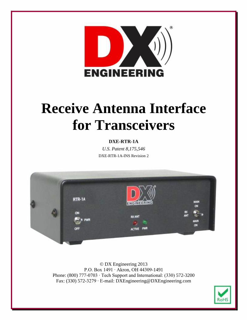
Receive Antenna Interface
for Transceivers
DXE-RTR-1A
U.S. Patent 8,175,546
DXE-RTR-1A-INS Revision 2
© DX Engineering 2013
P.O. Box 1491 ∙ Akron, OH 44309-1491
Phone: (800) 777-0703 ∙ Tech Support and International: (330) 572-3200
Fax: (330) 572-3279 ∙ E-mail: [email protected]
2
Table of Contents Introduction 3
“An Amateur Radio Dilemma” 3
The DX Engineering Solution 4
Features 4
General Information 5
DXE-RTR-1A Receive Antenna Interface for Transceivers - Front Panel 8
DXE-RTR-1A Receive Antenna Interface for Transceivers - Rear Panel 9
Transmit Ground Line Function and Troubleshooting 11
Receive Antenna Input Limiter 12
Internal Jumpers 12
Connection Descriptions 12
Receiving Antenna Spacing Guidelines 14
Typical System Configurations 14
Diagram 1A - Active Receive Antenna and Transmit Antenna 17
Diagram 1B - Active Receive Antenna and Transmit Antenna with RX IN/OUT 18
Diagram 2 - Active Receive Antenna and Transmit Antenna using High Power 19
Additional System Configurations 20
Diagram 3 - DXE-NCC-1 Receive Antenna Variable Phasing Controller
with two Active Receive Antennas 22
Diagram 4 -
DXE-NCC-1 Receive Antenna Variable Phasing Controller with two
Active Receive Antennas using high power to the transmit antenna. 23
Diagram 5 - Single Transmit Antenna System using a DXE-RPA-1 Preamplifier 24
Diagram 6 - Single Transmit Antenna System using a DXE-RBS-1 Reversible Beverage
Antenna System 25
Diagram 7 - Single Transmit Antenna with a DXE-RFS-TS2P Receive Four
Square Array Package 26
Diagram 8 -
One Monoband or Multi-band Vertical Transmit Antenna using a
DXE-ARAV2-1P Active Receive Antenna using the DXE-NCC-1 Receive
Antenna Variable Phasing Controller
27
Diagram 9 - Classic T/R relay connections for separate Transmitter and Receiver with
a Single Transmit Antenna System using a DXE-RPA-1 Preamplifier 28
Diagram 10 -
Relay connections for separate Transceiver and Receiver with a Single
Transmit Antenna System using a DXE-RSC-2 Two-Port
Splitter/Combiner
29
Diagram 11 - Relay connections for separate Transceiver and Receiver with an Active
Receive Antenna and a Single Transmit Antenna System using a DXE-
RSC-2 Two-Port Splitter/Combiner
30
Operation 31
Manual Updates 31
Optional Items 32
Technical Support 36
Warranty 36
3
Introduction
The patented* DXE-RTR-1A Receive Antenna Interface for Transceivers is a unique and simple,
multi-purpose relay unit which automatically switches the RF output antenna connector on any HF
transceiver between a receiving antenna system and a standard transmitting antenna. A manual
override switch allows instantaneous switching between transmit and receive antennas. The RTR-
1A Receive Transmit Relay system operates from a "Transmit on Ground" keying line.
Designed specifically for HF transceivers which do not have a receive antenna input, the DXE-
RTR-1A enables operators to safely enjoy the improved reception of a low noise receiving antenna
system. This shielded relay system provides a safe method of connecting a receive antenna, such as
a Beverage, Active Receive system, or other receiving accessories to your radio. The RTR-1A
features a patented* receive antenna limiter circuit, with an RF limiting threshold at approximately
two volts peak. that pass as normal level signals without affecting receiver IMD.
The RTR-1A is useful device for many applications, including:
Connection of external receiving antennas to transceivers lacking external antenna ports
T-R antenna switch for older equipment using separate transmitters and receivers
Interfacing antennas to phasing or noise cancelling systems
Addition of a Receive Preamplifier
Excellent failsafe receiver protection for close-spaced antennas without the performance
degradation of typical cheap back-to-back diode circuits
(* U.S. Patent Number: 8,175,546)
“An Amateur Radio Dilemma”
The benefits of using separate receiving antennas for “low-band” HF operations have been known
for many years. Enthusiasts of operations below 14 MHz have learned that typical transmitting
antennas collect too much noise for reception, especially for DXing on the 160 and 80 meter bands.
Unfortunately, for over three decades, only the most expensive HF transceivers have been
manufactured with a separate receive antenna input. Even so, many older and newer “high-end”
radios do not provide for switching their reception between a receive antenna and the default
transmit antenna, nor do they interrupt the receive input during transmit. To obtain a separate
receive antenna input, certain models required optional equipment or modules which are no longer
available.
For many Amateur Radio Operators, the joy of low-noise, low-band reception with a separate
receive antenna has been out of reach. Modern, “affordable” HF transceivers have been designed
without any provision for a receive antenna connection. Otherwise very capable transceivers, even
brand new models, lack a built-in receive antenna port and relay system.
4
The DX Engineering Solution
The DXE-RTR-1A Receive Antenna Interface for Transceivers, offers a special antenna switching
solution, that incorporates safeguards against accidental RF transmission into a receive antenna
system. The DXE-RTR-1A may be used for switching flexibility and to protect the receiver input
during transmit for those transceivers that are so equipped.
Typical homebrew and commercial transmit/receive (T/R) relays, and other receive switching
solutions on the market, offer little or no protection to the receive antenna equipment. Transmitted
energy could damage receiving equipment if keying and timing errors or power loss occurs.
The DXE-RTR-1A is a new HF relay system that allows reception only if the unit is powered and
the keying line from the transceiver is connected. As soon as the transceiver is keyed or the DXE-
RTR-1A loses power at any time, the RF output from the transceiver is automatically diverted to
the transmit antenna connection. A very fast acting (about 4 ms) 200 watt RF capable relay in the
DXE-RTR-1A diverts the transceiver output quickly enough for QSK operation (full break-in CW)
while listening to a receive antenna. The DXE-RTR-1A also allows instantaneous receive
comparisons between the receive antenna and the transmit antenna, with a convenient three-position
front panel switch. Indicator LEDs (Light Emitting Diodes) on the front panel allow the user to
determine at a glance if the unit is properly powered and if the receive or transmit antenna is
selected for reception and when the unit is keyed for transmission.
Features Attractive, Heavy Stainless Steel Enclosure that won't slide on your desk
Front Panel LED Status Indicators and Manual Override Switch
200 Watt Transmit Switching Capability
Supports CW full break in (QSK)
Receive Antenna Inputs and Outputs use RCA phono and Type F connectors for safety
Main Antenna and Radio Connectors are SO-239 for ease of installation
Safe switching - automatically connects radio to transmit antenna when dc power is off
Hot switching lockout – disconnects receive antenna during transmit mode
Adds protection and antenna switching flexibility - for transceivers with receive ports
Level Limiter helps to protect receiver front end from overload due to strong received
signals
RoHS compliant assembly
The DXE-RTR-1A Receive Antenna Interface for Transceivers is an attractive station accessory,
housed in a heavy, stainless-steel enclosure which matches other DX Engineering station
accessories. Cable connections to the DXE-RTR-1A are made entirely on the back panel, and all
switches and indicators are on the front panel, for a clean, easy-to-use installation.
5
General Information
The DXE-RTR-1A Receive Antenna Interface for Transceivers is the accessory that allows owners
of transceivers which lack a receive antenna input to safely enjoy optional receive enhancing
equipment. The DX Engineering DXE-RPA-1 Receive Pre-Amplifier may be used in-line on a
receive antenna. The DXE-NCC-1 Receive Antenna Variable Phasing Unit and the DXE-AAPS3-
1P Active Antenna Phasing System are now available for operations for RX ANT Input deprived
radios. The DXE-RTR-1A may be combined with the DXE-TVSU-1A Time Variable Sequence
Unit for high power operations at stations where the receive antenna is physically close to the
transmit antenna and for status indication of keying.
Old and new transceivers alike can benefit from the use of a high performance, low-noise pre-
amplifier to enhance reception. The DXE-RPA-1 Receive Pre-Amplifier offers dynamic range and
third order intercept performance that exceeds most top dollar transceivers. As requested by many
Amateurs worldwide, the receive only DXE-RPA-1 Receive Pre-Amplifier may now be used in-
line safely for improved reception with a transmitting antenna, when connected with the DXE-
RTR-1A.
For enthusiasts who wish to use a favorite transceiver as a receiver only, now using an RF output
connection to a receive pre-amplifier and antenna and can be virtually worry free. Accidental
transmission through the receive antenna or receive pre-amplifier need not cause concern with a
properly connected DXE-RTR-1A.
Many owners of transceivers that have receive ports are choosing to use the DXE-RTR-1A. For these
operators it offers three benefits. First and foremost, the DXE-RTR-1A can protect the front end of
the transceiver with automatic disconnection of the receive input during transmit, preserving fast CW
break-in operation (QSK) with a 4 ms response time. Second, the DXE-RTR-1A offers a simple and
handy way to toggle between listening to receive and transmit antennas with a front panel switch.
Third, the DXE-RTR-1A has a built-in Level Limiter circuit to help protect your receiver from
damage due to strong received signals.
Most high-end transceivers, old and new, offer a receive antenna input that DOES NOT interrupt
RF or switch off during transmit, even though the receiver is muted, very quickly in full break-in
CW operation. This is a design feature which allows an operator to listen to a receive antenna,
located a sufficient distance away from the transmit antenna to prevent receiver front end damage,
allowing very fast QSK operations. However, most Amateurs who own this type of radio do not
have access to the real estate for the required antenna separation to support this type of operation.
Unfortunately, several hams have discovered these facts the hard way, after unintentionally blowing
the front end of their expensive transceiver with transmitted RF riding in on their receive antenna
feedline. Also, on many transceivers, connection of a receive antenna to the RX (antenna) IN port
requires removal of the “RX OUT to RX IN” jumper patch cable, and then the transmit antenna
cannot be heard. Recommendations for external relays and other devices have not addressed the
need for protection as well as switching options. The DXE-RTR-1A fills this need with an
attractive and versatile accessory.
6
For those who want to use a separate receiver or use a second transceiver as a receiver and interrupt
the receive antenna feedline when transmitting, the DXE-RTR-1A may be used as a T/R relay.
Also, monitoring the transmitting antenna with a second receiver while operating the main
transceiver with a receive antenna (SO2R application) is possible with the DXE-RTR-1A.
The DXE-RTR-1A may also be used with an optional DXE-RSC-2 Two-Port Splitter/Combiner to
share a transmit antenna between two transceivers, with only one used for transmitting, or between
a transceiver and a receiver.
Standard relays and coaxial relays that are used in a typical default receive T/R system are prone to
keying timing problems which can result in damaging receiver front-ends due to pulses or hot
switching. The DXE-RTR-1A solves that problem for vintage radio collectors and operators. Used
as a traditional T/R relay, it switches a transmit antenna between a receiver and a transmitter with
an output of up to 200 watts. The DXE-RTR-1A offers complete protection and high speed (4 ms)
receive to transmit transfer. The DXE-RTR-1A is a superior solution to old, slow T/R relays, and it
allows the safe use of an optional receive preamplifier.
Detailed diagrams of the following applications and accessory connections are included in this
manual.
Connecting a transceiver that does not have a receive antenna input to:
DXE-ARAV3-1P Active Receive Antenna
DXE-ARAV3-1P Active Receive Antenna and transmit Antenna using high power
DXE-NCC-1 Receive Antenna Variable Phasing Controller with two DXE-ARAV3-1P
Active Receive Antennas
DXE-NCC-1 Receive Antenna Variable Phasing Controller with two DXE-ARAV3-1P
Active Receive antennas using high power to the transmit antenna.
Single transmit antenna system using a DXE-RPA-1 Preamplifier
Single transmit antenna system using a DXE-RBS-1 Reversible Beverage Antenna System
Single transmit antenna with a DXE-RFS-TS2P Receive Four Square Array Package
One DX Engineering Monoband or Multi-band Vertical transmit antenna using a DXE-
ARAV3-1P Active Receive Antenna with the DXE-NCC-1 Receive Antenna Variable
Phasing Controller
Connecting a transceiver that has a receive antenna input and receive output:
For any receive antenna system interruption of receive antenna feedline during transmit
For the versatility of switching between listening to either the receive or transmit antenna
Connecting a transmitter and receiver to the same antenna system:
Classic T/R relay connections for separate Transmitter and Receiver with a Single Transmit
Antenna System using a DXE-RPA-1 Preamplifier
Connecting two transceivers, one used for receive only, to the same transmit antenna, for
simultaneous reception.
Using an optional DXE-RSC-2 Two-Port Splitter/Combiner, a transmit antenna can be
shared for dual receiving.
7
Connecting two transceivers, one used for receive only, to the same active receive antenna, for
simultaneous reception.
Using an optional DXE-RSC-2 Two-Port Splitter/Combiner, a transmit antenna can be
shared for dual receiving.
Other uses of the DXE-RTR-1A are possible but not detailed in this manual:
Connecting a non-active receive only antenna to a transceiver and transmitting antenna
system
Connecting a main transceiver and a second transceiver for single operator-two radio
(SO2R) contesting.
Given the nature of Amateur Radio Operators and their interest in experimentation, there may be
many other options available when using the DXE-RTR-1A Receive Antenna Interface for
Transceivers.
8
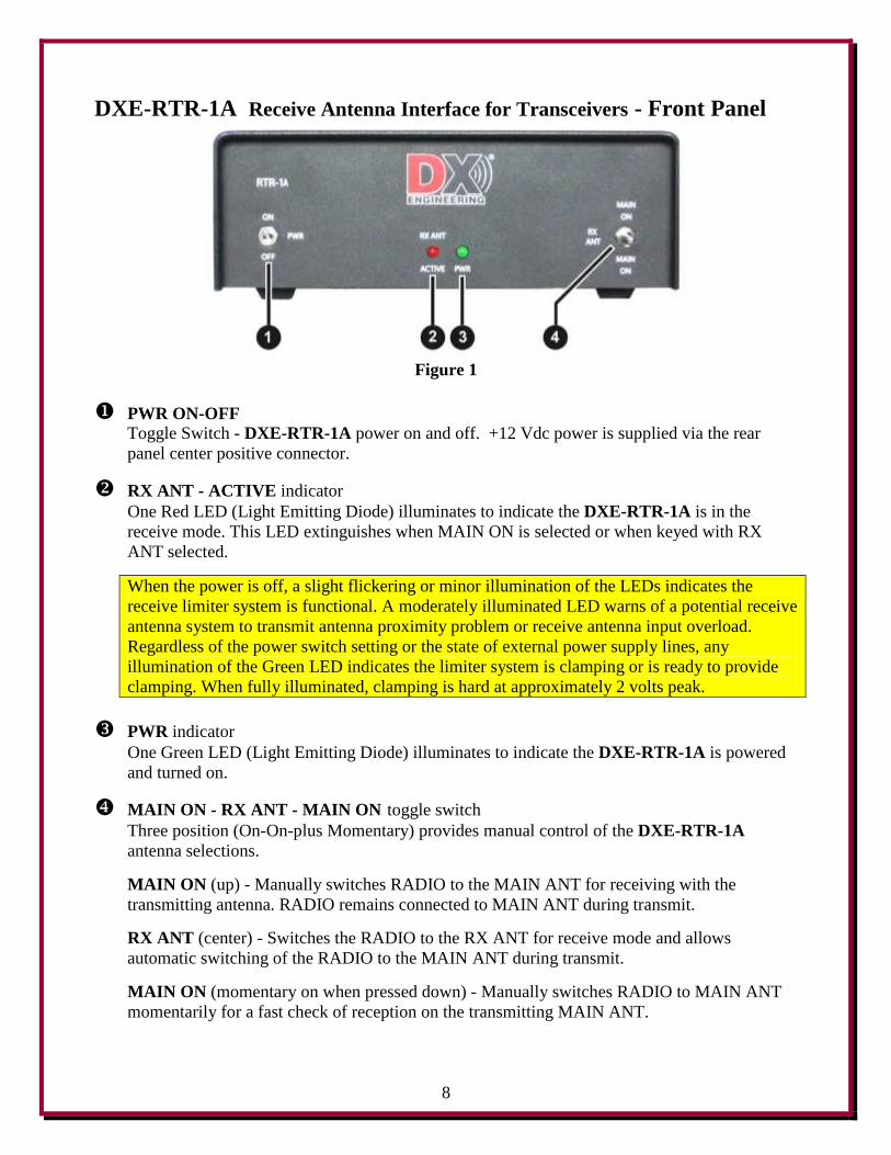
DXE-RTR-1A Receive Antenna Interface for Transceivers - Front Panel
Figure 1
PWR ON-OFF Toggle Switch - DXE-RTR-1A power on and off. +12 Vdc power is supplied via the rear
panel center positive connector.
RX ANT - ACTIVE indicator
One Red LED (Light Emitting Diode) illuminates to indicate the DXE-RTR-1A is in the
receive mode. This LED extinguishes when MAIN ON is selected or when keyed with RX
ANT selected.
When the power is off, a slight flickering or minor illumination of the LEDs indicates the
receive limiter system is functional. A moderately illuminated LED warns of a potential receive
antenna system to transmit antenna proximity problem or receive antenna input overload.
Regardless of the power switch setting or the state of external power supply lines, any
illumination of the Green LED indicates the limiter system is clamping or is ready to provide
clamping. When fully illuminated, clamping is hard at approximately 2 volts peak.
PWR indicator
One Green LED (Light Emitting Diode) illuminates to indicate the DXE-RTR-1A is powered
and turned on.
MAIN ON - RX ANT - MAIN ON toggle switch
Three position (On-On-plus Momentary) provides manual control of the DXE-RTR-1A
antenna selections.
MAIN ON (up) - Manually switches RADIO to the MAIN ANT for receiving with the
transmitting antenna. RADIO remains connected to MAIN ANT during transmit.
RX ANT (center) - Switches the RADIO to the RX ANT for receive mode and allows
automatic switching of the RADIO to the MAIN ANT during transmit.
MAIN ON (momentary on when pressed down) - Manually switches RADIO to MAIN ANT
momentarily for a fast check of reception on the transmitting MAIN ANT.
9
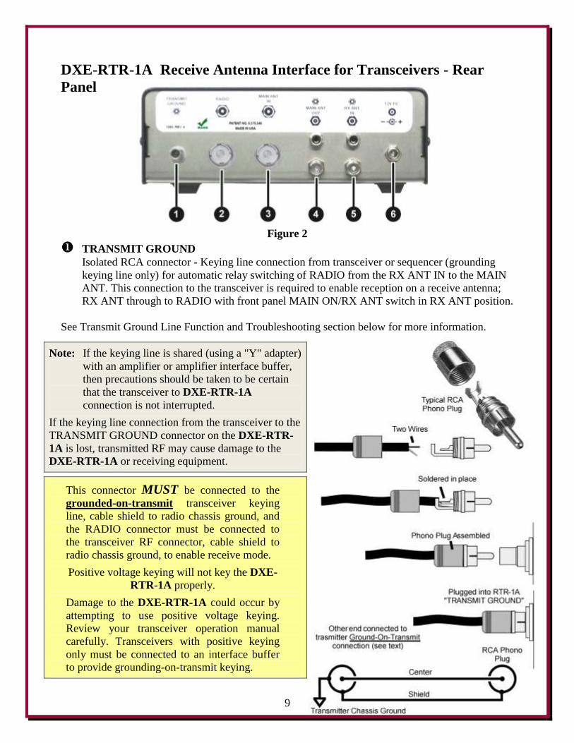
DXE-RTR-1A Receive Antenna Interface for Transceivers - Rear
Panel
Figure 2
TRANSMIT GROUND
Isolated RCA connector - Keying line connection from transceiver or sequencer (grounding
keying line only) for automatic relay switching of RADIO from the RX ANT IN to the MAIN
ANT. This connection to the transceiver is required to enable reception on a receive antenna;
RX ANT through to RADIO with front panel MAIN ON/RX ANT switch in RX ANT position.
See Transmit Ground Line Function and Troubleshooting section below for more information.
Note: If the keying line is shared (using a "Y" adapter)
with an amplifier or amplifier interface buffer,
then precautions should be taken to be certain
that the transceiver to DXE-RTR-1A
connection is not interrupted.
If the keying line connection from the transceiver to the
TRANSMIT GROUND connector on the DXE-RTR-
1A is lost, transmitted RF may cause damage to the
DXE-RTR-1A or receiving equipment.
This connector MUST be connected to the
grounded-on-transmit transceiver keying
line, cable shield to radio chassis ground, and
the RADIO connector must be connected to
the transceiver RF connector, cable shield to
radio chassis ground, to enable receive mode.
Positive voltage keying will not key the DXE-
RTR-1A properly.
Damage to the DXE-RTR-1A could occur by
attempting to use positive voltage keying.
Review your transceiver operation manual
carefully. Transceivers with positive keying
only must be connected to an interface buffer
to provide grounding-on-transmit keying.
10
RADIO
SO-239 connector - Transmit and receive RF connection to the transceiver or connection to
transmitter RF connector. Maximum 200 Watts transmit with MAIN ANT connected to a
suitable antenna or load. Connected, by default, to the MAIN ANT IN connector when the
DXE-RTR-1A is not powered or the MAIN ANT/RX ANT switch in the MAIN ANT position.
MAIN ANT IN
SO-239 connector - RF connection to a suitable transmit antenna or load. Connected, by
default, to the RADIO connector when the DXE-RTR-1A is not powered or the MAIN
ANT/RX ANT switch in the MAIN ANT position. Connection for high end transceiver "RX
OUT" to monitor transmit antenna through DXE-RTR-1A. Details in Diagram 1B and text. While compatible with high power amateur radio stations, the RTR-1A can never be connected
to the output of a high power amplifier. The MAIN ANT IN port must always connect to the
input of any external amplifier or directly to the transmitting antenna system path if no
amplifier is in use.
MAIN ANT OUT RCA type connector and F-Connector (in parallel) - Output for special applications, receive
only connection of MAIN ANT during receive mode only. Used for transmit antenna
monitoring and pre-amplification or phasing purposes only. Disconnected during transmit or
when unit is switched to MAIN ANT. This port is not level limited. This port is active only in
the RX ANT receive mode, when power is applied and the “RX ANT ACTIVE” Red LED is
fully illuminated. See Diagrams 5 and 8.
RX ANT IN
RCA type connector and F-Connector (in parallel) - Input for receive only antenna, or from a
receive only device. May accept output from a DXE-RPA-1 Receive Preamplifier, or from a
DXE-NCC-1 Receive Antenna Variable Phasing Controller. See Receive Antenna Input
Limiter section below for more information.
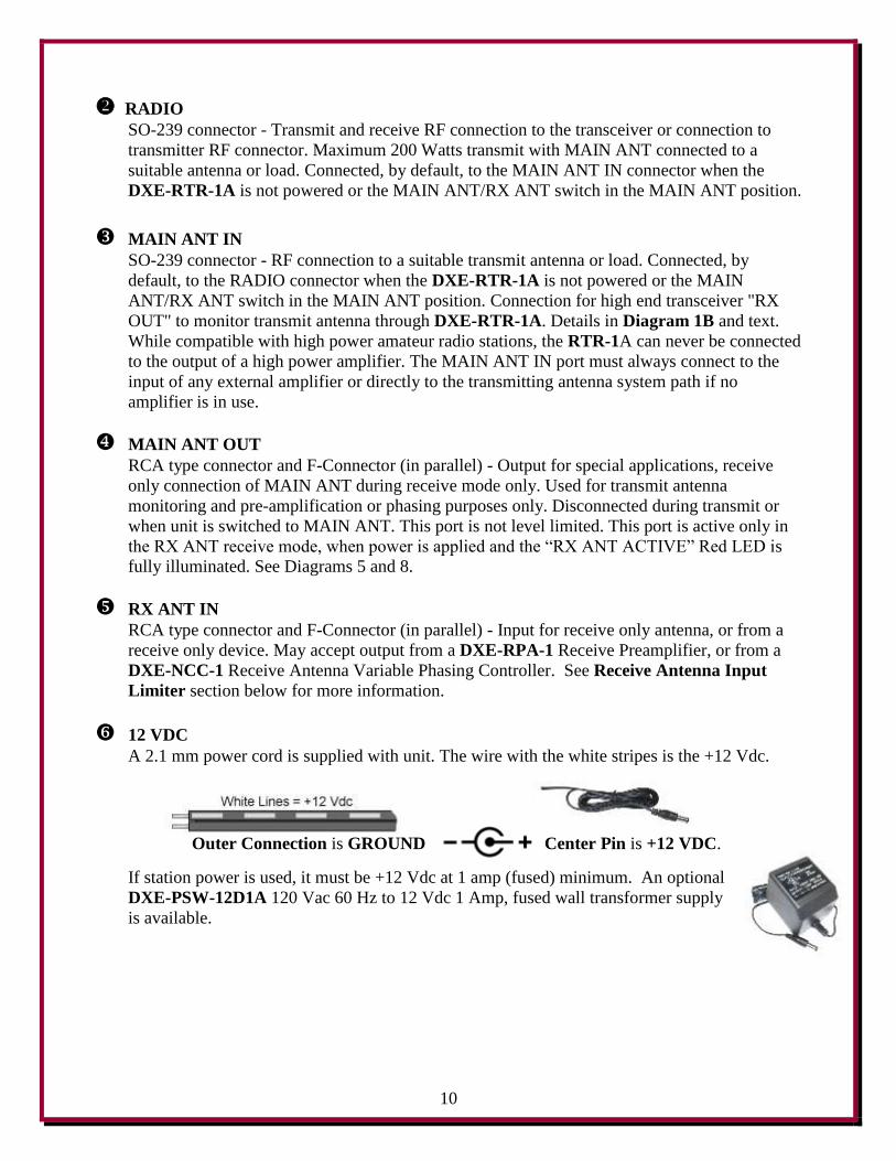
12 VDC
A 2.1 mm power cord is supplied with unit. The wire with the white stripes is the +12 Vdc.
Outer Connection is GROUND Center Pin is +12 VDC.
If station power is used, it must be +12 Vdc at 1 amp (fused) minimum. An optional
DXE-PSW-12D1A 120 Vac 60 Hz to 12 Vdc 1 Amp, fused wall transformer supply
is available.
11
Transmit Ground Line Function and Troubleshooting
The Transmit Ground line sources approximately 5 volts open circuit. It sources approximately 50
microamperes, which is unlikely to affect or damage other external devices. A low voltage
(standard pull-to-ground) is considered "transmit" mode, which disconnects the receive antenna and
restores a transceiver (transmitter) to MAIN ANT connection. A valid Transmit Ground occurs
when the line is pulled below 1.5 volts. The unit will return to receive mode when the line voltage
goes above 3.5 volts. The nominal trigger voltage is TTL logic level, at approximately 2.5 volts.
The Transmit Ground line is protected for reverse positive voltages up to 50 volts.
The Transmit Ground line can often, but not always, be "T" or "Y" connected to other external
devices. Any incompatibility is unavoidable, because any parallel incompatibility is rooted in the
behavior of non-standardized external systems, which are beyond our control.
As shown in RTR-1A Connection Diagrams in this manual, the Ameritron ARB-704 Amplifier
Interface may be connected with a Y-adapter, i.e. paralleled, for connection to the Transmit Ground.
If that unit is connected with a Multi-Port Din cable from the transceiver, the “Radio” connector on
the ARB-704 may be able to be used as the parallel keying connection to Transmit Ground on the
RTR-1A. However, internal jumpers in the ARB-704 may be set in such a way as to prevent proper
operation of the RTR-1A or the ARB-704 when connected in this manner or with a Y-adapter.
Resetting the ARB-704 internal jumpers from 2.5 volts to 5 volts can restore normal operation in
some cases.
If any external device prevents the Transmit Ground line voltage from going over 3 volts positive
on receive, or prevents a low line (transmit state) from going solidly below 1.5 volts, send-receive
switching may become unreliable or unpredictable. The proper test for this is to measure the send
and receive mode voltages at the Transmit Ground jack. External devices can be unplugged in order
to locate which any external device is preventing normal operation of the Transmit Ground line.
If a troublesome external device is in use, operation is generally correctable with the addition of an
external isolation diode, anode to the incompatible external device with cathode towards the
Transmit Ground line. A small rectifier diode, such as a 1N4001-1N4007 rectifier, will work with
most devices. The RTR-1A already contains an internal isolation diode, so there is no reason to use
a diode on the Transmit Ground line.
Some very old equipment supplies 120Vac for external control. In very rare cases, some systems
supply a positive-going send voltage, with zero voltage indicating receive. Such systems are not
compatible with direct connections to the RTR-1A although they can almost always be interfaced
with a few simple external components.
12
Receive Antenna Input Limiter
The Receive Antenna Input port connects directly to an RF voltage limiter. Regardless of any front
panel switch setting and regardless of any power supply system disconnect or failure, this port is
clamped at approximately 2 volts peak RF voltage. When power is on, a unique patented clamping
system provides a hard limiter at 2 volts. Unlike most other systems, this clamp does not affect
signals below 2 volts. Unlike most cheap back-to-back diode limiters, this patented clamp does not
compromise or reduce receiver system IMD performance.
This clamping circuit, unless internal shunts on HD1 and HD2 are located rearward to defeat
clamping, is always operational. Regardless of power switch setting or state of external power
supply lines, any illumination of the Green LED indicates the system is clamping or ready to
provide clamping. When fully illuminated, clamping is hard at approximately 2 volts peak.
The clamping circuit can be damaged with application of sustained average RF currents over 100
mA. The normal failure mode is to short the receive port to ground although that is not absolutely
guaranteed.
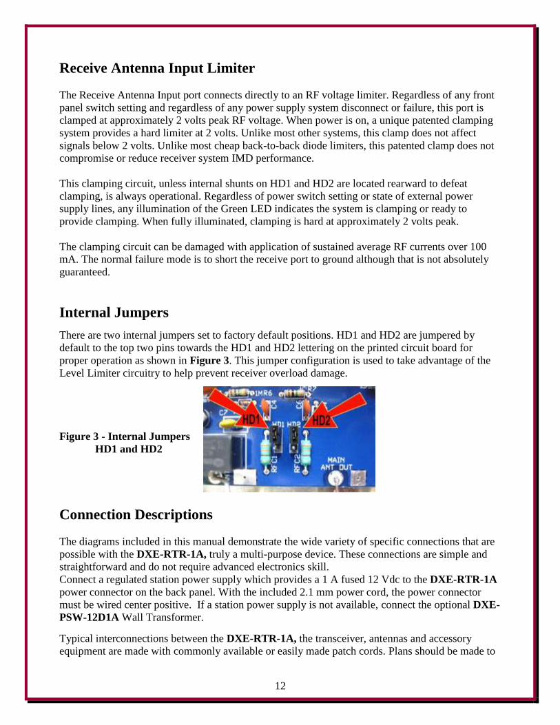
Internal Jumpers
There are two internal jumpers set to factory default positions. HD1 and HD2 are jumpered by
default to the top two pins towards the HD1 and HD2 lettering on the printed circuit board for
proper operation as shown in Figure 3. This jumper configuration is used to take advantage of the
Level Limiter circuitry to help prevent receiver overload damage.
Figure 3 - Internal Jumpers
HD1 and HD2
Connection Descriptions
The diagrams included in this manual demonstrate the wide variety of specific connections that are
possible with the DXE-RTR-1A, truly a multi-purpose device. These connections are simple and
straightforward and do not require advanced electronics skill.
Connect a regulated station power supply which provides a 1 A fused 12 Vdc to the DXE-RTR-1A
power connector on the back panel. With the included 2.1 mm power cord, the power connector
must be wired center positive. If a station power supply is not available, connect the optional DXE-
PSW-12D1A Wall Transformer.
Typical interconnections between the DXE-RTR-1A, the transceiver, antennas and accessory
equipment are made with commonly available or easily made patch cords. Plans should be made to
13
locate the DXE-RTR-1A close to the transceiver, so instant reception antenna changes may be
made with the front panel switch.
Receive only connections must be made with either male RCA phono style patch cords or with male
F connector cables. Custom length cables with F-Connectors installed can be supplied by DX
Engineering. If RCA phono style patch cords are used, high quality connectors should be selected
for this low-noise RF application. Inexpensive audio cables may not be suitable. RCA Phono and F-
Connectors are used on DX Engineering receive devices to help prevent accidental connection to
transmitting connectors.
Transmitting RF connections on the DXE-RTR-1A, from RADIO to the transceiver and from
MAIN ANTENNA to the transmitting antenna system, tuner or amplifier are made with standard
PL-259 patch cables in lengths that permit locating the equipment in their proper operating
positions. Custom length cables with PL-259 connectors installed can be supplied by DX
Engineering.
The TRANSMIT GROUND keying line connection to the DXE-RTR-1A must be made to enable
reception with a connected receive antenna or accessory. Keying line connection from transceiver
or sequencer (grounding keying line only) for automatic relay switching of RADIO from the RX
ANT IN to the to MAIN ANT.
This connection may be shared with an amplifier-transceiver interface buffer keying input. The
diagrams in this manual show connections to transceivers with grounded-on-transmit keying line
only.
Note: If the keying line is shared (using a "Y" adapter) with an amplifier or amplifier interface
buffer, then precautions should be taken to be certain that the transceiver to DXE-RTR-1A
connection is not interrupted.
If the keying line connection from the transceiver to the TRANSMIT GROUND connector on the
DXE-RTR-1A is lost, transmitted RF may cause damage to the DXE-RTR-1A or receiving
equipment.
The TRANSMIT GROUND keying line connector MUST be connected to a grounded-
on-transmit transceiver keying line, cable shield to radio chassis ground, and the RADIO
connector must be connected to the transceiver RF connector, cable shield to radio chassis
ground, to enable receive mode.
Positive voltage keying will not key the DXE-RTR-1A properly.
Damage to the DXE-RTR-1A could occur by attempting to use positive voltage keying.
Review your transceiver operation manual carefully. Transceivers with positive keying
only, must be connected to an interface buffer to provide grounding-on-transmit keying.
14
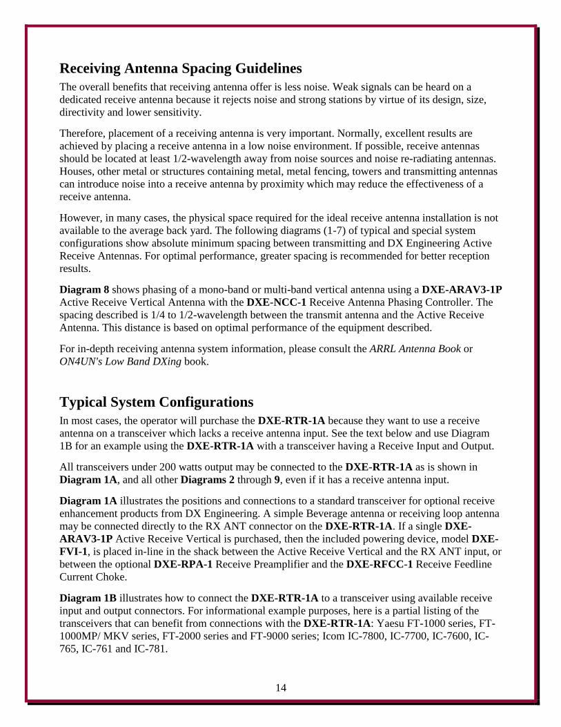
Receiving Antenna Spacing Guidelines
The overall benefits that receiving antenna offer is less noise. Weak signals can be heard on a
dedicated receive antenna because it rejects noise and strong stations by virtue of its design, size,
directivity and lower sensitivity.
Therefore, placement of a receiving antenna is very important. Normally, excellent results are
achieved by placing a receive antenna in a low noise environment. If possible, receive antennas
should be located at least 1/2-wavelength away from noise sources and noise re-radiating antennas.
Houses, other metal or structures containing metal, metal fencing, towers and transmitting antennas
can introduce noise into a receive antenna by proximity which may reduce the effectiveness of a
receive antenna.
However, in many cases, the physical space required for the ideal receive antenna installation is not
available to the average back yard. The following diagrams (1-7) of typical and special system
configurations show absolute minimum spacing between transmitting and DX Engineering Active
Receive Antennas. For optimal performance, greater spacing is recommended for better reception
results.
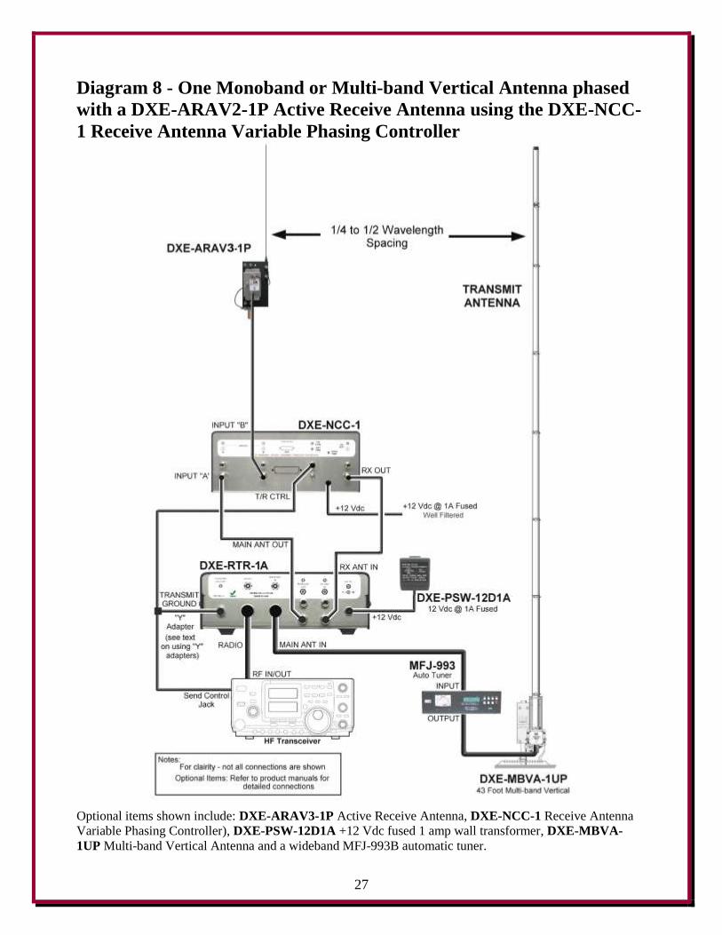
Diagram 8 shows phasing of a mono-band or multi-band vertical antenna using a DXE-ARAV3-1P
Active Receive Vertical Antenna with the DXE-NCC-1 Receive Antenna Phasing Controller. The
spacing described is 1/4 to 1/2-wavelength between the transmit antenna and the Active Receive
Antenna. This distance is based on optimal performance of the equipment described.
For in-depth receiving antenna system information, please consult the ARRL Antenna Book or
ON4UN's Low Band DXing book.
Typical System Configurations
In most cases, the operator will purchase the DXE-RTR-1A because they want to use a receive
antenna on a transceiver which lacks a receive antenna input. See the text below and use Diagram
1B for an example using the DXE-RTR-1A with a transceiver having a Receive Input and Output.
All transceivers under 200 watts output may be connected to the DXE-RTR-1A as is shown in
Diagram 1A, and all other Diagrams 2 through 9, even if it has a receive antenna input.
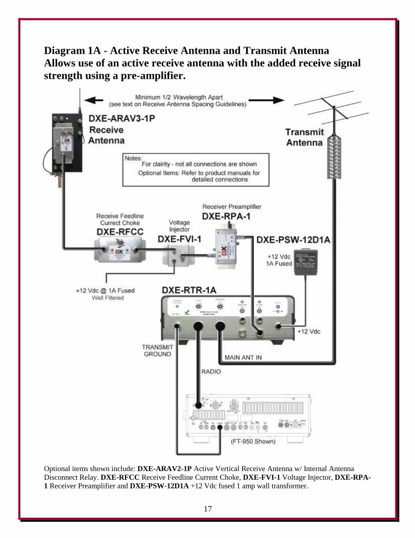
Diagram 1A illustrates the positions and connections to a standard transceiver for optional receive
enhancement products from DX Engineering. A simple Beverage antenna or receiving loop antenna
may be connected directly to the RX ANT connector on the DXE-RTR-1A. If a single DXE-
ARAV3-1P Active Receive Vertical is purchased, then the included powering device, model DXE-
FVI-1, is placed in-line in the shack between the Active Receive Vertical and the RX ANT input, or
between the optional DXE-RPA-1 Receive Preamplifier and the DXE-RFCC-1 Receive Feedline
Current Choke.
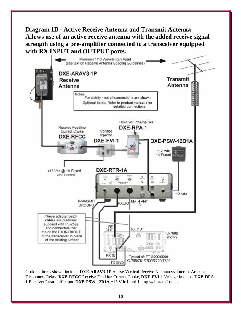
Diagram 1B illustrates how to connect the DXE-RTR-1A to a transceiver using available receive
input and output connectors. For informational example purposes, here is a partial listing of the
transceivers that can benefit from connections with the DXE-RTR-1A: Yaesu FT-1000 series, FT-
1000MP/ MKV series, FT-2000 series and FT-9000 series; Icom IC-7800, IC-7700, IC-7600, IC-
765, IC-761 and IC-781.
15
Most high-end transceivers, old and new, offer a receive antenna input that DOES NOT interrupt or
switch off during transmit even though the receiver is muted. Also, on many transceivers, connection
of a receive antenna to the RX IN port means that the RX OUT to RX IN jumper patch cord must be
removed. Then the transmit antenna cannot be heard. For operators of these high-end transceivers, the
DXE-RTR-1A offers two benefits. First and foremost, it can protect the front end with automatic
disconnection of the receive input, preserving very fast break-in operation (full QSK) with 4 ms
response. Second, the DXE-RTR-1A offers a simple and handy way to toggle between listening to
the receive and transmit antennas with a front panel switch. Third, the DXE-RTR-1A has a built-in
Level Limiter circuit to help protect your receiver from damage due to strong received signals.
The DXE-RTR-1A RX ANT connector is used for the receive antenna system signals. The
transceiver RF output is connected to the transmit antenna or amplifier. The transceiver amplifier
keying line must be connected to the DXE-RTR-1A TRANSMIT GROUND connector to enable
reception of the receive antenna signal. Customer supplied RF patch cords must be used to connect
to the SO-239 RADIO and MAIN ANT IN ports on the DXE-RTR-1A to the RX IN and OUT
ports on a transceiver, respectively, replacing the existing jumper patch cable. In most cases these
are simply two patch cords with PL-259s on one end and male RCA phono plugs on the other end.
This connection will never allow transmitted RF into the front end of the transceiver. Since the RX
OUT carries only the received transmit antenna signals, the DXE-RTR-1A will allow monitoring of
either the receive or transmit antenna as described in this manual. This connection scheme is
applicable for the radios listed above, as well as others not listed, which offer RX IN and OUT. This
transceiver connection scheme may also be adapted for use with any of the diagramed system
configurations. If your transceiver has only a receive antenna input but no RX OUT, use the
standard connection methods depicted in Diagrams 1a and 2 through 9.
Diagram 2 shows a standard transceiver connection arrangement, with the addition of a typical RF
amplifier used on the transceiver output for high power operations. The DXE-RTR-1A and a
keyed-on-ground amplifier may be able to share the same grounding keying line from the
transceiver, but the use of an optional amplifier keying interface buffer is recommended. Do not
share the keying line of the DXE-RTR-1A with an older amplifier that uses high voltage relays.

16
NOTE: The DXE-RTR-1A may never be used on the output of an RF amplifier.
MAXIMUM RF power allowed through the unit is 200 watts.
Note: If the keying line is shared (using a "Y" adapter) with an amplifier or amplifier interface
buffer, then precautions should be taken to be certain that the transceiver to DXE-RTR-1A
connection is not interrupted.
If the keying line connection from the transceiver to the TRANSMIT GROUND connector
on the DXE-RTR-1A is lost, transmitted RF may cause damage to the DXE-RTR-1A or
receiving equipment.
The TRANSMIT GROUND keying line connector MUST be connected to a grounded-on-
transmit transceiver keying line, cable shield to radio chassis ground, and the RADIO
connector must be connected to the transceiver RF connector, cable shield to radio chassis
ground, to enable receive mode.
Positive voltage keying will not key the DXE-RTR-1A properly. Damage to the DXE-RTR-1A
could occur by attempting to use positive voltage keying. Review your transceiver operation
manual carefully. Transceivers with positive keying only must be connected to an interface
buffer to provide grounding-on-transmit keying.
17
Diagram 1A - Active Receive Antenna and Transmit Antenna
Allows use of an active receive antenna with the added receive signal
strength using a pre-amplifier.
Optional items shown include: DXE-ARAV2-1P Active Vertical Receive Antenna w/ Internal Antenna
Disconnect Relay. DXE-RFCC Receive Feedline Current Choke, DXE-FVI-1 Voltage Injector, DXE-RPA-
1 Receiver Preamplifier and DXE-PSW-12D1A +12 Vdc fused 1 amp wall transformer.
18
Diagram 1B - Active Receive Antenna and Transmit Antenna
Allows use of an active receive antenna with the added receive signal
strength using a pre-amplifier connected to a transceiver equipped
with RX INPUT and OUTPUT ports.
Optional items shown include: DXE-ARAV3-1P Active Vertical Receive Antenna w/ Internal Antenna
Disconnect Relay. DXE-RFCC Receive Feedline Current Choke, DXE-FVI-1 Voltage Injector, DXE-RPA-
1 Receiver Preamplifier and DXE-PSW-12D1A +12 Vdc fused 1 amp wall transformer.
19
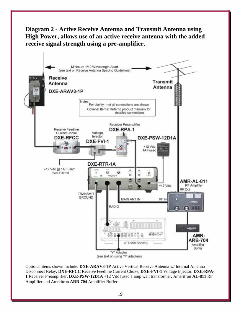
Diagram 2 - Active Receive Antenna and Transmit Antenna using
High Power, allows use of an active receive antenna with the added
receive signal strength using a pre-amplifier.
Optional items shown include: DXE-ARAV3-1P Active Vertical Receive Antenna w/ Internal Antenna
Disconnect Relay, DXE-RFCC Receive Feedline Current Choke, DXE-FVI-1 Voltage Injector, DXE-RPA-
1 Receiver Preamplifier, DXE-PSW-12D1A +12 Vdc fused 1 amp wall transformer, Ameritron AL-811 RF
Amplifier and Ameritron ARB-704 Amplifier Buffer.
20
Additional System Configurations
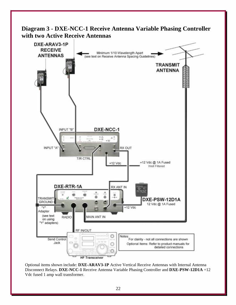
Diagram 3 shows a new receiving application. The DXE-RTR-1A Receive Antenna Interface for
Transceivers now allows owners of transceivers which lack a receive antenna input to use a phased
receive antenna array. This diagram shows the connections for use of the DXE-AAPS3-1P
Electronically Rotatable Receive Antenna System, which consists of two DXE-ARAV3-1P Active
Vertical Receive Antennas with Internal Antenna Disconnect Relays and the DXE-NCC-1 Receive
Antenna Variable Phasing Controller using the DXE-RTR-1A Receive Transmit Relay.
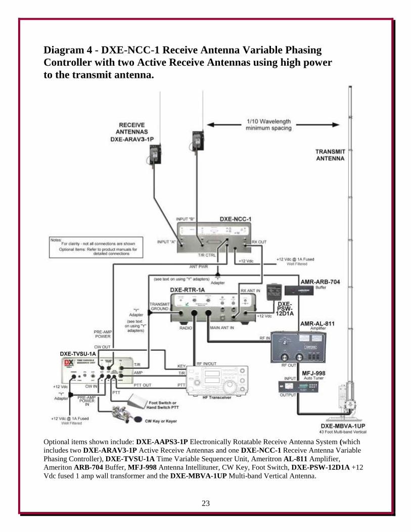
Diagram 4 details the connections to optional equipment required when operating high power and
using the DXE-AAPS3-1P Electronically Rotatable Receive Antenna System. The addition of the
DXE-TVSU-1A Time Variable Sequencer Unit will produce the correct keying of all devices, to
protect the Active Receive Antennas from high power RF damage. The DXE-RTR-1A provides
connection to the transceiver which does not offer a receive antenna input.
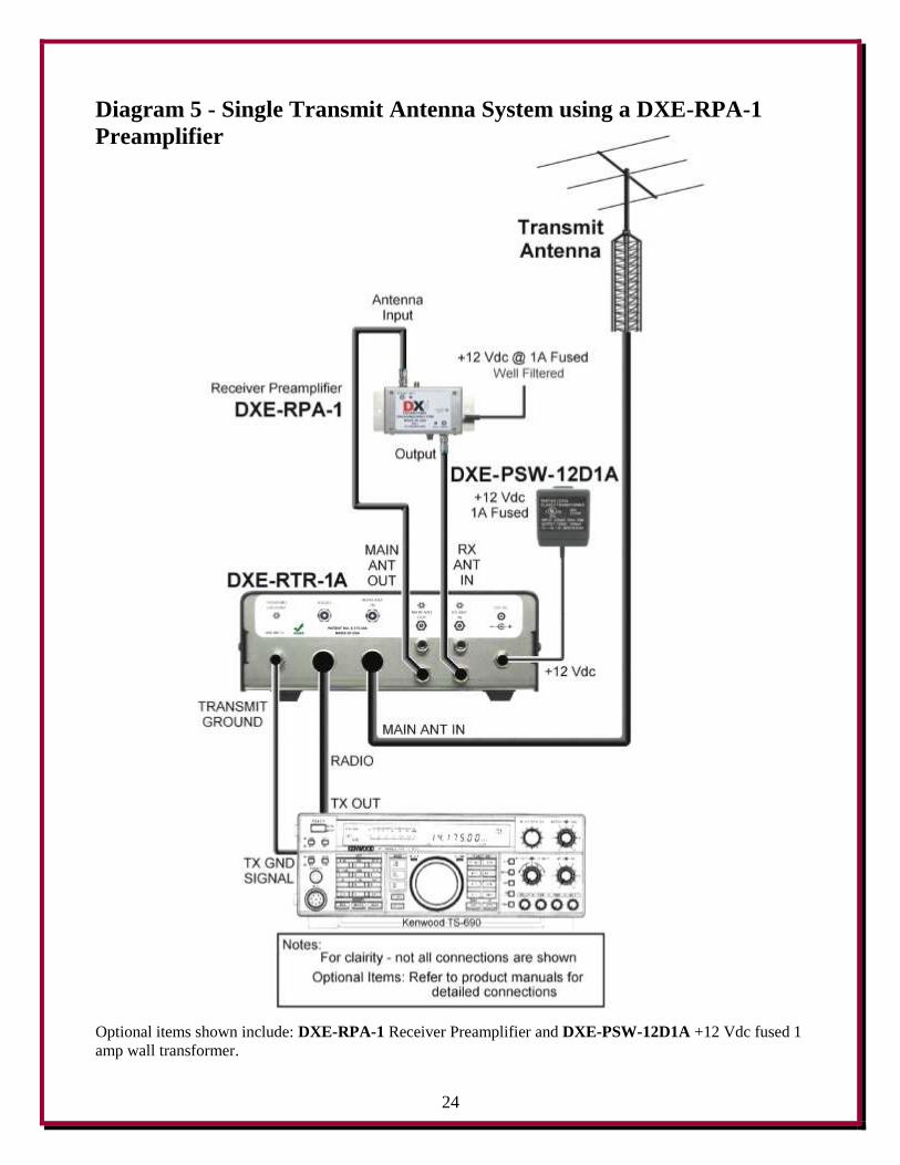
Diagram 5 includes the exceptional DXE-RPA-1 Receive Preamplifier in-line with the main
(transmit) antenna. For many years Amateurs have been requesting a method to employ a receiving
device on their transceivers which lack a built-in preamplifier. The DXE-RTR-1A provides this
connection option. Instantaneous receive comparisons between 'preamplifier in' and 'preamplifier
out' are easily accomplished using the DXE-RTR-1A MAIN ON - RX ANT - MAIN ON toggle
switch.
Receiving with the transmitting antenna on a second transceiver or receiver while operating with the
main transceiver connected to a receive antenna is a common contesting application known as
Single Operator – Two Radios (SO2R). This is now easily accomplished by connecting the MAIN
ANT OUT line to the input of the second radio. Reception with the transmitting antenna is safely
interrupted during main transceiver transmissions.
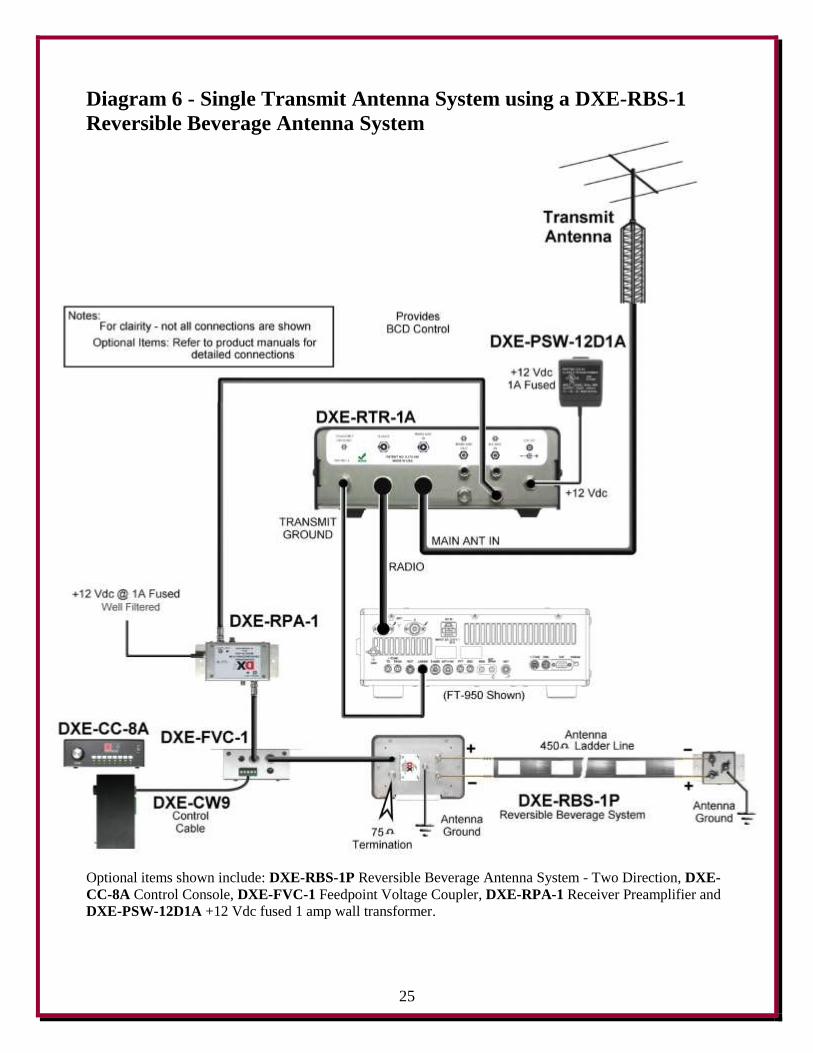
Diagram 6 demonstrates another common use for the DXE-RTR-1A and the connections required
for use of a two direction DXE-RBS-1P Reversible Beverage Antenna System.
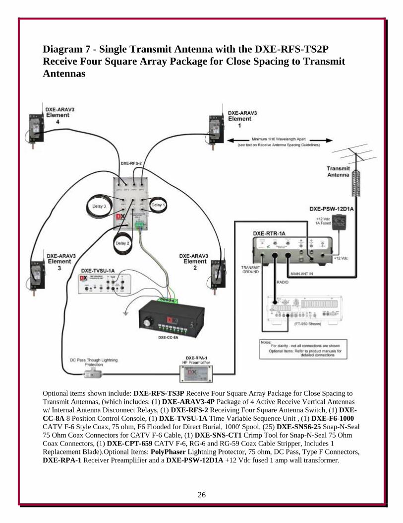
Diagram 7 shows how a DXE-RFS-TS2P Complete Receive Four Square Array Package for Close
Spacing to Transmit Antennas is connected to a transceiver that does not offer a receive antenna
input.
Diagram 8 illustrates the use of the DXE-RTR-1A with a DXE-MBVA-1UP Multi-band Vertical
Transmit Antenna (a monoband vertical antenna may also be used) one DXE-ARAV3-1P Active
Vertical Receive Antenna with Internal Antenna Disconnect Relay, and the DXE-NCC-1 Receive
Antenna Variable Phasing Controller. This combination allows the user to null strong receive
signals and noise in certain directions, opening up new reception possibilities. When using the
DXE-RTR-1A, the Multi-band Vertical transmit antenna can be phased with the Active Receive
Antenna using the DXE-NCC-1 Receive Antenna Variable Phasing Controller. The antennas being
phased should be the same polarization for optimal results.
Refer to the manual for the DXE-NCC-1 Receive Antenna Variable Phasing Controller (available
for viewing or downloading on the DX Engineering website) for more details on directional signal
and noise nulling.
21
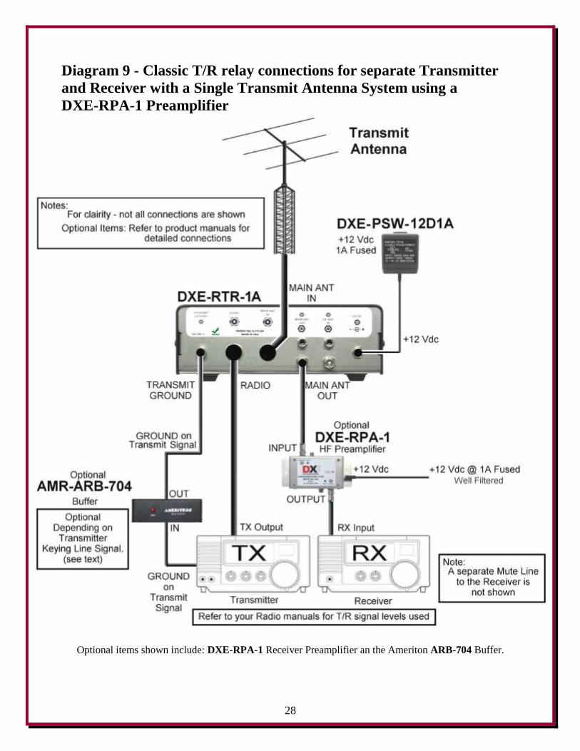
Diagram 9 demonstrates how the DXE-RTR-1A may be used in a classic T/R relay application with
an added bonus! The popular optional accessory for older receivers, the DX Engineering Receive
Preamplifier model DXE-RPA-1, may be used safely, for improving reception on the transmit antenna,
especially on higher frequencies. When the pre-amp is not required, it may be internally bypassed by
removing the DC power to it.
Set the MAIN ON - RX ANT - MAIN ON toggle switch to the RX ANT (center) position to connect
the MAIN ANT to your receiver. When you key the transmitter, the DXE-RTR-1A's automatic 4 ms
changeover from receive to transmit switches the MAIN ANT to the transmitter. Manually switching
the toggle switch to the MAIN ON (up) position connects the MAIN ANT to the transmitter, if desired
for tune up operations. The power limit for the transmitter is 200 watts.
The keying line from the transmitter* must be a Ground-On-Transmit type, as the DXE-RTR-1A
cannot accept any keying voltage. If the only keying line from the transmitter is a positive or negative
voltage type, then an Ameritron AMR-ARB-704 must be used in the transmitter keying line, as
shown in Diagram 9. The ARB-704 will accept any keying voltage, 12 volts positive or negative and
provides the Ground-On-Transmit keying for the DXE-RTR-1A.
A muting line from the transmitter which may provide a ground for an older receiver, cannot be
shared with the DXE-RTR-1A, as many old receivers* require the grounding of a high voltage for
muting.
* Refer to your transmitter and receiver instruction manuals for keying line and muting line
information and requirements.
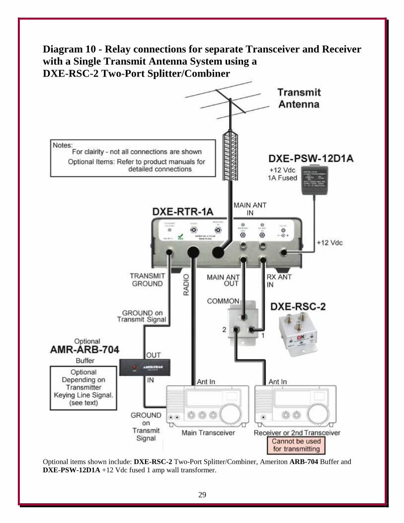
In a special application with no receive antenna connections, Diagram 10 illustrates using the DXE-
RTR-1A with an optional DXE-RSC-2 Two-Port Splitter/Combiner to allow one transmitting
antenna to be shared for simultaneous receive on two transceivers or with one transceiver and one
receiver. The second radio is isolated from transmit energy by the DXE-RTR-1A. Only the main
transceiver may be used to transmit. The second transceiver that is connected to one of the DXE-
RSC-2 outputs must be transmit inhibited using either the radio's menu settings or power output
controls set to zero to prevent system damage.
Set the MAIN ON - RX ANT - MAIN ON toggle switch to the RX ANT (center) position to connect
the MAIN ANT to both radios for simultaneous reception. When you key the main transmitter, the
DXE-RTR-1A automatically changes from receive on both radios to transmit on the MAIN ANT in
only 4 ms. The strong signal heard by the second radio is at a level that cannot damage it's front end.
Manually switching the toggle switch to the MAIN ON (up) position connects the MAIN ANT to the
main transceiver, if desired for tune up operations, or for normal operations without the second radio.
The power limit for the transmitter is 200 watts.
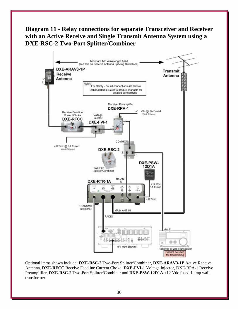
Diagram 11 demonstrates how the DXE-RSC-2 Two-Port Splitter/Combiners can be used to split the
active receive signal to the DXE-RTR-1A and a second radio. In most low band operations, the
receive antenna system will provide superior reception compared to the transmit antenna. An active
receive antenna offers the signal-to-noise advantage that allows weak DX signals to be heard which
would otherwise be covered by noise when listening with the transmit antenna. The second
transceiver that is connected to one of the DXE-RSC-2 outputs must be transmit inhibited using
either the radio's menu settings or power output controls set to zero to prevent system damage.
22
Diagram 3 - DXE-NCC-1 Receive Antenna Variable Phasing Controller
with two Active Receive Antennas
Optional items shown include: DXE-ARAV3-1P Active Vertical Receive Antennas with Internal Antenna
Disconnect Relays. DXE-NCC-1 Receive Antenna Variable Phasing Controller and DXE-PSW-12D1A +12
Vdc fused 1 amp wall transformer.
23
Diagram 4 - DXE-NCC-1 Receive Antenna Variable Phasing
Controller with two Active Receive Antennas using high power
to the transmit antenna.
Optional items shown include: DXE-AAPS3-1P Electronically Rotatable Receive Antenna System (which
includes two DXE-ARAV3-1P Active Receive Antennas and one DXE-NCC-1 Receive Antenna Variable
Phasing Controller), DXE-TVSU-1A Time Variable Sequencer Unit, Ameritron AL-811 Amplifier,
Ameriton ARB-704 Buffer, MFJ-998 Antenna Intellituner, CW Key, Foot Switch, DXE-PSW-12D1A +12
Vdc fused 1 amp wall transformer and the DXE-MBVA-1UP Multi-band Vertical Antenna.
24
Diagram 5 - Single Transmit Antenna System using a DXE-RPA-1
Preamplifier
Optional items shown include: DXE-RPA-1 Receiver Preamplifier and DXE-PSW-12D1A +12 Vdc fused 1
amp wall transformer.
25
Diagram 6 - Single Transmit Antenna System using a DXE-RBS-1
Reversible Beverage Antenna System
Optional items shown include: DXE-RBS-1P Reversible Beverage Antenna System - Two Direction, DXE-
CC-8A Control Console, DXE-FVC-1 Feedpoint Voltage Coupler, DXE-RPA-1 Receiver Preamplifier and
DXE-PSW-12D1A +12 Vdc fused 1 amp wall transformer.
26
Diagram 7 - Single Transmit Antenna with the DXE-RFS-TS2P
Receive Four Square Array Package for Close Spacing to Transmit
Antennas
Optional items shown include: DXE-RFS-TS3P Receive Four Square Array Package for Close Spacing to
Transmit Antennas, (which includes: (1) DXE-ARAV3-4P Package of 4 Active Receive Vertical Antennas
w/ Internal Antenna Disconnect Relays, (1) DXE-RFS-2 Receiving Four Square Antenna Switch, (1) DXE-
CC-8A 8 Position Control Console, (1) DXE-TVSU-1A Time Variable Sequence Unit , (1) DXE-F6-1000
CATV F-6 Style Coax, 75 ohm, F6 Flooded for Direct Burial, 1000' Spool, (25) DXE-SNS6-25 Snap-N-Seal
75 Ohm Coax Connectors for CATV F-6 Cable, (1) DXE-SNS-CT1 Crimp Tool for Snap-N-Seal 75 Ohm
Coax Connectors, (1) DXE-CPT-659 CATV F-6, RG-6 and RG-59 Coax Cable Stripper, Includes 1
Replacement Blade).Optional Items: PolyPhaser Lightning Protector, 75 ohm, DC Pass, Type F Connectors, DXE-RPA-1 Receiver Preamplifier and a DXE-PSW-12D1A +12 Vdc fused 1 amp wall transformer.
27
Diagram 8 - One Monoband or Multi-band Vertical Antenna phased
with a DXE-ARAV2-1P Active Receive Antenna using the DXE-NCC-
1 Receive Antenna Variable Phasing Controller
Optional items shown include: DXE-ARAV3-1P Active Receive Antenna, DXE-NCC-1 Receive Antenna
Variable Phasing Controller), DXE-PSW-12D1A +12 Vdc fused 1 amp wall transformer, DXE-MBVA-
1UP Multi-band Vertical Antenna and a wideband MFJ-993B automatic tuner.
28
Diagram 9 - Classic T/R relay connections for separate Transmitter
and Receiver with a Single Transmit Antenna System using a
DXE-RPA-1 Preamplifier
Optional items shown include: DXE-RPA-1 Receiver Preamplifier an the Ameriton ARB-704 Buffer.
29
Diagram 10 - Relay connections for separate Transceiver and Receiver
with a Single Transmit Antenna System using a
DXE-RSC-2 Two-Port Splitter/Combiner
Optional items shown include: DXE-RSC-2 Two-Port Splitter/Combiner, Ameriton ARB-704 Buffer and
DXE-PSW-12D1A +12 Vdc fused 1 amp wall transformer.
30
Diagram 11 - Relay connections for separate Transceiver and Receiver
with an Active Receive and Single Transmit Antenna System using a
DXE-RSC-2 Two-Port Splitter/Combiner
Optional items shown include: DXE-RSC-2 Two-Port Splitter/Combiner, DXE-ARAV3-1P Active Receive
Antenna, DXE-RFCC Receive Feedline Current Choke, DXE-FVI-1 Voltage Injector, DXE-RPA-1 Receive
Preamplifier, DXE-RSC-2 Two-Port Splitter/Combiner and DXE-PSW-12D1A +12 Vdc fused 1 amp wall
transformer.
31
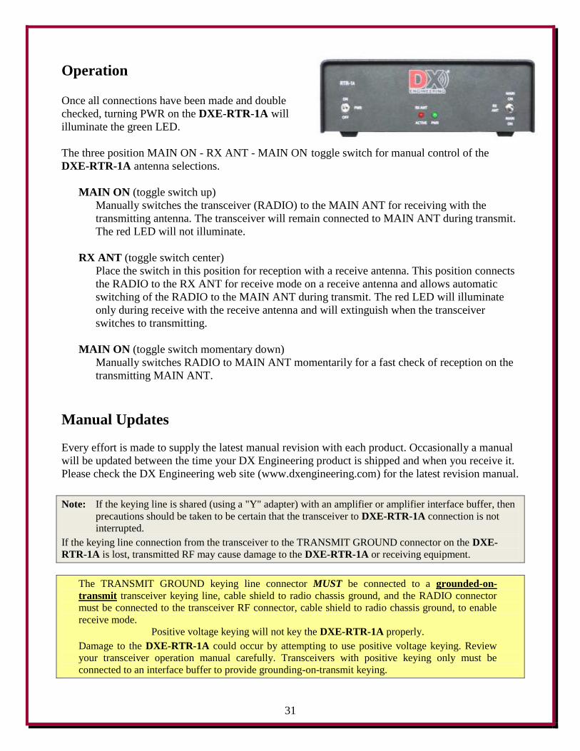
Operation Once all connections have been made and double
checked, turning PWR on the DXE-RTR-1A will
illuminate the green LED.
The three position MAIN ON - RX ANT - MAIN ON toggle switch for manual control of the
DXE-RTR-1A antenna selections.
MAIN ON (toggle switch up)
Manually switches the transceiver (RADIO) to the MAIN ANT for receiving with the
transmitting antenna. The transceiver will remain connected to MAIN ANT during transmit.
The red LED will not illuminate.
RX ANT (toggle switch center)
Place the switch in this position for reception with a receive antenna. This position connects
the RADIO to the RX ANT for receive mode on a receive antenna and allows automatic
switching of the RADIO to the MAIN ANT during transmit. The red LED will illuminate
only during receive with the receive antenna and will extinguish when the transceiver
switches to transmitting.
MAIN ON (toggle switch momentary down)
Manually switches RADIO to MAIN ANT momentarily for a fast check of reception on the
transmitting MAIN ANT.
Manual Updates
Every effort is made to supply the latest manual revision with each product. Occasionally a manual
will be updated between the time your DX Engineering product is shipped and when you receive it.
Please check the DX Engineering web site (www.dxengineering.com) for the latest revision manual.
Note: If the keying line is shared (using a "Y" adapter) with an amplifier or amplifier interface buffer, then
precautions should be taken to be certain that the transceiver to DXE-RTR-1A connection is not
interrupted.
If the keying line connection from the transceiver to the TRANSMIT GROUND connector on the DXE-
RTR-1A is lost, transmitted RF may cause damage to the DXE-RTR-1A or receiving equipment.
The TRANSMIT GROUND keying line connector MUST be connected to a grounded-on-
transmit transceiver keying line, cable shield to radio chassis ground, and the RADIO connector
must be connected to the transceiver RF connector, cable shield to radio chassis ground, to enable
receive mode.
Positive voltage keying will not key the DXE-RTR-1A properly.
Damage to the DXE-RTR-1A could occur by attempting to use positive voltage keying. Review
your transceiver operation manual carefully. Transceivers with positive keying only must be
connected to an interface buffer to provide grounding-on-transmit keying.
32
Optional Items
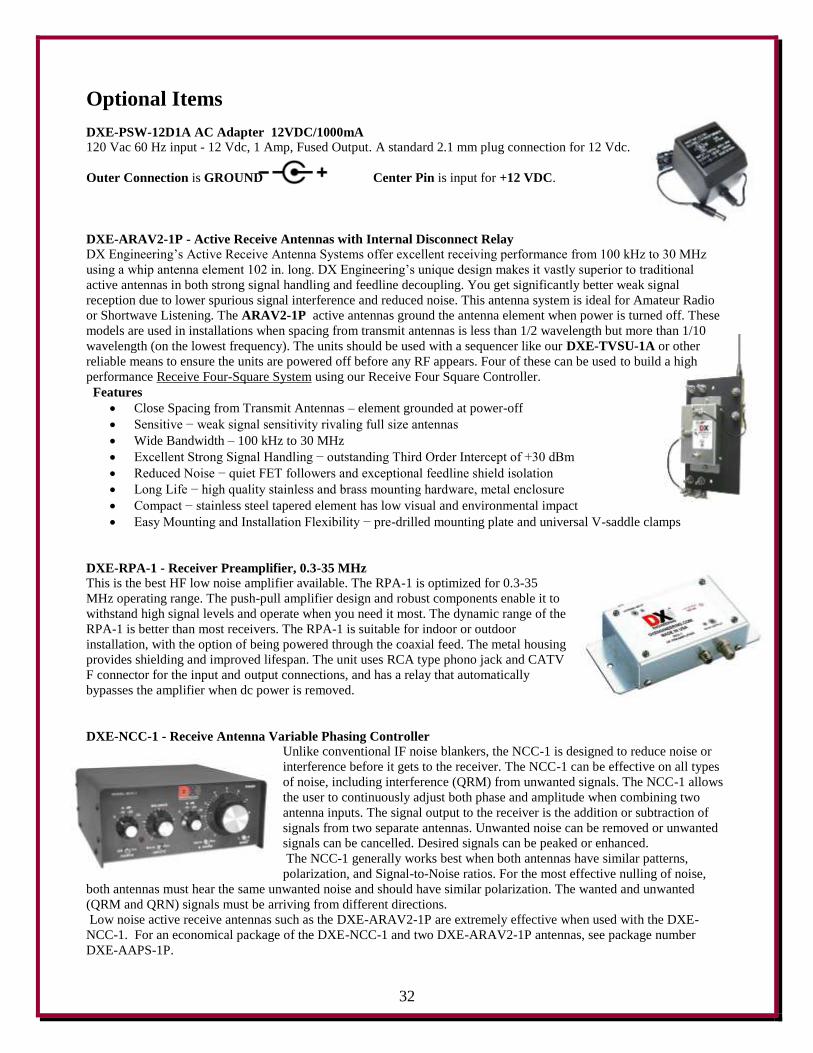
DXE-PSW-12D1A AC Adapter 12VDC/1000mA
120 Vac 60 Hz input - 12 Vdc, 1 Amp, Fused Output. A standard 2.1 mm plug connection for 12 Vdc.
Outer Connection is GROUND Center Pin is input for +12 VDC.
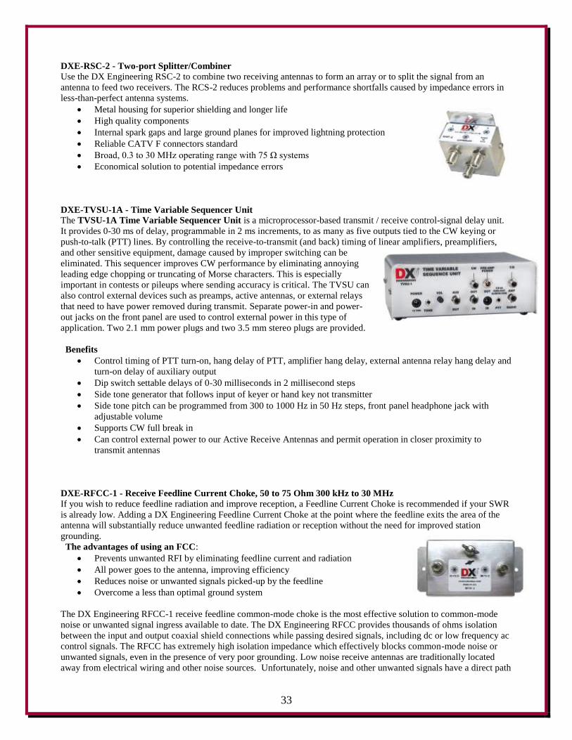
DXE-ARAV2-1P - Active Receive Antennas with Internal Disconnect Relay
DX Engineering’s Active Receive Antenna Systems offer excellent receiving performance from 100 kHz to 30 MHz
using a whip antenna element 102 in. long. DX Engineering’s unique design makes it vastly superior to traditional
active antennas in both strong signal handling and feedline decoupling. You get significantly better weak signal
reception due to lower spurious signal interference and reduced noise. This antenna system is ideal for Amateur Radio
or Shortwave Listening. The ARAV2-1P active antennas ground the antenna element when power is turned off. These
models are used in installations when spacing from transmit antennas is less than 1/2 wavelength but more than 1/10
wavelength (on the lowest frequency). The units should be used with a sequencer like our DXE-TVSU-1A or other
reliable means to ensure the units are powered off before any RF appears. Four of these can be used to build a high
performance Receive Four-Square System using our Receive Four Square Controller.
Features
Close Spacing from Transmit Antennas – element grounded at power-off
Sensitive − weak signal sensitivity rivaling full size antennas
Wide Bandwidth – 100 kHz to 30 MHz
Excellent Strong Signal Handling − outstanding Third Order Intercept of +30 dBm
Reduced Noise − quiet FET followers and exceptional feedline shield isolation
Long Life − high quality stainless and brass mounting hardware, metal enclosure
Compact − stainless steel tapered element has low visual and environmental impact
Easy Mounting and Installation Flexibility − pre-drilled mounting plate and universal V-saddle clamps
DXE-RPA-1 - Receiver Preamplifier, 0.3-35 MHz
This is the best HF low noise amplifier available. The RPA-1 is optimized for 0.3-35
MHz operating range. The push-pull amplifier design and robust components enable it to
withstand high signal levels and operate when you need it most. The dynamic range of the
RPA-1 is better than most receivers. The RPA-1 is suitable for indoor or outdoor
installation, with the option of being powered through the coaxial feed. The metal housing
provides shielding and improved lifespan. The unit uses RCA type phono jack and CATV
F connector for the input and output connections, and has a relay that automatically
bypasses the amplifier when dc power is removed.
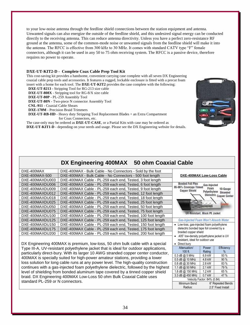
DXE-NCC-1 - Receive Antenna Variable Phasing Controller
Unlike conventional IF noise blankers, the NCC-1 is designed to reduce noise or
interference before it gets to the receiver. The NCC-1 can be effective on all types
of noise, including interference (QRM) from unwanted signals. The NCC-1 allows
the user to continuously adjust both phase and amplitude when combining two
antenna inputs. The signal output to the receiver is the addition or subtraction of
signals from two separate antennas. Unwanted noise can be removed or unwanted
signals can be cancelled. Desired signals can be peaked or enhanced.
The NCC-1 generally works best when both antennas have similar patterns,
polarization, and Signal-to-Noise ratios. For the most effective nulling of noise,
both antennas must hear the same unwanted noise and should have similar polarization. The wanted and unwanted
(QRM and QRN) signals must be arriving from different directions.
Low noise active receive antennas such as the DXE-ARAV2-1P are extremely effective when used with the DXE-
NCC-1. For an economical package of the DXE-NCC-1 and two DXE-ARAV2-1P antennas, see package number
DXE-AAPS-1P.
33
DXE-RSC-2 - Two-port Splitter/Combiner
Use the DX Engineering RSC-2 to combine two receiving antennas to form an array or to split the signal from an
antenna to feed two receivers. The RCS-2 reduces problems and performance shortfalls caused by impedance errors in
less-than-perfect antenna systems.
Metal housing for superior shielding and longer life
High quality components
Internal spark gaps and large ground planes for improved lightning protection
Reliable CATV F connectors standard
Broad, 0.3 to 30 MHz operating range with 75 Ω systems
Economical solution to potential impedance errors
DXE-TVSU-1A - Time Variable Sequencer Unit
The TVSU-1A Time Variable Sequencer Unit is a microprocessor-based transmit / receive control-signal delay unit.
It provides 0-30 ms of delay, programmable in 2 ms increments, to as many as five outputs tied to the CW keying or
push-to-talk (PTT) lines. By controlling the receive-to-transmit (and back) timing of linear amplifiers, preamplifiers,
and other sensitive equipment, damage caused by improper switching can be
eliminated. This sequencer improves CW performance by eliminating annoying
leading edge chopping or truncating of Morse characters. This is especially
important in contests or pileups where sending accuracy is critical. The TVSU can
also control external devices such as preamps, active antennas, or external relays
that need to have power removed during transmit. Separate power-in and power-
out jacks on the front panel are used to control external power in this type of
application. Two 2.1 mm power plugs and two 3.5 mm stereo plugs are provided.
Benefits
Control timing of PTT turn-on, hang delay of PTT, amplifier hang delay, external antenna relay hang delay and
turn-on delay of auxiliary output
Dip switch settable delays of 0-30 milliseconds in 2 millisecond steps
Side tone generator that follows input of keyer or hand key not transmitter
Side tone pitch can be programmed from 300 to 1000 Hz in 50 Hz steps, front panel headphone jack with
adjustable volume
Supports CW full break in
Can control external power to our Active Receive Antennas and permit operation in closer proximity to
transmit antennas
DXE-RFCC-1 - Receive Feedline Current Choke, 50 to 75 Ohm 300 kHz to 30 MHz If you wish to reduce feedline radiation and improve reception, a Feedline Current Choke is recommended if your SWR
is already low. Adding a DX Engineering Feedline Current Choke at the point where the feedline exits the area of the
antenna will substantially reduce unwanted feedline radiation or reception without the need for improved station
grounding.
The advantages of using an FCC:
Prevents unwanted RFI by eliminating feedline current and radiation
All power goes to the antenna, improving efficiency
Reduces noise or unwanted signals picked-up by the feedline
Overcome a less than optimal ground system
The DX Engineering RFCC-1 receive feedline common-mode choke is the most effective solution to common-mode
noise or unwanted signal ingress available to date. The DX Engineering RFCC provides thousands of ohms isolation
between the input and output coaxial shield connections while passing desired signals, including dc or low frequency ac
control signals. The RFCC has extremely high isolation impedance which effectively blocks common-mode noise or
unwanted signals, even in the presence of very poor grounding. Low noise receive antennas are traditionally located
away from electrical wiring and other noise sources. Unfortunately, noise and other unwanted signals have a direct path
34
to your low-noise antenna through the feedline shield connections between the station equipment and antenna.
Unwanted signals can also energize the outside of the feedline shield, and this undesired signal energy can be conducted
directly to the receiving antenna. This can reduce antenna directivity. Unless you have a perfect zero-resistance RF
ground at the antenna, some of the common-mode noise or unwanted signals from the feedline shield will make it into
the antenna. The RFCC is effective from 300 kHz to 30 MHz. It comes with standard CATV type “F” female
connectors, although it can be used in any 50 to 75 ohm receiving system. The RFCC is a passive device, therefore
requires no power to operate.
DXE-UT-KIT2-D - Complete Coax Cable Prep Tool Kit This cost-saving kit provides a handsome, convenient carrying case complete with all seven DX Engineering
coaxial cable prep tools and accessories. It features a rugged, lockable enclosure is fitted with a precut foam
insert with a home for each tool. The DXE-UT-KIT2 provides the case complete with the following:
DXE-UT-8213 - Stripping Tool for RG-213 size cable
DXE-UT-808X - Stripping tool for RG-8/X size cable
DXE-UT-80P - PL-259 Assembly Tool
DXE-UT-80N - Two-piece N connector Assembly Tool
CNL-911 - Coaxial Cable Shears
DXE-170M - Precision Braid Trimmers
DXE-UT-RB-HD - Heavy duty Stripping Tool Replacement Blades + an Extra Compartment
for Coax Connectors, etc.
The case-only may be ordered as DXE-UT-CASE, or a Partial Kits with case may be ordered as
DXE-UT-KIT1-D - depending on your needs and usage. Please see the DX Engineering website for details.
DX Engineering 400MAX 50 ohm Coaxial Cable
DXE-400MAX DXE-400MAX - Bulk Cable - No Connectors - Sold by the foot DXE-400MAX Low-Loss Cable DXE-400MAX-500 DXE-400MAX - Bulk Cable - No Connectors - 500 foot length
DXE-400MAXDU003 DXE-400MAX Cable - PL-259 each end, Tested, 3 foot length
DXE-400MAXDU006 DXE-400MAX Cable - PL-259 each end, Tested, 6 foot length DXE-400MAXDU009 DXE-400MAX Cable - PL-259 each end, Tested, 9 foot length
DXE-400MAXDU012 DXE-400MAX Cable - PL-259 each end, Tested, 12 foot length
DXE-400MAXDU018 DXE-400MAX Cable - PL-259 each end, Tested, 18 foot length
DXE-400MAXDU025 DXE-400MAX Cable - PL-259 each end, Tested, 25 foot length
DXE-400MAXDU050 DXE-400MAX Cable - PL-259 each end, Tested, 50 foot length
DXE-400MAXDU075 DXE-400MAX Cable - PL-259 each end, Tested, 75 foot length
DXE-400MAXDU100 DXE-400MAX Cable - PL-259 each end, Tested, 100 foot length
DXE-400MAXDU125 DXE-400MAX Cable - PL-259 each end, Tested, 125 foot length Gas-Injected Foam Won’t Absorb Water
DXE-400MAXDU150 DXE-400MAX Cable - PL-259 each end, Tested, 150 foot length Low-loss, gas-injected foam polyethylene dielectric bonded tape foil covered by a braided copper shield
.405” low-density polyethylene jacket is UV resistant, ideal for outdoor use
Direct bury
DXE-400MAXDU175 DXE-400MAX Cable - PL-259 each end, Tested, 175 foot length
DXE-400MAXDU200 DXE-400MAX Cable - PL-259 each end, Tested, 200 foot length
DX Engineering 400MAX is premium, low-loss, 50 ohm bulk cable with a special Type III-A, UV-resistant polyethylene jacket that is ideal for outdoor applications, particularly direct-bury. With its larger 10 AWG stranded copper center conductor, 400MAX is specially suited for high-power amateur stations, providing a lower loss solution for long cable runs at any power level. The high-quality construction continues with a gas-injected foam polyethylene dielectric, followed by the highest level of shielding from bonded aluminum tape covered by a tinned copper shield braid. DX Engineering 400MAX Low-Loss 50 ohm Bulk Coaxial Cable uses standard PL-259 or N connectors.
Attenuation/ 100 ft.
Power Rating
Efficiency %
0.3 dB @ 5 MHz 6.9 kW 93 %
0.5 dB @ 10 MHz 4.8 kW 90 %
0.8 dB @ 30 MHz 2.8 kW 83 %
1.1 dB @ 50 MHz 2.1 kW 79 %
1.8 dB @ 150 MHz 1.2 kW 65 %
3.3 dB @ 450 MHz 0.7 kW 47 %
Velocity Factor: 84% (0.84) Minimum Bend
Radius:
6” Repeated Bends
2.5” Fixed Install
35
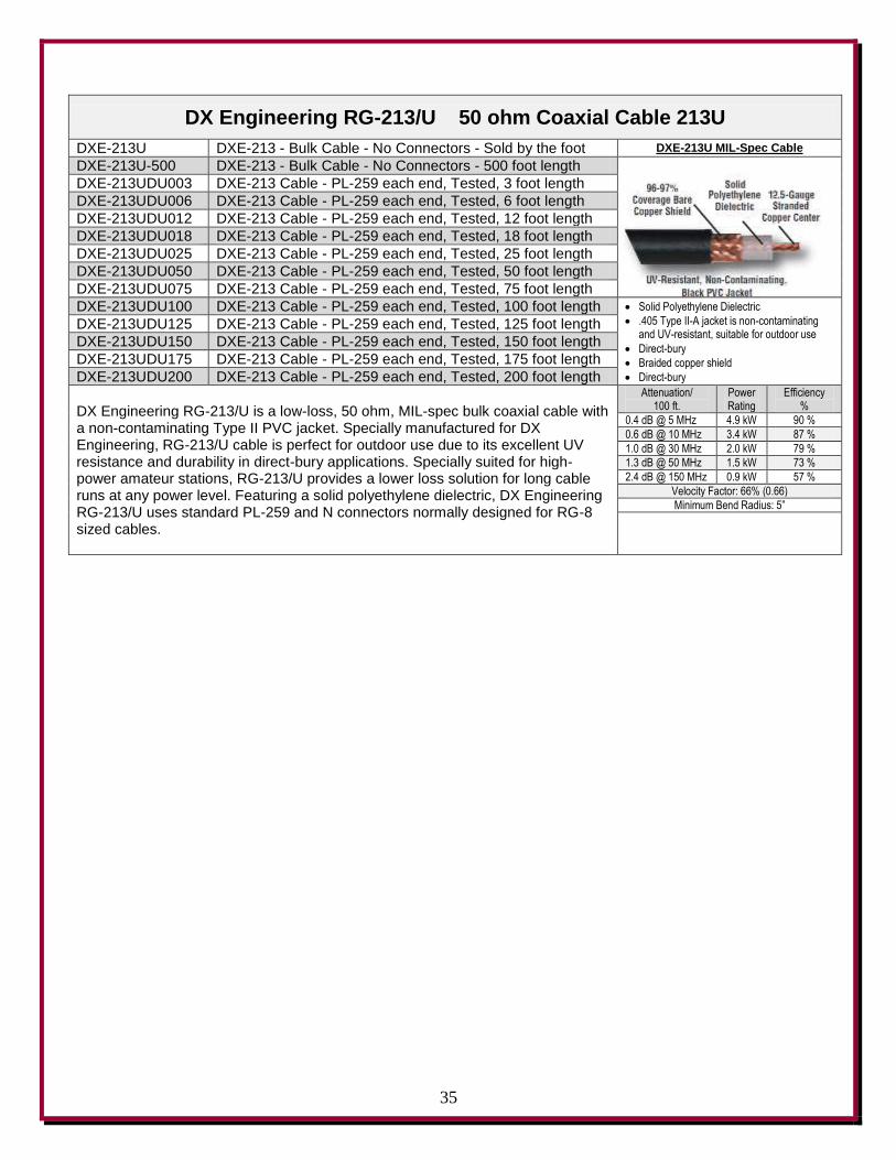
DX Engineering RG-213/U 50 ohm Coaxial Cable 213U
DXE-213U DXE-213 - Bulk Cable - No Connectors - Sold by the foot DXE-213U MIL-Spec Cable
DXE-213U-500 DXE-213 - Bulk Cable - No Connectors - 500 foot length
DXE-213UDU003 DXE-213 Cable - PL-259 each end, Tested, 3 foot length
DXE-213UDU006 DXE-213 Cable - PL-259 each end, Tested, 6 foot length
DXE-213UDU012 DXE-213 Cable - PL-259 each end, Tested, 12 foot length
DXE-213UDU018 DXE-213 Cable - PL-259 each end, Tested, 18 foot length
DXE-213UDU025 DXE-213 Cable - PL-259 each end, Tested, 25 foot length
DXE-213UDU050 DXE-213 Cable - PL-259 each end, Tested, 50 foot length
DXE-213UDU075 DXE-213 Cable - PL-259 each end, Tested, 75 foot length
DXE-213UDU100 DXE-213 Cable - PL-259 each end, Tested, 100 foot length Solid Polyethylene Dielectric
.405 Type II-A jacket is non-contaminating and UV-resistant, suitable for outdoor use
Direct-bury
Braided copper shield
Direct-bury
DXE-213UDU125 DXE-213 Cable - PL-259 each end, Tested, 125 foot length
DXE-213UDU150 DXE-213 Cable - PL-259 each end, Tested, 150 foot length
DXE-213UDU175 DXE-213 Cable - PL-259 each end, Tested, 175 foot length
DXE-213UDU200 DXE-213 Cable - PL-259 each end, Tested, 200 foot length
DX Engineering RG-213/U is a low-loss, 50 ohm, MIL-spec bulk coaxial cable with a non-contaminating Type II PVC jacket. Specially manufactured for DX Engineering, RG-213/U cable is perfect for outdoor use due to its excellent UV resistance and durability in direct-bury applications. Specially suited for high-power amateur stations, RG-213/U provides a lower loss solution for long cable runs at any power level. Featuring a solid polyethylene dielectric, DX Engineering RG-213/U uses standard PL-259 and N connectors normally designed for RG-8 sized cables.
Attenuation/ 100 ft.
Power Rating
Efficiency %
0.4 dB @ 5 MHz 4.9 kW 90 %
0.6 dB @ 10 MHz 3.4 kW 87 %
1.0 dB @ 30 MHz 2.0 kW 79 %
1.3 dB @ 50 MHz 1.5 kW 73 %
2.4 dB @ 150 MHz 0.9 kW 57 %
Velocity Factor: 66% (0.66) Minimum Bend Radius: 5”
36
Technical Support
If you have questions about this product, or if you experience difficulties during the installation, contact DX
Engineering at (330) 572-3200. You can also e-mail us at:
For best service, please take a few minutes to review this manual before you call.
This unit is RoHS (Reduction of Hazardous Substances) compliant. The components, including the solder used
are all lead free. If you decide to do any modifications or internal repairs, you should use only lead free solder
and lead free soldering tools. Lead free solder melts approximately 100 degrees higher than the old leaded
solder, so you may need to upgrade your current soldering system.
Warranty All products manufactured by DX Engineering are warranted to be free from defects in material and workmanship for a
period of one (1) year from date of shipment. DX Engineering’s sole obligation under these warranties shall be to issue
credit, repair or replace any item or part thereof which is proved to be other than as warranted; no allowance shall be
made for any labor charges of Buyer for replacement of parts, adjustment or repairs, or any other work, unless such
charges are authorized in advance by DX Engineering. If DX Engineering’s products are claimed to be defective in
material or workmanship, DX Engineering shall, upon prompt notice thereof, issue shipping instructions for return to
DX Engineering (transportation-charges prepaid by Buyer). Every such claim for breach of these warranties shall be
deemed to be waived by Buyer unless made in writing. The above warranties shall not extend to any products or parts
thereof which have been subjected to any misuse or neglect, damaged by accident, rendered defective by reason of
improper installation, damaged from severe weather including floods, or abnormal environmental conditions such as
prolonged exposure to corrosives or power surges, or by the performance of repairs or alterations outside of our plant,
and shall not apply to any goods or parts thereof furnished by Buyer or acquired from others at Buyer’s specifications.
In addition, DX Engineering’s warranties do not extend to other equipment and parts manufactured by others except to
the extent of the original manufacturer’s warranty to DX Engineering. The obligations under the foregoing warranties
are limited to the precise terms thereof. These warranties provide exclusive remedies, expressly in lieu of all other
remedies including claims for special or consequential damages. SELLER NEITHER MAKES NOR ASSUMES ANY
OTHER WARRANTY WHATSOEVER, WHETHER EXPRESS, STATUTORY, OR IMPLIED, INCLUDING
WARRANTIES OF MERCHANTABILITY AND FITNESS, AND NO PERSON IS AUTHORIZED TO ASSUME
FOR DX ENGINEERING ANY OBLIGATION OR LIABILITY NOT STRICTLY IN ACCORDANCE WITH THE
FOREGOING.
©DX Engineering 2013
DX Engineering®, DXE®, DX Engineering, Inc.®, Hot Rodz®, Maxi-Core®, DX Engineering THUNDERBOLT™,
DX Engineering Yagi Mechanical®, EZ-BUILD®, TELREX® and Gorilla Grip® Stainless Steel Boom Clamps, are
trademarks of PDS Electronics, Inc. No license to use or reproduce any of these trademarks or other trademarks is given
or implied. All other brands and product names are the trademarks of their respective owners.
Specifications subject to change without notice.