Embed Size (px)
Citation preview
DATE OCT 31 2011
RECD. NOV 01 2011
DOCKET08-AFC-8
1
Michael J. Carroll Marc T. Campopiano LATHAM & WATKINS LLP 650 Town Center Drive, Suite 2000 Costa Mesa, CA 92626 (714) 540-1235
STATE OF CALIFORNIA ENERGY RESOURCES
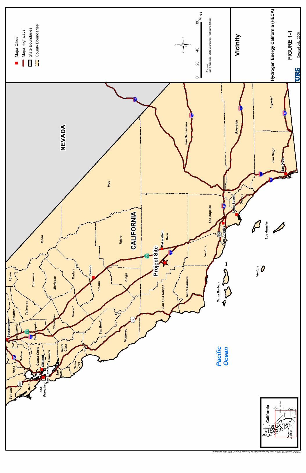
CONSERVATION AND DEVELOPMENT COMMISSION In the Matter of: ) Docket No. 08-AFC-8 ) REVISED APPLICATION FOR ) APPLICANT'S STATUS REPORT NO. 9 CERTIFICATION ) FOR THE HYDROGEN ENERGY ) CALIFORNIA PROJECT ) --------------------------------------------) Applicant Hydrogen Energy California LLC (Applicant) hereby files its Status Report 9 with respect to the Hydrogen Energy California Project (HECA or Project). Introduction and Project Overview Hydrogen Energy California LLC is proposing to design, construct and operate an Integrated Gasification Combined Cycle (IGCC) power facility with carbon capture, utilization and sequestration (CCUS) in Kern County, California. The Hydrogen Energy California Project will gasify a 75% coal and 25% petroleum coke (petcoke) fuel blend to produce a hydrogen-rich gas which will fuel a combustion turbine operating in combined cycle mode. The Project will generate approximately 400 MW (gross) and 288 MW (net) of low-carbon baseload electricity while capturing carbon dioxide (CO2) and transporting it for enhanced oil recovery (EOR) and sequestration. The Project is designed to achieve at least 90% CO2 capture efficiency while permanently sequestering more than 2.0 million tons per year. The Project Site is located near the Elk Hills Field and the unincorporated community of Tupman in western Kern County, California, as shown on Figure 1-1, Project Vicinity Map.
Project Modifications SCS Energy California LLC acquired 100% ownership of Hydrogen Energy California LLC from BP Alternative Energy North America Inc. and Rio Tinto Hydrogen Energy LLC on September 2, 2011. SCS Energy California LLC is an affiliate of SCS Energy
2
LLC (SCS Energy). SCS Energy is a private power plant development company headquartered in Concord, Massachusetts. SCS Energy has modified the Project design to better meet market demands. Unless otherwise noted below, Project design elements will not appreciably change from those detailed in previous regulatory filings. Basic Project components remain unchanged:
IGCC 90% CCUS via EOR at the adjacent Elk Hills Field Project Site State-of-the-art air emissions controls Brackish make-up water supplied by the Buena Vista Water Storage District Zero liquid discharge
Notable modifications are detailed below: Mitsubishi Heavy Industries (MHI) oxygen-blown dry feed gasification technology
has been selected. A new rail spur will be constructed to the Project Site in order to facilitate feedstock
and equipment delivery and fertilizer and product off-take. This modification will help to reduce truck traffic on local roads.
A new, integrated fertilizer plant will produce approximately 1 million tons per year of nearly carbon free nitrogen-based fertilizer.
The 75% coal, 25% petcoke fuel blend will be used for the life of the facility. Natural gas will be used for start-up only, not for gas turbine routine operation. A
natural gas interconnection will be made with a PG&E natural gas pipeline located approximately 8 miles north of the Project Site.
Potable water will be delivered from a new West Kern Water District potable water production site less than 1 mile away or from new on-site well(s), thereby eliminating the need for a 5.5 mile potable water line.
Location
The combined Project Site and Controlled Area remain the same as detailed in previous filings. The combined 1,101 acres are located in south-central California near the unincorporated community of Tupman, approximately 7 miles west of the city of Bakersield, as shown on Figure 1-1, Project Vicinity Map. The Project Site and vicinity is predominantly used for agricultural purposes, including cultivation of cotton, alfalfa and onions.
3
Permitting The Project is subject to regulatory oversight by federal, state and regional/local agencies. At the federal level, the Project is subject to environmental review under the National Environmental Policy Act (NEPA), with the DOE serving as Lead Agency. At the state level, the project will be subject to the California Environmental Quality Act (CEQA) with the California Energy Commission (CEC) serving as Lead Agency. The DOE and CEC will be working together to combine these regulatory processes in a manner that enhances public involvement.
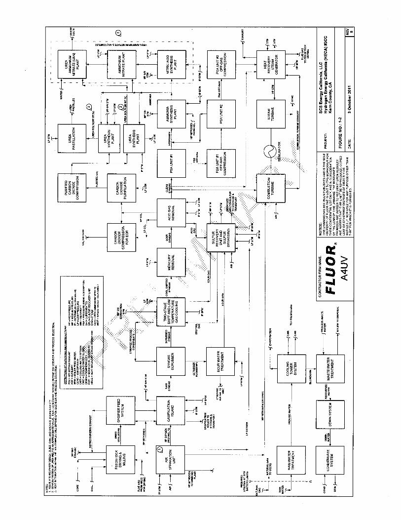
Process Overview The Project design consists of an IGCC polygeneration plant that will : (1) use coal/petcoke gasification to create hydrogen while capturing over 90% of the CO2, (2) use a hydrogen-fired combined cycle power block, (3) include a hydrogen-fed, 90% carbon-free fertilizer plant, and (4) sequester the captured CO2 by using it for EOR at the adjacent Elk Hills Field. Gasification
The Project uses Mitsubishi Heavy Industries (MHI) gasification technology. The MHI oxygen-blown gasifier is a pressurized, upflow, entrained-flow slagging reactor with a two-stage operation. The MHI gasifier is a dry-feed system and the reactor internal is protected by a membrane wall. Gasification is a chemical conversion process that occurs in a reducing environment. Gasification differs from combustion in that gasification produces syngas, an intermediate product that can then be used for purposes such as generating electricity or producing chemicals.
The gasifier is fed a blend of coal and petcoke along with oxygen. Coal will be delivered to the rail unloading and transfer system at the Site. The coal is unloaded from unit trains and conveyed to coal storage. Conveyors will be fully enclosed for weather protection and to control fugitive dust. Coal feedstock buildings will be fully enclosed. Dust suppression spray systems, dust collection systems, and/or transfer design are used to control fugitive dust.
The gasification process begins with the solid feedstocks being dried by recycling hot exhaust gas through the solid feed mill. The solid feed is metered into the mill and ground and classified to meet size specifications. The feed stream is transported into pressurized feed surge storage and then pneumatically fed to the gasifier feed injectors. The feed stream chemically reacts with the oxygen in the gasifiers to form syngas, composed mostly of hydrogen and carbon monoxide. The high temperature ensures complete gasification of the feedstock and traps inorganic matter, like ash and metal, in a glassy matrix material. This material, referred to as gasification solids, is inert and can be beneficially used.
4
The syngas leaving the gasifiers is cooled in an efficient heat recovery system and cleaned in preparation as feedstock to the gas turbines. Post gasification treatment for syngas includes removal of entrained particulates, shift conversion of carbon monoxide and water to hydrogen and CO2, mercury removal, and acid gas removal. The sulfur in the syngas is recovered and converted into a liquid sulfur product for sale.
Fertilizer Production
A portion of clean syngas will be sent to the pressure swing adsorption (PSA) unit to generate a high-purity hydrogen gas stream for use as a feedstock for the ammonia. The off-gas from the PSA unit is compressed and sent to the HRSG for use as duct-burner fuel. Two PSA units in series are utilized to maximize hydrogen recovery. A high-purity hydrogen stream (from the PSA unit) and nitrogen (from the ASU) are the two primary feedstocks to the ammonia plant. Cold liquid ammonia is stored in a tank at atmospheric pressure. A vapor recovery system is included to prevent any product losses. The liquid ammonia will be pumped from the tank to the various users within the facility. The liquid ammonia is the feedstock for the fertilizer products, including urea and UAN. There is a large degree of heat integration between the fertilizer plant and the power plant. The fertilizer plant is not self sufficient on steam and requires a large amount of medium pressure steam that is generated by the power plant HRSG. Additionally, the Load Serving Entities have indicated the desirability for some portion of the power output to be dispatchable. The fertilizer plant production and product storage capability is an essential and integral component necessary to achieve a dispatchable power generation profile.
Power Block
The clean syngas also will be used as fuel in the combined cycle power block. The Project combined cycle power block will include one single-shaft nominal 405 MWe MHI M501G “G” class advanced combustion turbine (CT) / steam turbine (ST) / generator configured to utilize syngas, one heat recovery steam generator (HRSG), and a water cooled surface condenser. The CT, HRSG, and ST will convert chemical energy contained in the syngas fuel to electricity through the shaft power developed by the CT and ST generator and through the thermal energy recovered from the CT exhaust. This exhaust gas is converted to high-energy steam in the HRSG and combined with the high-energy steam recovered in the gasification process to generate additional electricity in the ST. The “G” class machine is arranged in a single shaft configuration where the CT and ST share a common shaft / generator.
5
The facility will produce a nominal 400 MW, with up to 288 MW of dispatchable power for the grid, and will produce approximately 1 million tons per year of nitrogen-based fertilizer as well as liquid sulfur for sale. At least 90% of the carbon in the raw syngas will be converted into CO2 during steady state operation, which will be captured, compressed, and transported by pipeline for EOR and sequestration at the adjacent Elk Hills Field. A simplified block flow diagram for the Project is shown in Figure 1-2, Overall Block Flow Diagram.
Major Project resource inputs and outputs are detailed below.
Resource Inputs Petcoke and Western Coal – The Project will use a blend of 75% coal and 25% petcoke. Petcoke will be supplied from refineries in California, and/or other regional sources. The petcoke that will be used for the Project is a by-product from the oil refining process which is predominantly exported overseas for use as a low-grade fuel. Petcoke will be blended with Western coal to diversify the feedstock supply. Natural Gas Supply – Natural gas will be used for gas turbine start-up. A natural gas interconnection will be made with a PG&E natural gas pipeline located approximately 8 miles north of the Project Site. The interconnect will consist of one tap off the existing natural gas line, one meter set, one service pipeline service connection, and a pressure limiting station located on the Project Site. Brackish Water Supply Pipeline – The Project will utilize brackish groundwater supplied from the Buena Vista Water Storage District located to the northwest. The raw water supply pipeline will be approximately 18 miles in length. Oxygen - The gasification process requires high-pressure, high-purity oxygen (95% volume). The oxygen is supplied from the Air Separation Unit, which separates and purifies oxygen and nitrogen from the ambient air.
Resource Outputs Electrical Transmission Line – An electrical transmission line will interconnect the Project to the CAISO grid. The expected tie in will be on PG&E’s 230 KV transmission system. CO2 Pipeline – Carbon dioxide will be compressed and transported by pipeline to the adjacent Elk Hills Field for CO2 EOR and sequestration. The CO2 pipeline is approximately 4 miles in length.
6
Nitrogen-Based Fertilizer - Approximately 1 million tons per year of nitrogen-based fertilizer will be produced at the facility. The fertilizer product(s) will be stored onsite for shipment via railcars or trucks. Liquid Sulfur– Through an oxidation and cleaning process the sulfur in the syngas is converted to a purified degassed liquid sulfur. The degassed liquid sulfur will be stored in an onsite tank for shipment via railcars or tank trucks. Gasification Solids - Gasification solids are comprised of vitrified (glass like) material produced by melting the mineral matter in the coal and petcoke and small amounts of unconverted carbon that exit the gasifier. The low-carbon gasification solids will be washed and then transported off-site by rail or truck for sale or disposal. Wastewater - The Project has been designed for Zero Liquid Discharge (ZLD) and therefore will not discharge surface, waste or storm water off site. Wastewater produced internally will be fully recycled and reused. Any solid materials will be trucked to an approved off-site material disposal facility in accordance with applicable regulations and permit conditions. Sanitary wastewater from restrooms, showers, and kitchens will be conveyed by an underground gravity collection system and discharged to a private on-site sewage disposal system consisting of a conventional septic tank and leach field. Emissions Controls
The Project will produce dispatchable baseload electricity while substantially reducing greenhouse gas emissions by capturing CO2 and transporting it for EOR and sequestration. Furthermore, the Project will employ Best Available Control Technology (BACT) to control project emissions. The following is a summary of the emission control equipment used on the Project:
90% of the Project CO2 emissions will be reduced through EOR and
sequestration.
The Project will use a state-of-the-art emissions control process to minimize sulfur dioxide emissions.
The Project incorporates post-combustion control technologies to meet BACT
requirements. The HRSG includes a selective catalytic reduction (SCR) system to minimize the stack nitrogen oxide emissions and a carbon monoxide oxidation catalyst to control carbon monoxide and volatile organic compounds emissions.
Mercury capture technology consisting of fixed beds of sulfur-impregnated
activated carbon will convert more than 95% of the mercury present in syngas to a stable mercuric sulfide (HgS) product captured in the catalyst.
7
The feedstock solids handling system includes rail/truck unloading using a conveyor system to transport the feedstock to storage silos. All coal feedstock buildings are fully enclosed. Dust suppression spray systems, dust collection systems, and/or transfer design are used to control fugitive dust.
The cooling towers will include high-efficiency mist eliminators to minimize
particulate emissions and reduce water losses.
A Continuous Emissions Monitoring System (CEMS) will be installed on the HRSG and other stack emission sources required by applicable regulations and permit conditions. The CEMS records nitrogen oxide, oxygen, and carbon monoxide levels in order to demonstrate facility compliance with local, state, and federal emission requirements. Each CEMS system undergoes periodic calibration, audits, and testing to verify accuracy.
Key Project Benefits
The Project will provide numerous benefits at the local, regional, state, national and global levels. Among these benefits are the following:
1. Helping to Ensure Adequate Supplies of Electricity The Project will provide approximately 288 MW of new, dispatchable baseload low-carbon generating capacity. The CEC estimates that the state will need to add over 9,000 MW of capacity between 2008 and 2018 to meet demand1. 2. Protecting the Environment At least 90% of the CO2 in the raw syngas will be captured in a high-purity CO2 stream during steady-state operation, compressed, and transported by pipeline for injection into secure geologic formations for EOR and sequestration. The Project will prevent the release of more than 2 million tons (roughly equivalent to the CO2 output of 500,000 automobiles) per year of greenhouse gases to the atmosphere by sequestering them underground. The Project will employ state-of-the-art emission control technology to achieve very low criteria pollutant emissions. The Project will conserve fresh water sources by using brackish groundwater for Project process water needs. Direct surface water discharge of industrial wastewater will be eliminated through the use of ZLD technology.
3. Protecting Domestic Energy Supplies The Project will conserve domestic energy supplies, thereby enhancing energy security. The Project will advance technology to reduce stress on U.S. natural gas supplies by using a by-product from the oil refining process and coal to generate electricity. In addition, the Project will produce additional energy from existing California oil fields by
1 California Energy Commission, 2007. 2007 Integrated Energy Policy Report. Report Number CEC-100-2007-008-CMF-ES.
8
injecting CO2 and increasing production by an estimated 10 to 20%. 4. Promoting Hydrogen Infrastructure The Project will increase the supply of hydrogen available to support the state’s goal of energy independence as expressed in California Executive Order S-7-04, which mandates the development of a hydrogen infrastructure and transportation in California. The Project is poised to supplement the quantities of hydrogen necessary for these future energy and transportation technologies and support California’s role as a world leader in clean energy. 5. Stimulating the Local and California Economy The Project will boost the local and California economy. At the peak of construction, HECA will employ an estimated 2,000 workers, and will provide up to 140 permanent operational positions once completed. The Project will generate an economic impact of $6.4 billion in Kern County during construction and the first 20 years of operation.
6. Increase Domestic Production of Fertilizer The Project will produce approximately 1 million tons per year of nearly carbon-free domestic fertilizer that will be available for regional markets.
Schedule The milestones for the Project are anticipated to be as follows: HECA submits updated Project application materials2 March 2012 Start of construction June 2013 Completion of construction October 2016 Commissioning and initial startup October 2016 through August 2017 Commercial operation of the Project September 2017 Public Outreach The Applicant is committed to maintaining and building upon past public outreach efforts and will actively seek opportunities to engage the public in the decision making process. The Project has retained the HECA Information Center located at 189 East Front Street Buttonwillow, CA 93205. In addition, the Project has recently updated the “Project News” section of the website, which can now be accessed at (http://hydrogenenergycalifornia.com/) and will continue to post Project-related news, educational materials and opportunities for community involvement as information becomes available. In addition, in October 2011, HECA representatives met with Clean Air Task Force to provide a Project overview and update, and also met with Congressman Kevin McCarthy to provide a
2 Including responses to outstanding issues identified in CEC Staff letter of August 5, 2011.
9
Project briefing. On October 25, 2011, HECA presented a Project overview at the Annual Meeting of WESTCARB (West Coast Regional Carbon Sequestration Partnership). DATED: October 31, 2011 Respectfully submitted,
/S/ MICHAEL J. CARROLL ___________________________________ Michael J. Carroll LATHAM & WATKINS LLP Counsel to Applicant
Enclosed Figures Figure 1-1 Project Vicinity Map Figure 1-2 Overall Block Flow Diagram
" )" )
" )
" )
" )
" )
" )
" )
_̂Pr
oject
Site
NEVA
DA
CALIF
ORNI
A
Pacif
icOc
ean
KÍ!"c$
AÎ!"̂$
KÍ
AÎ
!"̂$
!"̂$
!"a$
!"b$
!"̀$
!"_$
!"a$
!"̀$KÍ
Inyo
Kern
San B
ernard
ino
Fres
no
Tular
e
Rive
rside
Impe
rial
Mono
San D
iego
Monte
rey
Los A
ngele
s
Made
raMe
rced
King
s
Ventu
ra
Tuolu
mne
San L
uis O
bispo
Santa
Barb
ara
Marip
osa
Stan
islau
s
San B
enito
Solan
o
San J
oaqu
in
Santa
Clara
Oran
ge
Marin
Calav
eras
Alam
eda
Sono
maNa
paAm
ador
Contr
a Cos
ta
Sacra
mento
Alpin
e
San
Mateo
Santa
Cruz
Yolo
San
Fran
cisco
Santa
Barb
ara
Ventu
ra
Los A
ngele
s
Fres
no
Oakla
nd
San D
iego
Long
Bea
ch
Sacra
mento
Bake
rsfiel
d
Los A
ngele
s
San F
rancis
co
Y:\GIS\Projects\BPAE_HECA_Kern_County\maps\Vicinity_Proposed_Projects\HECA_GIS_Vicinity.mxt
Crea
ted Ju
ly, 20
08
Hydr
ogen
Energ
y Cali
fornia
(HEC
A)
Vicini
ty
040
8020
Miles
©So
urces
:ES
RI (C
ounti
es, S
tate B
ound
aries
, High
ways
, Citie
s).
" )Ma
jor C
ities
Major
High
ways
State
Boun
darie
sCo
unty
Boun
darie
s
FIGUR
E 1-1
Califo
rnia
Proje
ctLo
catio
n
©0
8016
040
Miles