Embed Size (px)
Citation preview

Rebar Tables BS 8666:2005: User GuideNotation of steel reinforcement
NOTE : In the Grade description B500A, etc., “B” indicates reinforcing steel.
noitatoN tnemecrofnier leets fo epyTFor diameters ≤ 12mm, Grade B500A, Grade B500B or Grade B500C conforming to BS 4449:2005For diameters > 12mm, Grade B500B or Grade B500C conforming to BS 4449:2005
5002:9444 SB ot gnimrofnoc A005B edarG5002:9444 SB ot gnimrofnoc C005B edarG ro B005B edarG
5002:9444 SB ot gnimrofnoc C005B edarGA specified grade and type of ribbed stainless steel conforming to BS 6744:2001Reinforcement of a type not included in the above list having material properties that are defined in the design or contract specification
BS5400 Ultimate anchorage bond lengths and lap lengths as a multiple bar size (for grade 500, type 2 deformed bars)Condition Tension for Values of fcu (N/mm 2) Compression for Values of fcu (N/mm 2)
20 25 30 ≥ 40 20 25 30 ≥ 40
Lap length ( α1
Lap length ( α1
Lap length ( α1
NOTE : 1. ∝ = 1.0 for lapped bars in the corner of a section where the cover to both faces is at least 2 φ and, for sets of bars in the same layer, the gaps between the sets are at least 150mm.2. ∝ = 2.0 if either or both of the conditions above are not satisfied and the bars are at the top of a section as cast.3. ∝ = 1.4 for all other conditions.
H
ABCSX
Sectional areas per metre width for various bar spacings (mm2/m)sraB fo rebmuN)mm( eziS raB
1 2 3 4 5 6 7 8 9 10
Sectional areas of groups of bars (mm2)
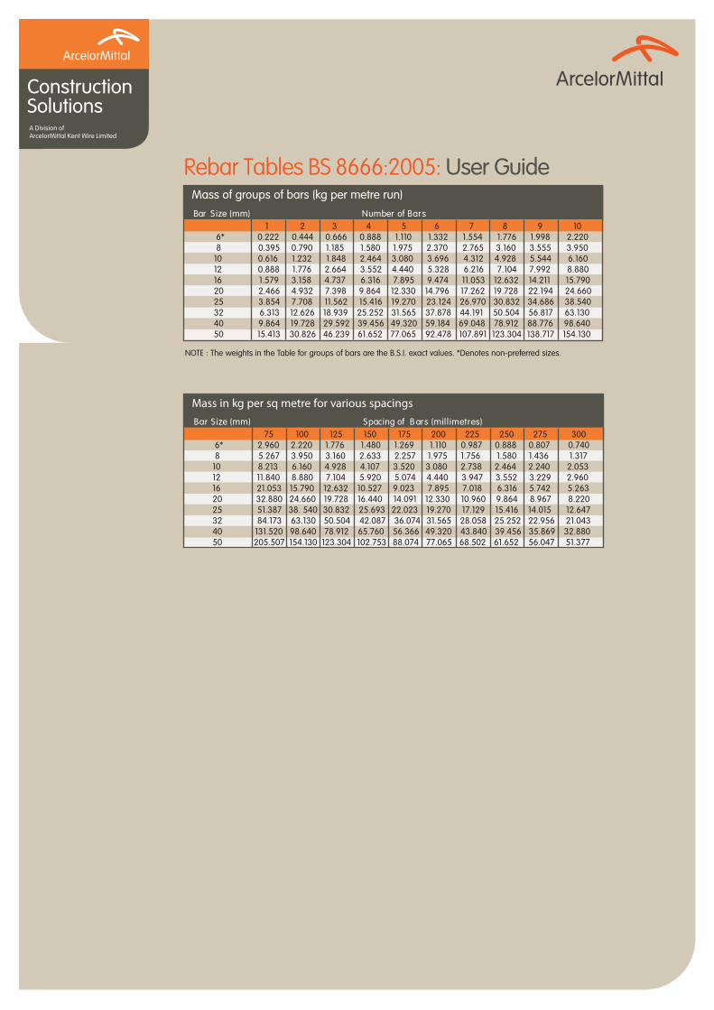
NOTE : The above Tables have been calculated to three significant figures according to the B.S.I. recommendations. * Denotes non-preferred sizes.
sraB fo gnicapS)mm( eziS raB
Chatham Reinforcement Solutions

Rebar Tables BS 8666:2005: User Guide
Construction SolutionsA Division ofArcelorMittal Kent Wire Limited
BS 8110 Ultimate anchorage bond lengths and lap lengths C20-30Bar size
8 10 12 16 20 25 32 40 50Concrete strength class C20/25
Concrete strength class C25/30
BS 8110 Ultimate anchorage bond lengths and lap lengths C28-40Bar size
8 10 12 16 20 25 32 40 50Concrete strength class C28/35
Concrete strength class C32/40
EC2 Ultimate anchorage bond lengths and lap lengthsmecrofnieR ,noisnet ni tnemecrofnieRBond
conditionent
,retemaid rab φ (mm) in compression
NOTES1. Cover to all sides and distance between bars ˜25 mm (i.e. α2 < 1)2. α1 = α3 = α4 = α5 = 1.03. Design stress has been taken as 435 MPa. Where the design stress in the bar at the
position from the where the anchorage is measured, σsd, is less than 435 the figures in this table can be factored by σsd/435
4. The anchorage and lap lengths have been rounded up to the nearest 10 mm5. Where all the bars are lapped in one location, increase the lap lengths for ‘Half the bars
lapped in one location’ by a factor of 1.076. The figures in this table have been prepared for concrete class C25/30; the following factors
may be used for other concrete classes

Rebar Tables BS 8666:2005: User Guide
Construction SolutionsA Division ofArcelorMittal Kent Wire Limited
Minimum overall depth of various U-bars
Fabric to BS 4483 – Preferred meshes in stock size sheets 4.8m long 2.4m wideTromboneHook
AB 4 ∅
fy = 500MPAMinimum mandrel diameter:for φ ˜16mm for φ >16mm Mandrel dia. = 4φMandrel dia. = 7 φ
5∅
Mandrel dia.Mandrel dia.
5∅
(B)
(C)≥5d
Rebar Tables BS 8666:2005: User Guide
Construction SolutionsA Division ofArcelorMittal Kent Wire Limited
Mass of groups of bars (kg per metre run)sraB fo rebmuN)mm( eziS raB
Mass in kg per sq metre for various spacings)sertemillim( sraB fo gnicapS)mm( eziS raB


![Untitled-1 [thamesreinforcements.com]thamesreinforcements.com/Website Content/Shape... · processing steel reinforcement to BS 8666 and BS 4466; CARES-approved for the ... (P13 and](https://img.pdfslide.us/doc/110x75/5b83c19b7f8b9a47588dde46/untitled-1-contentshape-processing-steel-reinforcement-to-bs-8666-and.jpg)