Embed Size (px)
Citation preview
5110 Roanoke Place, Suite 101, College Park, Maryland 20740 | Phone: (301) 474-0607 | Fax: (866) 247-9457 | www.dfrsolutions.com
Reballed Ball Grid Array Reliability Under Shock and
Vibration
Joelle Arnold Dr. Nathan Blattau
5110 Roanoke Place, Suite 101, College Park, Maryland 20740 | Phone: (301) 474-0607 | Fax: (866) 247-9457 | www.dfrsolutions.com
Introduction
The electronics assembly market has experienced a material shift from lead (Pb) based solders to Pb-free solders. This is a result of the widespread adoption of Reduction of Hazardous Substances (RoHS) legislation and practices in commercial industry. As a result, it is becoming increasingly difficult to procure commercial off-the-shelf (COTS) components with tin-lead (SnPb) solder balls or finish. There are essentially three responses to the scarcity of acceptable SnPb parts: custom order, post process or adapt. Custom ordering parts with SnPb finishes negates the benefits of COTS based acquisition, however, has a reduced reliability risk because the material and processes are known. Reprocessing parts once in house saves money because the parts are COTS, but expends money and resources by performing post processing on them. Additionally, the additional touch labor and handling increases the risk of damaging the part. Finally, adapting to Pb-free finishes is the preferred long term approach because it preserves the cost benefits of using COTS parts and does not require post processing. It is the riskiest approach due to the lack of historical data. This report is focused on reballing Ball Grid Array (BGA) parts from tin-silver-copper (SAC305) solder to SnPb eutectic solder. This is an excellent interim approach prior to wholesale adoption of Pb-free parts and processes. It is important to understand the reliability risks associated with the reballing procedure, particularly as it relates to thermal cycling, shock and vibration environments. Three major efforts were undertaken to answer these concerns. First, a survey of reballing vendors was performed to better understand the process and variables associated with that industry. The results of that survey were used to down-select to five vendors that were used for the physical testing portion of this effort. A survey of industry users of reballing services was also performed. Finally, physical testing consisting of thermal cycling, shock, and vibration was performed. The physical testing was performed on parts from five different reballing vendors as well as native SnPb parts and native SAC305 parts.
Survey Results
A survey of pertinent questions for reballers was developed after conferring with technical experts from multiple possible reballers. The questions focused on five key categories: Experience, Technical Aptitude, Capacity, Inspection and Qualification. In all categories, there were questions which required a certain minimum answer to be considered for use. Other questions assessed the position of the reballer within the range of industry standards. Reballing companies were ranked in each category to determine which reballers would provide a cross section of the available expertise, technologies, capacities, and detail of inspection and process control. A matching survey was constructed for customers of reballers to correlate results and forecast future trends. The most common reballed components, are small lots of plastic BGAs of a size between 10mm and 20mm square with a 0.8mm pitch. DfR selected a test component matching these specifications: each reballer was responsible for 150 plastic BGAs of 15mm square, 0.8mm pitch. Responses to questions regarding customer’s experiences with reballers were often mirrored in the process of the study. Most customers receive their reballed parts within 1-3 weeks, as did DfR. Very few defects were found, likely due to the fact that the reballers knew the reballed components were going to be closely inspected in numerous ways. The most glaring defect, a missing solder ball, is listed by those surveyed as a defect that is observed occasionally. Customers would like to see improvement in most
5110 Roanoke Place, Suite 101, College Park, Maryland 20740 | Phone: (301) 474-0607 | Fax: (866) 247-9457 | www.dfrsolutions.com
areas, but the primary areas that need the most improvement is technical capability and the ability to provide reliability data.
Test Vehicle
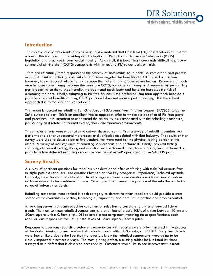
The test articles consisted of a test board populated with 208 I/O BGAs. The test coupons were designed by DfR Solutions, and are multi-purpose and facilitate mechanical shock and vibration testing. They are also capable of board level power cycling through the use of internal heater traces in layers 2 and 3. The traces allow integration of the test boards into the proprietary Therminator thermal cycling system. The top surface of the board is designed to allow continuous monitoring of 20 daisy chained 208 I/O
BGAs, Figure 1. The boards are 7” by 3.5” by 0.062” thick, FR408 (Tg=170°C) and four layers thick. The surface finish for the Phase I boards is Organic Solderability Preservative (OSP).
Figure 1: Top layer of the test board
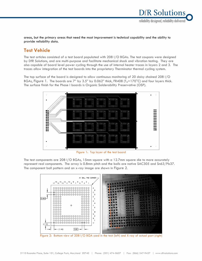
The test components are 208 I/O BGAs, 15mm square with a 12.7mm square die to more accurately represent real components. The array is 0.8mm pitch and the balls are native SAC305 and Sn63/Pb37.
The component ball pattern and an x-ray image are shown in Figure 2.
Figure 2: Bottom view of 208 I/O BGA used in the test (left) and X-ray of actual part (right)
5110 Roanoke Place, Suite 101, College Park, Maryland 20740 | Phone: (301) 474-0607 | Fax: (866) 247-9457 | www.dfrsolutions.com
The boards were assembled by a contract assembler company, Engent (www.engentaat.com). The solders were commercially available No-Clean Sn96.5/Ag3.0/Cu0.5 paste and No-Clean Sn63/Pb37 paste for the SAC305 and SnPb boards respectively. The printing was performed on a Siemens SP500 screen printer using a 5 mil stencil thickness and steel blades. A Siemens F5 placement machine was used for placement of components. The reflow was done in a Siemens RP33S reflow oven in atmosphere. Peak temperature for the Pb-free reflow was 240°C; for the SnPb maximum reflow temperature was 228°C.
Preliminary X-Ray Inspection
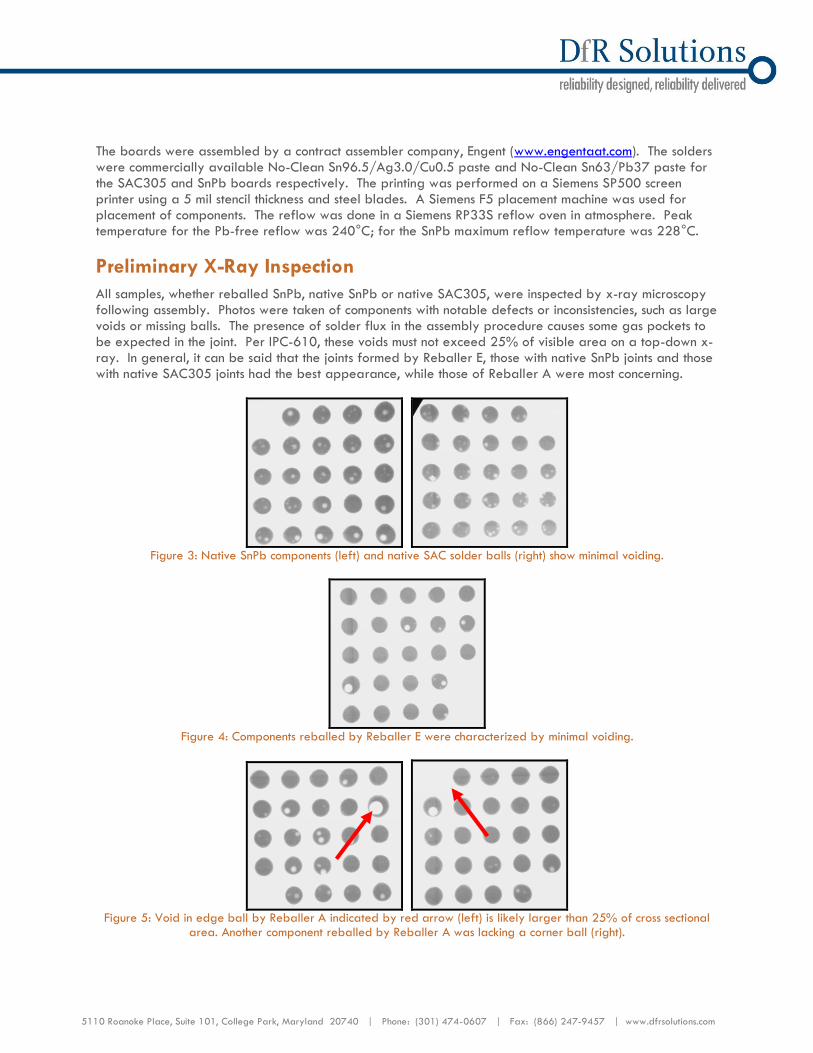
All samples, whether reballed SnPb, native SnPb or native SAC305, were inspected by x-ray microscopy following assembly. Photos were taken of components with notable defects or inconsistencies, such as large voids or missing balls. The presence of solder flux in the assembly procedure causes some gas pockets to be expected in the joint. Per IPC-610, these voids must not exceed 25% of visible area on a top-down x-ray. In general, it can be said that the joints formed by Reballer E, those with native SnPb joints and those with native SAC305 joints had the best appearance, while those of Reballer A were most concerning.
Figure 3: Native SnPb components (left) and native SAC solder balls (right) show minimal voiding.
Figure 4: Components reballed by Reballer E were characterized by minimal voiding.
Figure 5: Void in edge ball by Reballer A indicated by red arrow (left) is likely larger than 25% of cross sectional
area. Another component reballed by Reballer A was lacking a corner ball (right).
5110 Roanoke Place, Suite 101, College Park, Maryland 20740 | Phone: (301) 474-0607 | Fax: (866) 247-9457 | www.dfrsolutions.com
Cross Section Inspection
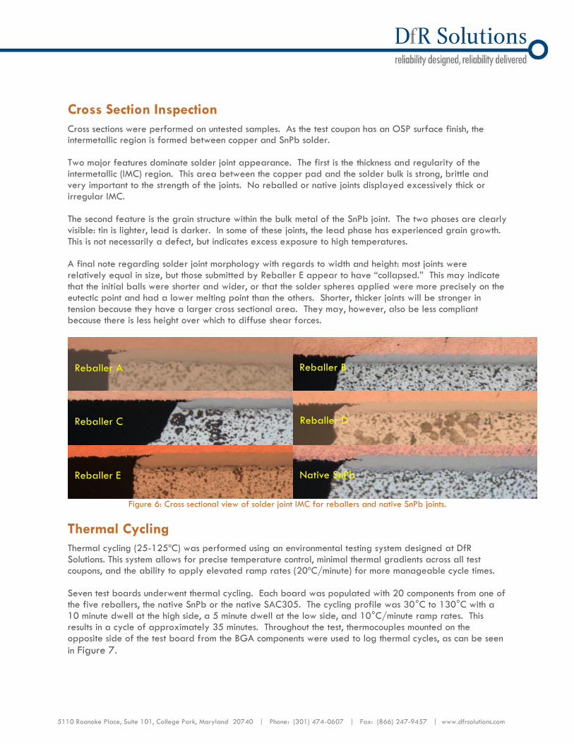
Cross sections were performed on untested samples. As the test coupon has an OSP surface finish, the intermetallic region is formed between copper and SnPb solder. Two major features dominate solder joint appearance. The first is the thickness and regularity of the intermetallic (IMC) region. This area between the copper pad and the solder bulk is strong, brittle and very important to the strength of the joints. No reballed or native joints displayed excessively thick or irregular IMC. The second feature is the grain structure within the bulk metal of the SnPb joint. The two phases are clearly visible: tin is lighter, lead is darker. In some of these joints, the lead phase has experienced grain growth. This is not necessarily a defect, but indicates excess exposure to high temperatures. A final note regarding solder joint morphology with regards to width and height: most joints were relatively equal in size, but those submitted by Reballer E appear to have “collapsed.” This may indicate that the initial balls were shorter and wider, or that the solder spheres applied were more precisely on the eutectic point and had a lower melting point than the others. Shorter, thicker joints will be stronger in tension because they have a larger cross sectional area. They may, however, also be less compliant because there is less height over which to diffuse shear forces.
Figure 6: Cross sectional view of solder joint IMC for reballers and native SnPb joints.
Thermal Cycling
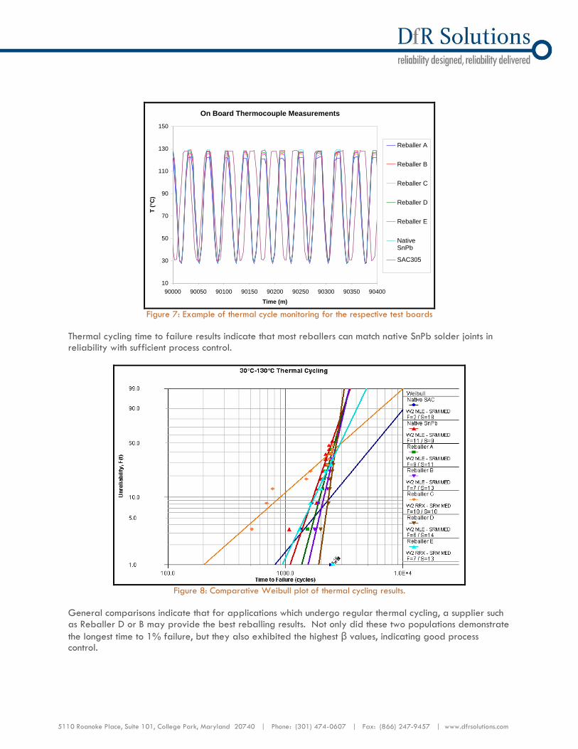
Thermal cycling (25-125ºC) was performed using an environmental testing system designed at DfR Solutions. This system allows for precise temperature control, minimal thermal gradients across all test coupons, and the ability to apply elevated ramp rates (20ºC/minute) for more manageable cycle times. Seven test boards underwent thermal cycling. Each board was populated with 20 components from one of the five reballers, the native SnPb or the native SAC305. The cycling profile was 30°C to 130°C with a 10 minute dwell at the high side, a 5 minute dwell at the low side, and 10°C/minute ramp rates. This results in a cycle of approximately 35 minutes. Throughout the test, thermocouples mounted on the opposite side of the test board from the BGA components were used to log thermal cycles, as can be seen
in Figure 7.
Reballer C
Reballer B
Reballer D
Reballer A
Reballer E Native SnPb
5110 Roanoke Place, Suite 101, College Park, Maryland 20740 | Phone: (301) 474-0607 | Fax: (866) 247-9457 | www.dfrsolutions.com
On Board Thermocouple Measurements
10
30
50
70
90
110
130
150
90000 90050 90100 90150 90200 90250 90300 90350 90400
Time (m)
T (
°C)
Reballer A
Reballer B
Reballer C
Reballer D
Reballer E
NativeSnPb
SAC305
Figure 7: Example of thermal cycle monitoring for the respective test boards
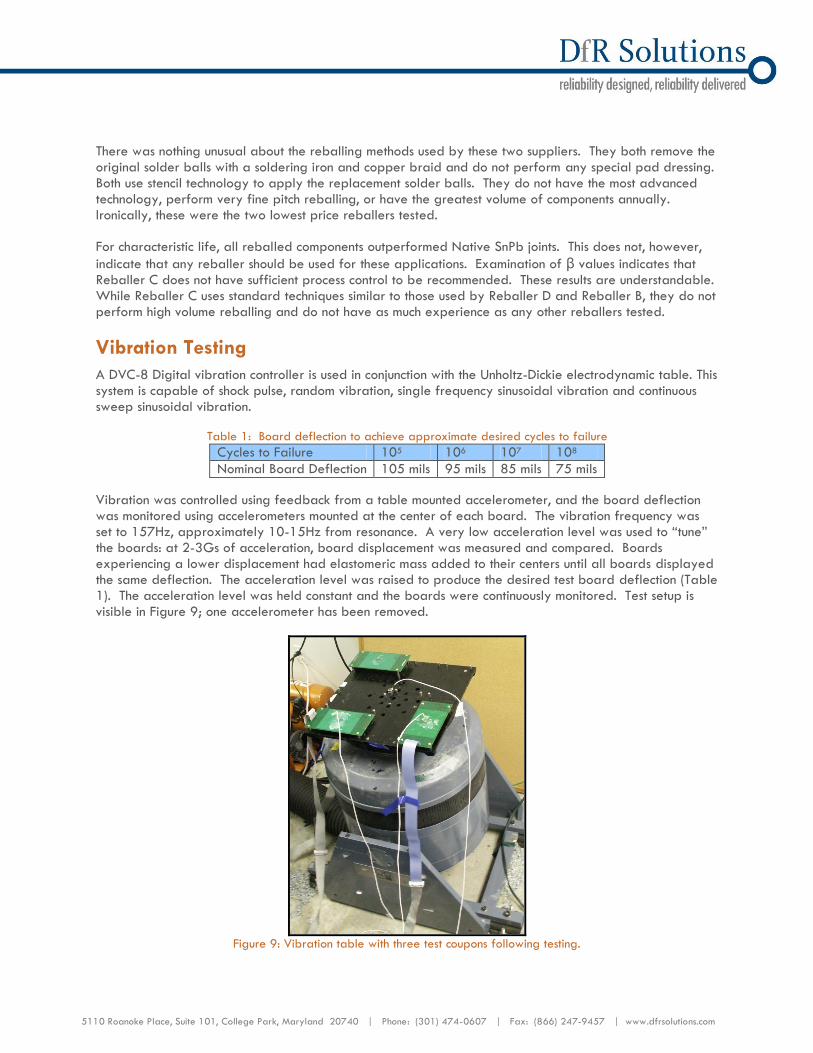
Thermal cycling time to failure results indicate that most reballers can match native SnPb solder joints in reliability with sufficient process control.
Figure 8: Comparative Weibull plot of thermal cycling results.
General comparisons indicate that for applications which undergo regular thermal cycling, a supplier such as Reballer D or B may provide the best reballing results. Not only did these two populations demonstrate
the longest time to 1% failure, but they also exhibited the highest β values, indicating good process control.
5110 Roanoke Place, Suite 101, College Park, Maryland 20740 | Phone: (301) 474-0607 | Fax: (866) 247-9457 | www.dfrsolutions.com
There was nothing unusual about the reballing methods used by these two suppliers. They both remove the original solder balls with a soldering iron and copper braid and do not perform any special pad dressing. Both use stencil technology to apply the replacement solder balls. They do not have the most advanced technology, perform very fine pitch reballing, or have the greatest volume of components annually. Ironically, these were the two lowest price reballers tested. For characteristic life, all reballed components outperformed Native SnPb joints. This does not, however,
indicate that any reballer should be used for these applications. Examination of β values indicates that Reballer C does not have sufficient process control to be recommended. These results are understandable. While Reballer C uses standard techniques similar to those used by Reballer D and Reballer B, they do not perform high volume reballing and do not have as much experience as any other reballers tested.
Vibration Testing
A DVC-8 Digital vibration controller is used in conjunction with the Unholtz-Dickie electrodynamic table. This system is capable of shock pulse, random vibration, single frequency sinusoidal vibration and continuous sweep sinusoidal vibration.
Table 1: Board deflection to achieve approximate desired cycles to failure
Cycles to Failure 105 106 107 108
Nominal Board Deflection 105 mils 95 mils 85 mils 75 mils
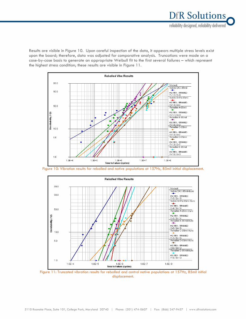
Vibration was controlled using feedback from a table mounted accelerometer, and the board deflection was monitored using accelerometers mounted at the center of each board. The vibration frequency was set to 157Hz, approximately 10-15Hz from resonance. A very low acceleration level was used to “tune” the boards: at 2-3Gs of acceleration, board displacement was measured and compared. Boards experiencing a lower displacement had elastomeric mass added to their centers until all boards displayed the same deflection. The acceleration level was raised to produce the desired test board deflection (Table 1). The acceleration level was held constant and the boards were continuously monitored. Test setup is visible in Figure 9; one accelerometer has been removed.
Figure 9: Vibration table with three test coupons following testing.
5110 Roanoke Place, Suite 101, College Park, Maryland 20740 | Phone: (301) 474-0607 | Fax: (866) 247-9457 | www.dfrsolutions.com
Results are visible in Figure 10. Upon careful inspection of the data, it appears multiple stress levels exist upon the board; therefore, data was adjusted for comparative analysis. Truncations were made on a case-by-case basis to generate an appropriate Weibull fit to the first several failures – which represent the highest stress condition; these results are visible in Figure 11.
Figure 10: Vibration results for reballed and native populations at 157Hz, 85mil initial displacement.
Figure 11: Truncated vibration results for reballed and control native populations at 157Hz, 85mil initial
displacement.
5110 Roanoke Place, Suite 101, College Park, Maryland 20740 | Phone: (301) 474-0607 | Fax: (866) 247-9457 | www.dfrsolutions.com
Matching the reliability of native SnPb joints under vibration is not as straightforward as for thermal cycling. It is clear that the more experienced and capacity reballers (Reballers B, E, and D) can nearly match, match or exceed the performance of the native joints.
The characteristic life (η) of Reballer C’s population exceeds the characteristic life of that of the native joints, but the 1% failure value is nearly an order of magnitude less. This again is likely due to process controls. These results are understandable: while Reballer C uses standard techniques similar to those used by Reballer D and Reballer B, they do not perform high volume reballing and do not have as much experience as any other reballers tested. The results for Reballer A are also not surprising. While their process controls appear to be as tight as any of the higher end reballers (indicated by a comparable shape factor), characteristic life is lowest of any reballers studied. They are a low capacity, moderate experience reballer whose joints exhibited numerous defects during x-ray.
Mechanical Shock Testing
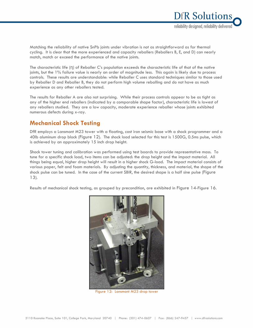
DfR employs a Lansmont M23 tower with a floating, cast iron seismic base with a shock programmer and a
40lb aluminum drop block (Figure 12). The shock load selected for this test is 1500G, 0.5ms pulse, which is achieved by an approximately 15 inch drop height. Shock tower tuning and calibration was performed using test boards to provide representative mass. To tune for a specific shock load, two items can be adjusted: the drop height and the impact material. All things being equal, higher drop height will result in a higher shock G-load. The impact material consists of various paper, felt and foam materials. By adjusting the quantity, thickness, and material, the shape of the
shock pulse can be tuned. In the case of the current SBIR, the desired shape is a half sine pulse (Figure 13).
Results of mechanical shock testing, as grouped by precondition, are exhibited in Figure 14-Figure 16.
Figure 12: Lansmont M23 drop tower

5110 Roanoke Place, Suite 101, College Park, Maryland 20740 | Phone: (301) 474-0607 | Fax: (866) 247-9457 | www.dfrsolutions.com
Figure 13: 1500G 0.5ms pulse
Figure 14: Mechanical shock reliability of non-preconditioned reballed components.
5110 Roanoke Place, Suite 101, College Park, Maryland 20740 | Phone: (301) 474-0607 | Fax: (866) 247-9457 | www.dfrsolutions.com
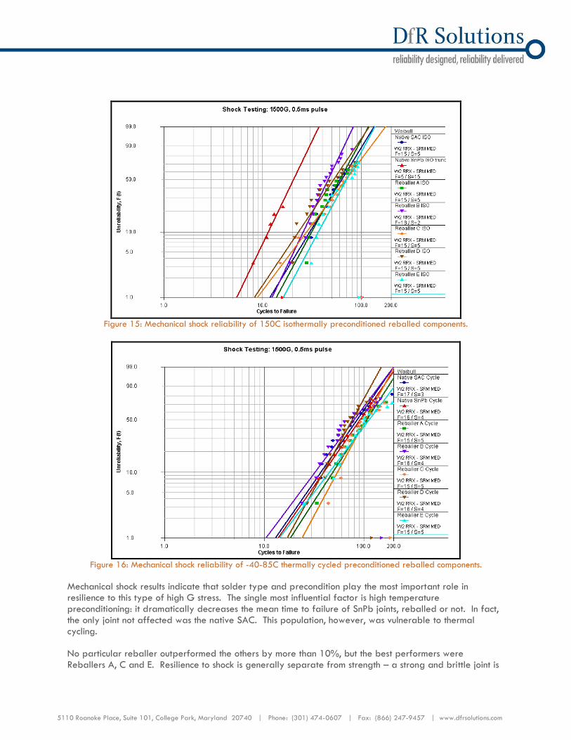
Figure 15: Mechanical shock reliability of 150C isothermally preconditioned reballed components.
Figure 16: Mechanical shock reliability of -40-85C thermally cycled preconditioned reballed components.
Mechanical shock results indicate that solder type and precondition play the most important role in resilience to this type of high G stress. The single most influential factor is high temperature preconditioning: it dramatically decreases the mean time to failure of SnPb joints, reballed or not. In fact, the only joint not affected was the native SAC. This population, however, was vulnerable to thermal cycling. No particular reballer outperformed the others by more than 10%, but the best performers were Reballers A, C and E. Resilience to shock is generally separate from strength – a strong and brittle joint is

5110 Roanoke Place, Suite 101, College Park, Maryland 20740 | Phone: (301) 474-0607 | Fax: (866) 247-9457 | www.dfrsolutions.com
less likely to survive the high energy impacts. The increased compliance of these joints may be due to the presence of voids within the solder joints. In the case of Reballer E, which had fewer voids than Reballers A and C, a thinner intermetallic layer could have the same effect.
Looking Forward
The adoption of RoHS by the European Union has driven the electronics industry to adopt Pb-free solders. This wide spread adoption dramatically reduces the number of components available with SnPb solder finishes. In the present and future, requiring Pb based components and assembly will be a significant cost driver for high reliability systems. It will soon be impossible to procure any COTS components with a SnPb compatible material system. This will quickly drive the costs associated with custom production runs or component remanufacture to ensure material compatibility with existing SnPb systems. Until transition to Pb-free systems is complete, many manufacturers are turning to reballing as an interim solution. Reballing, however, can be a challenging procedure, and may negate the reliability benefits of maintaining a SnPb assembly. This assessment determined that no “special technique” is superior, however, reballers who produce higher volume and have more experience generate the most consistent and reliable parts by all tests. Some of these high volume reballers do use special techniques to assist in throughput.