Embed Size (px)
Citation preview

Control Theory and Informatics www.iiste.org
ISSN 2224-5774 (Paper) ISSN 2225-0492 (Online)
Vol.5, No.3, 2015
26
Rearranged SVPWM Algorithm for Neutral Point Clamped
3-Level Inverter Encouraged DTC-IM Drive
Yelem.Srikanth Power Electronics,Rgmcet,Nandyal.
E-mail: [email protected]
Abstract
In this paper, an improved space vector beat width tweak (SVPWM) strategy has been created for three stage three-level voltage source inverter bolstered to direct torque controlled (DTC) actuation engine drive. The space vector outline of three-level inverter is streamlined into two-level inverter. So the choice of exchanging arrangements is done as traditional two-level SVPWM system. Where in ordinary direct torque control (CDTC), the stator flux and torque are straightforwardly controlled by the determination of ideal exchanging modes. The choice is made to limit the flux and torque slips in comparing hysteresis groups. Notwithstanding its quick torque reaction, it has more flux, torque and current swells in consistent state. To beat the swells in relentless state, a space vector based heartbeat width tweak (SVPWM) technique is proposed in this paper. The proposed SVPWM system lessens the computational weight and decreases the aggregate consonant contortion contrasted and 2-level one and the ordinary one too. To fortify the voice reproduction is completed and the relating results are presented. Keywords: SVPWM, DTC 1. Introduction
The beat width balanced voltage source inverters (PWM-VSI) sustained variable rate affectation engine drives have increased more significance in numerous mechanical applications. The development of the field situated control (FOC) acquired a renaissance the field of superior drives. The FOC calculation controls the affectation engine like that of an independently energized dc engine [1]. In any case, the intricacy included in FOC calculation is all the more because of reference casing changes. To lessen the many-sided quality in the calculation and to accomplish decoupled control, another torque control methodology has proposed in [2]. A definite examination in the middle of FOC and DTC has been displayed in [3] and reasoned that DTC gives great element reaction when contrasted and FOC. In spite of the fact that DTC gives great element execution, it gives extensive consistent state swells in torque, flux and streams. To lessen the swells, discrete space vector balance (DSVM) calculation has proposed in [4]. In any case, the established DTC and DSVM based DTC display variable exchanging recurrence operation of the inverter. To lessen the swells further, these days, the multilevel inverters are getting to be mainstream A diode cinched three-level inverter has proposed in [5]. Three-level inverter based DTC has proposed in [6], which utilizes the changing tables to create the gating beats of the inverter. To accomplish the consistent exchanging recurrence operation and to diminish the consonant contortion different heartbeat width balance calculations have been produced. An itemized study on different PWM calculations is given in [7]. Among the different PWM calculations, the space vector beat width adjustment (SVPWM) is famous because of its various favorable circumstances [8]. To accomplish the consistent exchanging recurrence operation, SVPWM calculation is utilized for DTC as a part of [9]. As the quantity of levels increments in a multilevel inverter, the many-sided quality included in the SVPWM calculation likewise increments. To decrease the multifaceted nature, an improved SVPWM calculation has been proposed for three-level inverter in [10]. This paper introduces a streamlined SVPWM calculation for three-level inverter sustained direct torque controlled prompting engine drives. The proposed calculation utilizes the idea of SVPWM calculation which is utilized for two-level inverter. II. Conventional DTC
The square graph representation of CDTC is indicated in Fig 1. The stator streams and DC transport voltage are examined at each testing inverter of time. Speed, torque, stator flux and flux point are assessed in the versatile engine show by considering voltages, streams to the drive. The evaluated torque and flux are contrasted and their comparing hysteresis comparators separately. The quantity of division where the stator flux space vector is found and the yields of hysteresis comparators are encouraged to ideal changing table to choose a proper voltage vectors. At that point this voltage space vector is connected to inverter. III. Space Vector PWM Algorithm
Among these voltage vectors, V1 to V6 vectors are known as dynamic voltage vectors or dynamic states and the staying two vectors are known as zero states or zero voltage vectors. The reference voltage space vector or test, which is as indicated in Fig.2 speaks to the relating to the wanted estimation of the basic segments for the yield

Control Theory and Informatics www.iiste.org
ISSN 2224-5774 (Paper) ISSN 2225-0492 (Online)
Vol.5, No.3, 2015
27
stage voltages. In the space vector approach this can be built in a normal sense. Vref is inspected at equivalent interims of time, Ts alluded to as examining time period. Distinctive voltage vectors that can be created by the inverter are connected over diverse time spans with in an examining time period such that the normal vector delivered over the inspecting time period is equivalent to the examined estimation of the Vref , both regarding size and point. It has been set up that the vectors to be utilized to produce any example are the zero voltage vectors and the two dynamic voltage vectors framing the limit of the area in which the specimen lies. As every one of the six divisions are symmetrical, the exchange is restricted to the first division just. For the obliged reference voltage vector, the dynamic and zero voltage vectors times can be ascertained as in (1), (2) and (3).
Fig. 1 Block Diagram of CDTC
Fig. 2 Possible voltage space vectors
(1)
(2)
(3) where Mi is the regulation record and characterized as in [7]. In the SVPWM calculation, the aggregate zero voltage vector time is similarly partitioned in the middle of V0 and V7 and disseminated symmetrically toward the begin and end of the every examining time period. Consequently, SVPWM utilizes 0127-7210 in division I, 0327-7230 in part II etc.
IV. Proposed Simplified SVPWM Algorithm For Three-Level Inverter
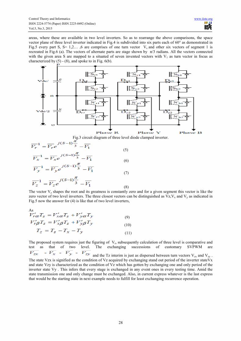
A three level diode braced inverter circuit outline is indicated in Fig.3. The space vectors connected with in the three level inverter on d-q plane are indicated in Fig.3. In SVPWM approach, the reference vector Vr is examined at consistent interim of time Ts. The tested reference vector is approximated by time averaging the closest three vectors Vx,Vy and Vz as VrTs= VxTx+VyTy+VzTz (4) where Tx , Ty and Tz are the stay times of Vx,Vy, andVz separately. The zero vectors are not present in all the
Control Theory and Informatics www.iiste.org
ISSN 2224-5774 (Paper) ISSN 2225-0492 (Online)
Vol.5, No.3, 2015
28
areas, where these are available in two level inverters. So as to rearrange the above comparisons, the space vector plane of three level inverter indicated in Fig.4 is subdivided into six parts each of 60° as demonstrated in Fig.5 every part S, S= 1,2… ,6 are comprises of one turn vector Vs and other six vectors of segment 1 is recreated in Fig.6 (a). The vectors of alternate parts are stage shown by π/3 radians. All the vectors connected with the given area S are mapped to a situated of seven invented vectors with V1 as turn vector in focus as characterized by (5) - (8), and spoke to in Fig. 6(b).
Fig.3 circuit diagram of three level diode clamped inverter.
(5)
(6)
(7)
(8) The vector Vz shapes the root and its greatness is constantly zero and for a given segment this vector is like the zero vector of two level inverters. The three closest vectors can be distinguished as Vz,Vx and Vy as indicated in Fig.5 now the answer for (4) is like that of two level inverters, As
(9)
(10)
(11) The proposed system requires just the figuring of Vr, subsequently calculation of three level is comparative and test as that of two level. The exchanging successions of customary SVPWM are
and the Tz interim is just as dispersed between turn vectors Vzx and Vzy . The state Vzx is signified as the condition of Vz acquired by exchanging stand out period of the inverter stateVx and state Vzy is characterized as the condition of Vz which has gotten by exchanging one and only period of the inverter state Vy . This infers that every stage is exchanged in any event ones in every testing time. Amid the state transmission one and only change must be exchanged. Also, in current express whatever is the last express that would be the starting state in next example needs to fulfill for least exchanging recurrence operation.

Control Theory and Informatics www.iiste.org
ISSN 2224-5774 (Paper) ISSN 2225-0492 (Online)
Vol.5, No.3, 2015
29
Fig.4 Space vector diagram of three-level inverter.
V. Proposed Simplified SVPWM Algorithm For Three-Level Inverter
The square outline of proposed DTC is indicated in Fig.7. In every testing time period, the flux lapses are to be minimized which could be brought about by ψs and ψs .And summation of genuine rotor speed ωr and extra slip speed ωsl will deliver the velocity of ψs .The suitable reference voltage space vectors delivered by reference voltage vector adding machine piece are
(12)
(13)
Fig. 5 (a) vectors of Sector 1 (b) Mapping of sector 1 to fictitious vector
Fig.6 Block diagram of proposed DTC drive.
VI. Simulation Results And Discussions
By using Matlab/Simulink, the advantage of SVPWM application as a numerical simulation has been carried out with fixed step size of 1µs in ode4 (runge-kutta) method. A 3-phase, 4 pole, 4kW, 1200rpm induction motor with parameters of Rs = 7.83Ω, Rr = 7.55Ω, Ls = Lr = 0.4751H, Lm=0.4535 and J = 0.089Kg.m2 are considered. The enduring state plots of Conventional DTC are demonstrated in Fig. 7-Fig. 8, from which, it can be watched that the Conventional DTC gives huge consistent state swells and more consonant contortion. To decrease the swells,

Control Theory and Informatics www.iiste.org
ISSN 2224-5774 (Paper) ISSN 2225-0492 (Online)
Vol.5, No.3, 2015
30
SVPWM calculation is utilized for 2-level inverter. The reenactment results for SVPWM calculation based 2-level inverter encouraged DTC-IM drive are demonstrated in Fig. 9 - Fig. 10. The recreation consequences of proposed streamlined SVPWM calculation based 3-level inverter bolstered DTC-IM drive are shown in Fig. 11 - Fig. 16.
Fig 7 steady state plots of speed, torque, stator currents and stator flux for CDTC based IM drive at 1200 rpm.and Fig.8 Harmonic Spectrum of stator current along with THD.
Fig. 9 Simulation results of 2-level SVPWM based DTC: steady-state plots at 1200 rpm. And Fig. 10 Harmonic Spectrum of stator current along with THD for 2-Level SVPWM based DTC-IM drive.
Fig. 11 Starting transients in speed, torque, currents and flux for simplified SVPWM algorithm based 3-level inverter fed DTC-IM. And Fig. 12 Steady state plots of speed, torque, currents and flux for simplified SVPWM algorithm based 3-level inverter fed DTC-IM.

Control Theory and Informatics www.iiste.org
ISSN 2224-5774 (Paper) ISSN 2225-0492 (Online)
Vol.5, No.3, 2015
31
Fig. 13 Harmonic spectra of steady state line current for simplified SVPWM algorithm based 3-level inverter fed DTC-IM. And Fig. 14 transients during step change in load for simplified SVPWM algorithm based 3-level inverter fed DTC-IM: a 30 N-m load is applied at 0.5 sec.
Fig. 15 Phase and line voltages during a step change in load for simplified SVPWM algorithm based 3-level inverter fed DTC-IM: a 30 N-m load is applied at 0.5 sec. and Fig. 16 Transients in speed, torque, currents and flux during speed reversal for simplified SVPWM algorithm based 3-level inverter fed DTC-IM (speed is changed from 1200 rpm to -1200 rpm at 0.7 s)
Fig. 17Transients in speed, torque, currents and flux during speed reversal for simplified SVPWM algorithm based 3-level inverter fed DTC-IM (speed is changed from -1200 rpm to +1200 rpm at 1.35 s) and Fig.18 stator flux for simplified SVPWM algorithm based 3-level inverter fed induction motor drive.

Control Theory and Informatics www.iiste.org
ISSN 2224-5774 (Paper) ISSN 2225-0492 (Online)
Vol.5, No.3, 2015
32
VII. Conclusions In this paper, a rearranged SVPWM calculation is introduced for three-stage three-level inverter encouraged DTC drive. The proposed calculation creates the changing heartbeats like a two-level inverter based SVPWM calculation. Along these lines, the proposed calculation diminishes the intricacy included in the current PWM calculations. To approve the proposed PWM calculation, numerical reproduction studies have been completed and results are exhibited. From the reproduction results, it can be inferred that the three-level inverter nourished DTC drive gives lessened relentless state swells and consonant mutilation. References
[1] F. Blaschke “The principle of field orientation as applied to the new trans vector closed loop control system for rotating-field machines," Siemens Review, 1972, pp 217-220. [2] Isao Takahashi and Toshihiko Noguchi, “A new quick-response and high-efficiency control strategy of an induction motor,” IEEE Trans. Ind. Applicat., vol. IA-22, no.5, Sep/Oct 1986, pp. 820-827. [3] Domenico Casadei, Francesco Profumo, Giovanni Serra, and Angelo Tani, “FOC and DTC: Two Viable Schemes for Induction Motors Torque Control” IEEE Trans. Power Electron., vol. 17, no.5, Sep, 2002, pp. 779-787. [4] D. Casadei, G. Serra and A. Tani, “Implementation of a direct torque control algorithm for induction motors based on discrete space vector modulation” IEEE Trans. Power Electron., vol.15, no.4, Jul 2000, pp.769-777. [5] Nabae, A., Takahashi, I., and Akagi, H, "A neutral-point clamped PWM inverter’, IEEE-Trans. Ind. Appl., 1981, 17, (5), pp.518-523. [6] A. Damiano, G. Gatto, I. Marongiu and A. Perfetto, “An improved multilevel DTC drive” in IEEE proc.
PESC, 2001, pp.1452-1457. [7] Joachim Holtz, “Pulsewidth modulation – A survey” IEEE Trans. Ind. Electron.., vol. 39, no. 5, Dec 1992, pp. 410-420. [8] Heinz Willi Vander Broeck, Hnas-Christoph Skudelny and Georg Viktor Stanke, “Analysis and realization of a pulsewidth modulator based on voltage space vectors” IEEE Trans. Ind. Applicat., vol. 24, no. 1, Jan/Feb 1988, pp. 142-150. [9] Lixin Tang, L. Zhong, M.F. Rahman and Y.Hu, “An investigation of a modified direct torque control strategy for flux and torque ripple reduction for induction machine drive system with fixed switching frequency” in Proc
IEEE Ind. Appl. Conf, 2002, pp. 837-844. [10] Abdul Rahiman Beig, G. Narayana, V.T. Ranganathan, “Modified SVPWM Algorithm for Three Level VSI With Synchronized and Symmetrical Waveforms”, IEEE Trans. Ind. Elect., Vol. 54, No. 1, Feb. 2007, pp 486-494.

The IISTE is a pioneer in the Open-Access hosting service and academic event management.
The aim of the firm is Accelerating Global Knowledge Sharing.
More information about the firm can be found on the homepage:
http://www.iiste.org
CALL FOR JOURNAL PAPERS
There are more than 30 peer-reviewed academic journals hosted under the hosting platform.
Prospective authors of journals can find the submission instruction on the following
page: http://www.iiste.org/journals/ All the journals articles are available online to the
readers all over the world without financial, legal, or technical barriers other than those
inseparable from gaining access to the internet itself. Paper version of the journals is also
available upon request of readers and authors.
MORE RESOURCES
Book publication information: http://www.iiste.org/book/
Academic conference: http://www.iiste.org/conference/upcoming-conferences-call-for-paper/
IISTE Knowledge Sharing Partners
EBSCO, Index Copernicus, Ulrich's Periodicals Directory, JournalTOCS, PKP Open
Archives Harvester, Bielefeld Academic Search Engine, Elektronische Zeitschriftenbibliothek
EZB, Open J-Gate, OCLC WorldCat, Universe Digtial Library , NewJour, Google Scholar


![A Comparative Study and Experimental Investigation of ...SVPWM, who contributed a lot in PWM methods [4-9]. In comparison between SPWM and SVPWM, SVPWM results excellent dc bus utilization](https://img.pdfslide.us/doc/110x75/61264de56b3f754d585eb80a/a-comparative-study-and-experimental-investigation-of-svpwm-who-contributed.jpg)