Embed Size (px)
Citation preview

REAR AXLE 3-1
GROUP 3
REAR AXLE
CONTENTS Page
Axle Drive Shafts , . . . 3 Data and Specifications 1 Differential Carrier Assembly Installation 14 Differential Carrier Disassembly 5 Differential Carrier Removal 5 Differential Case Assembly • • -8 Differential Case Assembly Installation. 16 Differential Cleaning and Inspection 7 Drive Gear and Pinion Backlash 14 Gear Tooth Contact Pattern 15 Pinion Bearing Cup Installation 9 Pinion Carrier Pre-Load—Depth of Mesh—Installation Using Tool C-758 (Model SC-l) 9 Pinion Bearing Pre-Load and Pinion Setting (Models SC-2, SC-3, SY-1) Using Tool C-758-D-3. 12 Pinion Bearing Pre-Load and Pinion Setting (Without Using Tool C-758) 13 Welding Rear Axle Housing 16
SURE-GRIP DIFFERENTIAL
Service Diagnosis Sure-Grip Differential Identification. Sure-Grip Lubrication Sure-Grip Removal and Installation.
DATA AND SPECIFICATIONS MODELS SC-l, SC-2, SC-3, SY-1
Type Semi-Floating Gear Type Hypoid Ring Gear Diameter 8.75 inch Pinion Bearing - Tapered Roller (2) Drive Pinion Bearing Pre-Load. 20-30 in. lbs. without seal Adjustment • - • Shim Pack Differential Bearings Tapered Roller (2) Differential Bearing A d j u s t m e n t . . . . . . . . . . . . . . . . . . . . . . . . . . . . . . . . . . . Threaded Adjuster Drive Gear and Pinion Serviced in Matched Sets only Drive Gear Runout .005 inch (Maximum) Drive Gear and Pinion Adjustment Select Washer Drive Gear and Pinion B a c k l a s h . . . . . . . . . . . . . . . . . . . . . . . . . . . . . . . . . . . .006 to .008 inch Differential Side Gear Clearance. .. .001 to .012 inch Differential Lubricant Capacity. 4 pints Axle Ratio
(Manual Transmission) SC-l 3.58 to 1 (TorqueFlite Transmission) SC-l, SC-2, SC-3, SY-1 2.93 to 1
Wheel Bearing Axle Shaft End Play. .013 to .023 inch

3-2 REAR AXLE
TOHQUE BEFERENCE
(Foot-Pounds)
Axle Shaft N u t s . . . . . . . . . . . . . . . . * 145 (min.)
Brake Support Plate to Housing Mounting Bolt Nuts 30 to 35
Differential Bearing Cap Bolts. 90
Differential Carrier to Axle Housing Bolt Nuts 45
Rear Axle Drive Gear to Case Bolts s. 60
Rear Axle Drive Pinion Companion Flange Nut 240 (min.)
Spring Clip (U-Bolts) Nuts 50
GROUP 3
1EA1 AXLE
The rear axle assembly (Figs. 1 and 2) may be divided into four subassemblies; axle drive shafts with related parts, differential with ring gear, drive pinion with carrier, and the axle housing. I t is not
necessary to remove the entire assembly to service
any of the above parts with the exception of the
axle housing itself.
SHAFT
Fig. 1—Rear Axle {Imperial and Chrysler except Newport)

REAR AXLE 3-3
Fig. 2—Rear Axle (Chrysler Newport SC-l)
SERVICE PROCEDURES
AXLE DRIVE SHAFTS
Removal
(1) Raise the car and remove the rear wheels, hub and drum assembly using puller Tool C-845 or Tool C-319. Do not strike the end of the axle shaft. Use of a knock oif type puller may cause damage to bearings and thrust block.
(2) Block the brake pedal to prevent its being depressed and disconnect the brake lines at the wheel cylinders.
Fig. 3—Removing Axle Drive Shaft and Bearing
(3) Remove the axle drive shaft key and remove the brake support and dust shield using Tool C-745 to protect the outer seal.
(4) Carefully remove the shim pack from each end of the axle housing. Identify each shim pack as to location to aid in reassembly.
(5) Remove the axle shaft and bearing assembly with Tool C-499 (Fig. 3). I f necessary, the bearings may be removed from the axle shafts with bearing puller Tool C-293 and number 13 adaptors (Fig. 4).
(6) Remove the axle shaft inner oil seals with puller Tool C-637 (Fig. 5). Remove the brake dust shield outer seal with Tool C-3565.
Fig. 4—Removing Bearing from Axle Drive Shaft 1. Axle Drive Shaft 2. Tool 3. Bearing

34 REAR AXLE
49x713
Fig. 5—Removing Axle Drive Shaft Inner Seal
Cleaning and Inspection
(1) With mineral spirits or dry cleaning solvent, clean the axle shafts, bearings, cups, shims and shim contacting surfaces as well as the counterbores of the axle housing. With the exception of the bearings, dry all parts with compressed air.
(2) Inspect the bearing cones and cups for brin-nelling or other visible damage. I f either the bearing cone or cup is unfit for further service, always replace both.
(3) Inspect each axle shaft for signs of fatigue, worn or scored oil seal contacting surfaces, wear or accumulated metal deposits on the thrust block end of shaft, damaged threads, or excessively worn splines. Machine surfaces can usually be satisfactorily cleaned. I f abnormal conditions are noted, the shafts should be replaced.
(4) Inspect the shims for distortion or other visible damage. Discard, any shims unfit for further service.
(5) Inspect the shim contacting surfaces of both the brake support and axle housing for burrs. Remove burrs with crocus cloth if possible.
(6) I f Inspection above reveals that replacement of either the axle shafts or bearings are necessary, install new bearings on either the original shaft or the new shaft. Make certain that the bearing and axle shaft contacting surfaces are thoroughly cleaned so the bearing when Installed, bottoms against the shoulder of the axle shaft (tapered portion of bearing must face the axle shaft threads.)
Axle Shaft End Play
Axle shaft preferred end play is .013 to .018 Inch, however, up to .023" is permissible. The end play is necessary because as much as .012 inch end play
Fig. 6—Installing Axle Shaft Inner Oil Seal
may be taken up after operating temperatures are reached during normal operation. The loss of end play occurs because the axle shafts expand (lengthwise) more than the axle housing as the temperatures increase. Less than .013 inch end play can result in a preloaded bearing, under these conditions, causing shorter bearing life.
Axle Drive Shaft End Play
(1) When original axle shafts and/or bearings are used, start the measurement of the shaft end play with the original shim packs, after recording thickness of each. Where either or both the axle shaft and bearing are replaced, use shim packs totaling .040 inch per side. Shims are available in thickness of: .005, .0125, .015 and .030 Inch.
(2) Install the inner oil seals with Tool C-839 (Fig. 6).
(3) Starting at one end of the axle housing, install a .040 inch shim pack on the flange studs.
(4) Working from the same side of the axle housing, lubricate the axle shaft bearing with a wheel bearing lubricant, and Install the axle shaft.
(5) Install the bearing cup with the installing
Fig. 7—Installing Axle Drive Shaft Bearing Cup

REAR AXLE 3-5
Tool C-413 (Fig. 7). Make certain the bearing cup Is driven into the axle housing until the face of the Installing tool bottoms against the shims, not the housing lange. Eemove the tool and Install the brake support, lockwashers and nuts. Torque tighten the nuts 30 to 35 foot-pounds.
(6) Working from the opposite side of the axle housing, lubricate the bearing and install the other axle shaft until i t contacts the axle shaft thrust block.
(7) With a fiber mallet, lightly tap the end of the axle shaft against the thrust block. (This will force the opposite axle shaft bearing into its cup to the fullest extent).
(8) Install the bearing cup with Tool C-413. The bearing cup must be tapped into position until the axle shaft end play just disappears. The bearing cup will protrude slightly beyond the face of the axle housing flange.
(9) While the tool is held firmly against the bearing cup, insert a feeler gauge between the axle housing flange and the face of the tool to measure the clearance.
(10) To obtain .013 to .018 inch axle shaft end play, which is required, add a minimum of .013 inch to whatever the feeler gauge reading is. I t is recommended that end play be held to the .018" limit rather than the low limit. Compare the thickness of this shim pack with the thickness of the opposite pack. I f the difference in the thickness of shim packs exceed .020 inch, divide the difference to center the axle shafts and the thrust block. Equal thickness of shims on both axles shafts is necessary to maintain the centralized position of axle shaft thrust block.
(11) Position the shim packs on the flange studs and drive the cups in until the tool bottoms on the shim pack.
(12) Install a new outer oil seal in the brake support plate with Tool C-3565 with the lip of the seal toward the center of the car.
(13) Insert the sleeve Tool C-745 in the outer seal to protect the seal when the brake support is installed.
(14) Install the dust shield, and brake support. Tighten the attaching nuts 30 to 35 foot-pounds. Install the wheels, hub and drum. The axle shaft key should be flush with the outer end of the hub.
DIFFERENTIAL CARRIER REMOVAL
(1) Remove the axle drive shafts, Paragraph "Axle Drive Shafts."
Fig. 8—Measuring Drive Gear Runout
(2) Disconnect the rear universal joint and drop the propeller shaft.
(3) Remove the lubricant from the axle housing using a suction gun.
(4) Remove the attaching nuts and lift the rear axle carrier assembly from under the car.
CARRIER DISASSEMBLY
Differential Assembly Removal
(1) Mount the carrier in Stand DD-1014 and attach the dial indicator Tool C-430 or C-3339 to the differential carrier flange so the pointer of the indicator squarely contacts the back face of the ring gear (Fig. 8). Make certain there is no end play in the differential side bearings. I f end play is evident, remove the adjuster lock and slightly loosen the bearing cap on the gear tooth side. Tighten the adjuster sufficiently to eliminate the end play.
Fig. 9—Marking Bearing Caps and Adjusting Nuts

3-6 REAR AXLE
(2) Eotate the ring gear several complete revolutions while noting the total indicator reading. This reading must not exceed .005 inch runout. I f the indicator reading exceeds the .005 inch runout, it will be necessary to take a second reading after the ring gear has been removed. This operation Is covered during "Differential Disassembly". Eemove the dial Indicator.
(3) Apply identifying punch marks on the bearing supports of the differential carrier, differential bearing caps, and bearing adjusters for reassembly purposes (Fig. 9).
(4) Eemove each of the differential bearing adjuster lock screws and locks.
(5) With a % inch socket wrench, loosen the bearing cap bolts (one on each side) and back off the bearing adjusters slightly with spanner wrench Tool C-406, to remove the differential case bearing preload. Eemove the bearing cap bolts, caps and bearing adjusters.
(6) Eemove the differential assembly with bearing cups. Make certain that each bearing cup remains with its respective bearing.
Pinion Removal (7) With the companion flange up, hold the flange
with holding Tool C-3281 and remove the pinion shaft nut and belleville washer.
(8) Install the companion flange puller Tool C-452 and remove the flange (Fig. 10).
(9) Install the oil seal puller Tool C-748 by screwing It securely into the pinion oil seal (Fig, 11) and tighten the puller screw to remove the seal.
(10) While holding one hand over the companion flange end of the carrier, invert the carrier in the stand. The oil slinger, front bearing cone shim pack and bearing spacer (where used) will drop from the carrier.
(11) Withdraw the pinion and rear bearing cone from the carrier.
Fig. 10—Removing Companion Flange
Fig. 11—Removing Pinion Bearing Oil Seal
Pinion Rear Bearing Removal
(1) The 1962 Chrysler Newport SC-l rear axle carriers use different adaptors to remove the pinion rear bearing than the carriers on all other 1962 Chrysler and Imperial Models.
When removing the pinion rear bearing (Fig. 12) on a 1962 Chrysler Newport carrier use Tool C-293 and four (4) No. 36 adaptors. On all other 1962 Chrysler and Imperial Models, use Tool C-293 and four (4) No. 37 adaptors.
(2) The pinion bearing cups can be removed from the carrier with a blunt brass drift and hammer.
Differential Case Disassembly
(1) Hold the ring gear in an upright position using brass jaws in a vise. With a % inch socket wrench, remove the ring gear to differential attaching cap screws. The ring gear, attaching screws have left hand threads.
(2) Remove the assembly from the vise, and with a fiber mallet, tap the ring gear off the case.
PLATES
Fig. 12—Removing Bearing From Pinion Shaft

REAR AXLE 3-7
Fig. 13—Measuring Drive Gear Mounting Flange Runout
(3) I f the ring gear runout was found to be more than .005 inch (Paragraph "Carrier Disassembly" (2)) test the case as follows: Install the differential with bearing" cups in the carrier.
(4) Install the bearing caps, attaching bolts and bearing adjusters. Snug the bearing cap bolts down lightly and screw in both adjusters with spanner wrench Tool C-406A.
(5) Tighten the support cap bolts and adjusters sufficiently to prevent any end play in the bearings.
(6) Attach a dial indicator Tool C-430 or C-3339 to the differential carrier flange so the pointer of the indicator squarely contacts the ring gear surface of the differential case flange between the outer edge of the flange and the ring gear bolt holes (Fig. 13).
(7) Rotate the differential several complete revolutions while noting the total indicator reading.
Fig. 14—Measuring Differential Gear Clearance
Fig. 15—Removing Differential Bearings
This reading must not exceed .003 Inch runout. I f the runout Is In excess of .003 Inch, the differential case must be replaced.
(8) Measure the side gear clearances between the gear and case (Fig. 14). Clearances should be from .001 to .012 inch. If the clearance exceeds .012 inch, install new thrust washers.
(9) From the back side of the ring gear flange, drive the differential pinion shaft lock pin out of the case with a flat nose drift and hammer. The lock pin is a 14 inch hollow split type. (The hole is reamed only part way through, making it necessary to remove the lock pin from one direction).
(10) Drive the pinion shaft out with a brass drift and hammer and remove the axle drive shaft thrust block.
(11) Rotate one differential side gear until each pinion appears at the large opening of the case. Remove each pinion and thrust washer at that time.
(12) Remove the two differential side gears and thrust washers.
GLEANING AND INSPECTION
(1) Clean all parts in fast evaporating mineral spirits or a dry cleaning solvent and with the exception of the bearings, dry with compressed air.

3-8 REAR AXLE
(2) Inspect the differential bearing cones and cups for brinnelling or other visible damage. I f replacement is necessary, remove the bearings from the differential case with Puller Tool C-293 and four adaptor plates No. 18 (Fig. 15).
(3) Inspect the differential. case (if the differential case flange runout exceeds .003 inch, replace the case). Inspect for elongated or enlarged pinion shaft holes, the side gear counterbores and the four thrust washer contacting surfaces for galling, metal deposits or raised portions of metal. I f any of the above conditions exist, satisfactory correction must be made or the case replaced. Inspect the case for cracks or other visible damage which might render it unfit for further service.
(4) Inspect the differential pinion shaft for excessive wear. Replace as necessary.
(5) Inspect the differential pinion gears for excessive wear, cracks, chipped teeth or other visible damage. Replace pinion gears or thrust washers as necessary.
(6) Inspect the differential side gears for cracks, chipped teeth or other visible damage. Replace differential side gears or thrust washers as necessary.
(7) Inspect the axle shaft thrust block for excessive wear or visible damage. The thrust block is usually damaged by using a "knock off" type axle drive shaft remover. The wear surface, on opposite sides of the block, must be smooth. I f inspection reveals that replacement of the thrust block is necessary, axle shaft end play must be reset.
(8) Inspect the differential pinion shaft lock pin for damage or looseness in the case. Replace the pin or case as necessary.
(9) Inspect the ring gear for worn or chipped teeth or damaged attaching bolt threads. I f replacement of the ring gear is necessary, replace both the ring gear and drive pinion as they are furnished in matched sets only.
(10) Inspect the drive pinion bearing cones and the cups (which may have been left in the carrier) for brinnelling, excessive wear, or other visible damage. I f inspection reveals that either are unfit for further service, replace the cup and cone.
(11) Inspect the differential carrier for cracks or other visible damage which would render i t unfit for further service. Raised metal on the shoulders incurred in removing pinion cups should be flattened by use of a flat nose punch.
(12) Inspect the drive pinion for damaged or excessively worn teeth, damaged bearings, journals or
splines. I f replacement of the pinion is necessary, a new ring gear must also be used as they are furnished in matched sets only. Also inspect the pinion bearing spacer for distortion and damage.
(13) Inspect the companion flange for cracks, worn splines, pitted, rough or corroded oil seal contacting surface. Repair or replace companion flange as necessary.
(14) Inspect the pinion bearing shim pack for damaged or distorted shims. Replace the shims with correct one during establishment of pinion bearing preload.
DIFFERENTIAL CASE ASSEMBLY
(1) Install a thrust washer on each of the differential side gears and position the gears in the case.
(2) Through the large side opening of the case, insert each of the two pinion and thrust washers exactly 180 degrees opposite each other, so the pinion shaft holes of the two gears and thrust washers are properly aligned.
(3) Rotate the gears 90 degrees so the pinion shaft holes of the case are in exact alignment with the holes in the two thrust washers and pinions.
(4) From the pinion shaft lock pin hole side of the case, insert the slotted portion of the pinion shaft through the case, the conical thrust washer and just through one pinion gear.
(5) Install the thrust block between the two pinion gears. The thrust block must be installed so the hole in the block is aligned with the pinion shaft and with the ground sides facing the two side gears.
(6) While keeping all of these parts in proper alignment push the pinion shaft on through until the locking pin hole in the pinion shaft is in exact alignment with its respective hole in the case. Install the pinion shaft lock pin through hole in the case from the pinion shaft side of the ring gear flange.
(7) Make certain the contacting surfaces of the ring gear and the case flange are clean and free from any burrs and position the ring gear on the case, aligning the threaded holes of the ring gear with those in the case flange.
(8) Insert the ring gear cap screws through the case flange and into the ring gear. After all cap screws are properly started, tap the gear onto the flange.
(9) Position the unit between brass jaws of the vise and alternately torque tighten each cap screw to 60 foot-pounds.
(10) Position each differential bearing cone on

REAR AXLE 3-9
G A U G E B L O C K W R E N C H S P - 5 2 8 . ^ ^ - ^ - ^
V I S C R E W
S L E E V E 5P-1370 \ i ;
% » S P A C E R S P - 1 3 7 1
S L E E V E
S P - - 6 8 2 A
C R O S S B O R E T U B E S P - 5 6 1 "
2 9 2 0
C O M P R E S S I O N S L E E V E SP-535 C O M P R E S S I O N
N U T SP-533 C E N T R A L I Z I N G
S P A C E R S P - 2 9 2 1 W A S H E R S P - 5 3 4
s~ ^lgAC|R -* S P A C E R « m » | S 5 - 1 7 3 0 « « » S P - 5 3 9
V>> P I N I O N L O C A T I N G S P A C E R S P - 2 9 1 9 57x438
Fig- 16—Tool Set C-758
the hub of the case (taper away from the ring gear) and with installing Tool DD-1005, install the bearing cones. An arbor press may be used in conjunction with the installing tool.
PINION BEARING CUP INSTALLATION
(1) Place the bearing cups squarely in position. Assemble Tool C-758 (Fig. 16) by placing spacer SP-2919 ion Chrysler Newport SC-l) followed by the rear pinion bearing cone over the main screw of the tool and inserting it into the carrier from the gear side (Fig. 17).
(2) Place the front pinion bearing over the main screw followed by compression sleeve SP-535, centralizing washer SP-534, and main screw nut SP-533. Hold the compression sleeve with companion flange holding Tool €-3281 and tighten the nut (Fig. 18j. allowing the tool to rotate as the nut is being tightened in order not to damage the bearings or cups. Do not remove tool after installing the cups.
Two types of drive pinions are used. The method
COMPRESSION SLEEVE (TOOL)
CENTRALIZING WASHER
(TOOL)
57x12
Fig. 17—Compression Sleeve and Centralizing Washer to Position with Tool C-758
57xl3A
Fig. IS—Seating Bearing Cups In Carrier with Tool C-758
of determining pinion depth of mesh and bearing preload are the same for both pinions, however, the sequence of making the two adjustments changes. Pinions used on Chrysler SC-2, SC-3 and Imperial SY-1 require the depth of mesh adjustment first, while pinions used on Chrysler Newport SC-l Models requires bearing pre-load adjustment first.
PINION BEARING PRE-LOAD—DEPTH OF MESH-INSTALLATION USING TOOL C-758, MODEL SC-l
Bearing Pre-Load
(1) With the tool installed in the carrier, (Paragraph "Differential Case Assembly" (1) ) , remove the main screw nut, centralizing washer, compression sleeve and the front pinion bearing.
(2) Install the pinion bearing spacer, the larger bore of spacer next to the rear bearing.
(3) Position the sleeve (SP-1730) in the front bearing, making sure the sleeve is flush with the rear of the bearing.
(4) Position the original shims, previously removed from the drive pinion shaft, over the sleeve and slide the sleeve, bearing and shims over the tool main screw until the shims rest against the spacer (Fig. 19).
(5) Install the tool compression sleeve (SP-535) (square end out), centralizing washer (SP-534) and main screw nut SP-533). Turn the carrier in the stand to bring the nut on top (Fig. 20).
(6) Tighten the tool nut to 240 foot-pounds with a torque wrench, using holding Tool C-3281 on the compression sleeve to hold the assembly in several positions to make a complete revolution while tightening. Remove the holding tool and rotate the assembly several turns in both directions to align the bearing rollers. Recheck the torque to 240 footpounds (torque may have diminished as the bearing rollers were aligned by rotating).

3-10 REAR AXLE
/ I PINION LOCATING WASHER OR SHIM
Q D " ^ 1 ' (N^ ASSEMBLY OF SP-526 CARRIER ASSEMBLY
57x152 (Pinion Newport SC-l)
"PINION LOCATING WASHER
NO WASHER OR SPACER
., „ i - - K . \i l L-
FIRST SET UP: TIGHTEN GAUGE TO * PINION BEARING PRELOAD 40-50 FOOT POUNDS AND DETERMINE SPACER PINION LOCATING WASHE& ONLY
PRE-DETERMINED PINION LOCATING, WASHER
CARRIER ASSEMBLY
SP-2921>JK.
SECOND SET UP: USE PRE-DETERMINED PINION WASHER AND PINION SPACER TO DETERMINE PINION BEARING PRELOAD SPACER
57x151 Fig. 19—(Pinion Except Newport) Tool C-758 Installed in Housing
(7) Correct bearing pre-load readings can only be obtained with nose of the carr ier up. Use an inch pound torque wrench Tool C-685. Wi th the handle of the wrench floating, read the torque when the wrench is moving through at least one full rotation. Correct reading is 20 to 30 inch pounds for a new bearing, and zero to 15 inch pounds for bearing in use and should be uniform during the full rotations. I f the bearing pre-load is more than 30 inch pounds,
a thicker shim should be used under the front bearing. I f the bearing pre-load is less than 20 inch pounds, a thinner sh im should be used. Shims are available in thicknesses of .010, .012, .014, .016 and .018 inch. A f te r proper pinion bearing pre-load is established, do not remove the tool.
Depth of Mesh The position of the drive pinion wi th respect to the

REAR AXLE 3-11
Fig. 20—Measuring Pre-Load Torque (inch-pounds)
ring gear (depth of mesh) is determined by the location of the bearing cup shoulders in the carrier and by the portion of the pinion in back of the rear bearing. The thickness of a pinion spacer washer suitable for the carrier can be determined by using Tool C-758.
(1) Invert the carrier in the stand and install gauge block SP-528 or SP-3250 on the end of the tool (Fig. 21), attaching i t to the tool with the Allen screw. The flat portion of the spacer should be facing the differential bearing pedestals and the offset of the spacer (or the large portion) toward the center of the carrier. Tighten screw with alien wrench.
(2) Position arbor SP-561 (part of Tool C-758) in the differential bearing pedestals of the carrier (Fig. 22). Center the arbor so that an approximate equal distance is maintained at both ends. Position
ARBOR (TOOL)
57x17
Fig. 22—Installing Arbor
differential bearing caps and attaching bolts on the carrier pedestals. Insert a piece of .002 inch feeler stock between the arbor and each cap, and tighten the cap bolts securely.
(3) Select the "gauge washer" that will fit between the tool gauge block and arbor (Fig. 23). This fit must be snug but not too tight (similar to the pull of a feeler gauge). This washer is then used only for determining the correct thickness washer to be used for installation.
(4) To select the proper washer for installation, read the marking on the end of the pinion (-0, -1 , -2, + 1 , +2, etc.). When the marking is — (minus), add that amount to the thickness of the "gauge washer" selected in step (3). When the marking is + (plus), subtract that amount. Example: With a "gauge washer" .086 inch thick and a pinion marked -2, install spacer washer .088 inch thick (.086-j-.002= .088). Example: With a "gauge washer" .086 inch thick and a pinion marked +2, install a spacer washer .084 inch thick, (.086-.002=.084) or when
GAuGE SLOCK (TOOL)
57x16
Fig. 21—Installing Gauge Block 149x615
Fig. 23—Determining Spacer Washer Thickness

342 REAR AXLE
a "gauge washer " .086 inch thick is too loose and the .088 inch is too tight, use .086 spacer washer and the pinion marking.
(5) Remove the tool arbor f rom the carr ier .
(6) Remove the tool and bearings out of the carr ier.
(7) Remove the shims, spacer, tool sleeve, and rear bearing cone f rom the tool main screw.
Bearing Installations
(8) Wi th the shaft end of pinion facing up, install the selected correct pinion spacer washer on the pinion gear shaft. These washers have a chamfer on one side. The chamfer must face the pinion head.
(9) Position the rear bearing cone on the pinion shaft (small end away f rom the pinion gear ) . Make certain that the contacting surfaces of the correct washer, pinion gear, and rear bearing cone are perfectly clean and free of any foreign particles.
(10) Instal l the rear bearing cone onto the pinion shaft with Tool DD-996. A n arbor press may be used in conjunction with the tool (Fig. 24) .
(11) Instal l the bearing tubular spacer on the pinion shaft (large bore facing the rear bear ing) .
(12) Install the selected shim pack. (13) Lubr icate the front and rear pinion shaft
bearing cones with heavy oil. (14) Instal l the front bearing in its cup in the
carr ier . (15) Instal l the oil seal to the carr ier with driver
Tool C-3656 lip of seal must face the front bearing. The seal must be driven into the carr ier until the Tool bottoms against the front pinion bearing cone. (Fig. 25.)
DRIVE PINION
52x382
Fig. 24—Installing Bearing on Pinion Shaft
3/32 INCH
Fig. 25—Pinion Oil Seal Installation
(16) Insert the pinion shaft up through the carrier. Whi le supporting the pinion in the carr ier, install the companion flange with install ing Tool C -496 or DD-999.
(17) Remove the tool and install the plain washer (convex side of washer up) and nut.
(18) Hold the companion flange with holding Tool C-3281. Torque the companion flange nut to 240 foot-pounds. Rotate the assembly several turns in both directions to align the bearing rollers. Re-check the torque to 240 foot-pounds (torque may have diminished as bearing rollers were aligned by rotat ing).
PINION BEARING PRE-LOAD AND PINION SETTING MODELS SC-2, SC-3, SY-1 US ING T O O L C-758-D-3
Inspect the bearing cups and carr ier for grit and dirt. Assemble spacer SP-1371 to the main section of the tool followed by spacer SP-1370. Instal l the pinion rear bearing over spacer SP-1370 and against spacer SP-1371. Inser t the assembly into the carr ier housing and install the front bearing over the tool shaft and in its proper position in the bearing cup. Instal l the tool spacer ; tool thrust washer and tool nut on the shaft . T ighten the tool sett ing nut to not more than 25 to 50 foot-pounds torque.
Tu rn the tool several revolutions to permit the bearing rollers to seat. A f te r the bearing rollers have been properly seated, check the bearing preload by rotating the tool with an inch pound torque wrench. Wi th the bearings lubricated with hypoid gear oil the correct preload should be from 25 to 50 inch-pounds torque.
Assemble gauge block SP-528 or SP-3250 to the

REAR AXLE 343
main screw at taching it wi th the alien screw securely. Position tool arbor SP-561 in the differential car r ier bearing supports. Insert a piece of .002 inch feeler stock between the arbor and each cap. Install the caps and t ighten the bolts to 10 foot-pounds torque.
Select a gauge washer that wil l jus t pass between the gauge block end of the tool and the machined surface of the bearing armor. A s an example, if a .090 inch spacer can be inserted but a .092 inch spacer cannot be forced between the two surfaces by hand, the .090 inch spacer should be used even though it might feel loose.
Note the end of the drive pinion as it will indicate the amount that should be added or subtracted from the spacer that was selected. A s an example, if the pinion shaft indicated plus two a .002 inch thinner spacer should be used for final assembly. A s an example, if a spacer selected by the use of a second tool is .090 inch it is necessary to deduct .002 inch, therefore, the correct spacer for final assembly would be .088 inch.
To correctly read the markings on the end of the drive pinion, a lways remember that the plus ( + ) symbol indicates a deduction of the required spacer thickness whereas the minus ( — ) symbol indicates the necessity for a thicker spacer.
When the correct spacer is selected for the drive pinion, disassemble the setting tool f rom the differential carr ier housing and add the pinion positioning spacer jus t selected to the tool, between spacer SP-1371 and the pinion rear bearing. Instal l spacer SP-1370 and the pinion bearing adjust ing spacer f rom the previous bearings. Insert the tool assembly in the carr ier housing. Place the forward roller bearing over the shaft and in position in the carr ier bearing cup. Install the tool spacer, tool nut washer and tool nut on shaft. Hold the compression sleeve nut with holding tool C-784 or C-3281 and torque tighten the nut to 240 foot-pounds. Tu rn the setting tool several revolutions to permit the bearing rollers to seat. A f te r the bearing rollers have been properly seated check the bearing preload by rotating the tool wi th an inch-pound torque wrench. With the bearing lubricated with Hypoid Gear Oil the correct preload specifications are from 45 to 50 inch-pounds torque.
If the bearing adjustment does not conform to specifications it wil l be necessary to change the adjustment by either a thicker or thinner pinion bearing spacer. If the preload is too great it will be necessary to instal l a thicker spacer and if the pre-load is not sufficient a thinner spacer will be necessary.
When the correct spacer is selected for the drive pinion bearing, disassemble the tool f rom the differential carr ier housing and install the bearings, pinion positioning spacer and bearing spacer to the pinion and install in the housing. Recheck the turning torque, and correct as necessary, before install ing the seal, if not within specifications.
Assembly of Pinion Carrier
With the shaft end of pinion facing up, install the selected washer on the pinion stem, with the chamfered side of the washer facing the drive pinion gear. Posit ion the rear bearing on the pinion shaft. Make sure the contacting surfaces of the washer, pinion gear and rear bearing are perfectly clean and free f rom dirt or foreign particles. Instal l the rear bearing cone onto the pinion shaft with Tool DD-955. Instal l the selected shim pack. Lubr icate the front and rear bearing. Insert the pinion and bearing assembly in the carr ier. Apply a light coat of sealer in the carr ier bore at the seal area. Install a new seal with Tool C-3656 until driver bottoms on the pinion front bearing. Install and support pinion gear assembly in the carr ier, and install the universal joint flange with install ing Tool C-496 or DD-999. Install the plain washer (concave side of washer down) and nut. Torque tighten the flange nut 240 footpounds and remove the flange holding tool.
PINION BEARING PRE-LOAD AND PINION SETTING
(Without Using Special Tool C-758)
N O T E : I f the differential assembly was satisfactorily quiet before being disassembled, the drive pinion may be assembled with the original adjust ing washers and shims. I f replacement parts are installed, or differential adjustment is necessary, the proper thickness washer must be installed between the pinion and rear bearing. The drive gear and pinion are manufactured and lapped in matching sets. The adjustment position in which the best tooth contact is obtained is etched on end of pinion shaft .
To obtain the proper pinion setting in relation to the drive gear, the correct thickness thrust washer must be selected before the drive pinion is installed in the carr ier . Pinion bearing adjust ing washers are available from .084 inch to .100 inch in .002 inch steps. To select the proper thickness thrust washer, proceed as follows: I t will be noted that the face of the drive pinion is etched with plus (+-) or minus (-) sign, followed by a number ranging from 1 to 4, or zero (0) marking.

344 REAR AXLE
Depth of Mesh:
I f the old and new pinion have the same marking and i f the original bearing is being reused, use a thrust washer of the same thickness. But i f old pinion is marked zero (0) and the new pinion is marked + 2, try a .002 inch thinner washer. I f new pinion is marked —2, try a .002 inch thicker washer.
Pinion Bearing Pre-Load:
I f the bearing cups are to be replaced, place the bearing cups in position in the carrier and drive the cups in place with a suitable drift. After properly positioning of the bearing cups in carrier, assemble the drive pinion thrust washer (chamfered side down toward gear) on the drive pinion stem. Install the rear bearing, spacer (if so equipped) and shims on the pinion stem. Insert the pinion shaft into the carrier. Install the front pinion bearing, universal joint flange, washer and nut. Do not install the oil seal. Tighten the drive pinion flange nut to 240 footpounds torque. Rotate the drive pinion shaft after tightening the flange nut, to properly seat the bearing rollers in the bearing cups. The pre-load torque required to rotate the pinion shaft with the bearings oiled should be 20 to 30 inch-pounds torque for new bearings and 0 to 15 inch-pounds for bearings in use. Add shims to decrease torque or remove shims to increase torque. After the correct pinion setting and bearing pre-load has been obtained, remove the drive pinion flange. Install the oil seal. Install the pinion flange, washer and nut. Tighten the pinion nut to proper torque.
DIFFERENTIAL CASE ASSEMBLY INSTALLATION
Installation in Carrier
(1) Install the differential bearing cup on its respective bearing, and position the assembly in the carrier.
(2) Install the differential bearing caps, making certain that the identification marks on the cap correspond with those on the carrier. Install the attaching bolts and tighten the bolts of each cap by hand.
(3) Note the identification marks on the differential bearing adjusters and reinstall each in its respective side.
(4) Screw the adjuster in by hand. No attempt should be made at this time to apply an excessive pressure. To square the bearing cups with the bearing, turn the adjusters " in" with spanner wrench Tool C-406A (Fig. 26) until cups are properly squared with the bearings and end play is elimi-
57x20
Fig. 26—Adjusting Differential Bearings
nated, with some backlash existing between the drive gear and pinion.
(5) While facing each bearing support cap, tighten the left hand bolt 85 to 90 foot-pounds torque on each side.
DRIVE GEAR AND PINION BAC1LASH
Drive and pinion backlash should be .006 to .008 inch at point of minimum backlash.
(1) Attach dial indicator Tool C-340 or C-3339 to carrier flange so pointer or indicator is squarely contacting one of the ring gear teeth (drive side) (Fig 27).
(2) Measure the backlash between the ring gear
Fig. 27—Measuring Backlash Between Drive Gear and Pinion

REAR AXLE 345
and pinion. After the first reading is taken, move the dial indicator away from the tooth sufficiently to rotate the ring gear aproximately 90 degrees and again check the backlash. The backlash should be checked In four different positions to determine the least clearance between the ring and gear and pinion. After the point of least clearance has been established, mark the ring gear. Do not rotate ring gear from the point of least clearance until all adjustments have been completed.
(3) Turn both bearing adjusters equally until backlash between drive gear and the pinion is .0005 to .0015 inch. This backlash variation is given to permit alignment and installation of the bearing adjuster lock, lockwasher and attaching bolt. The adjuster must only be turned in a clockwise direction and under no circumstances should be backed off.
(4) Install the adjuster lock on the back-face side of the ring gear.
Side Bearing Pre-Load
(1) Turn the other bearing adjuster (tooth side
DRIVE COAST
CORRECT ADJUSTMENT
PINION SPACER TOO THICK
PINION SPACER TOO THIN
Canter Toe
Hael. High Toe, High
GEAR TOO CLOSE ^1 TO PINION
Toe Slightly Lower
of ring gear) (Fig. 26) in a notch at a time (notch referred to is the adjuster lock holes) until the backlash between the ring gear and pinion is a minimum of .006 inch to .008 inch. This will pre-load the bearings and establish the correct backlash.
(2) Tighten the remaining two bearing support cap bolts 85 to 90 foot-pounds torque.
(3) Install the remaining adjuster lock, lock-washer and attaching bolts. Tighten the lock retaining cap screws 15 to 20 foot-pounds torque.
GEAR* TOOTH CONTACT PATTERN
The gear tooth contact pattern (Fig. 28) will disclose whether the correct washer has been installed behind the pinion rear bearing and the ring gear has been positioned properly. Refer to Figure 28 for various gear tooth contact patterns.
Obtaining Tooth Contact Pattern
Apply red lead to the ring gear teeth and apply a load against the back of the ring gear with a round bar. As this pressure is being applied to the ring gear, rotate the pinion. This action will leave a distinct contact pattern on the gear teeth. The series of illustrations shows the correct pattern as well as a series of incorrect patterns.
Correct Adjustment—Proper Tooth Contact
With the adjustments properly made, correct tooth contact, as shown in Figure 28, will result. Notice that contact pattern is well centered on the drive and coast sides. When tooth contact patterns are obtained by hand, they are apt to be rather small. Under an actual operating load, however, the contact area increases.
If improper tooth contact is evident, as shown in Figure 28, the pinion should be adjusted either forward or backward, maintaining the backlash within specified limits until the correct tooth contact, as shown in Figure 28, is obtained.
GEAR TOO FAR FROM PINION ^
Heel Slightly Higher
1. CONE SHIM CHANGES AFFECT THE COAST S I D E CONTACT FASTER THAN THE DRIVE SIDE.
2. BACKLASH ADJUSTMENTS AFFECT THE ORIVE SIDE CONTACT MUCH FASTER THAN THE COAST SIDE.
3. ALL BACKLASH MEASUREMENTS SHOULD BE MADE AT THE POINT OF MINIMUM BACKLASH.
59S164
Fig. 28—Gear Tooth Contact
Heavy Face Contact
I f the tooth pattern is across the length of the tooth face, narrow and near the top, the teeth will wear thin and roll over or score, resulting in excessive gear lash and noise. The condition is corrected by installing a thicker washer behind the pinion rear bearing.
Heavy Flank Contact
I f the tooth pattern is across the length of the tooth,

346 REAR AXLE
narrow and low on the flank, the pinion teeth will score and also result in noise. The condition is corrected by installing a thinner washer behind the pinion rear bearing.
Heavy To© Contact
I f the tooth pattern is heavy on the toe of the tooth, the edges of the teeth may chip resulting in excessive damage of the entire assembly. The condition is corrected by moving the ring gear away from the pinion. This will increase the backlash making i t again necessary to insert a thinner washer behind the pinion rear bearing.
Heavy Heel Contact
I f the tooth pattern is heavy on the heel of the teeth, the edges of the teeth may clip resulting in excessive damage to the entire assembly. The condition is corrected by moving the rear gear toward the pinion. This would result in decreasing the backlash making i t again necessary to insert a thinner washer behind the pinion rear bearing.
WELDING REAR AXLE HOUSING
The axle housing should be completely disassembled If i t is to be welded with arc welding equipment. I t is also possible to weld the assembled housing with gas welding equipment, i f precaution is taken to protect gaskets and heat-treated parts.
CARRIER ASSEMBLY INSTALLATION
(1) Use a new gasket and install the carrier assembly to the axle housing. Tighten the mounting nuts to 45 foot-pounds torque.
(2) Press the bearing on the axle shaft. Lubricate the bearing rollers with grease, align axle splines, and insert the axle shaft in the housing. Install the axle drive shaft outer bearing cup with Tool C-413.
(3) Install shims in same manner in which they were removed to maintain central position of the axle shaft thrust block. Install a new seal in the brake support plate with Tool C-3565 with the lip of the seal facing toward the center of the vehicle.
(4) Install the brake support plate and tighten the nuts to 30 to 35 foot-pounds torque.
(5) Measure the axle shaft end plate as outlined in Paragraph "Axle Shaft End Play."
(6) Install the hub and drum assembly. (7) Tighten the axle shaft nuts 145 foot-pounds
minimum, and Install new cotterpins. (8) Connect the rear universal joint. (9) Remove the block from brake pedal and bleed
the brake lines. (10) Refill the axle housing and carrier assem
bly with specified lubricant. Refer to the Lubrication Group 0 for axles equipped with Sure-Grip differentials.
(11) Install the wheels and tires and tighten in sequence outlined in "Wheels and Tires Group 22."
SURE-GRIP DIFFERENTIAL
The sure-grip differential (Figs. 29, 30, 31, and 32) is similar to the conventional differential except for the addition of flat friction plates, discs and dished plates for loading the differential case to the differential gears and a means for engaging these plates. I t has four pinion gears, positioned in the case by two pinion shafts which are at right angles to each other and loose fitting at their inter-section. Roth ends of each shaft have two flat surfaces, or ramps, which mate with identical ramps in the differential
case. There is additional clearance in the case to permit a slight peripheral movement of the ends of the pinion shafts within the case.
SURE-GRIP DIFrraHOTIAL IDHHTIFICATION
Identification of Sure-Grip type differential assembly can be made by the letter " S " stamped on the identification pad on the right side of carrier housing, or by a metal tag reading, "Use Sure-Grip Lube" attached by means of the rear axle housing-

REAR AXLE 3-17
Fig. 29—Sure-Grip Differential (Schematic)
to-carrier bolt, below the carrier filler plug. I f the letter "S" or tag is not apparent, remove filler plug and use a flashlight to look up through the filler plug hole to identify the type differential case. The Sure-Grip type differential case (two-piece construction) has attaching bolts. The conventional type differential case (one-piece construction) has a dome-like shape with no case cap attaching bolts.
Fig. 31—Power-Flow—Axle Shafts Turning at Same Speeds
Fig. 30—Sure-Grip Differential (Cross-Section)

3-18 REAR AXLE
LUBRICATION in axles equipped with the Sure-Grip differential. Use special differential lubricant Number 1879414 The lubricant should be changed every 32,000 miles.
SERVICE
Fig. 32—Power-Flow—Axle Shafts Turning at Different Speeds
Fig. 33—Case Halved Scribed lor Reassembly
PROCEDURES
REMOVAL AND INSTALLATION
WARNING Before raising a rear wheel off the ground, shut off the engine, set the parking brake tightly, carefully block the front wheel, diagonally opposite the one to be removed, against both forward and rearward movement.
Fig. 34—Removing the Differential Case Cap
Fig. 35—Removing the Clutch Plates (Cap Side)
REAR AXLE 349
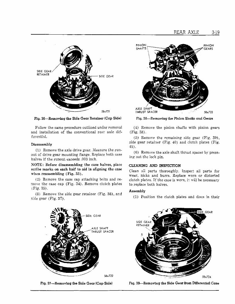
Fig. 36—Removing the Side Gear Retainer (Cap Side)
Follow the same procedure outlined under removal and installation of the conventional rear axle differential
Disassembly
(1) Remove the axle drive gear. Measure the runout of drive gear mounting flange. Replace both case halves if the runout exceeds .003 inch. NOTE: Before disassembling the case halves, place scribe marks on each half to aid in aligning the case when reassembling (Fig. 33).
(2) Remove the case cap attaching bolts and remove the'case cap (Fig. 34). Remove clutch plates (Fis.35).
(8) Remove the side gear retainer (Fig. 38), and side gear (Fig. 37).
Fig. 37—Removing the Side Gear (Cap Side)
T H R U S T S P A C E R
Fig. 38—Removing the Pinion Shafts and Gears
(4) Remove the pinion shafts with pinion gears (Fig. 38).
(5) Remove the remaining side gear (Fig. 39), side gear retainer (Fig. 40) and clutch plates (Fig. 41).
(6) Remove the axle shaft thrust spacer by pressing out the lock pin.
CLEANING AND INSPECTION Clean all parts thoroughly. Inspect all parts for wear, nicks and burrs. Replace worn or distorted clutch plates. I f the case is worn, i t will be necessary to replace both halves.
Assembly (1) Position the clutch plates and discs in their
Fig. 39—Removing the Side Gear from Differential Case

3-20 REAR AXLE
Fig. 40—Removing the Side Gear Retainer
proper position in each half of the ease, as shown in Figure 42,
(2) Place the side gears in their retainers. Insert splines of the retainers through the splines of the clutch discs.
(3) Place the aligning pin through one axle shaft thrust spacer. Assemble the pinion shafts on the aligning pin.
(4) Place the pinion gears on the shafts and install the assembly on the drive gear half of the case. Insert the thrust spacer In the pinion shaft (Fig. 43).
(5) Slide the cap half of the case over the edge of the bench far enough to Insert one finger up through the assembly to hold It together. Place the assembly on drive gear half, matching the scribe marks.
(6) Make sure the markings on each differential
Fig. 41—-Removing the Clutch Plates
Fig. 42—Arrangement oitQutch Plates; Discs and Washers
58x727
Fig. 43—Installing Axle Shaft Thrust Spacers
FEELER G A U G E S
Fig. 44—Measuring Clearance Between Pinion Shafts and Case

REAR AXLE 3-21
case half coincide. Install the differential case bolts and turn them in a few threads.
(7) Install the axle shafts from the vehicle to align the splines. Make sure the axle shafts engage the side gear splines as well as the clutch ring splines.
(8) With the shafts installed, center the cross shafts between the two ramp surfaces in the differential case. Tighten the differential case bolts evenly by alternately turning opposite bolts until all are torque tightened to 45 foot-pounds. After assembly, slight misalignments of the splines can be corrected by moving the axle shafts back and forth until free. Remove the axle- shafts.
• (9) With the differential resting on one hub, insert-two feeler blades, one over each end of the pinion' shaft having ramps above it (Fig. 44). The clearance should not exceed .010 inch at each end of shaft.
(10) Invert the differential to rest on the opposite hub. Measure the opposite pinion shaft in the like manner to the same specifications (Fig. 45).
Measurements over .010 inch indicate that the clutch discs are worn and should be replaced. New
FEELER G A U G E S
Fig. 45—Measuring Clearance of Pinion Shaft and Cap
discs and plates may produce a clearance of as little as .002 inch. With either new or used discs, the measurement of the two shafts should be within .005 of each other.
Use Tool C-3565 driver when installing the rear axle shaft outer oil seal and Tool C-745 seal protector when installing the brake shield over the rear axle shaft.
SERVICE DIAGNOSIS
Condi t ions Possible C a u s e Cor rect ions
(a) Wheel loose on axle shaft. (a) Tighten wheel in sequence outlined in "Wheels and Tires".
(b) Worn drum or worn axle shaft (b) Replace drum or axle shaft as necessary. keyways.
(c) Wheel hub bolts loose. fc) Tighten bolts to correct torque. (d) Brinnelled or scored wheel bearings. (d) Replace wheel bearings. (e) Insufficient lubrication. (e) Add lubricant as required. (f) Improper axle shaft end play. (f) Adjust end play to .013-.018 inch. (g) Bent axle shaft or wheel and hub. (g) Replace wheel, hub or drum as necessary.
(a) Lubricant level low. (a) Add lubricant as required. (b) E n d play in drive pinion bearing. (b) Measure and adjust end play. (c) Excessive gear lash between ring (c) Measure and adjust gear lash.
gear and pinion. (d) Loose drive pinion companion (d) Tighten flange nut to 240 (min.) foot
flange nut. pounds. (e) Damaged gears. (e) Replace gears as required.
R e a r Wheel Noise
Rear Axle Noise

3-22 REAR AXLE
SERVICE DIAGNOSIS—CONT'D.
Conditions Possible Cause Corrections
Over-Heating of the (a) Lubricant level too low. (a) Add lubricant as required. Axle Unit
(b) Bearing adjusted too tightly. (b) Adjust bearings correctly. (c) Excessive wear in gears. (c) Replace excessively worn gears.
Loss of Lubricant (a) Lubricant level too high. (a) Remove excessive lubricant. (b) Improper type lubricant. (b) Remove lubricant and replace with the
recommended type. (c) Clogged breather. (c) Clean breather thoroughly. (d) Oil seals worn. (d) Replace seals as required.