Embed Size (px)
Citation preview
REALTIME DIGITAL SIGNAL PROCESSING IN COHERENT OPTICAL PDM-QPSK AND PDM-16-QAM TRANSMISSION
R. Noé*, M. F. Panhwar*, C. Wördehoff** and D. Sandel* *EIM-E, Univ. Paderborn, Warburger Str. 100, D-33098 Paderborn, Germany
**CITEC, Univ. Bielefeld, Universitätsstr. 21-23, D-33615 Bielefeld, Germany
Email: [email protected] (Invited Paper)
Abstract Coherent fiberoptic transmission with synchronous detection of 4, 8 or more bit/symbol enhances spectral efficiency. It relies on polarization-division multiplexing (PDM) and quadrature phase shift keying (QPSK) or higher-order quadrature amplitude modulation (QAM). A coherent polarization diversity, in-phase and quadrature receiver detects the optical field information. Its most important tasks are to recover the carrier in a laser phase noise tolerant manner and to control optical polarization electronically. We present suitable digital signal processing designs and their usage in realtime coherent transmission. We likewise discuss chromatic dispersion (CD) and polarization mode dispersion (PMD) equalization, needed for longer fibers.
Index Terms— Digital signal processing, coherent fiberoptic transmission, polarization-division multiplexing, polarization control, equalization
1. INTRODUCTION Digital signal processing (DSP) based coherent fiberoptic transmission allows for improved bandwidth utilization and impairment compensation of existing optical fiber links. In this respect, QPSK or higher-order QAM are used in cohe-rent PDM systems to enhance the overall spectral efficiency [1-5]. However, fast polarization state and polarization-dependent loss (PDL) changes occuring in the fiber channel could severely deteriorate the receiver sensitivity. Hence we have investigated and implemented an endless digital pola-rization control to track fast polarization changes [6-8]. Furthermore, a linewidth tolerant feedforward carrier recov-ery that avoids feedback loops is needed for higher-order QAM constellations. So, we have proposed and imple-mented a hardware-efficient feedforward carrier recovery concept for synchronous decoding of arbitrary M-QAM [5,9-11]. It enables the usage of low-cost distributed feed-back (DFB) lasers even high-order QAM. Moreover, CD and PMD equalization is also necessary for increasing fibe-roptic transmission distances [12-14]. In practice, complex signal processing chips are needed [1, 2, 15]. Support from the Deutsche Forschungsgemeinschaft (DFG) is gratefully acknowlegded.
2. PRINCIPLE AND DESIGN CONTRAINTS OF REALTIME DIGITAL COHERENT RECEIVERS
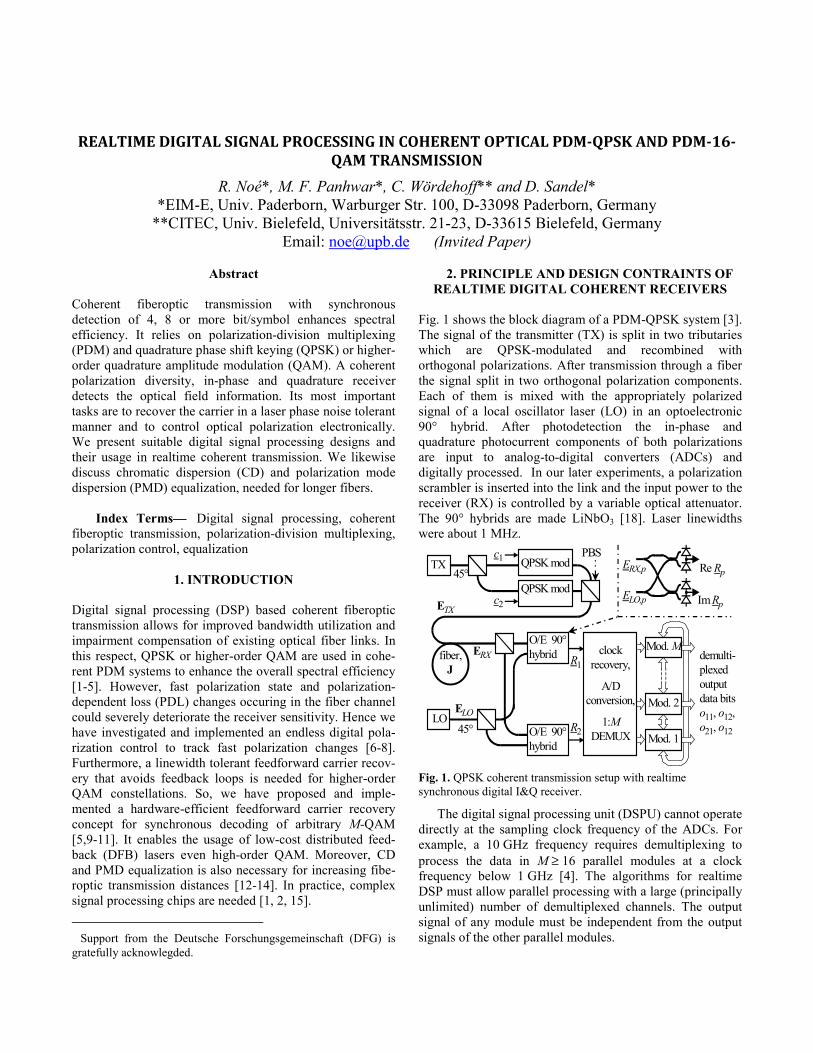
Fig. 1 shows the block diagram of a PDM-QPSK system [3]. The signal of the transmitter (TX) is split in two tributaries which are QPSK-modulated and recombined with orthogonal polarizations. After transmission through a fiber the signal split in two orthogonal polarization components. Each of them is mixed with the appropriately polarized signal of a local oscillator laser (LO) in an optoelectronic 90° hybrid. After photodetection the in-phase and quadrature photocurrent components of both polarizations are input to analog-to-digital converters (ADCs) and digitally processed. In our later experiments, a polarization scrambler is inserted into the link and the input power to the receiver (RX) is controlled by a variable optical attenuator. The 90° hybrids are made LiNbO3 [18]. Laser linewidths were about 1 MHz.
demulti-plexed output data bits o11, o12, o21, o12
Mod. 1
Mod. 2
Mod. MERX
ELOLO
fiber,J
45°
O/E 90° hybrid clock
recovery,
A/D conversion,
1:M DEMUX
ETX
R1
R2
TX45°
QPSK mod
QPSK mod
c1
c2
O/E 90° hybrid
ERX,p
ELO,p ImRp
Re Rp
PBS
Fig. 1. QPSK coherent transmission setup with realtime synchronous digital I&Q receiver.
The digital signal processing unit (DSPU) cannot operate directly at the sampling clock frequency of the ADCs. For example, a 10 GHz frequency requires demultiplexing to process the data in M ≥ 16 parallel modules at a clock frequency below 1 GHz [4]. The algorithms for realtime DSP must allow parallel processing with a large (principally unlimited) number of demultiplexed channels. The output signal of any module must be independent from the output signals of the other parallel modules.
An important consideration for realtime DSP algorithms is the tolerable feedback delay. Due to the parallel processing and massive pipelining which are necessary to cope with the required high data-rates it can easily take >100 symbol durations (~10 ns @ 10 Gbaud) until a received symbol has an impact on the feedback signal. For polarization control or CD and PMD equalization, several nanoseconds of additional delay can be neglected. However, algorithms that require an instantaneous feedback, in particular decision-directed carrier recovery and infinite impulse response filters, usually can not be implemented. Hence, feedforward carrier recovery and finite impulse response (FIR) filters become mandatory.
Another constraint for the implementation of realtime coherent receiver algorithms is hardware efficiency. Computationally intensive algorithms require a huge amount of chip area and therefore an increased power consumption and cost. Hardware efficiency can be achieved by signal domain or coordinate transformations and log-function. In particular, an FFT/IFFT based implementation reduces a convolution operation to multiplications, and polar coordinates and the log-function replace multiplications by summations.
The usual sequence of processing steps is CD compensation by one scalar equalizer for each polarization, PMD compensation (including final polarization rotations), carrier and data recovery.
3. FEEDFORWARD CARRIER RECOVERY
In the absence of laser phase noise, received subsequent QPSK symbols have equal amplitude and phases which differ by integer multiples of π/2. A simple way of carrier recovery is to raise the received signal to the 4th power. This quadruples the phase angle. To improve signal quality, a couple of, say, 9 adjacent 4th-power phasors are averaged. The phase of the average phasor is determined and divided by 4 to recover the carrier phase. In the presence of laser phase noise the recovered carrier phase drifts. In other phasor quadrants, i.e. outside a π/2 wide range of the recovered phase, it must be unwrapped. Differential quadrant number encoding is a simpler alternative approach [3].
Instead of working with a 4th-power phasor it is possible to determine the phase of each symbol. Phases of each symbol are then averaged modulo π/2. Using this method, we have implemented a realtime coherent QPSK system [7, 8], starting at 200 Mbaud, later up to 700 Mbaud and enhanced with PDM [6]. The DSPU consisted of an FPGA. Results will be given in the next Section.
4. DIGITAL POLARIZATION CONTROL
In coherent receivers employing PDM the ability to accommodate the ever-changing polarization states is essential. The two received complex signals R1, R2 (Fig. 1)
are proportional to optical fields and can be considered as the electrical replica of a Jones vector R = [R1, R2]T (T = transpose). It is results from the vector c of transmitted symbols by a multiplication with the unknown fiber Jones matrix J and a phasor whose phase Δϕ is that between signal and LO lasers, R = JcejΔϕ. The carrier recovery takes care of Δϕ. However, R must be multplied by a compensation matrix H which is proportional to the inverse of J. This was also implemented. The elements of H were adapted to follow the changes of J.
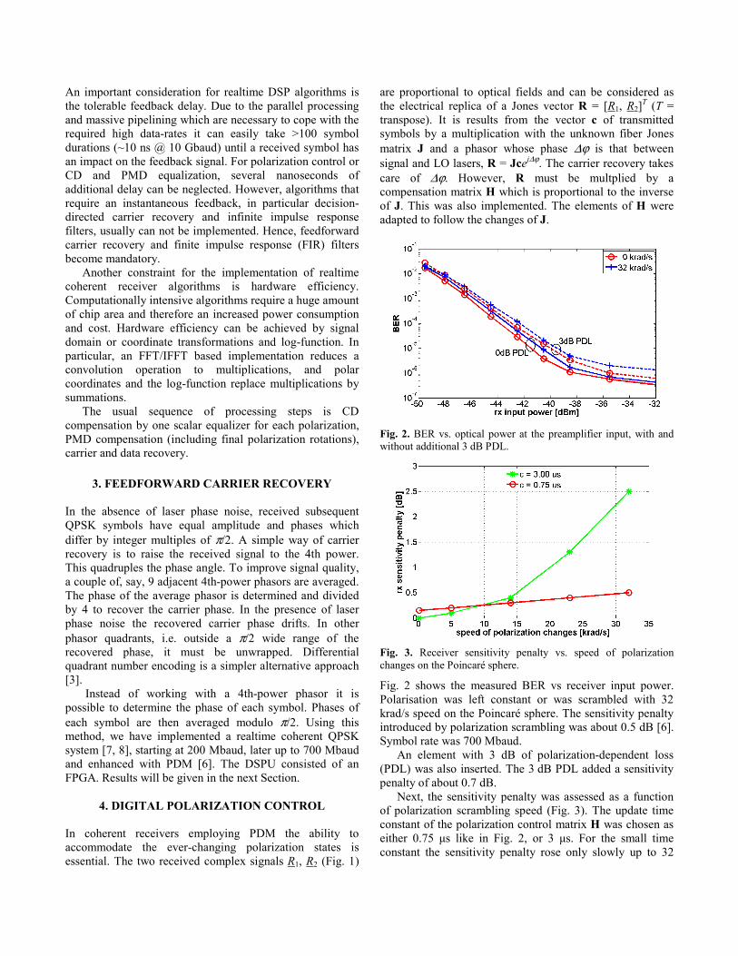
Fig. 2. BER vs. optical power at the preamplifier input, with and without additional 3 dB PDL.
Fig. 3. Receiver sensitivity penalty vs. speed of polarization changes on the Poincaré sphere.
Fig. 2 shows the measured BER vs receiver input power. Polarisation was left constant or was scrambled with 32 krad/s speed on the Poincaré sphere. The sensitivity penalty introduced by polarization scrambling was about 0.5 dB [6]. Symbol rate was 700 Mbaud.
An element with 3 dB of polarization-dependent loss (PDL) was also inserted. The 3 dB PDL added a sensitivity penalty of about 0.7 dB.
Next, the sensitivity penalty was assessed as a function of polarization scrambling speed (Fig. 3). The update time constant of the polarization control matrix H was chosen as either 0.75 μs like in Fig. 2, or 3 μs. For the small time constant the sensitivity penalty rose only slowly up to 32
krad/s scrambling speed. For the large time constant, the same penalty was reached already at 15 krad/s, but sensitivity was about 0.2 dB better at low or vanishing scrambling speed.
5. PDM-QPSK RECEIVER WITH ASICS
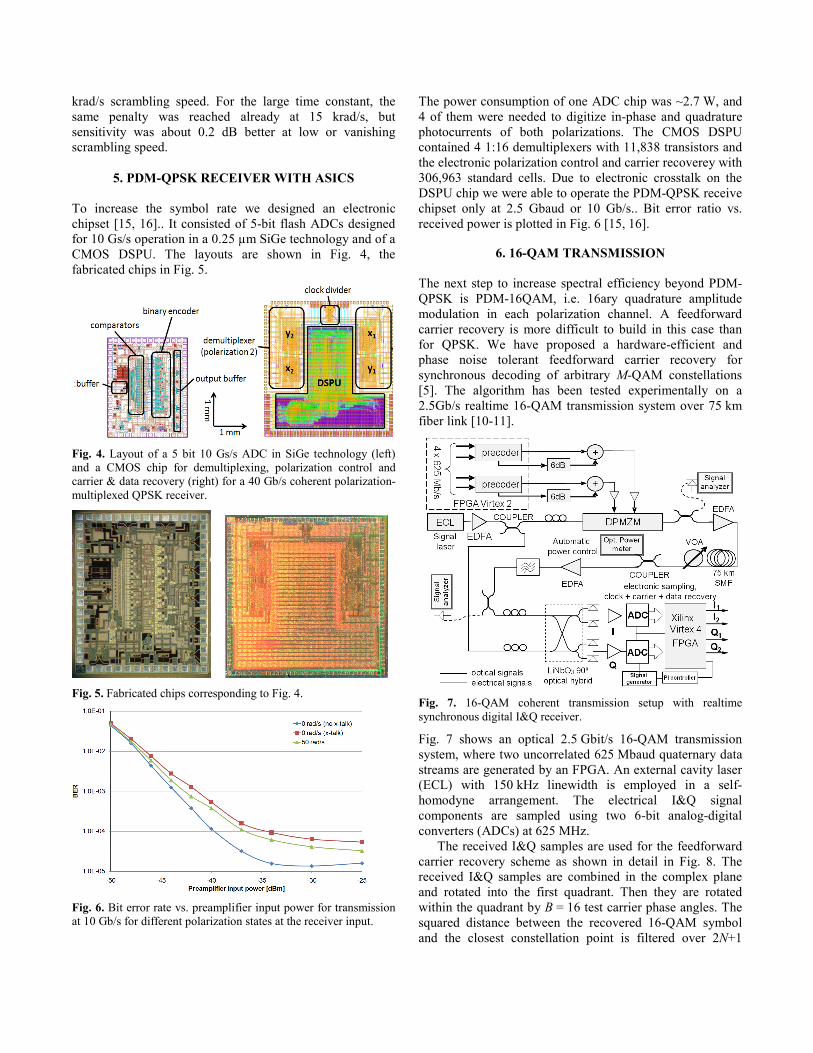
To increase the symbol rate we designed an electronic chipset [15, 16].. It consisted of 5-bit flash ADCs designed for 10 Gs/s operation in a 0.25 µm SiGe technology and of a CMOS DSPU. The layouts are shown in Fig. 4, the fabricated chips in Fig. 5.
Fig. 4. Layout of a 5 bit 10 Gs/s ADC in SiGe technology (left) and a CMOS chip for demultiplexing, polarization control and carrier & data recovery (right) for a 40 Gb/s coherent polarization-multiplexed QPSK receiver.
Fig. 5. Fabricated chips corresponding to Fig. 4.
Fig. 6. Bit error rate vs. preamplifier input power for transmission at 10 Gb/s for different polarization states at the receiver input.
The power consumption of one ADC chip was ~2.7 W, and 4 of them were needed to digitize in-phase and quadrature photocurrents of both polarizations. The CMOS DSPU contained 4 1:16 demultiplexers with 11,838 transistors and the electronic polarization control and carrier recoverey with 306,963 standard cells. Due to electronic crosstalk on the DSPU chip we were able to operate the PDM-QPSK receive chipset only at 2.5 Gbaud or 10 Gb/s.. Bit error ratio vs. received power is plotted in Fig. 6 [15, 16].
6. 16-QAM TRANSMISSION
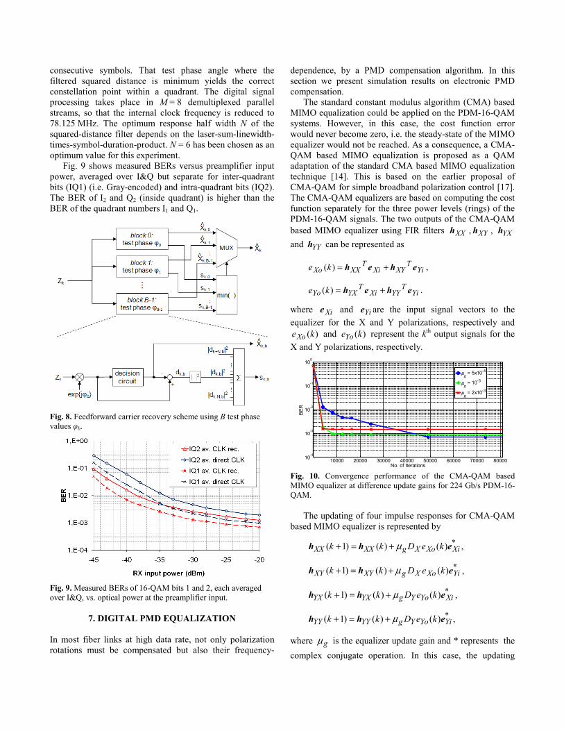
The next step to increase spectral efficiency beyond PDM-QPSK is PDM-16QAM, i.e. 16ary quadrature amplitude modulation in each polarization channel. A feedforward carrier recovery is more difficult to build in this case than for QPSK. We have proposed a hardware-efficient and phase noise tolerant feedforward carrier recovery for synchronous decoding of arbitrary M-QAM constellations [5]. The algorithm has been tested experimentally on a 2.5Gb/s realtime 16-QAM transmission system over 75 km fiber link [10-11].
Fig. 7. 16-QAM coherent transmission setup with realtime synchronous digital I&Q receiver.
Fig. 7 shows an optical 2.5 Gbit/s 16-QAM transmission system, where two uncorrelated 625 Mbaud quaternary data streams are generated by an FPGA. An external cavity laser (ECL) with 150 kHz linewidth is employed in a self-homodyne arrangement. The electrical I&Q signal components are sampled using two 6-bit analog-digital converters (ADCs) at 625 MHz.
The received I&Q samples are used for the feedforward carrier recovery scheme as shown in detail in Fig. 8. The received I&Q samples are combined in the complex plane and rotated into the first quadrant. Then they are rotated within the quadrant by B = 16 test carrier phase angles. The squared distance between the recovered 16-QAM symbol and the closest constellation point is filtered over 2N+1
consecutive symbols. That test phase angle where the filtered squared distance is minimum yields the correct constellation point within a quadrant. The digital signal processing takes place in M = 8 demultiplexed parallel streams, so that the internal clock frequency is reduced to 78.125 MHz. The optimum response half width N of the squared-distance filter depends on the laser-sum-linewidth-times-symbol-duration-product. N = 6 has been chosen as an optimum value for this experiment.
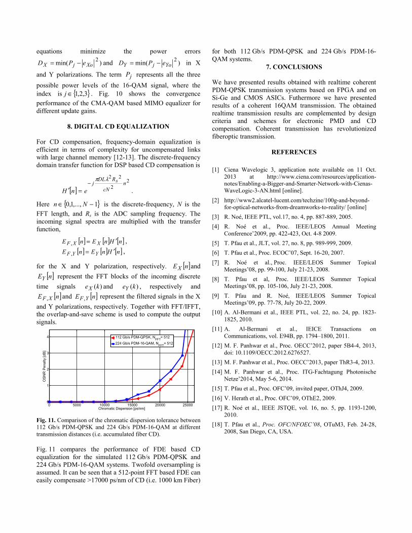
Fig. 9 shows measured BERs versus preamplifier input power, averaged over I&Q but separate for inter-quadrant bits (IQ1) (i.e. Gray-encoded) and intra-quadrant bits (IQ2). The BER of I2 and Q2 (inside quadrant) is higher than the BER of the quadrant numbers I1 and Q1.
Fig. 8. Feedforward carrier recovery scheme using B test phase values φb.
Fig. 9. Measured BERs of 16-QAM bits 1 and 2, each averaged over I&Q, vs. optical power at the preamplifier input.
7. DIGITAL PMD EQUALIZATION
In most fiber links at high data rate, not only polarization rotations must be compensated but also their frequency-
dependence, by a PMD compensation algorithm. In this section we present simulation results on electronic PMD compensation.
The standard constant modulus algorithm (CMA) based MIMO equalization could be applied on the PDM-16-QAM systems. However, in this case, the cost function error would never become zero, i.e. the steady-state of the MIMO equalizer would not be reached. As a consequence, a CMA-QAM based MIMO equalization is proposed as a QAM adaptation of the standard CMA based MIMO equalization technique [14]. This is based on the earlier proposal of CMA-QAM for simple broadband polarization control [17]. The CMA-QAM equalizers are based on computing the cost function separately for the three power levels (rings) of the PDM-16-QAM signals. The two outputs of the CMA-QAM based MIMO equalizer using FIR filters XXh , XYh , YXh and YYh can be represented as
YiT
XYXiT
XXXo ke eheh +=)( ,
YiT
YYXiT
YXYo ke eheh +=)( .
where Xie and Yie are the input signal vectors to the equalizer for the X and Y polarizations, respectively and
)(keXo and )(keYo represent the kth output signals for the X and Y polarizations, respectively.
10000 20000 30000 40000 50000 60000 70000 8000010-4
10-3
10-2
10-1
100
No. of Iterations
BE
R
μg = 5x10⁻⁴
μg = 10-3
μg = 2x10⁻³
Fig. 10. Convergence performance of the CMA-QAM based MIMO equalizer at difference update gains for 224 Gb/s PDM-16-QAM.
The updating of four impulse responses for CMA-QAM based MIMO equalizer is represented by
*XiXoXgXXXX keDkk ehh )()()1( μ+=+ ,
*YiXoXgXYXY keDkk ehh )()()1( μ+=+ ,
*XiYoYgYXYX keDkk ehh )()()1( μ+=+ ,
*YiYoYgYYYY keDkk ehh )()()1( μ+=+ ,
where gμ is the equalizer update gain and * represents the complex conjugate operation. In this case, the updating
equations minimize the power errors
)min( 2XojX ePD −= and )min( 2
YojY ePD −= in X
and Y polarizations. The term jP represents all the three possible power levels of the 16-QAM signal, where the index is { }3,2,1∈j . Fig. 10 shows the convergence performance of the CMA-QAM based MIMO equalizer for different update gains.
8. DIGITAL CD EQUALIZATION For CD compensation, frequency-domain equalization is efficient in terms of complexity for uncompensated links with large channel memory [12-13]. The discrete-frequency domain transfer function for DSP based CD compensation is
[ ]2
2
22n
cN
RDLj s
enH
λπ−
=′ .
Here { }1,...,1,0 −∈ Nn is the discrete-frequency, N is the FFT length, and Rs is the ADC sampling frequency. The incoming signal spectra are multiplied with the transfer function,
[ ] [ ] [ ]nHnEnE XXF ′=, , [ ] [ ] [ ]nHnEnE YYF ′=, ,
for the X and Y polarization, respectively. [ ]nEX and [ ]nEY represent the FFT blocks of the incoming discrete
time signals )(keX and )(keY , respectively and [ ]nE XF , and [ ]nE YF , represent the filtered signals in the X
and Y polarizations, respectively. Together with FFT/IFFT, the overlap-and-save scheme is used to compute the output signals.
0 5000 10000 15000 20000 250000
1
2
3
4
Chromatic Dispersion [ps/nm]
OS
NR
Pen
alty
[dB
]
112 Gb/s PDM-QPSK, NFFT
= 512
224 Gb/s PDM-16-QAM, NFFT= 512
Fig. 11. Comparison of the chromatic dispersion tolerance between 112 Gb/s PDM-QPSK and 224 Gb/s PDM-16-QAM at different transmission distances (i.e. accumulated fiber CD).
Fig. 11 compares the performance of FDE based CD equalization for the simulated 112 Gb/s PDM-QPSK and 224 Gb/s PDM-16-QAM systems. Twofold oversampling is assumed. It can be seen that a 512-point FFT based FDE can easily compensate >17000 ps/nm of CD (i.e. 1000 km Fiber)
for both 112 Gb/s PDM-QPSK and 224 Gb/s PDM-16-QAM systems.
7. CONCLUSIONS
We have presented results obtained with realtime coherent PDM-QPSK transmission systems based on FPGA and on Si-Ge and CMOS ASICs. Futhermore we have presented results of a coherent 16QAM transmission. The obtained realtime transmission results are complemented by design criteria and schemes for electronic PMD and CD compensation. Coherent transmission has revolutionized fiberoptic transmission.
REFERENCES [1] Ciena Wavelogic 3, application note available on 11 Oct.
2013 at http://www.ciena.com/resources/application-notes/Enabling-a-Bigger-and-Smarter-Network-with-Cienas-WaveLogic-3-AN.html [online].
[2] http://www2.alcatel-lucent.com/techzine/100g-and-beyond-for-optical-networks-from-dreamworks-to-reality/ [online]
[3] R. Noé, IEEE PTL, vol.17, no. 4, pp. 887-889, 2005. [4] R. Noé et al., Proc. IEEE/LEOS Annual Meeting
Conference’2009, pp. 422-423, Oct. 4-8 2009. [5] T. Pfau et al., JLT, vol. 27, no. 8, pp. 989-999, 2009. [6] T. Pfau et al., Proc. ECOC’07, Sept. 16-20, 2007. [7] R. Noé et al., Proc. IEEE/LEOS Summer Topical
Meetings’08, pp. 99-100, July 21-23, 2008. [8] T. Pfau et al, Proc. IEEE/LEOS Summer Topical
Meetings’08, pp. 105-106, July 21-23, 2008. [9] T. Pfau and R. Noé, IEEE/LEOS Summer Topical
Meetings’09, pp. 77-78, July 20-22, 2009. [10] A. Al-Bermani et al., IEEE PTL, vol. 22, no. 24, pp. 1823-
1825, 2010. [11] A. Al-Bermani et al., IEICE Transactions on
Communications, vol. E94B, pp. 1794–1800, 2011. [12] M. F. Panhwar et al., Proc. OECC’2012, paper 5B4-4, 2013,
doi: 10.1109/OECC.2012.6276527. [13] M. F. Panhwar et al., Proc. OECC’2013, paper ThR3-4, 2013. [14] M. F. Panhwar et al., Proc. ITG-Fachtagung Photonische
Netze’2014, May 5-6, 2014. [15] T. Pfau et al., Proc. OFC’09, invited paper, OThJ4, 2009. [16] V. Herath et al., Proc. OFC’09, OThE2, 2009. [17] R. Noé et al., IEEE JSTQE, vol. 16, no. 5, pp. 1193-1200,
2010. [18] T. Pfau et al., Proc. OFC/NFOEC’08, OTuM3, Feb. 24-28,
2008, San Diego, CA, USA.