Embed Size (px)
Citation preview

Reality Engineering IIJeremy D. RuckSenior EngineerD.L. Markley & Associates, Inc.2104 West Moss AvenuePeoria, IL 61604(309) [email protected]


Reality EngineeringJeremy D. RuckSenior EngineerD.L. Markley & Associates, Inc.2104 West Moss AvenuePeoria, IL 61604(309) [email protected]
II

Reality Engineering II
• Definitions.• Flange Reflection Pile-Up.• Maintain and Check Your Line.• Regulatory Stuff.• Some Stuff about Coverage.

Definitions of Reality
• The state or quality of being real.• Resemblance to what is real.• The state of the world as it actually is
rather than as you might want it to be.

Definitions of Engineering
• The practical application of science to commerce or industry.
• The discipline dealing with the art or science of applying scientific knowledge to practical problems.
• Skillfully or shrewdly managing an enterprise.

Flange Reflection Pile-Up

Flange Reflection Pile-Up
• We all understand that only certain section lengths of line function on particular channels.
• Why do appropriate section lengths matter and how is flange reflection pile-up manifested?
• Why is this a problem and what solutions are there to mitigate the issue?

Section Lengths

Section Lengths
• Proper section lengths are a function of frequency.
• Flange reflection pile-up results from minor discontinuities at flanges.
• Discontinuity is a function of differential temperature. Compensation can onlyoccur at one differential.
• Avoid having a section length that is a half-wavelength multiple within your frequency range of operation.

Section Lengths
• VSWR resulting from flange reflection pile-up is a function of temperature and is sharply frequency sensitive.
• Avoid being within 2 MHz to critical frequencies.
• Critical frequencies for 20, 19.75, and 19.5 sections are multiples of 24.52 MHz, 24.83 MHz, and 25.15 MHz respectively.

Section Lengths
• Critical frequencies are approximately determined from the following equation:
• In this equation f is the frequency in MHz, n is any integer, and L is the section length in feet.• It follows then that we can rearrange terms and solve for the quantity in which we are interested.
Lnf 4.490
=

Section Lengths
• If we wanted 10 foot sections, then we would have critical frequencies every 49.04 MHz.
• Assuming this is our section length and avoiding being within 2 MHz of a resonance, we find channels 10, 16, 17, 25, 33, 34, 41, 42, 49, and 50 would be excluded.

Section Lengths
• The number 490.4 comes out of the English unit calculation for wavelength.
• Remember that a wavelength is the quotient of the velocity of light and frequency in free space.
• The converse of this is the velocity of light is equivalent to the product of wavelength and frequency in free space.

Flange Reflection Manifestation and Mitigation
• Two years ago in “Trade Secrets of a Guy with a Network Analyzer” we discussed the use of wide band time domain data to consider the “integrity”of the line.
• We will process that set of data further to illustrate how the flange reflection pile-up manifests itself in a run of transmission line.

Flange Reflection Manifestation and Mitigation
CH1 MEM SWR 20 m / REF 1
START-5 ns STOP 3.2 us
*
Cor
Hld
MARKER 1 2.5831 us
774.4 m
9 Oct 2007 15:46:03
1
2
3
1 : 1 . 0260 2.583 us
CH1 Markers
2 : 1 . 0160114 . 87 ns
3 : 1 . 0351-839 ps

Flange Reflection Manifestation and Mitigation
CH1 MEM SWR 20 m / REF 1
START-5 ns STOP 3.2 us
*
Cor
Hld
GATE CENTER 1.3088 us
392.37 m
9 Oct 2007 15:46:49

Flange Reflection Manifestation and Mitigation
CH1 MEM SWR 20 m / REF 1
START-5 ns STOP 3.2 us
*
GatCor
Hld
GATE CENTER 1.3088 us
392.37 m
9 Oct 2007 15:47:08

Flange Reflection Manifestation and Mitigation
CH1 MEM SWR 100 m / REF 1
START 585 . 000 000 MHz STOP 685 . 000 000 MHz
*
GatCor
Hld
MARKER 2 635 MHz
9 Oct 2007 15:50:11
1
2
3
2 : 1 . 0125 635 . 000 000 MHz
CH1 Markers
1 : 1 . 0098632 . 000 MHz
3 : 1 . 0217638 . 000 MHz

Flange Reflection Manifestation and Mitigation
CH1 MEM SWR 100 m / REF 1
START 585 . 000 000 MHz STOP 685 . 000 000 MHz
*
GatCor
Hld
MARKER 2 629 MHz
9 Oct 2007 15:50:54
1
2
3
2 : 1 . 0950 629 . 000 000 MHz
CH1 Markers
1 : 1 . 0405626 . 000 MHz
3 : 1 . 0098632 . 000 MHz

Flange Reflection Manifestation and Mitigation
CH1 MEM SWR 200 m / REF 1
START 585 . 000 000 MHz STOP 685 . 000 000 MHz
*
GatCor
Hld
MARKER 1 603.125 MHz
9 Oct 2007 16:12:26
1
23
4
1 : 2 . 5684 603 . 125 000 MHz
CH1 Markers
2 : 1 . 7453628 . 260 MHz
3 : 1 . 7039653 . 390 MHz
4 : 2 . 4470678 . 520 MHz

Flange Reflection Manifestation and Mitigation
CH1 MEM SWR 200 m / REF 1
START 585 . 000 000 MHz STOP 685 . 000 000 MHz
*
GatCor
Hld
MARKER 3-2 25.13 MHz
9 Oct 2007 16:12:39
1
2
3
4
3 : -41 . 418 m 25 . 130 000 MHz
REF=2CH1 Markers
1 : 823 . 02 m-25 . 1350 MHz
2 : 0 . 00000 . 00000 Hz
4 : 701 . 70 m50 . 2600 MHz
Flange Reflection Manifestation and Mitigation
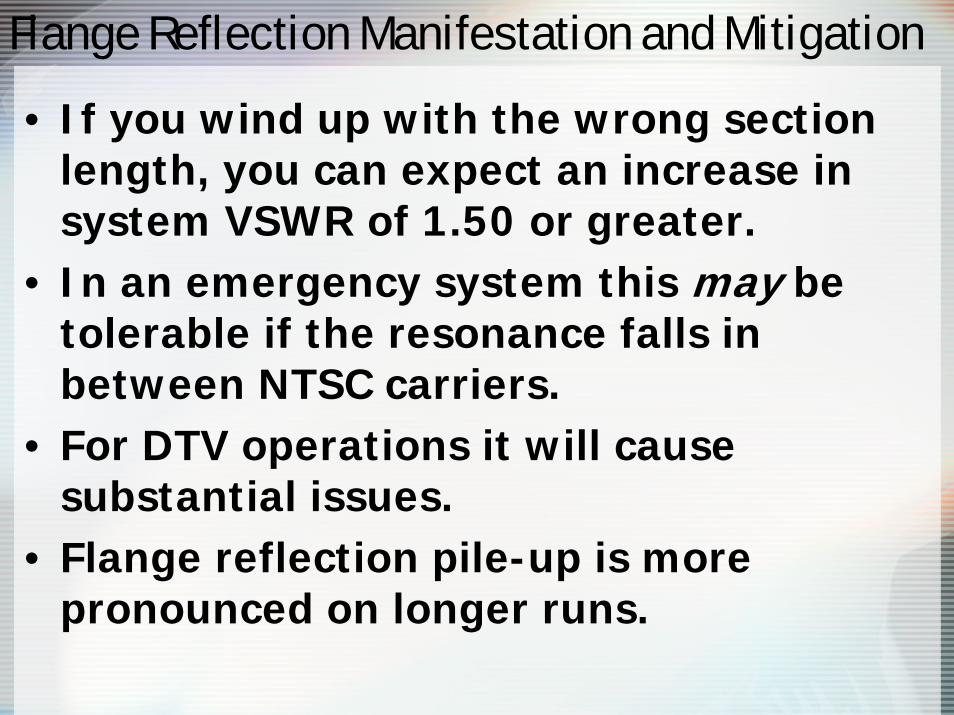
• If you wind up with the wrong section length, you can expect an increase in system VSWR of 1.50 or greater.
• In an emergency system this may be tolerable if the resonance falls in between NTSC carriers.
• For DTV operations it will cause substantial issues.
• Flange reflection pile-up is more pronounced on longer runs.

Reducing Reflection Pile-Up
Reducing Flange Reflection Pile-Up
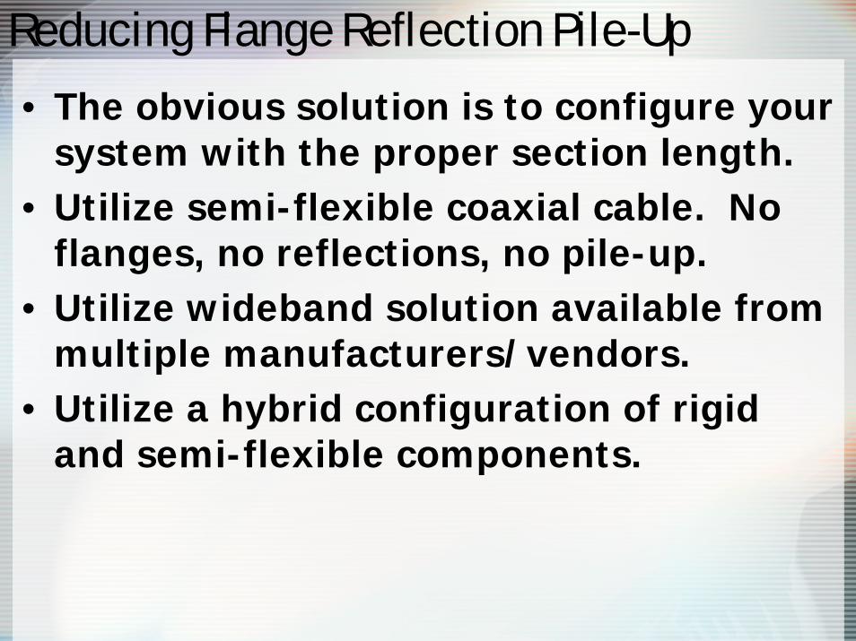
• The obvious solution is to configure your system with the proper section length.
• Utilize semi-flexible coaxial cable. No flanges, no reflections, no pile-up.
• Utilize wideband solution available from multiple manufacturers/vendors.
• Utilize a hybrid configuration of rigid and semi-flexible components.

Reducing Flange Reflection Pile-Up
CH1 MEM SWR 10 m / REF 1
START-5 ns STOP 2.5 us
*
KQDS-DT
Cor
Avg0
Hld
MARKER 1 1.5862 us
475.52 m
9 Oct 2007 17:07:29
1
2
3
4
5
1 : 1 . 0125 1.586 us
CH1 Markers
2 : 1 . 0052270 . 55 ns
3 : 1 . 0162210 . 93 ns
4 : 1 . 009183 . 428 ns
5 : 1 . 0566
0 s

Reducing Flange Reflection Pile-Up
CH1 MEM SWR 10 m / REF 1
START-5 ns STOP 2.5 us
*
KQDS-DT
GatCor
Avg0
Hld
GATE CENTER 920 ns
275.81 m
9 Oct 2007 17:08:29
1
2345
1 : 1 . 0000 1.586 us
CH1 Markers
2 : 1 . 0001270 . 55 ns
3 : 1 . 0000210 . 93 ns
4 : 1 . 000083 . 428 ns
5 : 1 . 0000
0 s

Reducing Flange Reflection Pile-Up
CH1 MEM SWR 10 m / REF 1
CENTER 491 . 000 000 MHz SPAN 100 . 000 000 MHz
*
KQDS-DT
GatCor
Avg0
Hld
MARKER 2 491 MHz
9 Oct 2007 17:10:39
1
2
3
4
5
2 : 1 . 0092 491 . 000 000 MHz
CH1 Markers
1 : 1 . 0042488 . 000 MHz
3 : 1 . 0059494 . 000 MHz
4 : 1 . 0583452 . 590 MHz
5 : 1 . 0527
502 . 960 MHz

Maintain and Check Your Line

Maintain and Check Your Line
• We have talked about this before, but remember transmission line is not something to ignore.
• Have your system swept every few years to discern impending problems.
• Retrofit transmission line at proper intervals. Usually about 15 years is a good time span.
• Rectify discovered issues promptly.

Maintain and Check Your Line
CH1 MEM SWR 50 m / REF 1
START 174 . 000 000 MHz STOP 180 . 000 000 MHz
WPBN-NTSC
Cor
Avg16
MARKER 1 175.26 MHz
24 Sep 2007 16:55:49
1
23
4
5
1 : 1 . 0934 175 . 260 000 MHz
CH1 Markers
2 : 1 . 0637179 . 760 MHz
3 : 1 . 0637178 . 839 MHz
4 : 1 . 1844178 . 485 MHz
5 : 1 . 0018
175 . 867 MHz

Maintain and Check Your Line
CH1 MEM SWR 10 m / REF 1
START-5 ns STOP 3 us
WPBN-NTSC
Cor
Avg13
MARKER 1 2.115 us
634.07 m
24 Sep 2007 16:57:18
1
2
3
45
1 : 1 . 0443 2.115 us
CH1 Markers
2 : 1 . 02411 . 783 us
3 : 1 . 01991 . 082 us
4 : 1 . 0295522 . 08 ns
5 : 1 . 0288
0 s

Maintain and Check Your Line
CH1 MEM SWR 20 m / REF 1
START-5 ns STOP 3 us
WPBN-NTSC
Cor
Avg16
MARKER 1 2.3909 us
716.77 m
24 Sep 2007 17:01:01
1
2
3
4
5
1 : 1 . 0032 2.390 us
CH1 Markers
2 : 1 . 07562 . 144 us
3 : 1 . 04071 . 173 us
4 : 1 . 0263439 . 44 ns
5 : 1 . 0611
25 . 053 ns

Maintain and Check Your Line
CH1 MEM SWR 15 m / REF 1
START-5 ns STOP 2.5 us
WPBN-NTSC
Cor
Avg16
MARKER 1 2.0319 us
609.14 m
24 Sep 2007 17:02:40
1
2
3
4
5
1 : 1 . 0594 2.031 us
CH1 Markers
2 : 1 . 08041 . 870 us
3 : 1 . 06051 . 257 us
4 : 1 . 1919645 . 31 ns
5 : 1 . 0700
440 . 9 ns

Maintain and Check Your Line
• Station had recent localized failure of transmission line.
• Minimal repair was employed to return the station to air.
• Further testing of line indicated a large number of substantial issues with the transmission line.
• Future failures likely without retrofit being performed.

Maintain and Check Your Line
• Transmission line is about 45 years old and of a type no longer supported.
• Consideration was made to investigate larger reflections, but without replacement parts on hand this plan was scrubbed.
• This is probably the best course of action in similar instances.
• Entire run will likely need to be replaced.

Maintain and Check Your Line
• Due to channel of operation, transmitter power output, and transmission line size, more catastrophic failures have likely been averted…for now.
• Retrofitting transmission line brings in another set of problems with component compatibility.
• Most modern components will swap in a pinch, but older components may not be an even swap.

Maintain and Check Your Line
CH1 MEM SWR 10 m / REF 1
START-5 ns STOP 2.2 us
WTWO
Cor
Avg16
MARKER 1 1.838 us
551.02 m
26 Jun 2007 14:48:40
1
2
34
5
1 : 1 . 0071 1.838 us
CH1 Markers
2 : 1 . 01071 . 020 us
3 : 1 . 1471979 . 75 ns
4 : 1 . 6168937 . 82 ns
5 : 1 . 0198
856 . 84 ns

Maintain and Check Your Line
CH1 MEM SWR 5 m / REF 1
START-5 ns STOP 3 us
WTWO
Cor
Avg16
MARKER 1 1.8737 us
561.73 m
26 Jun 2007 15:56:01
1
2
3
4
5
1 : 1 . 0094 1.873 us
CH1 Markers
2 : 1 . 00871 . 508 us
3 : 1 . 01521 . 061 us
4 : 1 . 0286245 . 04 ns
5 : 1 . 0198
88 . 464 ns

Maintain and Check Your Line
CH1 MEM SWR 4 m / REF 1
START 600 ns STOP 1.2 us
WTWO
Cor
Avg16
MARKER 1 978.4 ns
293.32 m
26 Jun 2007 15:58:57
1
2
3
4
5
1 : 1 . 0081 978.4 ns
CH1 Markers
2 : 1 . 0098937 . 8 ns
3 : 1 . 0162897 . 35 ns
4 : 1 . 0117856 . 8 ns
5 : 1 . 0041
600 ns

Maintain and Check Your LineCH1 MEM SWR 50 m / REF 1
START 54 . 000 000 MHz STOP 60 . 000 000 MHz
WTWO
Cor
Avg13
Hld
MARKER 1 55.25 MHz
26 Jun 2007 13:06:44
1
2
3
4
5
1 : 1 . 3028 55 . 250 000 MHz
CH1 Markers
2 : 1 . 237659 . 7500 MHz
3 : 1 . 130158 . 8295 MHz
4 : 1 . 371254 . 3112 MHz
5 : 1 . 1162
59 . 0100 MHz
CH1 MEM SWR 50 m / REF 1
START 54 . 000 000 MHz STOP 60 . 000 000 MHz
WTWO
Cor
Avg5
Hld
MARKER 1 55.25 MHz
26 Jun 2007 15:28:55
1
2
3
4
5
1 : 1 . 0161 55 . 250 000 MHz
CH1 Markers
2 : 1 . 086159 . 7500 MHz
3 : 1 . 103958 . 8295 MHz
4 : 1 . 139459 . 0100 MHz
5 : 1 . 0022
54 . 5887 MHz

Maintain and Check Your Line
• Pay attention to any change in measured VSWR.
• Diligently maintain proper pressure in your transmission line.
• Seemingly small leaks over a short period of time under certain circumstances can have significant ramifications.

Maintain and Check Your Line

Maintain and Check Your Line
• Loss of pressure was limited to about four sections of line near the flanges.
• Flange welds had apparent issues and failed.
• Network analyzer did not conclusively identify water in the line.
• Low pressure situation occurred over less than a week of time. Station utilizes dehydrator.

Regulatory Stuff

Regulatory Stuff
• Interference protection criteria will likely change post transition.
• The Commission utilized a 2.0 percent standard in the creation of the initial table.
• A new interference standard has been proposed.
• If adopted, future proposals will require compliance with a 0.5 percent DTV to DTV standard.

Regulatory Stuff
• This change in standard may result in protection/information changes occurring if information on file with the Commission is not accurate.
• The Commission has indicated that they are not yet ready to fully utilize geographic coordinates rounded to tenths of seconds.
• Take some time to evaluate your ASR data and ensure that it is accurate.

Regulatory Stuff
• If the coordinates listed on the ASR data are specified without tenths of seconds, they may be incorrect.
• Keep in mind that the ASR data is specified in terms of the NAD83 datum, which is different from the NAD27 datum specified on licenses and construction permits.
• In this part of the U.S., the difference will be minimal.

Regulatory Stuff
• The variance between NAD27 and NAD83 changes as you move to different parts of the United States.
Let’s Take a Look at an Example:

Regulatory Stuff
• We’ll look at an example close to home…
43-04-18.0 N 89-24-41.0 W in NAD2743-04-18.0 N 89-24-41.3 W in NAD83
• Even in Wisconsin we have a variance between the two datums of 1/3 of a second of longitude. The shift in latitude here is minimal.

Regulatory Stuff
• In Utah the problem is exacerbated.
40-45-48.0 N 111-53-23.0 in NAD2740-45-47.8 N 111-53-25.9 in NAD83
• Note now our latitude has varied by 2 tenths of a second, but the longitude has changed by nearly 3 seconds.

Regulatory Stuff
• Once again the change in the Midwest is minor.
Regulatory Stuff
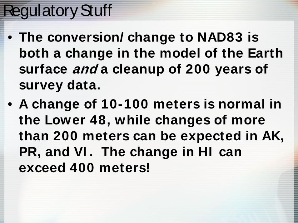
• The conversion/change to NAD83 is both a change in the model of the Earth surface and a cleanup of 200 years of survey data.
• A change of 10-100 meters is normal in the Lower 48, while changes of more than 200 meters can be expected in AK, PR, and VI. The change in HI can exceed 400 meters!

Regulatory Stuff
• The shifts between the two datums are not uniform across the United States.
• There is no single conversion factor available.
• Various software packages have been developed to facilitate this conversion.
• Google “NADCON” if you wish to download your own utility.

Regulatory Stuff
• A minor change in a densely populated area could affect your interference protection and service area.
• Have your tower surveyed if you are in doubt. Establish coordinates, site elevation, and antenna heights. Use a registered land surveyor to accomplish this.

Regulatory Stuff
• Be sure to have the surveyor specify what datum is being utilized.
• Note that WGS84 and NAD83 are synonymous.
• Have your coordinates surveyed down to at least tenths of a second.
• Establish heights accurately as the center of radiation AMSL is just as important as the coordinates.
• Correct variances with FAA and FCC.

Regulatory Stuff
• The Commission will apparently continue to require Automated Marine Telecommunications System licensees to protect authorizations on channels 10 and 13.
• This issue only affects stations near waterways. Very few channel 10 and channel 13 authorizations will be affected by AMTS.

Some Stuff about Coverage

Coverage Stuff
• In Reality Engineering in 2005, we discussed some of the considerations pertinent to your DTV Service Area and DTV “Coverage Area”.
• We will briefly revisit this topic for emphasis in light of the issuance of the recent table of allotments.

Coverage Stuff
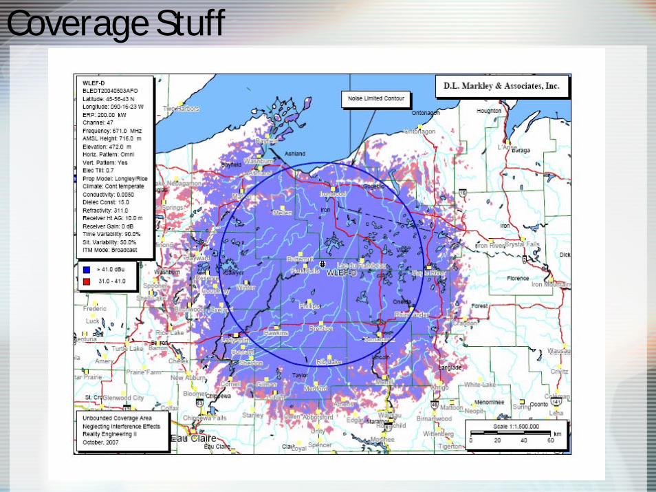
• The Commission defines the DTV service area as the interference-free area determined by Longley-Rice bounded by the noise-limited service contour.
• This is the service area to which you will be protected.
• In reality, you may be able to expect your coverage to extend further in practicality.

Coverage Stuff
• When we create a coverage map, we consider viewers to be utilizing a dipole antenna.
• While this is a good approximation for proximate viewers, this method mayunderestimate your total viewership.
• Distant viewers typically will have outdoor antennas. This gives them and you potential opportunities.

Coverage Stuff
Coverage Stuff

Thank You!Additional Questions/Comments?
Jeremy D. RuckD.L. Markley & Associates, Inc.2104 West Moss AvenuePeoria, IL 61604(309) 673-7511 Office(309) 208-5691 [email protected]


![State of Augmented Reality, Virtual Reality and Mixed Reality · State of Augmented Reality, Virtual Reality and Mixed Reality [Microsoft Hololen] [Ready Player One] Augmented Reality](https://img.pdfslide.us/doc/110x75/5f82ab6da2d89130b90d78c7/state-of-augmented-reality-virtual-reality-and-mixed-reality-state-of-augmented.jpg)