Embed Size (px)
Citation preview

Real-time position and orientationmeasurement with occlusion handlingfor distributed optical large-scalemetrology systems
Zhexu LiuJigui ZhuLinghui YangShenghua YeJun WuBin Xue
Downloaded From: https://www.spiedigitallibrary.org/journals/Optical-Engineering on 17 Nov 2021Terms of Use: https://www.spiedigitallibrary.org/terms-of-use

Real-time position and orientation measurement withocclusion handling for distributed optical large-scalemetrology systems
Zhexu LiuJigui ZhuLinghui YangShenghua YeJun WuBin XueTianjin UniversityState Key Laboratory of Precision Measuring
Technology and InstrumentsTianjin 300072, ChinaE-mail: [email protected]
Abstract. Occlusion is a major problem for real-time position and orien-tation measurement with distributed optical large-scale metrology sys-tems. This paper presents two novel methods with occlusion handlingto address this issue, which should be used in combination for practicalapplications. These two approaches are based on the constraints estab-lished by three control points and six control points, respectively, andthen the position and orientation can be calculated through iterative opti-mization algorithms. In this paper, all the work is carried out by using theworkspace measuring and positioning system as a verification platform.The experimental results show that the orientation accuracies of thethree-point method and the six-point method are kept within 0.1 and0.04 deg, respectively, and the position accuracy exceeds 0.15 and0.08 mm. © The Authors. Published by SPIE under a Creative Commons Attribution 3.0Unported License. Distribution or reproduction of this work in whole or in part requires full attri-bution of the original publication, including its DOI. [DOI: 10.1117/1.OE.52.11.114101]
Subject terms: position and orientation measurement; occlusion handling; distrib-uted metrology system; optical large-scale metrology system; workspace measur-ing and positioning system.
Paper 131181 received Aug. 1, 2013; revised manuscript received Sep. 24, 2013;accepted for publication Oct. 18, 2013; published online Nov. 13, 2013.
1 IntroductionReal-time position and orientation measurement is an indis-pensable component of industrial large-scale metrology,particularly in applications such as robot positioning in auto-mated manufacture, large aerospace structures assembly, andautonomous guided vehicle navigation.1–4 Recently, opticalmeasurement technology, as an advanced means of measure-ment, is widely applied in modern large-scale industry withits portability, noncontact, high precision, and large measure-ment range. Considering the need for accurate, flexible, andefficient solutions of real-time large-scale position and ori-entation measurement, several distributed large-scale metrol-ogy systems5,6 based on optical techniques are currentlyavailable, ranging from digital photogrammetry,7,8 the indoorglobal positioning system (iGPS),9,10 to the workspace meas-uring and positioning system (wMPS).11 The operatingtheories of these distributed optical systems for positionand orientation measurement are essentially the same:having a series of measuring stations working cooperatively,the optical information is collected to determine the coordi-nates of a set of control points attached to the moving object;subsequently, the position and orientation of the object canbe calculated.12
It is intuitively clear that the basic problem to be solved iscoordinate measurement of a spatial point in the workspace.With regard to the distributed metrology systems mentionedpreviously, the coordinate of a spatial point is obtained byensuring that the optical information from two or more meas-uring stations is acquired. However, this requirement cannotbe satisfied in most cases because of the occlusion caused bymany factors, including the complex structure of the movingobject, the obstacles and physical obstructions in the workingvolume, and the limited field of view of the optical devices.
When occlusion occurs in practical applications, it is oftenthe case that we can get information from only one measur-ing station for each point and sometimes even none for somepoints. Consequently, measurement cannot be accomplished.
In order to overcome this problem, a lot of work hasbeen conducted and several alternative solutions havebeen proposed. A straightforward approach is to improvethe connectivity of the system through using a large numberof transmitting and receiving devices, but it is not a preferredselection according to the cost efficiency. Considering thecompromise among cost, system connectivity, and measure-ment accuracy, other methods have been presented to avoidocclusion through optimizing the deployment of the devices,which are based on a variety of optimal positioning algo-rithms.13–15 Although these optimal methods have the poten-tial to solve the problem, they all suffer because (1) thepreprocessing feature of them makes measurement complexand time-consuming, (2) when the trajectory of the movingobject is changed, these methods may not be available fortheir poor flexibility, and (3) most of the algorithms arestudied and developed on the basis of computer simulationswithout practical test in applications.
This paper presents two real-time position and orientationmeasurement methods with occlusion handling for distrib-uted optical large-scale metrology systems, which shouldbe used in combination for practical applications. All thework is carried out by using the wMPS as a verificationplatform in this paper. With the two proposed methods,three control points and six control points are used to estab-lish the constraints respectively. Then, the position andorientation measurement can be accomplished convenientlyand accurately even if occlusion occurs. In addition, since allthe processes are on-line, the proposed approaches do not
Optical Engineering 114101-1 November 2013/Vol. 52(11)
Optical Engineering 52(11), 114101 (November 2013)
Downloaded From: https://www.spiedigitallibrary.org/journals/Optical-Engineering on 17 Nov 2021Terms of Use: https://www.spiedigitallibrary.org/terms-of-use

need complex preprocessing procedure and also presentgood adaptability for trajectory adjustment.
This paper is organized as follows. In Sec. 2, the wMPS,as the verification platform, is described and its operatingfeatures are outlined. Section 3 describes the two proposedmethods for real-time position and orientation measurementwith occlusion handling, including the mathematical modeland the establishment of the constraints. In Sec. 4, experi-ment is performed to verify the feasibility and accuracy ofthe proposed method. At last, discussion and conclusionare given.
2 wMPS Technology and Operating FeaturesThe wMPS is a laser-based measurement device for large-scale metrology applications, which is developed by TianjinUniversity, China. As shown in Fig. 1, a typical setup ofthe wMPS is composed of transmitters, receivers, signal pro-cessors, a scale bar, and a terminal computer.
The transmitter consists of a rotating head and a stationarybase. With two line laser modules fixed on the rotating headand several pulsed lasers mounted around the stationarybase, the transmitter generates three optical signals: twofan-shaped planar laser beams rotating with the head andan omnidirectional laser strobe emitted by the pulsed laserssynchronously when the head rotates to a predefined positionof every cycle. The receiver captures the three signals andthen converts them into electrical signals through a photo-electrical sensor. The signal processor distinguishes betweenthe electrical signals obtained from different transmittersand then extracts the information of the laser planes fromthem. Subsequently, using wireless Ethernet, the informationis sent to the terminal computer to calculate the coordinatesof the receiver.
It is noteworthy that the locations of the transmittersshould be determined before the start of the measurement,which is a part of the setup procedure. This is achieved bya calibration algorithm known as bundle adjustment.16,17
With this algorithm, the positions and orientations of thetransmitters with respect to the global coordinate frame canbe calculated by using a calibrated scale bar. Once the systemsetup is completed, the measurement can be performed. Thetransmitters distributed around the working volume rotate atdifferent speeds to allow the signals from them to be differ-entiated. When the laser planes emitted from at least twotransmitters intersect at a receiver, the equations of the planes
are exactly known from the information captured by it. Thenthe coordinates of the receiver can be obtained by least-squares solution of these plane equations.
Compared with the iGPS, another instrument designed forlarge-scale metrology, the wMPS uses the same operatingmode, that is, distributed optical measurement based onrotary-laser scanning. But the measurement principles andthe mathematical models of them are essentially different.The iGPS is based on multiple angle measurements, whilethe wMPS discussed in this paper is based on multiplaneintersection. Nevertheless, they are both good selections forlarge-scale orientation and position measurement with somepowerful features, especially the multitasking capability.
In order to determine the position and orientation, theconventional method with the wMPS is measuring the globalcoordinates of three or more receivers attached to the movingobject simultaneously, which is based on the location prin-ciple of the wMPS. Then, the position and orientation ofthe object can be calculated directly through a mathematicalmethod such as quaternion algorithm.18,19 However, ifocclusion occurs during measurement, it is often the casethat the receivers cannot be located because they can capturesignals from only one or even none of the transmitters.Consequently, the conventional method is not feasible.Therefore, we present two methods with occlusion handlingto address this problem. The details will be described in thesection below.
3 Position and Orientation Measurement withOcclusion Handling
3.1 Measurement Schematic and MathematicalModel
The measurement schematic of the proposed methods is thesame as the conventional method, which is shown in Fig. 2.NðN ≥ 2Þ transmitters are distributed around the workingvolume to construct a measurement network, andMðM ≥ 3Þreceivers are integrated with the moving object to createa coordinate frame that moves with it. The coordinatesof these receivers in the object coordinate frame areprecalibrated.
According to the measurement schematic describedpreviously, the mathematical model constructed with the
Fig. 1 System configuration of the workspace measuring and posi-tioning system.
Fig. 2 Schematic of position and orientation measurement with theproposed methods.
Optical Engineering 114101-2 November 2013/Vol. 52(11)
Liu et al.: Real-time position and orientation measurement with occlusion handling. . .
Downloaded From: https://www.spiedigitallibrary.org/journals/Optical-Engineering on 17 Nov 2021Terms of Use: https://www.spiedigitallibrary.org/terms-of-use
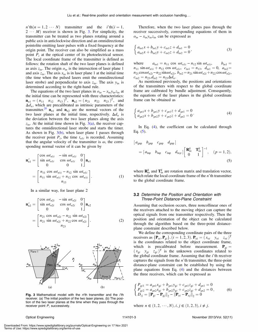
n’thðn ¼ 1; 2 · · · NÞ transmitter and the i’thði ¼ 1;2 · · · MÞ receiver is shown in Fig. 3. For simplicity, thetransmitter can be treated as two planes rotating around apublic axis in anticlockwise direction and an omnidirectionalpointolite emitting laser pulses with a fixed frequency at theorigin point. The receiver can also be simplified as a masspoint Pi at the optical center of its photoelectrical sensor.The local coordinate frame of the transmitter is defined asfollows: the rotation shaft of the two laser planes is definedas axis ztn. The origin otn is the intersection of laser plane 1and axis ztn. The axis xtn is in laser plane 1 at the initial time(the time when the pulsed lasers emit the omnidirectionallaser strobe) and perpendicular to axis ztn. The axis ytn isdetermined according to the right-hand rule.
The equations of the two laser planes in otn − xtnytnztn atthe initial time can be represented with three characteristics:nn1 ¼ ð n11 n12 n13 ÞT , nn2 ¼ ð n21 n22 n23 ÞT , andΔdn, which are precalibrated as intrinsic parameters of thetransmitter.20 nn1 and nn2 are the normal vectors of thetwo laser planes at the initial time, respectively. Δdn isthe deviation between the two laser planes along the axisztn. At the initial time shown in Fig. 3(a), the receiver cap-tures the omnidirectional laser strobe and starts the timer.As shown in Fig. 3(b), when laser plane 1 passes throughthe receiver point Pi, the time tn1i is recorded. Assumingthat the angular velocity of the transmitter is ω, the corre-sponding normal vector of it can be given by
n 0n1 ¼
"cos ωtn1i − sin ωtn1i 0
sin ωtn1i cos ωtn1i 0
0 0 1
#nn1
¼" n11 cos ωtn1i − n12 sin ωtn1in11 sin ωtn1i þ n12 cos ωtn1i
n13
#: (1)
In a similar way, for laser plane 2
n 0n2 ¼
"cos ωtn2i − sin ωtn2i 0
sin ωtn2i cos ωtn2i 0
0 0 1
#nn2
¼" n21 cos ωtn2i − n22 sin ωtn2in21 sin ωtn2i þ n22 cos ωtn2i
n23
#: (2)
Therefore, when the two laser planes pass through thereceiver successively, corresponding equations of them inotn − xtnytnztn can be expressed as
�atn1xþ btn1yþ ctn1zþ dtn1 ¼ 0
atn2xþ btn2yþ ctn2zþ dtn2 ¼ 0; (3)
where atn1 ¼ n11 cos ωtn1i − n12 sin ωtn1i, btn1 ¼n11 sinωtn1i þ n12 cos ωtn1i, ctn1 ¼ n13, dtn1 ¼ 0, atn2¼n21cosωtn2i−n22 sinωtn2i, btn2¼n21 sinωtn2iþn22 cosωtn2i,ctn2 ¼ n23,dtn2 ¼ n23Δdn.
As mentioned previously, the positions and orientationsof the transmitters with respect to the global coordinateframe are calibrated by bundle adjustment. Consequently,the equations of the laser planes in the global coordinateframe can be obtained as
�agn1xþ bgn1yþ cgn1zþ dgn1 ¼ 0
agn2xþ bgn2yþ cgn2zþ dgn2 ¼ 0: (4)
In Eq. (4), the coefficient can be calculated throughEq. (5).
½ agnp bgnp cgnp dgnp �
¼ ½ atnp btnp ctnp dtnp ��Rg
tn Tgtn
0 1
�−1; ðp ¼ 1; 2Þ;
(5)
where Rgtn and Tg
tn are rotation matrix and translation vector,which relate the local coordinate frame of the n’th transmitterto the global coordinate frame.
3.2 Determine the Position and Orientation withThree-Point Distance-Plane Constraint
Assuming that occlusion occurs, three noncollinear ones ofthe receivers attached to the moving object can capture theoptical signals from one transmitter respectively. Then theposition and orientation of the object can be calculatedthrough the algorithm based on the three-point distance-plane constraint described below.
We define the corresponding coordinate pairs of the threereceivers as fPoi;Pgig; ði ¼ 1; 2; 3Þ. Poi ¼ ð xoi yoi zoi ÞTis the coordinates related to the object coordinate frame,which is precalibrated before measurement. Pgi ¼ð xgi ygi zgi ÞT is the unknown coordinates related tothe global coordinate frame. Assuming that the i’th receivercaptures the signals from the n’th transmitter, the three-pointdistance-plane constraint can be established by using theplane equations from Eq. (4) and the distances betweenthe three receivers, which can be expressed as
(Pgi1 ¼ agn1xgi þ bgn1ygi þ cgn1zgi þ dgn1 ¼ 0
Pgi2 ¼ agn2xgi þ bgn2ygi þ cgn2zgi þ dgn2 ¼ 0
Dij ¼ kPgi − Pgjk2 − kPoi − Pojk2 ¼ 0; (6)
where n ∈ ð1; 2; · · · ; NÞ; i; j ∈ ð1; 2; 3Þ; i ≠ j.
Fig. 3 Mathematical model with the n’th transmitter and the i ’threceiver. (a) The initial position of the two laser planes. (b) The posi-tion of the two laser planes at the time when they pass through thereceiver point Pi successively.
Optical Engineering 114101-3 November 2013/Vol. 52(11)
Liu et al.: Real-time position and orientation measurement with occlusion handling. . .
Downloaded From: https://www.spiedigitallibrary.org/journals/Optical-Engineering on 17 Nov 2021Terms of Use: https://www.spiedigitallibrary.org/terms-of-use

From Eq. (6), we can make an optimal objective function.
E ¼X3i¼1
ðP2gi1 þ P2
gi2Þ þX3i¼1
X3j¼1j≠i
D2ij ¼ min : (7)
The coordinates of the three receivers can be obtained bysolving Eq. (7), and then the position and orientation of theobject can be calculated by using a mathematical methodknown as quaternion algorithm.18,19 For this nonlinearobjective function, Eq. (7) should be solved by an iterativeoptimization method such as Levenberg–Marquardt algo-rithm.21,22 The problem of initial value selection then arises.In order to overcome this problem, we use the coordinates ofthe three points measured at the moment before occlusionoccurs as the initial value for the first measurement, andthen during occlusion the earlier result obtained by the pro-posed method can be used as the initial value for the nextmeasurement.
3.3 Determine the Position and Orientation withSix-Point Multiplane Constraint
The method described above has presented a convenient sol-ution based on the three-point distance-plane constraint.However, it does not work for all cases. If occlusion exists
in the whole working volume constantly, the initial value ofthe iterative process cannot be determined, and the three-point method will be unavailable. Therefore, we proposeanother method based on the six-point multiplane constraintto address this issue. The requirement of this method is thatsix of the receivers attached to the moving object can capturethe optical signals from one transmitter respectively.
Similar to the three-point method, we define the corre-sponding coordinate pairs of the six receivers as fPoi;Pgig;ði ¼ 1; 2 · · · 6Þ. Then the position and orientation of themoving object can be given by
Pgi ¼ RgoPoi þ Tg
o; (8)
where
Rgo ¼
" r1 r2 r3r4 r5 r6r7 r8 r9
#
is the rotation matrix of the object coordinate framewith respect to the global coordinate frame, and Tg
o ¼ð tx ty tz ÞT is the translation vector.
Assuming that the i’th receiver captures the signals fromthe n’th transmitter, the six-point multiplane constraint canbe established by substituting Eq. (8) into Eq. (4).
8>><>>:
Pgi1 ¼ agn1xoir1 þ agn1yoir2 þ agn1zoir3 þ bgn1xoir4 þ bgn1yoir5 þ bgn1zoir6þcgn1xoir7 þ cgn1yoir8 þ cgn1zoir9 þ agn1tx þ bgn1ty þ cgn1tz þ dgn1 ¼ 0
Pgi2 ¼ agn2xoir1 þ agn2yoir2 þ agn2zoir3 þ bgn2xoir4 þ bgn2yoir5 þ bgn2zoir6þcgn2xoir7 þ cgn2yoir8 þ cgn2zoir9 þ agn2tx þ bgn2ty þ cgn2tz þ dgn2 ¼ 0
; (9)
where n ∈ ð1; 2; · · · NÞ, i · · · ð1; 2; · · · 6Þ.The Rg
o and Tgo to be determined include 12 unknown
parameters. From Eq. (9), each receiver gives two equations.Therefore, the Rg
o and Tgo can be determined by the solution
of the linear equations provided by the six receivers.However, in practical applications, Rg
o determined withthis method does not in general satisfy the orthogonal con-straint condition. Thus, we consider Eq. (9) and the orthogo-nal constraint of Rg
o.
8>>>>>><>>>>>>:
f1 ¼ r21 þ r22 þ r23 − 1 ¼ 0
f2 ¼ r24 þ r25 þ r26 − 1 ¼ 0
f3 ¼ r27 þ r28 þ r29 − 1 ¼ 0
f4 ¼ r1r4 þ r2r5 þ r3r6 ¼ 0
f5 ¼ r1r7 þ r2r8 þ r3r9 ¼ 0
f6 ¼ r4r7 þ r5r8 þ r6r9 ¼ 0
: (10)
To make an optimal objective function,
E ¼X6i¼1
ðP2gi1 þ P2
gi2Þ þMX6j¼1
f2j ¼ min; (11)
where M is the penalty factor. Minimizing Eq. (11) is anonlinear minimization problem, which can be solved by
using an iterative optimization method like Levenberg–Marquardt algorithm.21,22 The initial value for the iterativemethod can be calculated through the linear solutionof Eq. (9).
4 Experiment and ResultsAccording to recent study,11 the wMPS can presenthigh accuracy for coordinate measurement in a largevolume. As an off-the-shelf device, it has been success-fully used in industrial applications for real-time targetdetection with the conventional method.23 Therefore,a comparison experiment is conducted with the wMPSbetween the conventional method and the proposedmethods.
4.1 Setup of the Verification Platform
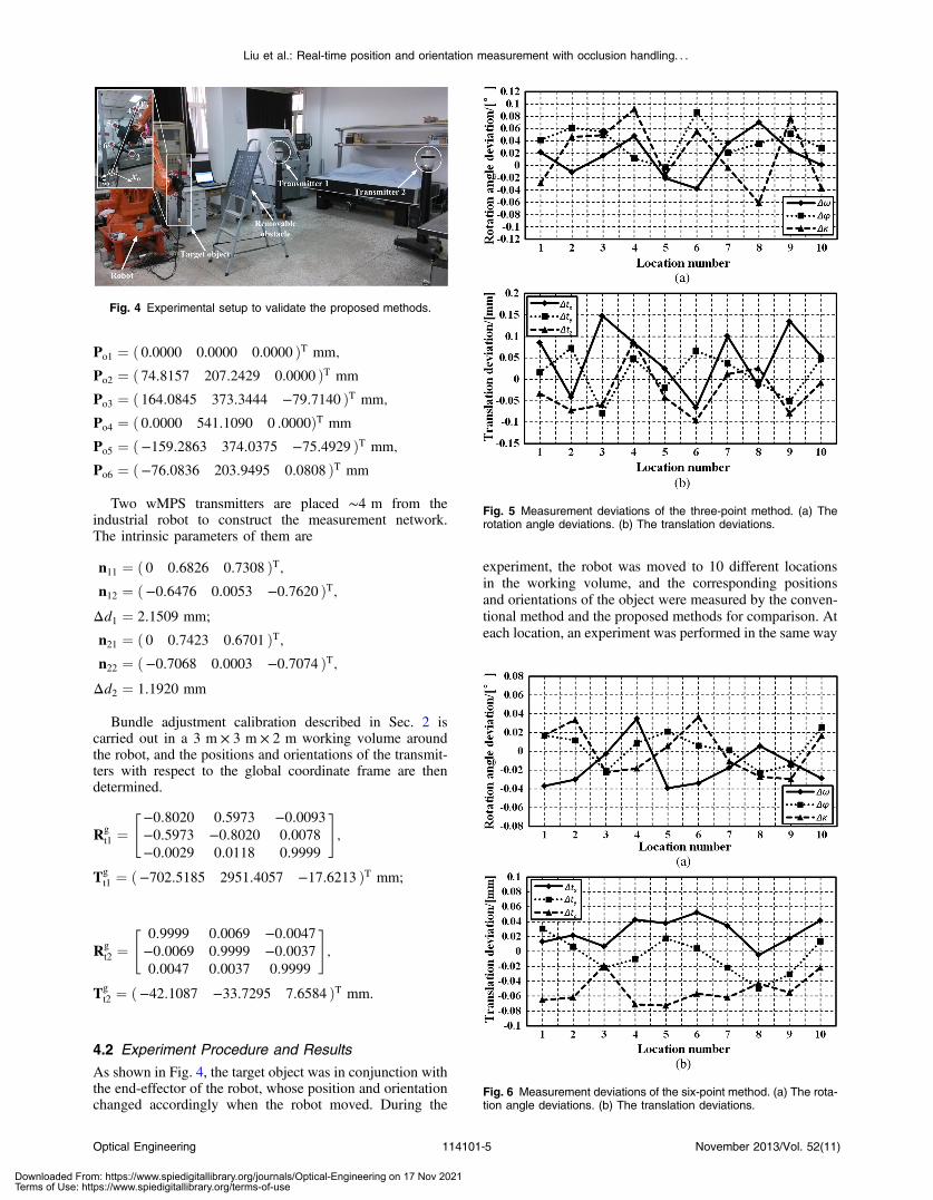
The experimental setup used to validate the proposed meth-ods is shown in Fig. 4.
As illustrated in Fig. 4, a target object is used in theexperiment, whose position and orientation are measuredfor comparison. Six receivers are fixed on the object toprovide a coordinate frame for it, and the coordinates ofthe receivers in this coordinate frame were experimentallyidentified using a precision coordinate measurementmachine.
Optical Engineering 114101-4 November 2013/Vol. 52(11)
Liu et al.: Real-time position and orientation measurement with occlusion handling. . .
Downloaded From: https://www.spiedigitallibrary.org/journals/Optical-Engineering on 17 Nov 2021Terms of Use: https://www.spiedigitallibrary.org/terms-of-use
Po1 ¼ ð 0.0000 0.0000 0.0000 ÞT mm;
Po2 ¼ ð 74:8157 207:2429 0.0000 ÞT mm
Po3 ¼ ð 164:0845 373:3444 −79:7140 ÞT mm;
Po4 ¼ ð 0:0000 541:1090 0 :0000ÞT mm
Po5 ¼ ð−159:2863 374:0375 −75:4929 ÞT mm;
Po6 ¼ ð−76:0836 203:9495 0:0808 ÞT mm
Two wMPS transmitters are placed ∼4 m from theindustrial robot to construct the measurement network.The intrinsic parameters of them are
n11 ¼ ð 0 0:6826 0:7308 ÞT;n12 ¼ ð−0:6476 0:0053 −0:7620 ÞT;Δd1 ¼ 2:1509 mm;
n21 ¼ ð 0 0:7423 0:6701 ÞT;n22 ¼ ð−0:7068 0:0003 −0:7074 ÞT;Δd2 ¼ 1:1920 mm
Bundle adjustment calibration described in Sec. 2 iscarried out in a 3 m × 3 m × 2 m working volume aroundthe robot, and the positions and orientations of the transmit-ters with respect to the global coordinate frame are thendetermined.
Rgt1 ¼
"−0:8020 0:5973 −0:0093−0:5973 −0:8020 0:0078−0:0029 0:0118 0:9999
#;
Tgt1 ¼ ð−702:5185 2951:4057 −17:6213 ÞT mm;
Rgt2 ¼
"0:9999 0:0069 −0:0047−0:0069 0:9999 −0:00370:0047 0:0037 0:9999
#;
Tgt2 ¼ ð−42:1087 −33:7295 7:6584 ÞT mm.
4.2 Experiment Procedure and Results
As shown in Fig. 4, the target object was in conjunction withthe end-effector of the robot, whose position and orientationchanged accordingly when the robot moved. During the
experiment, the robot was moved to 10 different locationsin the working volume, and the corresponding positionsand orientations of the object were measured by the conven-tional method and the proposed methods for comparison. Ateach location, an experiment was performed in the same way
Fig. 4 Experimental setup to validate the proposed methods.
Fig. 5 Measurement deviations of the three-point method. (a) Therotation angle deviations. (b) The translation deviations.
Fig. 6 Measurement deviations of the six-point method. (a) The rota-tion angle deviations. (b) The translation deviations.
Optical Engineering 114101-5 November 2013/Vol. 52(11)
Liu et al.: Real-time position and orientation measurement with occlusion handling. . .
Downloaded From: https://www.spiedigitallibrary.org/journals/Optical-Engineering on 17 Nov 2021Terms of Use: https://www.spiedigitallibrary.org/terms-of-use

by using a removable obstacle. First, without the obstacle,each receiver captured the signals from both transmitters,and the position and orientation of the object were recordedby the conventional method as a reference. After that, withthe robot keeping still, we placed the obstacle between thetransmitters and the object to simulate occlusion in practicalapplications. Optical signals from the transmitters to thereceivers were partially interrupted by the obstacle, andthe position and orientation of the object were then measuredby using the three-point method with receivers 1, 3, 5 and thesix-point method with all six receivers.
The position and orientation of the object are given bythe translation vector Tg
o ¼ ð tx ty tz ÞT and the rotationmatrix Rg
o, which relate the object coordinate frame to theglobal coordinate frame. In order to compare the resultsintuitively, Rg
o is represented by three single rotation anglesas usual, which are pitch ω, yaw φ, and roll κ. Then, the devi-ations between the positions and orientations measured bythe two proposed methods and the conventional methodare shown in Figs. 5 and 6, respectively.
As we can see from Fig. 5, the deviations of the rotationangles with the three-point method are kept within 0.1 deg,
and the position accuracy exceeds 0.15 mm. Also, fromFig. 6, the orientation accuracy and position accuracy ofthe six-point method exceed 0.04 deg and 0.08 mm, respec-tively. The experimental results demonstrate that the pro-posed methods are entirely feasible when occlusion occursand also exhibit good accuracy.
Another experiment was also designed to compare themeasurement results for both methods when the obstacleis removed. Without the obstacle, we controlled the robotto make it move to 10 different locations in the workingvolume. At each location, the corresponding positions andorientations of the object were measured by the three-pointmethod with receivers 1, 3, 5 and the six-point method withall six receivers, and then compared with the ground truthobtained by the conventional method. The comparisonresults are shown in Figs. 7 and 8.
From Figs. 7 and 8, it is clear that when the obstacle isremoved, we come to the same conclusion as the measure-ment results with the obstacle. Furthermore, it is worthyto note that the accuracy of the six-point method is superiorto the three-point method, which is caused by the redundantdata provided by more control points.
Fig. 7 Comparison of the orientation measurement of the two meth-ods: (a) the pitch deviations, (b) the yaw deviations, and (c) the rolldeviations.
Fig. 8 Comparison of the position measurement of the two methods:(a) the t x translation deviations, (b) the t y translation deviations, and(c) the t z translation deviations.
Optical Engineering 114101-6 November 2013/Vol. 52(11)
Liu et al.: Real-time position and orientation measurement with occlusion handling. . .
Downloaded From: https://www.spiedigitallibrary.org/journals/Optical-Engineering on 17 Nov 2021Terms of Use: https://www.spiedigitallibrary.org/terms-of-use
5 DiscussionConcerning the two methods proposed in this paper, there aresome issues to be discussed as below.
1. The two methods are appropriate to different casesbecause of their individual characteristics. The three-point method needs less control points, but it will beunavailable if occlusion exists in the whole workingvolume constantly because the iterative initial valuecannot be determined. The six-point method is notlimited by the condition of occlusion, but more controlpoints should be used. Furthermore, from the experi-mental results, the accuracy of the six-point methodis superior to the three-point method due to the redun-dant data provided by more control points. Therefore,in practical applications, these two methods shouldbe used in combination for an efficient compromiseamong the number of available control points, thefeasibility of the mathematical calculation, and themeasurement accuracy.
2. With regard to these two methods, it is worthy to notethat if redundant data are obtained from more controlpoints, we can reduce uncertainty and achieve a highermeasurement precision.
3. The proposed methods can also be applied to distrib-uted optical large-scale measurement systems otherthan wMPS, such as iGPS and stereo vision system,by simply changing the communication model andthe constraint equations.
6 ConclusionsTwo real-time position and orientation measurement meth-ods with occlusion handling have been presented fordistributed optical large-scale measurement systems, whichshould be used in combination for practical applications.These techniques are based on the constraints establishedby three control points and six control points, respectively,and the measurement principles are expounded in detail. Thefeasibility and accuracy of the proposed methods are verifiedby comparing the results of position and orientation meas-urement with the conventional method. The experimentreveals that the orientation deviations of the three-pointmethod and the six-point method are kept within 0.1 and0.04 deg, respectively, and the position accuracy exceeds0.15 and 0.08 mm. It clearly demonstrates that the methodsare feasible and also exhibit good accuracy. The proposedapproaches address the occlusion problem of the conven-tional position and orientation measurement method, andexpand the actual application of distributed optical large-scale measurement systems.
AcknowledgmentsThis work was funded by the National Natural ScienceFunds of China (51225505) and the National High-Technol-ogy & Development Program of China (863 Program,2012AA041205). The authors would like to express theirsincere appreciation to them, and comments from thereviewers and the editor were very much appreciated.
References
1. J. Hefele and C. Brenner, “Robot pose correction using photogrammet-ric tracking,” Proc. SPIE 4189, 170–178 (2001).
2. N. Jayaweera and P. Webb, “Metrology-assisted robotic processing ofaerospace applications,” Int. J. Comput. Integr. Manuf. 23(3), 283–296(2010).
3. W. W. Zhang, B. H. Zhuang, and Y. Zhang, “Novel navigation sensorfor autonomous guide vehicle,” Opt. Eng. 39(9), 2511–2516 (2000).
4. N. Morales et al., “Real-time adaptive obstacle detection based on animage database,” Comput. Vis. Image. Underst. 115(9), 1273–1287(2011).
5. F. Franceschini et al., Distributed Large-Scale Dimensional Metrology:New Insights, Springer, London (2011).
6. W. Cuypers et al., “Optical measurement techniques for mobile andlarge-scale dimensional metrology,” Opt. Laser Eng. 47(3), 292–300(2009).
7. C. Reich, R. Ritter, and J. Thesing, “3-D shape measurement of complexobjects by combining photogrammetry and fringe projection,”Opt. Eng.39(1), 224–231 (2000).
8. D. H. Zhang et al., “Exploitation of photogrammetry measurementsystem,” Opt. Eng. 49(3), 037005 (2010).
9. G. Mosqueira et al., “Analysis of the indoor GPS system as feedback forthe robotic alignment of fuselages using laser radar measurements ascomparison,” Robot. Copmut. Integr. Manuf. 28(6), 700–709 (2012).
10. A. R. Norman et al., “Validation of iGPS as an external measurementsystem for cooperative robot positioning,” Int. J. Adv. Manuf. Technol.64(1–4), 427–446 (2013).
11. Z. Xiong et al., “Workspace measuring and positioning system based onrotating laser planes,” Mechanika 18(1), 94–98 (2012).
12. Z. Zhang et al., “Improved iterative pose estimation algorithm usingthree-dimensional feature points,” Opt. Eng. 46(12), 127202 (2007).
13. M. Galetto and B. Pralio, “Optimal sensor positioning for large scalemetrology applications,” Precis. Eng. 34(3), 563–577 (2010).
14. F. Franceschini et al., “A review of localization algorithms for distrib-uted wireless sensor networks in manufacturing,” Int. J. Comput. Integr.Manuf. 22(7), 698–716 (2009).
15. M. Laguna et al., “Diversified local search for the optimal layout of bea-cons in an indoor positioning system,” IIE Trans. 41(3), 247–259 (2009).
16. B. Triggs et al., “Bundle adjustment—a modern synthesis,” in Proc. ofthe Int. Workshop on Vision Algorithms: Theory and Practice, pp. 298–372, Springer-Verlag, London (2000).
17. Y. Jeong et al., “Pushing the envelope of modern methods for bundleadjustment,” IEEE Trans. Pattern Anal. 34(8), 1605–1617 (2012).
18. B. K. P. Horn, “Closed form solution of absolute orientation using unitquaternions,” J. Opt. Soc. Am. A 4(4), 629–642 (1987).
19. M. Y. Liu et al., “Fast object localization and pose estimation in heavyclutter for robotic bin picking,” Int. J. Robot. Res. 31(8), 951–973(2012).
20. D. B. Lao et al., “Optimization of calibration method for scanningplanar laser coordinate measurement system,” Opt. Precis. Eng. 19(4),870–877 (2011).
21. J. J. Moré, “The Levenberg-Marquardt algorithm: implementation andtheory,” Numer. Anal. 105–116 (1978).
22. R. Behling et al., “A Levenberg-Marquardt method with approximateprojections,” Comput. Optim. Appl., 1–22 (2013).
23. Z. Xiong et al., “Application of workspace measurement and position-ing system in aircraft manufacturing assembly,” Aeronaut. Manuf.Technol. 21(1), 60–62 (2011).
Zhexu Liu is a PhD candidate in precisionmeasuring technology and instruments atTianjin University, and he received his MSdegree in precision measuring technologyand instruments from Tianjin University in2011. His research interests are in photo-electric precision measuring and large-scalemetrology.
Jigui Zhu received his BS and MS degreesfrom the National University of Defense Sci-ence and Technology of China in 1991 and1994, and his PhD degree in 1997 fromTianjinUniversity, China. He is now a professor at theState Key Laboratory of Precision Measure-ment Technology and Instruments, TianjinUniversity. His research interests are focusedon laser and photoelectric measuring technol-ogy, such as industrial online measurementand large-scale precision metrology.
Optical Engineering 114101-7 November 2013/Vol. 52(11)
Liu et al.: Real-time position and orientation measurement with occlusion handling. . .
Downloaded From: https://www.spiedigitallibrary.org/journals/Optical-Engineering on 17 Nov 2021Terms of Use: https://www.spiedigitallibrary.org/terms-of-use

Linghui Yang received his PhD from TianjinUniversity in 2010. He is currently a lecturerat the State Key Laboratory of PrecisionMeasurement Technology and Instruments,Tianjin University. His research interests arefocused on photoelectric precision measur-ing and large-scale metrology.
Biographies and photographs of the other authors not available.
Optical Engineering 114101-8 November 2013/Vol. 52(11)
Liu et al.: Real-time position and orientation measurement with occlusion handling. . .
Downloaded From: https://www.spiedigitallibrary.org/journals/Optical-Engineering on 17 Nov 2021Terms of Use: https://www.spiedigitallibrary.org/terms-of-use