Embed Size (px)
Citation preview
Real-time Indoor Localization using Magnetic, Time ofFlight, and Signal Strength Inference Maps
Andrew SymingtonDept. of Electrical Engineering
University of California, LALos Angeles, California, US
Jan MedvesekDept. of Computer ScienceUniversity College London
London, [email protected]
Paul MartinDept. of Electrical Engineering
University of California, LALos Angeles, California, US
Mani SrivastavaDept. of Electrical Engineering
University of California, LALos Angeles, California, US
Stephen HailesDept. of Computer ScienceUniversity College London
London, [email protected]
ABSTRACTThis paper presents a localization system that fuses inertial,magnetic field strength (MAG), RF time of flight (ToF),and received signal strength (RSS) measurements to track apedestrian moving indoors in real time. Our method uses apose graph to model a pedestrian’s trajectory as a sequenceof discrete positions. Rather than using range predictionsdirectly in the pose graph, our approach draws values froma Gaussian Process (GP) inference map built in advancefrom training data. To improve scalability, our implementa-tion is divided into two separate threads. The first threaduses inertial measurements and Kalman filtering to producea series of displacement vectors. These displacements areforwarded to a second thread where they are inserted into apose graph along with ToF and RSS measurements. Finally,a gradient descent method is used to obtain the sensor tra-jectory that minimizes the sum squared difference betweenthe predicted and measured ToF, RSS and MAG values.
KeywordsIndoor localization, Pedestrian localization, Data fusion
1. INTRODUCTIONDespite considerable research efforts over the past decades,
indoor localization remains an unsolved problem. Althoughinertial dead reckoning can be used over short periods, itsposition error typically scales cubically with time. Alter-nate methods of localization use radio measurements be-tween mobile and fixed points, either through fingerprint-ing or range-based methods. However, the accuracy of suchapproaches is inherently limited by the complex non-lineareffect of clutter and noise on radio propagation.
Permission to make digital or hard copies of all or part of this work forpersonal or classroom use is granted without fee provided that copies arenot made or distributed for profit or commercial advantage and that copiesbear this notice and the full citation on the first page. To copy otherwise, torepublish, to post on servers or to redistribute to lists, requires prior specificpermission and/or a fee.IPSN April 13-17 2015, Seattle, WA, USACopyright 20XX ACM X-XXXXX-XX-X/XX/XX ...$15.00.
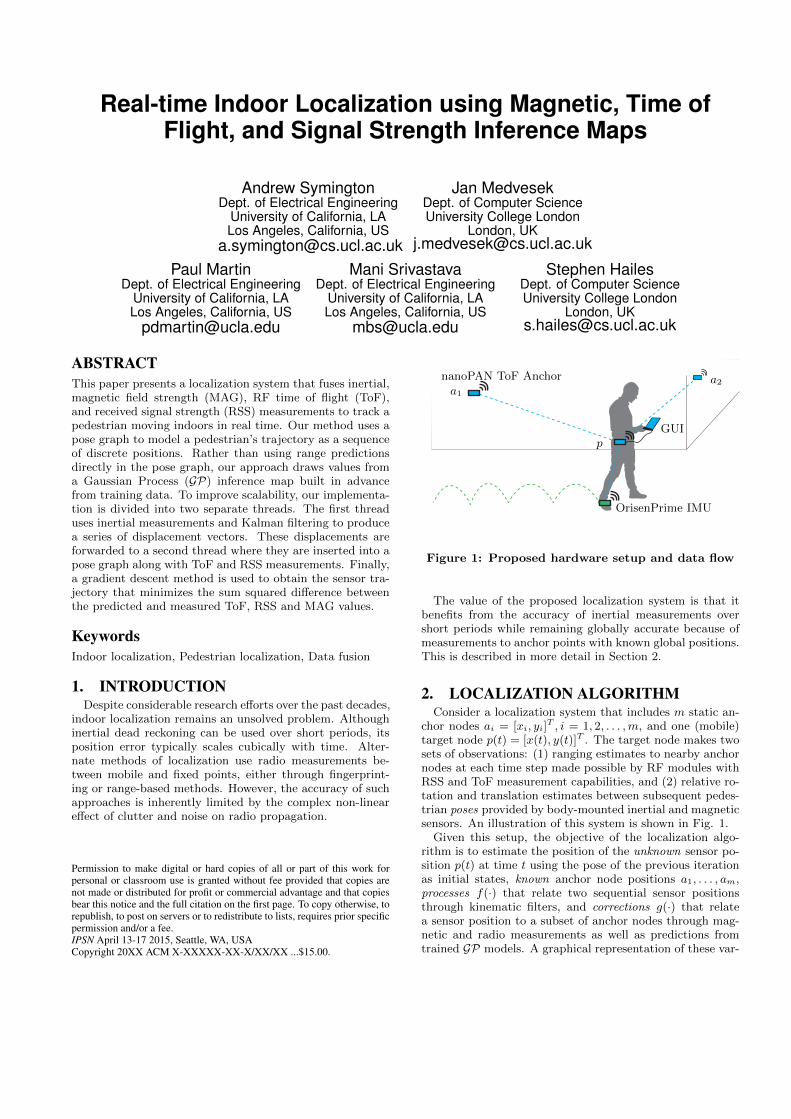
nanoPAN ToF Anchora1
a2
p
OrisenPrime IMU
GUI
Figure 1: Proposed hardware setup and data flow
The value of the proposed localization system is that itbenefits from the accuracy of inertial measurements overshort periods while remaining globally accurate because ofmeasurements to anchor points with known global positions.This is described in more detail in Section 2.
2. LOCALIZATION ALGORITHMConsider a localization system that includes m static an-
chor nodes ai = [xi, yi]T , i = 1, 2, . . . ,m, and one (mobile)
target node p(t) = [x(t), y(t)]T . The target node makes twosets of observations: (1) ranging estimates to nearby anchornodes at each time step made possible by RF modules withRSS and ToF measurement capabilities, and (2) relative ro-tation and translation estimates between subsequent pedes-trian poses provided by body-mounted inertial and magneticsensors. An illustration of this system is shown in Fig. 1.
Given this setup, the objective of the localization algo-rithm is to estimate the position of the unknown sensor po-sition p(t) at time t using the pose of the previous iterationas initial states, known anchor node positions a1, . . . , am,processes f(·) that relate two sequential sensor positionsthrough kinematic filters, and corrections g(·) that relatea sensor position to a subset of anchor nodes through mag-netic and radio measurements as well as predictions fromtrained GP models. A graphical representation of these var-
xt−3 xt−2 xt−1 xt
a1 a2 a3 am
GP1 GP2 GP3 GPk
ft−3(·) ft−2(·) ft−1(·)
gT
gRgT gR
gTgR
gT
gR gT
ggT ggRggMggT ggT
ggR ggR ggM
Figure 2: The localization problem expressed as apose graph, having measurements as edges
ious interacting components and processes in the proposedlocalization scheme is shown in Fig. 2.
Incorporating all inertial measurements into a single posegraph yields a representation with a solution complexitythat scales poorly with time. For this reason our imple-mentation is divided into two threads. The first thread ex-ecutes 6DoF kinematic tracking filter that estimates a rel-ative displacement vectors from high frequency inertial andmagnetic measurements. The second thread builds a coarse3D-embeddable pose-graph, and runs slower than the firstthread due to lower-frequency ToF and RSS measurements.An architectural overiew of our algorithm is given in Fig. 3.
Thread 1 - T1 > 100Hz
Thread 2 - T2 < 10Hz
Read IMU6DoF kinematic filter
PositionVelocityOrientation
Read ToF and RSS
Read pos., vel., ori., from T1
Pose-graph NLLS solver
Show the localization results
Figure 3: Localization algorithm overview
2.1 Thread 1 - Kinematic FilterThe mobile sensor implements a linearized version of the
Extended Kalman Filter (EKF) to perform inertial pedes-trian dead reckoning. Standard 6DoF rigid body kinematics[2] is used to propagate the navigation-frame position for-ward in time, given body-frame angular velocity and linearacceleration in a local frame. The filter also includes sen-sor bias states to model in-run sensor drift. A double inte-gration of acceleration measurements inherently causes highpositional error with respect to time, and so the localizationsystem periodically corrects the state estimate.
2.2 Thread 2 - Pose-graph SolverThe main structure of the proposed pose-graph localiza-
tion solver is an example of a robustified, non-linear leastsquares problem of the form: min
x
12
∑i
‖fi (xi1 , . . . , xik ) ‖2.
The optimization problem that needs to be solved can bedefined as the objective function shown in (1)
X̄ = arg minX
∑i∈M
(zi − hi(X))R−1i (zi − hi(X)) (1)
where X = {xi, i = t−∆t, . . . , t} contains unknown sensorpositions in a selected time window ∆t, zi are observations,
hi(·) is the measurement model, and Ri is the measurementnoise covariance. The processes f(·) obtained from the kine-matic filter and the corrections g(·) are bundled into a set ofmeasurements M . The measurement model hi(·) for the ithmeasurement extracts the relevant states from X to predictthe measurement value. A residual is then calculated usingthe observation zi and measurement noise covariance Ri [1].
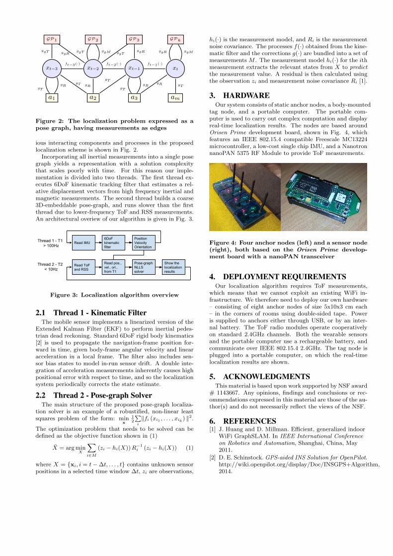
3. HARDWAREOur system consists of static anchor nodes, a body-mounted
tag node, and a portable computer. The portable com-puter is used to carry out complex computation and displayreal-time localization results. The nodes are based aroundOrisen Prime development board, shown in Fig. 4, whichfeatures an IEEE 802.15.4 compatible Freescale MC13224microcontroller, a low-cost single chip IMU, and a NanotronnanoPAN 5375 RF Module to provide ToF measurements.
Figure 4: Four anchor nodes (left) and a sensor node(right), both based on the Orisen Prime develop-ment board with a nanoPAN transceiver
4. DEPLOYMENT REQUIREMENTSOur localization algorithm requires ToF measurements,
which means that we cannot exploit an existing WiFi in-frastructure. We therefore need to deploy our own hardware– consisting of eight anchor nodes of size 5x10x3 cm each– in the corners of rooms using double-sided tape. Poweris supplied to anchors either through USB, or by an inter-nal battery. The ToF radio modules operate cooperativelyon standard 2.4GHz channels. Both the wearable sensorsand the portable computer use a rechargeable battery, andcommunicate over IEEE 802.15.4 2.4GHz. The tag node isplugged into a portable computer, on which the real-timelocalization results are shown.
5. ACKNOWLEDGMENTSThis material is based upon work supported by NSF award
# 1143667. Any opinions, findings and conclusions or rec-ommendations expressed in this material are those of the au-thor(s) and do not necessarily reflect the views of the NSF.
6. REFERENCES[1] J. Huang and D. Millman. Efficient, generalized indoor
WiFi GraphSLAM. In IEEE International Conferenceon Robotics and Automation, Shanghai, China, May2011.
[2] D. E. Schinstock. GPS-aided INS Solution for OpenPilot.http://wiki.openpilot.org/display/Doc/INSGPS+Algorithm,2014.