Embed Size (px)
Citation preview
This article has been accepted for publication in a future issue of this journal, but has not been fully edited. Content may change prior to final publication. Citation information: DOI 10.1109/TIE.2016.2542133, IEEETransactions on Industrial Electronics
IEEE TRANSACTIONS ON INDUSTRIAL ELECTRONICS
Abstract—In this paper a model predictive control (MPC) has
been designed and implemented on the Packed U-Cell (PUC)
inverter which has one isolated DC source and one capacitor as
an auxiliary DC link. The MPC is designed to regulate the
capacitor voltage at the desired magnitude to have seven voltage
levels at the output of the inverter. Since grid-connected
application is targeted by this application, the inverter should be
capable of supplying requested amount of active and reactive
power at the point of common coupling (PCC) as well. Therefore,
MPC should also consider the line current control in order to
monitor the exchange of reactive power with the grid while
injecting appropriate active power at low THD. Various
experimental tests including change in DC source voltage, active
power variation and operation at different power factor (PF)
have been performed on a laboratory prototype to validate the
good performance obtained by the proposed MPC. The dynamic
performance of the controller during sudden changes in dc
capacitor voltage, supply current and PF demonstrates the fast
and accurate response and the superior operation of the proposed
controller.
Index Terms—PUC Inverter, Multilevel Inverter, Model
Predictive Control, Grid-Connected PV, Power Quality.
I. INTRODUCTION
he global electrical energy consumption is estimated to rise on a positive slope for the coming years; therefore the
installed production capacity of classical high power stations may not be able to meet the ever increasing demand. Moreover, tolerating the conventional energy sources such as fossil fuel, nuclear and perhaps gas is becoming a social issue limiting possible implementations of such technology due to pollution impact and for safety consideration as well. In order to answer the ever growing energy demand, call for clean and renewable type of energy sources, to fill up the gap left by holding classical plant development, is answered by the industry which nowadays is developing commercial Solar, Wind, Biomass, and Geothermal [1, 2].
Manuscript received July 6, 2015; revised October 30, 2015 and January 14, 2016; accepted February 9, 2016. This work has been supported by the Agence Universitaire de la Francophonie (AUF), the Lebanese National Council for Scientific Research (CNRS-L), the Research Council of Saint-Joseph University, the Canadian Research Chair in Electric Energy Conversion and Power Electronics (CRC-EECPE) and the Natural Sciences and Engineering Research Council of Canada (NSERC).
J. Metri and H. Y. Kanaan are with the Saint-Joseph University of Beirut,Faculty of Engineering – ESIB, Beirut 1107-2050, Lebanon (e-mail: [email protected], [email protected]).
H. Vahedi and K. Al-Haddad are with the Ecole de TechnologieSuperieure, University of Quebec, Montreal, Quebec, Canada H3C 1K3 (email: [email protected], [email protected])
These sources have become an important asset of the world’s energy resources because of their non-polluting nature, little maintenance, at acceptable price. The solar cell behaves as a controlled current source which converts the irradiance energy directly into DC current. To convert the DC current/voltage into AC current/voltage while targeting high efficient scheme, less polluted with low emission of harmonics, power electronic converters are necessary; moreover, multilevel family type of converters are the most appropriate topologies to be considered [3-5].
Conventional inverters have some drawbacks like non sinusoidal output voltage rich in harmonic distortion (THD), high switching losses and thermal stress at high switching frequency with high level of common mode noise. Multilevel inverters constitute a class of devices which present interesting features that are naturally adapted to solar energy conversion schemes and therefore constitute an interesting solution to the proliferation of solar energy technology [6-8]. Multilevel inverters make use of switches and floating capacitors to produce various symmetrical voltage levels when controlled properly. The higher number of voltage levels produced, the lower is the harmonic content [9, 10]. Traditional multilevel inverters present many drawbacks though, they are costly and hard to implement when the number of voltage levels increases [11]. In order to attenuate the impact of such problems, several studies have been conducted and new multilevel inverters topologies have been proposed [12-18]. One promising topology is the Packed U-Cells (PUC) which combines advantages of flying capacitor (FC) and cascaded H-Bridges (CHB) and makes use of only one isolated DC source while the second DC bus should be regulated at a desired voltage level which influence the output voltage number of level [19, 20].
Several control techniques have been studied concerning the PUC like hysteresis current control [21], and nonlinear controllers [20, 22]. All those controllers have been implemented on the stand-alone inverter or rectifier application of the PUC topology. Therefore, they were mainly dealing with unity power factor operation as well as supplying power to the stand-alone loads. Moreover, adjusting multiple gains and using modulators to send the required switching pulses to the power electronic devices are the main drawbacks of the reported works.
Nowadays, power inverters are asked to provide both active and reactive power for the utility in which the grid voltage and current phase-shift as well as the current amplitude should be monitored and regulated online [23]. Though the idea of MPC was developed in 1960s [24], it remains simple and intuitive.
Real-Time Implementation of Model Predictive Control on 7-Level Packed U-Cell Inverter
Julie Metri, Hani Vahedi, Student, IEEE, Hadi Y. Kanaan, Senior Member, IEEE, Kamal Al-Haddad, Fellow, IEEE
T
© 2016 IEEE. Personal use of this material is permitted. Permission from IEEE must be obtained for all other uses, in any current or future media, including reprinting/republishing this material for advertising or promotional purposes, creating new collective works, for resale or redistribution to servers or lists, or reuse of any copyrighted component of this work in other works.
0278-0046 (c) 2015 IEEE. Personal use is permitted, but republication/redistribution requires IEEE permission. See http://www.ieee.org/publications_standards/publications/rights/index.html for more information.
This article has been accepted for publication in a future issue of this journal, but has not been fully edited. Content may change prior to final publication. Citation information: DOI 10.1109/TIE.2016.2542133, IEEETransactions on Industrial Electronics
IEEE TRANSACTIONS ON INDUSTRIAL ELECTRONICS
Comparing MPC to other classical controllers, a large number of calculations should be executed at each time step before sending the appropriate optimal signal to the devices. MPC consists of calculating the future behavior of the controlled variables, comparing them to their references, calculating a cost function that should be minimized in order to choose the optimal state. On the other hand, it features some interesting characteristics such as fast dynamic response, accurate tracking, and no gains to tune and no need to use an external type of modulators [25-31]. Some other research work dealt with studying the delay effect on MPC compensation performance as well [32].
In this paper, MPC is developed for the PUC inverter for grid-connected application. The PUC inverter has been studied and investigated as a renewable energy conversion device to deliver green power to the grid while generating multilevel voltage waveform with low harmonic contents at the ac output. Consequently, the PUC inverter capacitor voltage and the grid current should be controlled to have desired predefined power quality regulated voltage of the second DC bus as well as the desired operating Power Factor by changing the grid voltage and current phase-shift accordingly. The paper is organised as follow: after an Introduction to multilevel converters and MPC, section II includes the PUC topology description and switching sequences. MPC technique applied on the PUC inverter has been investigated and designed accurately and details are shown in section III. Experimental results are illustrated and discussed in section IV to validate the good dynamic performance of the proposed controller in controlling several parameters in the grid-connected system. Focus was put on operating condition changes that was performed to show the fast response of the designed controller in tracking the reference signal.
II. PACKED U-CELL TOPOLOGY AND
SWITCHING SEQUENCES
PUC converter has been introduced by Al-Haddad in 2011 [19, 22] and developed by Vahedi in 2015 [20, 33]. It can be used as single-phase converter as well as three-phase configuration. This topology is an intermediate hybridization of FC and CHB with reduced number of capacitors and semiconductors components. The general structure of the grid-connected PUC inverter is shown in Fig. 1. The inverter is connected to the grid through a line inductor (L) having a parasitic resistor (r). The line current is controlled to flow from the inverter to the grid with different phase angle proving therefore controlled active and reactive power at the Point of Common Coupling (PCC).
DC source and link amplitudes indicate the number of output voltage levels; using the 1/3 ratio leads to producing seven voltage level at the inverter output. Therefore, if V1 = 3V2 = 3E, then the output voltage waveform (Vinv) contains the voltage levels of 0, ±E, ±2E, ±3E.To reduce the number of isolated DC sources, an energy storage device (DC capacitor) is used at the second DC bus which needs voltage balancing methods like linear/nonlinear controllers or the advance
predictive control to fix the DC voltage accordingly. The voltage control method is explained in details in section III.
Fig. 1. 7-Level PUC Inverter in grid-connected application
TABLE I PUC SWITCHING STATES
States Sa Sb Sc VinvVinv
Value
1 1 0 0 V1 +3E
2 1 0 1 V1– V2 +2E
3 1 1 0 V2 +E
4 1 1 1 0 0
5 0 0 0 0 0
6 0 0 1 –V2 –E
7 0 1 0 V2– V1 –2E
8 0 1 1 –V1 –3E
PUC inverter consists of six active switches. Each switch can have two states, where switches S’
a, S’b and S’
c are working in complimentary with the associated switches of Sa, Sb and Sc. all switching states and corresponding voltage levels have been listed in table I. The use of 6 switches allows reaching eight switching states including two redundant ones.
Comparing to the CHB or FC topologies generating 7-level voltage, the PUC converter has less number of isolated DC sources, DC capacitors and switching devices. However, the main problem with this topology is the different voltage rating of switches. Fortunately, the upper two switches working at the fundamental frequency should suffer the highest voltage while the four lower switches that have higher switching frequency see the lower voltage which is compatible with semiconductor devices performances.
III. MODEL PREDICTIVE CONTROL
Different control methods for voltage balancing and current control exist such as linear/nonlinear controllers, predictive model, fuzzy, etc [33-37]. Model Predictive Control or MPC uses a model of the system to predict the future behavior of the variables [24, 27].One of the major advantages of the FCS-MPC compared to a traditional PI controller is the flexibility to control different variables, with constraints and additional
0278-0046 (c) 2015 IEEE. Personal use is permitted, but republication/redistribution requires IEEE permission. See http://www.ieee.org/publications_standards/publications/rights/index.html for more information.
This article has been accepted for publication in a future issue of this journal, but has not been fully edited. Content may change prior to final publication. Citation information: DOI 10.1109/TIE.2016.2542133, IEEETransactions on Industrial Electronics
IEEE TRANSACTIONS ON INDUSTRIAL ELECTRONICS
system requirements. Besides, using MPC avoids the cascade structure which implies inner faster dynamic loop and outer slower dynamic loop to control system parameters; such a scheme is typically used in a linear control. The drawbacks of FCS-MPC is that such a controller can operate at variable switching frequency and also It requires a high number of calculations to generate its output, compared to a classical continuous control scheme.
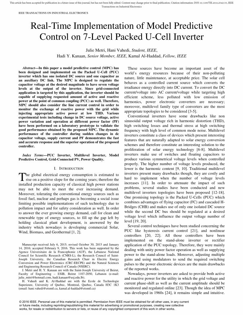
Fig. 2 presents a general scheme for MPC to control the grid-connected inverter. In general, MPC consists of measuring the variable and use it in the predictive control in order to calculate the future value + 1 of the controlled variable for each one of the switching states. Then, a cost function is calculated in order to choose the minimum value corresponding to the optimal state and apply it on the PUC inverter through the switching pulses. Switching pulses are produced according to the appropriate switching state chosen by the MPC from the recalculated switching table.
Fig. 2. General Scheme for MPC
Switches are considered ideal so they have only two states: ON or OFF. In this work, there are 7 possible switching states since two states generate same voltage (0 V).
The two variables that have to be controlled are the load current and the capacitor voltage V2. Therefore, to simplify the calculation, two new variables can be defined that reduce the computations. S1 and S2 are used in order to simplify the use of Sa, Sb and Sc states. They are calculated depending on Sa, Sb and Sc values by using the following equations (1) and (2):
1 a bS S S= − (1)
2 b cS S S= − (2)
TABLE II MODIFIED SWITCHING STATES BASED ON MPC
States S1 S2 Vinv
1 1 0 V1
2 1 -1 V1- V2
3 0 1 V2
4 0 0 0
5 0 -1 -V2
6 -1 1 V2- V1
7 -1 0 -V1
Table II shows different possible operating states of the
PUC by introducing two new variables S1 and S2. The voltage vector generated by the inverter is calculated
using equation (3).
1 1 2 2invV S V S V= + (3)
Concerning the capacitor voltage,
22 2 2 s
dVi C S i
dt= = − (4)
Using the Euler Forward Approximation, the capacitor voltage can be replaced by equation (5)
2 2 2( 1) ( )
s
dV V k V k
dt T
+ −= (5)
Where, Ts is the sampling time. Replacing (5) in (4), Eq. (6) can be obtained as the
following:
22 2
2
( 1) ( ) ( )ss
T SV k V k i k
C
×+ = − (6)
The load current dynamics can be described by the vector differential equation (7) as:
sinv s s
diV v r i L
dt= + × + × (7)
Using again the Euler Forward Approximation, the load current can be replaced by equation (8)
( 1) ( )s s s
s
di i k i k
dt T
+ −= (8)
Substituting (8) in (7) results in the Eq. (9):
( 1) (1 ) ( ) ( ( ) )s ss s inv s
r T Ti k i k V k v
L L
×
+ = − × + × − (9)
Finally, the cost function g is derived as Eq. (10):
* 2 * 21 2 2 2( ) ( ( ) ) ( ( ) )s sg k k i k i k V k V= − + − (10)
The cost function g is calculated for the 7 possible switching states, but S1 and S2 are chosen for the minimum value of g. Once S1 and S2 are generated, the switching state number will be determined using table II and then Sa, Sb and Sc are then selected based on table I to be sent to the PUC inverter switches.
The grid current and the capacitor voltage are measured for the instant k. Based on these values, v2(k+1), and is(k+1) are predicted using equations 6 and 9.The cost function at the same instant k, is calculated using the values of v2 and is at the instant k+1.Therefore, in order to simplify the cost function equation (10), it was mentioned for the instant k to just show its general form applicability.
0278-0046 (c) 2015 IEEE. Personal use is permitted, but republication/redistribution requires IEEE permission. See http://www.ieee.org/publications_standards/publications/rights/index.html for more information.
This article has been accepted for publication in a future issue of this journal, but has not been fully edited. Content may change prior to final publication. Citation information: DOI 10.1109/TIE.2016.2542133, IEEETransactions on Industrial Electronics
IEEE TRANSACTIONS ON INDUSTRIAL ELECTRONICS
k1 and k2 are two weighting factors, they are used to avoid coupling effects in case of using several variables in the cost function. Indeed, there are no analytical or numerical methods as such to adjust the weighting factors. In case of cost functions where there is only one variable to be controlled, there is no need for weighting factors. In this case, we have two variables to be controlled and they are equally important. At first one can normalize the cost function and set the factors equal to 1, and then change them in order to minimize the cost function. At least two different figures of merit or system parameters have to be considered, depending on the application [31].
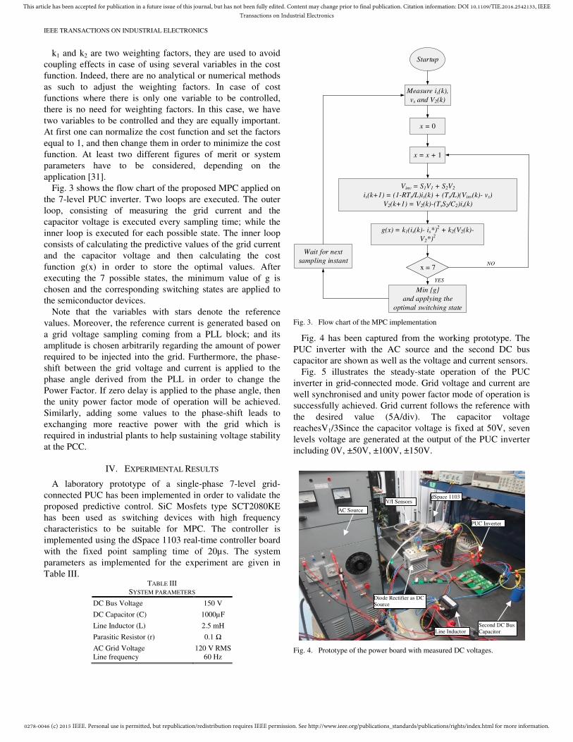
Fig. 3 shows the flow chart of the proposed MPC applied on the 7-level PUC inverter. Two loops are executed. The outer loop, consisting of measuring the grid current and the capacitor voltage is executed every sampling time; while the inner loop is executed for each possible state. The inner loop consists of calculating the predictive values of the grid current and the capacitor voltage and then calculating the cost function g(x) in order to store the optimal values. After executing the 7 possible states, the minimum value of g is chosen and the corresponding switching states are applied to the semiconductor devices.
Note that the variables with stars denote the reference values. Moreover, the reference current is generated based on a grid voltage sampling coming from a PLL block; and its amplitude is chosen arbitrarily regarding the amount of power required to be injected into the grid. Furthermore, the phase-shift between the grid voltage and current is applied to the phase angle derived from the PLL in order to change the Power Factor. If zero delay is applied to the phase angle, then the unity power factor mode of operation will be achieved. Similarly, adding some values to the phase-shift leads to exchanging more reactive power with the grid which is required in industrial plants to help sustaining voltage stability at the PCC.
IV. EXPERIMENTAL RESULTS
A laboratory prototype of a single-phase 7-level grid-connected PUC has been implemented in order to validate the proposed predictive control. SiC Mosfets type SCT2080KE has been used as switching devices with high frequency characteristics to be suitable for MPC. The controller is implemented using the dSpace 1103 real-time controller board with the fixed point sampling time of 20µs. The system parameters as implemented for the experiment are given in Table III.
TABLE III SYSTEM PARAMETERS
DC Bus Voltage 150 V
DC Capacitor (C) 1000µF
Line Inductor (L) 2.5 mH
Parasitic Resistor (r) 0.1 Ω
AC Grid Voltage Line frequency
120 V RMS 60 Hz
Startup
Measure is(k),
vs and V2(k)
x = 0
x = x + 1
g(x) = k1(is(k)- is*)2 + k2(V2(k)-
V2*)2
Vinv = S1V1 + S2V2
is(k+1) = (1-RTs/L)is(k) + (Ts/L)(Vinv(k)- vs)
V2(k+1) = V2(k)-(TsS2/C2)is(k)
YES
NO
Wait for next
sampling instant
Min g
and applying the
optimal switching state
x = 7
Fig. 3. Flow chart of the MPC implementation
Fig. 4 has been captured from the working prototype. The PUC inverter with the AC source and the second DC bus capacitor are shown as well as the voltage and current sensors.
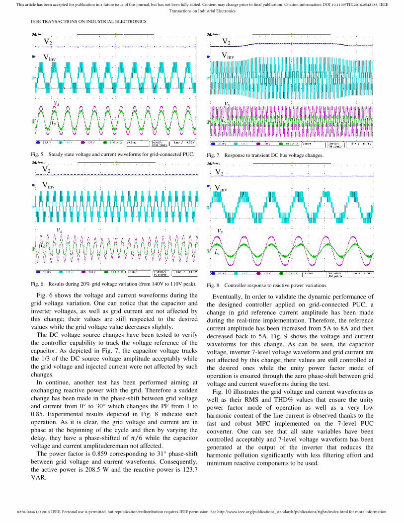
Fig. 5 illustrates the steady-state operation of the PUC inverter in grid-connected mode. Grid voltage and current are well synchronised and unity power factor mode of operation is successfully achieved. Grid current follows the reference with the desired value (5A/div). The capacitor voltage reachesV1/3Since the capacitor voltage is fixed at 50V, seven levels voltage are generated at the output of the PUC inverter including 0V, ±50V, ±100V, ±150V.
Fig. 4. Prototype of the power board with measured DC voltages.
AC Source
V/I Sensors dSpace 1103
Diode Rectifier as DC Source
PUC Inverter
Second DC Bus Capacitor Line Inductor
0278-0046 (c) 2015 IEEE. Personal use is permitted, but republication/redistribution requires IEEE permission. See http://www.ieee.org/publications_standards/publications/rights/index.html for more information.
This article has been accepted for publication in a future issue of this journal, but has not been fully edited. Content may change prior to final publication. Citation information: DOI 10.1109/TIE.2016.2542133, IEEETransactions on Industrial Electronics
IEEE TRANSACTIONS ON INDUSTRIAL ELECTRONICS
Fig. 5. Steady state voltage and current waveforms for grid-connected PUC.
Fig. 6. Results during 20% grid voltage variation (from 140V to 110V peak).
Fig. 6 shows the voltage and current waveforms during the grid voltage variation. One can notice that the capacitor and inverter voltages, as well as grid current are not affected by this change; their values are still respected to the desired values while the grid voltage value decreases slightly.
The DC voltage source changes have been tested to verify the controller capability to track the voltage reference of the capacitor. As depicted in Fig. 7, the capacitor voltage tracks the 1/3 of the DC source voltage amplitude acceptably while the grid voltage and injected current were not affected by such changes.
In continue, another test has been performed aiming at exchanging reactive power with the grid. Therefore a sudden change has been made in the phase-shift between grid voltage and current from 0° to 30° which changes the PF from 1 to 0.85. Experimental results depicted in Fig. 8 indicate such operation. As it is clear, the grid voltage and current are in phase at the beginning of the cycle and then by varying the delay, they have a phase-shifted of 6⁄ while the capacitor voltage and current amplituderemain not affected.
The power factor is 0.859 corresponding to 31° phase-shift between grid voltage and current waveforms. Consequently, the active power is 208.5 W and the reactive power is 123.7 VAR.
Fig. 7. Response to transient DC bus voltage changes.
Fig. 8. Controller response to reactive power variations.
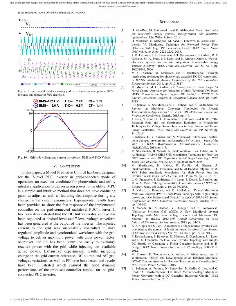
Eventually, In order to validate the dynamic performance of the designed controller applied on grid-connected PUC, a change in grid reference current amplitude has been made during the real-time implementation. Therefore, the reference current amplitude has been increased from 5A to 8A and then decreased back to 5A. Fig. 9 shows the voltage and current waveforms for this change. As can be seen, the capacitor voltage, inverter 7-level voltage waveform and grid current are not affected by this change; their values are still controlled at the desired ones while the unity power factor mode of operation is ensured through the zero phase-shift between grid voltage and current waveforms during the test.
Fig. 10 illustrates the grid voltage and current waveforms as well as their RMS and THD% values that ensure the unity power factor mode of operation as well as a very low harmonic content of the line current is observed thanks to the fast and robust MPC implemented on the 7-level PUC converter. One can see that all state variables have been controlled acceptably and 7-level voltage waveform has been generated at the output of the inverter that reduces the harmonic pollution significantly with less filtering effort and minimum reactive components to be used.
V2
Vinv
vs
is
V2
Vinv
vs
is
V2
Vinv
vs
is
V2
Vinv
vs
is
0278-0046 (c) 2015 IEEE. Personal use is permitted, but republication/redistribution requires IEEE permission. See http://www.ieee.org/publications_standards/publications/rights/index.html for more information.
This article has been accepted for publication in a future issue of this journal, but has not been fully edited. Content may change prior to final publication. Citation information: DOI 10.1109/TIE.2016.2542133, IEEETransactions on Industrial Electronics
IEEE TRANSACTIONS ON INDUSTRIAL ELECTRONICS
Fig. 9. Experimental results showing grid current reference amplitude 100% increase and thereafter 50% decrease.
Fig. 10. Grid side voltage and current waveforms, RMS and THD Values.
V. CONCLUSION
In this paper, a Model Predictive Control has been designed for the 7-level PUC inverter in grid-connected mode of operation, an excellent candidate for photovoltaic and utility interface application to deliver green power to the utility. MPC is a simple and intuitive method that does not have confusing gains to adjust as well as featuring fast response during any change in the system parameters. Experimental results have been provided to show the fast response of the implemented controller on the grid-connected multilevel PUC inverter. It has been demonstrated that the DC link capacitor voltage has been regulated at desired level and 7-level voltage waveform has been generated at the output of the inverter. The injected current to the grid was successfully controlled to have regulated amplitude and synchronized waveform with the grid voltage to deliver maximum power with unity power factor. Moreover, the PF has been controlled easily to exchange reactive power with the grid while injecting the available active power. Exhaustive experimental results including change in the grid current reference, DC source and AC grid voltages variations, as well as PF have been tested and results have been illustrated which ensured the good dynamic performance of the proposed controller applied on the grid-connected PUC inverter.
REFERENCES
[1] H. Abu-Rub, M. Malinowski, and K. Al-Haddad, Power electronics
for renewable energy systems, transportation and industrial
applications: John Wiley & Sons, 2014. [2] H. Mortazavi, H. Mehrjerdi, M. Saad, S. Lefebvre, D. Asber, and L.
Lenoir, "A Monitoring Technique for Reversed Power Flow Detection With High PV Penetration Level," IEEE Trans. Smart
Grid, vol. 6, no. 5, pp. 2221-2232, 2015. [3] J. M. Carrasco, L. G. Franquelo, J. T. Bialasiewicz, E. Galván, R. P.
Guisado, M. A. Prats, J. I. León, and N. Moreno-Alfonso, "Power-electronic systems for the grid integration of renewable energy sources: A survey," IEEE Trans. Ind. Electron., vol. 53, no. 4, pp. 1002-1016, 2006.
[4] M. G. Kashani, M. Mobarrez, and S. Bhattacharya, "Variable interleaving technique for photovoltaic cascaded DC-DC converters," in IECON 2014-40th Annual Conference of the IEE EIndustrial
Electronics Society, 2014, pp. 5612-5617. [5] M. Mobarrez, M. G. Kashani, G. Chavan, and S. Bhattacharya, "A
Novel Control Approach for Protection of Multi-Terminal VSC based HVDC Transmission System against DC Faults," in ECCE 2015-
Energy Conversion Congress & Exposition, Canada, 2015, pp. 4208-4213.
[6] P. Qashqai, A. Sheikholeslami, H. Vahedi, and K. Al-Haddad, "A Review on Multilevel Converter Topologies for Electric Transportation Applications " in VPPC 2015-Vehicular Power and
Propulsion Conference, Canada, 2015, pp. 1-6. [7] J. Leon, S. Kouro, L. G. Franquelo, J. Rodriguez, and B. Wu, "The
Essential Role and the Continuous Evolution of Modulation Techniques for Voltage Source Inverters in Past, Present and Future Power Electronics," IEEE Trans. Ind. Electron., vol. PP, no. 99, pp. 1-1, 2016.
[8] F. Sebaaly, H. Y. Kanaan, and N. Moubayed, "Three-level neutral-point-clamped inverters in transformerless PV systems—State of the art," in IEEE Mediterranean Electrotechnical Conference
(MELECON), 2014, pp. 1-7. [9] M. Sharifzadeh, H. Vahedi, A. Sheikholeslami, P.-A. Labbé, and K.
Al-Haddad, "Hybrid SHM-SHE Modulation Technique for Four-Leg NPC Inverter with DC Capacitors Self-Voltage-Balancing," IEEE
Trans. Ind. Electron., vol. 62, no. 8, pp. 4890-4899, 2015. [10] M. Sharifzadeh, H. Vahedi, R. Portillo, M. Khenar, A.
Sheikholeslami, L. G. Franquelo, and K. Al-Haddad, "Hybrid SHM-SHE Pulse Amplitude Modulation for High Power Four-Leg Inverter," IEEE Trans. Ind. Electron., vol. PP, no. 99, pp. 1-1, 2016.
[11] L. G. Franquelo, J. Rodriguez, J. I. Leon, S. Kouro, R. Portillo, and M. A. M. Prats, "The age of multilevel converters arrives," IEEE Ind.
Electron. Mag., vol. 2, no. 2, pp. 28-39, 2008. [12] H. Vahedi, S. Rahmani, and K. Al-Haddad, "Pinned Mid-Points
Multilevel Inverter (PMP): Three-Phase Topology with High Voltage Levels and One Bidirectional Switch," in IECON 2013-39th Annual
Conference on IEEE Industrial Electronics Society, Austria, 2013, pp. 100-105.
[13] H. Vahedi, K. Al-Haddad, Y. Ounejjar, and K. Addoweesh, "Crossover Switches Cell (CSC): A New Multilevel Inverter Topology with Maximum Voltage Levels and Minimum DC Sources," in IECON 2013-39th Annual Conference on IEEE
Industrial Electronics Society, Austria, 2013, pp. 54-59. [14] K. K. Gupta and S. Jain, "A multilevel Voltage Source Inverter (VSI)
to maximize the number of levels in output waveform," Int. Journal
of Electric. Power & Energy Sys., vol. 44, no. 1, pp. 25-36, 2013. [15] P. Roshankumar, P. Rajeevan, K. Mathew, K. Gopakumar, J. I. Leon,
and L. G. Franquelo, "A Five-Level Inverter Topology with Single-DC Supply by Cascading a Flying Capacitor Inverter and an H-Bridge," IEEE Trans. Power Electron., vol. 27, no. 8, pp. 3505-3512, 2012.
[16] M. Youssef, K. Woronowicz, K. Aditya, N. Abdul Azeez, and S. Williamson, "Design and Development of an Efficient Multilevel DC/AC Traction Inverter for Railway Transportation Electrification," IEEE Trans. Power Electron., 2015.
[17] L. Solomon, A. Permuy, N. Benavides, D. Opila, C. Lee, and G. Reed, "A Transformerless PCB Based Medium-Voltage Multilevel Power Converter with a DC Capacitor Balancing Circuit," IEEE
Trans. Power Electron., 2015.
V2
Vinv
vs
is
0278-0046 (c) 2015 IEEE. Personal use is permitted, but republication/redistribution requires IEEE permission. See http://www.ieee.org/publications_standards/publications/rights/index.html for more information.
This article has been accepted for publication in a future issue of this journal, but has not been fully edited. Content may change prior to final publication. Citation information: DOI 10.1109/TIE.2016.2542133, IEEETransactions on Industrial Electronics
IEEE TRANSACTIONS ON INDUSTRIAL ELECTRONICS
[18] M. Narimani, B. Wu, and N. Zargari, "A Novel Five-Level Voltage Source Inverter with Sinusoidal Pulse Width Modulator for Medium-Voltage Applications," IEEE Trans. Power Electron., 2015.
[19] K. Al-Haddad, Y. Ounejjar, and L. A. Gregoire, "Multilevel Electric Power Converter," US Patent 20110280052, Nov 2011.
[20] H. Vahedi and K. Al-Haddad, "Real-Time Implementation of a Packed U-Cell Seven-Level Inverter with Low Switching Frequency Voltage Regulator," IEEE Trans. Power Electron., vol. 31, no. 8, pp. 5967-5973, 2016.
[21] Y. Ounejjar, K. Al-Haddad, and L. A. Dessaint, "A Novel Six-Band Hysteresis Control for the Packed U Cells Seven-Level Converter: Experimental Validation," IEEE Trans. Ind. Electron., vol. 59, no. 10, pp. 3808-3816, 2012.
[22] Y. Ounejjar, K. Al-Haddad, and L. A. Grégoire, "Packed U cells multilevel converter topology: theoretical study and experimental validation," IEEE Trans. Ind. Electron., vol. 58, no. 4, pp. 1294-1306, 2011.
[23] Y. Yang, H. Wang, and F. Blaabjerg, "Reactive power injection strategies for single-phase photovoltaic systems considering grid requirements," IEEE Trans. Ind. Applications, vol. 50, no. 6, pp. 4065-4076, 2014.
[24] J. Rodriguez and P. Cortes, Predictive control of power converters
and electrical drives: John Wiley & Sons, 2012. [25] J. Barros, F. Silva, and E. Jesus, "Fast predictive optimal control of
NPC multilevel converters," IEEE Trans. Ind. Electron., vol. 60, no. 2, pp. 619 - 627, 2013.
[26] V. Yaramasu and B. Wu, "Model predictive decoupled active and reactive power control for high-power grid-connected four-level diode-clamped inverters," IEEE Trans. Ind. Electron., vol. 61, no. 7, pp. 3407-3416, 2014.
[27] S. Kouro, P. Cortés, R. Vargas, U. Ammann, and J. Rodríguez, "Model predictive control—A simple and powerful method to control power converters," IEEE Trans. Ind. Electron., vol. 56, no. 6, pp. 1826-1838, 2009.
[28] M. Rivera, A. Wilson, C. Rojas, J. Rodriguez, J. R. Espinoza, P. W. Wheeler, and L. Empringham, "A comparative assessment of model predictive current control and space vector modulation in a direct matrix converter," IEEE Trans. Ind. Electron., vol. 60, no. 2, pp. 578-588, 2013.
[29] M. Rivera, V. Yaramasu, J. Rodriguez, and B. Wu, "Model predictive current control of two-level four-leg inverters—Part II: Experimental implementation and validation," IEEE Trans. Power Electron., vol. 28, no. 7, pp. 3469-3478, 2013.
[30] P. Cortés, G. Ortiz, J. Yuz, J. Rodríguez, S. Vazquez, and L. G. Franquelo, "Model predictive control of an inverter with output filter for UPS applications," IEEE Trans. Ind. Electron., vol. 56, no. 6, pp. 1875-1883, 2009.
[31] S. Vazquez, J. Leon, L. G. Franquelo, J. Rodriguez, H. Young, A. Marquez, and P. Zanchetta, "Model predictive control: A review of its applications in power electronics," IEEE Ind. Electron. Mag., vol. 8, no. 1, pp. 16-31, 2014.
[32] P. Cortes, J. Rodriguez, C. Silva, and A. Flores, "Delay compensation in model predictive current control of a three-phase inverter," IEEE
Trans. Ind. Electron., vol. 59, no. 2, pp. 1323-1325, 2012. [33] H. Vahedi, P. Labbe, and K. Al-Haddad, "Sensor-Less Five-Level
Packed U-Cell (PUC5) Inverter Operating in Stand-Alone and Grid-Connected Modes," IEEE Trans. Ind. Informat., vol. 12, no. 1, pp. 361-370, 2016.
[34] Y. Zhang, G. P. Adam, T. C. Lim, S. J. Finney, and B. W. Williams, "Hybrid multilevel converter: Capacitor voltage balancing limits and its extension," IEEE Trans. Ind. Informat., vol. 9, no. 4, pp. 2063-2073, 2013.
[35] A. H. Bhat, N. Langer, D. Sharma, and P. Agarwal, "Capacitor voltage balancing of a three-phase neutral-point clamped bi-directional rectifier using optimised switching sequences," IET Power
Electron., vol. 6, no. 6, pp. 1209-1219, 2013. [36] N. Langer, A. H. Bhat, and P. Agarwal, "Neural-network-based
space-vector pulse-width modulation for capacitor voltage balancing of three-phase three-level improved power quality converter," IET
Power Electron., vol. 7, no. 4, pp. 973-983, 2014. [37] R. Zhu, X. Wu, and Y. Tang, "Duty cycle-based three-level space-
vector pulse-width modulation with overmodulation and neutral-point balancing capabilities for three-phase neutral-point clamped inverters," IET Power Electron., vol. 8, no. 10, pp. 1931-1940, 2015.
Julie I. Metri was born in Zahleh, Lebanon in 1992. She received the diploma in electromechanical engineering from the Ecole Supérieure d’Ingénieurs of Beirut (ESIB) in 2014, she pursued the master degree in Renewable Energies at Saint Joseph University and the Lebanese University. Her research interests include power electronics, multilevel converters topologies, control techniques and their application into renewable energies.
Hani Vahedi (S’10) was born in Sari, IRAN, in 1986. He received his B.Sc. and M.Sc. degrees both in electrical engineering from K. N. Toosi University of Technology (KNTU), Tehran, IRAN in 2008 and Babol University of Technology, Babol, IRAN in 2011, respectively.
He is currently pursuing his PhD at the École de Technologie Superieure (ÉTS), University of Quebec, in Montreal, Canada, as a member of Groupe de Recherche en Électronique de Puissance
et Commande Industrielle (GRÉPCI). He is an active member of IEEE Industrial Electronics Society and its Student Forum. His research interests include power electronics multilevel converters topology, control and modulation techniques, power quality, active power filter, and their applications into smart grid, renewable energy conversion, UPS, battery chargers and electric vehicles.
Hadi Y. Kanaan (S’99-M’02-SM’06) received the diploma in electromechanical engineering from the Ecole Supérieure d’Ingénieurs of Beirut (ESIB) in 1991, the Ph.D. degree in electrical engineering from the Ecole de Technologie Supérieure (ETS), Montreal, in 2002, and the HDR (Habiliation à Diriger la Recherche) diploma from the University of Cergy-Pontoise, France, in 2009. He is currently a Full Professor at the Ecole Supérieure d’Ingénieurs of Beirut (ESIB), which he joined in 2001. He is a
visiting researcher at ETS at yearly basis since 2004, and is an associate member of the Canada Research Chair in Energy Conversion and Power Electronics at ETS since 2001. His research interests concern modeling and control of switch-mode converters, modern rectifiers, power factor correction, active power filters, and power generation systems using renewable energies. He is an author of 1 book, 2 book chapters, and more than 170 technical papers published in international journals and conferences. He is an Associate Editor of the IEEE Trans. Industrial Electronics, Senior Member of the IEEE, and active member of the Industrial Electronics Society (IES), the IEEE Power Electronics Society (PELS), and the Industry Applications Society (IAS). He is also member of the IEEE Lebanon Section AdCom, and Vice-President of Lebanon IE/PE/CAS/PEL joint Chapter.
Kamal Al-Haddad (S’82-M’88-SM’92-F’07) received the B.Sc.A. and M.Sc.A. degrees from the University of Québec à Trois-Rivières, Canada, in 1982 and 1984, respectively, and the Ph.D. degree from the Institute National Polythechnique, Toulouse, France, in 1988. Since June 1990, he has been a Professor with the Electrical Engineering Department, École de Technologie Supérieure (ETS), Montreal, QC, where he has been the holder of the Canada Research Chair in Electric Energy
Conversion and Power Electronics since 2002. He has supervised more than 100 Ph.D. and M.Sc.A. students working in the field of power electronics. He is a Consultant and has established very solid link with many Canadian industries working in the field of power electronics, electric transportation, aeronautics, and telecommunications. He has coauthored more than 500 transactions and conference papers. His fields of interest are in high efficient static power converters, harmonics and reactive power control using hybrid filters, switch mode and resonant converters including the modeling, control, and development of prototypes for various industrial applications in electric traction, renewable energy, power supplies for drives, telecommunication, etc. Prof. Al-Haddad is a fellow member of the Canadian Academy of Engineering. He is IEEE IES President 2016-2017, Associate editor of the Transactions on Industrial Informatics, IES Distinguished Lecturer and recipient of the Dr.-Ing. Eugene Mittelmann Achievement Award.