Embed Size (px)
Citation preview
JTTEE5 4:374-376 �9 International
Real-Time Imaging of the Plasma Spray Process--Work in Progress
J.A. Brogan, C.C. Berndt, W.C. Smith, R. V. Gansert, S. Raghu, S. Sampath and H. Herman
A LaserStrobe Control Vision system was employed to examine water-stabilized plasma (WSP), gas-sta- bilized plasma (GSP), and single-wire arc plasma (SWAP) technologies. Visualization of the plasma spray process in each of these technologies has been made possible, in some instances, for the first time. Parame- ter optimization for the three processes was accomplished. This technology has significantly added tn the theoretical and scientific knowledge nfplasma diagnostics and plasma processing.
1. Introduction
THE GOAL of this program is fundamentally to understand the details of the thermal spray process. Key aspects to analyze in- clude plasma-particle interactions, particle-substrate interac- tions, and molten particle impact dynamics (Ref 1). Employment o fa LaserStrobe system allows a real-time visuali- zation of the thermal spray process (Ref 2). The system bridges the gap of theory to application by allowing particle velocity measurements to be made and particle flow trajectories and pat- terns to be visualized. The Control Vision system is also used to ver- ify that the various thermal spray control settings are optimum and that the plasma torch is operating within optimum limits.
2. LaserStrobe Operation
The LaserStrobe Control Vision system (Control Vision Inc., Idaho Falls, ID 83405) uses two lasers (2 pulsed nitrogen laser strobes with a 5 ns pulse width) with fiber-optic feed to transport and focus intense 337 nm light to the viewing area of interest. The reflected laser light from the site is brighter than either di- rect or reflected light from the thermal spray process. The high speed electronic shutter of 50 ns to 5 s duration (at 1 to 30 frames per second) is synchronized with the laser flashes. The laser is also synchronized with the framing of the video sensor and is fired once for each captured video frame. Temporal and spectral filtering results in an image that is free of process light. The moving particles are effectively frozen in place and sub- sequently recorded onto video tape.
The system control unit permits visual capturing of a particle displaced in flight to be measured as a function of time. These double exposures are used to calculate the velocities of the par- ticles. The time it takes the particle to move from its original po- sition to its double exposed position is known (i.e., the laser synchronization time). The captured video frame is imported
into a Macintosh Quadra supporting NIH software (Public Do- main Software: Image 1.49, National Institute of Health, Be- thesda, MD 20892) where the distance between the two particles is measured. The velocity of the particle is then calculated from the laser synchronization time and particle displacement.
3. Results
3.1 Water-Stabilized Plasma
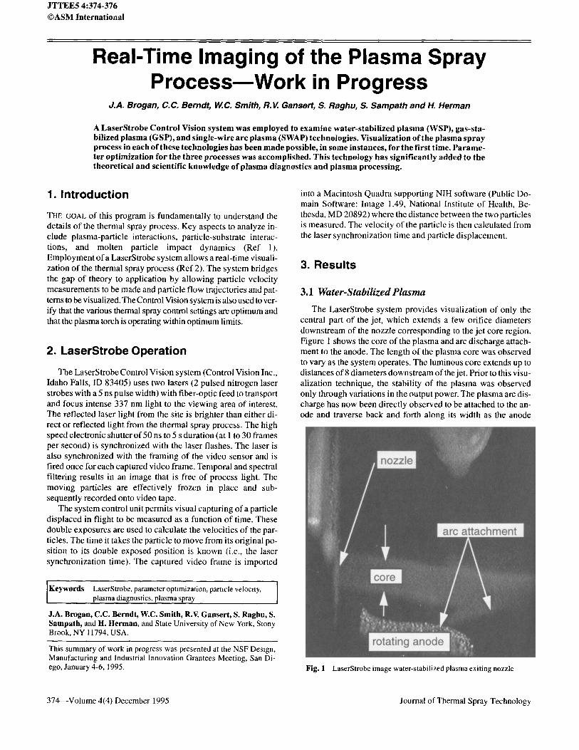
The LaserStrobe system provides visualization of only the central part of the jet, which extends a few orifice diameters downstream of the nozzle corresponding to the jet core region. Figure 1 shows the core of the plasma and arc discharge attach- ment to the anode. The length of the plasma core was observed to vary as the system operates. The luminous core extends up to distances of 8 diameters downstream of the jet. Prior to this visu- alization technique, the stability of the plasma was observed only through variations in the output power. The plasma arc dis- charge has now been directly observed to be attached to the an- ode and traverse back and forth along its width as the anode
I Keywords LaserStrobe, parameter optimization, particle velomty, plasma diagnostics, plasma spray
J.A. Brogan, C.C. Berndt, W.C. Smith, R.V. Gansert, S. Raghu, S. Sampath, and H. Herman, and State University of New York, Stony Brook, NY 11794, USA.
This summary of work in progress was presented at the NSF Design, Manufacturing and Industrial Innovation Grantees Meeting, San Di- ego, January 4-6, 1995. Fig. I LaserStrobe image water-stabilized plasma exiting nozzle
374---Volume 4(4) December 1995 Journal of Thermal Spray Technology
rotates in front of the nozzle exit. A "pinching" effect of the hot plasma core region is also observed resulting from a sheath of cooler gas, which is neither ionized nor conductive, encircling and constricting the plasma jet (Ref 3). This pinching effect in- creases the temperature of the plasma as well as centerline ve- locities (Ref 4). The outer shear layer as well as the downstream flow field was not observed due to entrainment and mixing of the plasma jet with the colder ambient air.
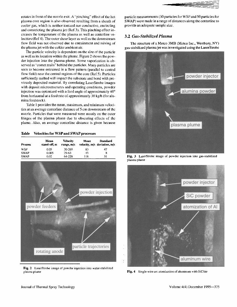
The panicle velocity is dependent on the size of the particle as well as its location within the plume. Figure 2 shows the pow- der injection into the plasma plume. Some vaporization is ob- served as "comet trails" behind the particles. Many panicles are seen to become entrained in a flow pattern (parallel to central flow field) near the central regions of the core (Ref 5). Particles sufficiently melted will impact the substrate and bond with pre- viously deposited material. By correlating LaserStrobe images with deposit microstructures and operating conditions, powder injection was optimized with a feed angle of approximately 40 ~ from horizontal at a feed rate of approximately 38 kg/h (for alu- mina feedstock).
Table 1 provides the mean, maximum, and minimum veloci- ties at an average centerline distance of 5 cm downstream of the nozzle. Particles that were measured were mostly on the outer fringes of the plasma plume due to obscuring effects of the plume. Also, an average centerline distance is given because
Table Velocities for W S P and S W A P processes
Mean Velocity Mean Standard Process stand-off, m range, m/s velocity, m/s deviation, m/s
WSP 0.05 30-269 83 47 SWAP 0.005 29-63 43 8 SWAP 0.02 64-228 118 31
particle measurements (30 panicles for WSP and 50 particles for SWAP) were made in a range of distances along the centerline to provide an adequate sample size.
3.2 Gas.Stabilized Plasma
The structure of a Metco 3MB (Metco Inc., Westbury, NY) gas-stabilized plasma jet was investigated using the LaserStrobe
Fig. 3 LaserStrobe image of powder injection into gas-stabilized plasma plume
Fig. 2 LaserStrobe image of powder injection into water-stabilized plasma plume Fig. 4 Single-wire arc atomizalion of aluminum with SiC/air
Journal of Thermal Spray Technology Volume 4(4) December 1995---375
system, It was observed that pinching of the luminous core oc- curred within 2 to 3 diameters downstream of the jet exit. See Fig. 3. This occurrence is most likely due to entrainment of cold ambient air into the core of the jet (Ref 4). Examination of the particle streaks indicates that the particle paths extend across the luminous core region of the jet. This suggests that there is a large variation in the thermal environment for the externally intro- duced particles into the jet.
3 .3 S i n g l e - W i r e A r c P l a s m a
The LaserStrobe system examined the SWAP gun and al- lowed direct visualization of the degree of atomization. See Fig. 4. If the wire feed rate is too high, the wire will be pushed through the core of the plasma before it is fully melted. In this case, the unmelted wire can be visualized along with a larger particle size distribution for the atomized metal. The larger par- ticles directly affect the deposit quality by producing a rougher coating. The wire feed rate was monitored using the Control Vi- sion system to ensure that complete atomization of the wire oc- curred; therefore, consistently smaller particle sizes resulted.
The control settings were chosen to remove the plasma plume from the SWAP gun in the recorded images. This allowed discrimination of the double exposed particles and, hence, parti- cle velocity because the laser synchronization time and particle displacement can be measured. Table 1 summarizes these meas- urements for the atomized aluminum wire with respect to dis- tance from the wire. An advantage of using Control Vision is that specific particles of interest are selectively chosen for measure- ment, unlike laser doppler velocimetry (LDVM), which meas-
ures the whole family of particles whereupon no particles are specifically discriminated (Ref 6). Velocity data as a function of distance away from the centerline of the nozzle along with a vis- ual record of process phenomena are thus made possible.
Acknowledgments This work is supported by the National Science Foundation
under grant number MSS-9311053 as well as by Flame Spray Industries, Inc., Stony Brook, NY and Control Vision, Inc., Idaho Falls, ID.
References 1. H. Herman, Plasma Spray Depositlon Processes, MRS Bull., December
1988, p 60-67 2. J. Agapakis and T. Hoffman, Real-Time Imaging for Thermal Spray
Process Development and Control, J. Therm. Spray Technol., Vol 1 (No. 1 ), 1992, p 19-25
3. P. Chraska and M. Hrabovsky, Thermal Spray: International Ad- vances in Coatings Technology, C C. Berudt, Ed., ASM International, 1992, p 81-85
4. J. Malinka, D. Varacalle, and W. Rlggs, II, Thermal Spray: Interna- tional Advances in Coatings Technology C C. Berndt, Ed., ASM In- ternational, 1992, p 87-92
5. S. Raghu, G. Gotvenier, R.V. Gansert, "Plasma Diagnostics: A Com- parative Study of the Structure of Gas Stabilized and Water Stabilized Plasma Jets Using the Laserstrobe TM and Focusing Schlieren Tech- niques," paper to be submitted to Experiments m Fluids.
6. W. Mayr, Rapid Opnmization of Spraying Parameters by Means of an Automatic Laser Doppler Measuring Equipment, Proc. llth Int. Ther- mal Spraying Conf., Vol 11, 1986, p 221-230
376~Volume 4(4) December 1995 Journal of Thermal Spray Technology