Embed Size (px)
Citation preview
Real-time control system verification for ELT AO systems
Alastair Basden1, Richard Myers1,
Tim Morris1, Ali Bharmal1, Urban Bitenc1, Nigel Dipper1, Andrew Reeves1, Eric Gendron2, Gerard Rousset2,
Zoltan Hubert2, Fabrice Vidal2, Olivier Martin2, Damien Gratadour2, Fanny Chemla2
AO4ELT331/5/13
1 Durham University2 Observatoire de Paris, LESIA
Contents
● ELT-scale Real-time control solution
● Real-time simulation for system verification
● Jitter measurement
● GPU pipeline
● CANARY tests of robustness
● HOW IT ALL FITS TOGETHER
ELT AO Real-time control systems
● Should be fully tested and robust before commissioning
– So that valuable on-sky time not wasted ● (at €100k/night)
● More complicated than existing systems
– How can we be sure of their robustness?
● Algorithm testing
– How can we be sure that real-time implementations are working correctly?
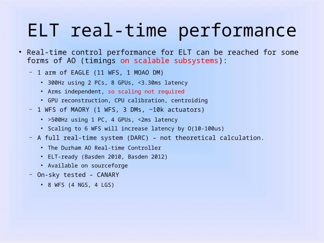
ELT real-time performance● Real-time control performance for ELT can be reached for some forms of AO
(timings on scalable subsystems):– 1 arm of EAGLE (11 WFS, 1 MOAO DM)
● 300Hz using 2 PCs, 8 GPUs, <3.30ms latency● Arms independent, so scaling not required● GPU reconstruction, CPU calibration, centroiding
– 1 WFS of MAORY (1 WFS, 3 DMs, ~10k actuators)● >500Hz using 1 PC, 4 GPUs, <2ms latency● Scaling to 6 WFS will increase latency by O(10-100us)
– A full real-time system (DARC) – not theoretical calculation.● The Durham AO Real-time Controller● ELT-ready (Basden 2010, Basden 2012)● Available on sourceforge
– On-sky tested – CANARY● 8 WFS (4 NGS, 4 LGS)
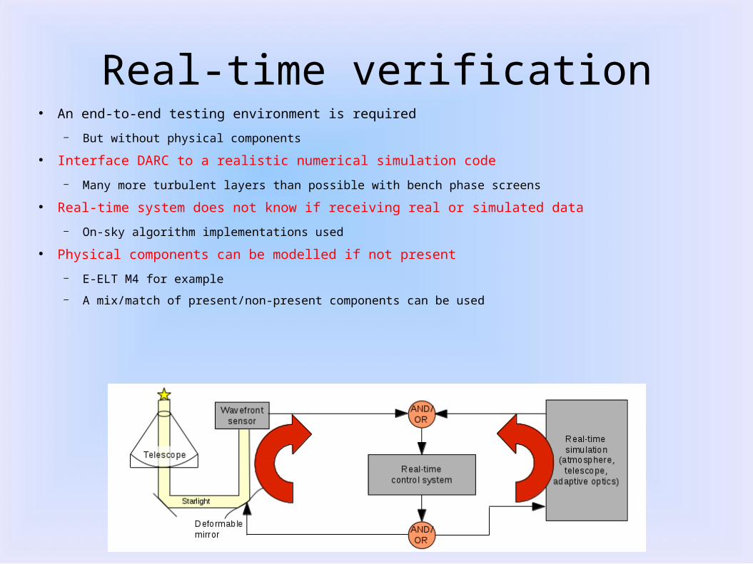
Real-time verification● An end-to-end testing environment is required
– But without physical components
● Interface DARC to a realistic numerical simulation code
– Many more turbulent layers than possible with bench phase screens
● Real-time system does not know if receiving real or simulated data
– On-sky algorithm implementations used
● Physical components can be modelled if not present
– E-ELT M4 for example
– A mix/match of present/non-present components can be used
Real uses for the real-time simulation
● A real example: HWR (a new reconstructor) testing,● HWR is a low-operations reconstructor (see poster, Bharmal et al.)
– Unexpected actuator saturation appeared when used on-sky
– Preliminary test data obtained
– Subsequent testing performed using the real-time simulation● Problems identified and removed
● Avoids changes between C real-time algorithm and the interactive-language implementations used during development● i.e., you use the actual RTC within the simulation
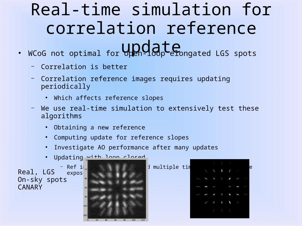
Real-time simulation for correlation reference update
● WCoG not optimal for open-loop elongated LGS spots
– Correlation is better
– Correlation reference images requires updating periodically
● Which affects reference slopes
– We use real-time simulation to extensively test these algorithms
● Obtaining a new reference● Computing update for reference slopes● Investigate AO performance after many updates● Updating with loop closed
– Ref images must be updated multiple times during a science exposure
Real, LGSOn-sky spotsCANARY
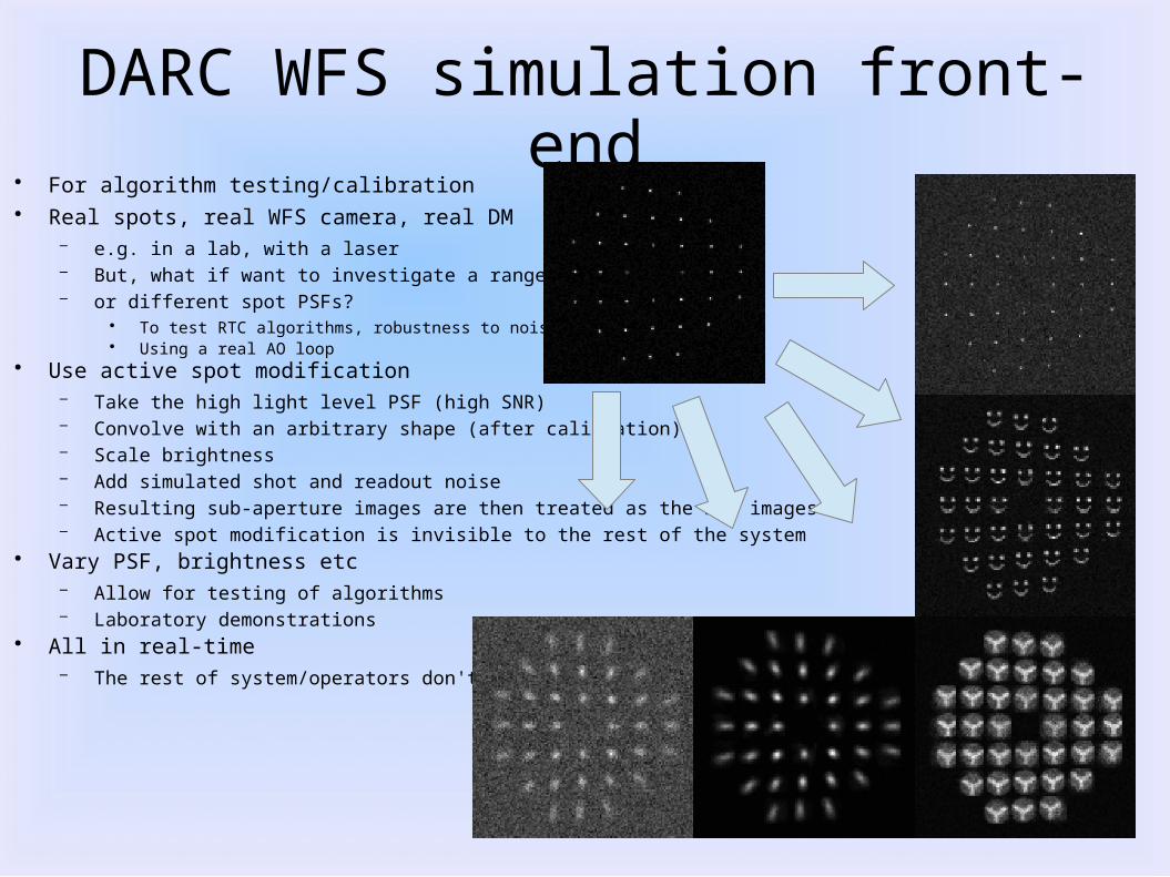
DARC WFS simulation front-end● For algorithm testing/calibration● Real spots, real WFS camera, real DM
– e.g. in a lab, with a laser– But, what if want to investigate a range of fluxes– or different spot PSFs?
● To test RTC algorithms, robustness to noise etc.● Using a real AO loop
● Use active spot modification– Take the high light level PSF (high SNR)– Convolve with an arbitrary shape (after calibration)– Scale brightness– Add simulated shot and readout noise– Resulting sub-aperture images are then treated as the raw images– Active spot modification is invisible to the rest of the system
● Vary PSF, brightness etc– Allow for testing of algorithms– Laboratory demonstrations
● All in real-time– The rest of system/operators don't know
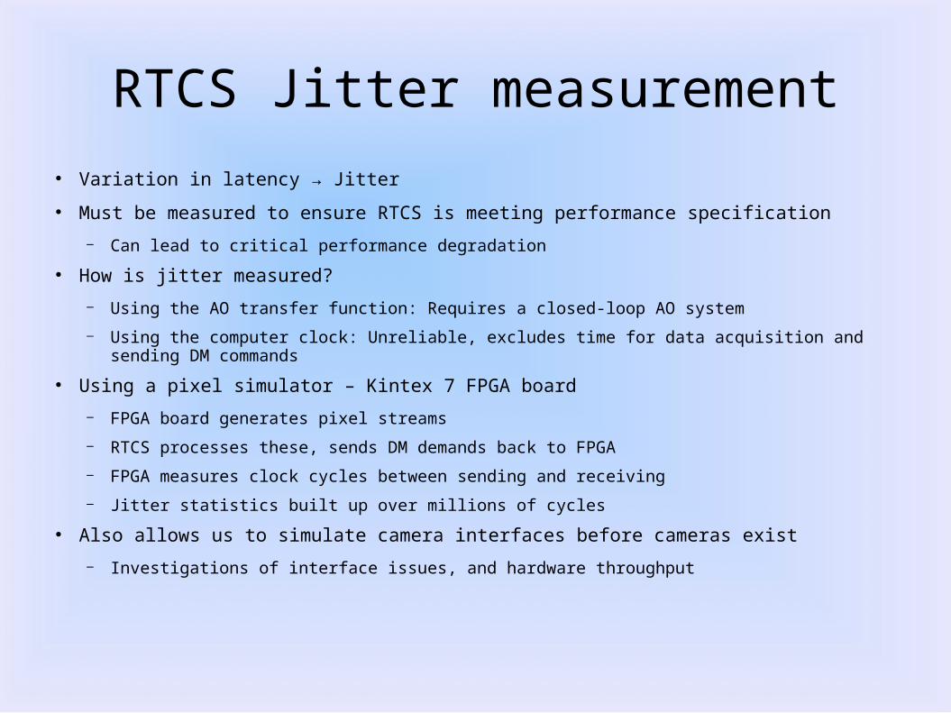
RTCS Jitter measurement
● Variation in latency → Jitter
● Must be measured to ensure RTCS is meeting performance specification
– Can lead to critical performance degradation
● How is jitter measured?
– Using the AO transfer function: Requires a closed-loop AO system
– Using the computer clock: Unreliable, excludes time for data acquisition and sending DM commands
● Using a pixel simulator – Kintex 7 FPGA board
– FPGA board generates pixel streams
– RTCS processes these, sends DM demands back to FPGA
– FPGA measures clock cycles between sending and receiving
– Jitter statistics built up over millions of cycles
● Also allows us to simulate camera interfaces before cameras exist
– Investigations of interface issues, and hardware throughput
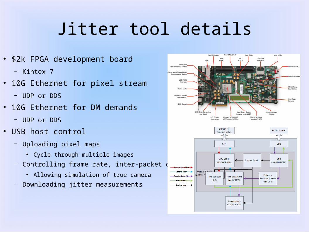
Jitter tool details
● $2k FPGA development board– Kintex 7
● 10G Ethernet for pixel stream– UDP or DDS
● 10G Ethernet for DM demands– UDP or DDS
● USB host control– Uploading pixel maps
● Cycle through multiple images
– Controlling frame rate, inter-packet delay● Allowing simulation of true camera
– Downloading jitter measurements
Real-time control GPU pipeline(Andrew Richards)
● Implementation in GPU of:
– Calibration
– Centroiding (WCoG)
– Reconstruction
● For a study of different GPUs and techniques
– AMD (Radeon HD7970), NVIDIA (GTX580, Tesla C2070)
– CUDA (NVIDIA), OpenCL (NVIDIA and AMD)● OpenCL code identical (except for #include) for AMD and NVIDIA GPUs
● See Poster by N.Dipper et al:● Adaptive Optics Real-time Control in the ELT Era
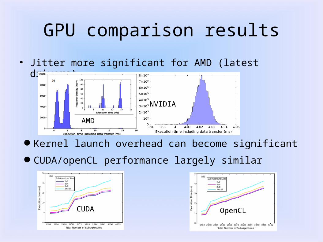
GPU comparison results
● Jitter more significant for AMD (latest drivers)
AMD
NVIDIA
CUDA OpenCL
● Kernel launch overhead can become significant
● CUDA/openCL performance largely similar
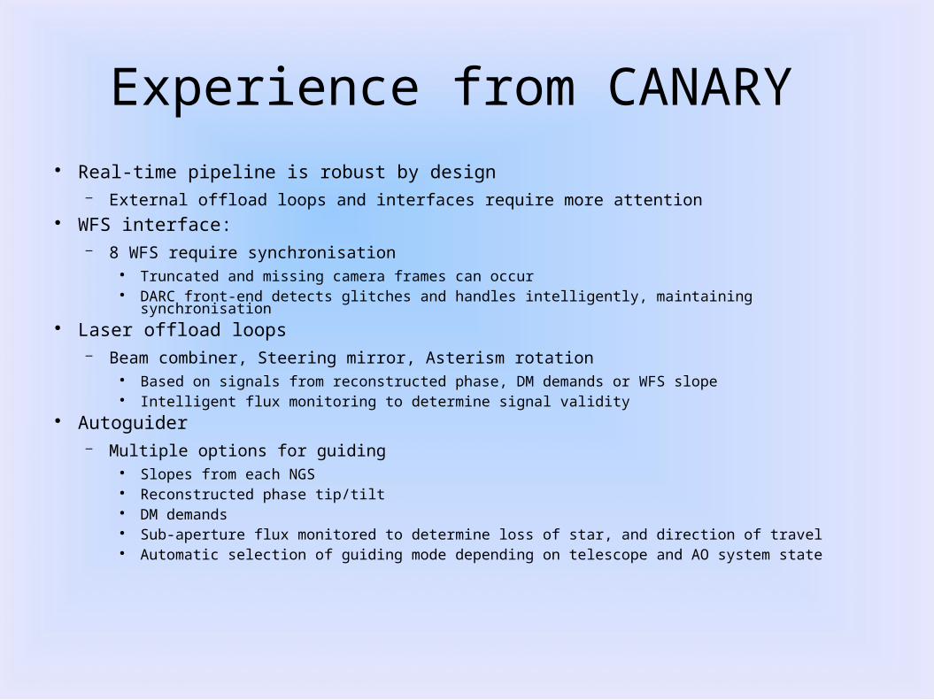
Experience from CANARY ● Real-time pipeline is robust by design
– External offload loops and interfaces require more attention● WFS interface:
– 8 WFS require synchronisation● Truncated and missing camera frames can occur● DARC front-end detects glitches and handles intelligently, maintaining synchronisation
● Laser offload loops– Beam combiner, Steering mirror, Asterism rotation
● Based on signals from reconstructed phase, DM demands or WFS slope● Intelligent flux monitoring to determine signal validity
● Autoguider– Multiple options for guiding
● Slopes from each NGS● Reconstructed phase tip/tilt● DM demands● Sub-aperture flux monitored to determine loss of star, and direction of travel● Automatic selection of guiding mode depending on telescope and AO system state
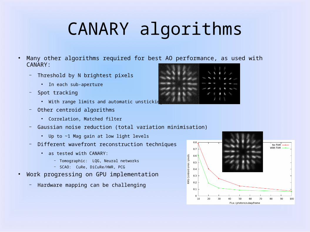
CANARY algorithms
● Many other algorithms required for best AO performance, as used with CANARY:
– Threshold by N brightest pixels
● In each sub-aperture
– Spot tracking
● With range limits and automatic unsticking
– Other centroid algorithms
● Correlation, Matched filter
– Gaussian noise reduction (total variation minimisation)
● Up to ~1 Mag gain at low light levels
– Different wavefront reconstruction techniques
● as tested with CANARY:
– Tomographic: LQG, Neural networks– SCAO: CuRe, DiCuRe/HWR, PCG
● Work progressing on GPU implementation
– Hardware mapping can be challenging
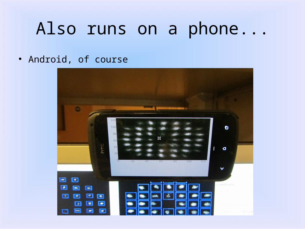
Also runs on a phone...
● Android, of course
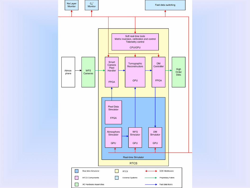
E-ELT Real-time Architecture
• Study to define a common E-ELT real-time system
• ESO, LESIA, Durham, TNO
• See Earlier talk by E Fedrigo
Conclusions
● A roadmap towards a real-time system for some E-ELT scale AO systems is becoming clearer
– More advanced algorithms could still be challenging
– Robustness could be an issue
– Full test harness required● Real-time simulation

![$1RYHO2SWLRQ &KDSWHU $ORN6KDUPD +HPDQJL6DQH … · 1 1 1 1 1 1 1 ¢1 1 1 1 1 ¢ 1 1 1 1 1 1 1w1¼1wv]1 1 1 1 1 1 1 1 1 1 1 1 1 ï1 ð1 1 1 1 1 3](https://img.pdfslide.us/doc/110x75/5f3ff1245bf7aa711f5af641/1ryho2swlrq-kdswhu-orn6kdupd-hpdqjl6dqh-1-1-1-1-1-1-1-1-1-1-1-1-1-1.jpg)
![1 1 1 1 1 1 1 ¢ 1 , ¢ 1 1 1 , 1 1 1 1 ¡ 1 1 1 1 · 1 1 1 1 1 ] ð 1 1 w ï 1 x v w ^ 1 1 x w [ ^ \ w _ [ 1. 1 1 1 1 1 1 1 1 1 1 1 1 1 1 1 1 1 1 1 1 1 1 1 1 1 1 1 ð 1 ] û w ü](https://img.pdfslide.us/doc/110x75/5f40ff1754b8c6159c151d05/1-1-1-1-1-1-1-1-1-1-1-1-1-1-1-1-1-1-1-1-1-1-1-1-1-1-w-1-x-v.jpg)


![[XLS] · Web view1 1 1 2 3 1 1 2 2 1 1 1 1 1 1 2 1 1 1 1 1 1 2 1 1 1 1 2 2 3 5 1 1 1 1 34 1 1 1 1 1 1 1 1 1 1 240 2 1 1 1 1 1 2 1 3 1 1 2 1 2 5 1 1 1 1 8 1 1 2 1 1 1 1 2 2 1 1 1 1](https://img.pdfslide.us/doc/110x75/5ad1d2817f8b9a05208bfb6d/xls-view1-1-1-2-3-1-1-2-2-1-1-1-1-1-1-2-1-1-1-1-1-1-2-1-1-1-1-2-2-3-5-1-1-1-1.jpg)


![1 1 1 1 1 1 1 ¢ 1 1 1 - pdfs.semanticscholar.org€¦ · 1 1 1 [ v . ] v 1 1 ¢ 1 1 1 1 ý y þ ï 1 1 1 ð 1 1 1 1 1 x](https://img.pdfslide.us/doc/110x75/5f7bc722cb31ab243d422a20/1-1-1-1-1-1-1-1-1-1-pdfs-1-1-1-v-v-1-1-1-1-1-1-y-1-1-1-.jpg)